1
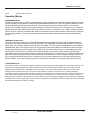
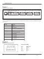
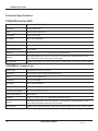
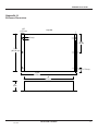
INDUSTRIAL DATA COMMUNICATIONS USER GUIDE CCS9000 Comprehensive Communication System It is essential that all instructions contained in the User Guide are followed precisely to ensure proper operation of equipment. Product User Guide FCC Notification This device complies with part 15 of the FCC rules. Operation is subject to the following conditions: 1) 2) This device may not cause harmful interference and This device must accept any interference received, including interference that may cause undesired operation. The device must be operated as supplied by Data-Linc Group. Any changes or modifications made to the device without the express written approval of Data-Linc Group may void the user’s authority to operate the device. Caution: This device has a maximum transmitted output power of 200 mW. It is required that the transmit antenna be kept at least 23 cm away from nearby persons to satisfy FCC RF exposure requirements. Note: This equipment has been tested and found to comply with the limits for a Class A digital device, pursuant to part 15 of the FCC Rules. These limits are designed to provide reasonable protection against harmful interference in a industrial installation. This equipment generates, uses and can radiate radio frequency energy and, if not installed and used in accordance with the instructions, may cause harmful interference to radio communications. However, there is no guarantee that interference will not occur in a particular installation. If this equipment does cause harmful interference to radio or television reception, which can be determined by turning the equipment off and on, the user is encouraged to try to correct the interference by one or more of the following measures: Reorient or relocate the receiving antenna. Increase the separation between the equipment and receiver. Connect the equipment into an outlet on a circuit different from that to which the receiver is connected. Consult the dealer or an experienced radio/TV technician for help. Note: Whenever any Data-Linc Group PLR series modem is placed inside an enclosure a label must be placed on the outside of that enclosure which includes the modem’s FCC ID. The following antennas are approved for use with Data-Linc Group’s 900MHz series modems. NOTE: Per FCC Rules, the maximum power allowed at the antenna is 4 Watts E.I.R.P. 900MHz Directional Antenna Gain Manufacturer 8.2 dBi Larsen 12.2 dBi Larsen Manufacture Model Number YA6-900W YA0006 Data-Linc Model Number A-YB A-Y10B 900MHz Omni-Directional Antenna Gain Manufacturer 5.2 dBi Maxrad 7.2 dBi Maxrad 0 dBi Ying Hao 0 dBi Centurion Manufacture Model Number MAX-9053 BMEFC8985HD YH920801/AD-725-A-1 EXC-902-BN Data-Linc Model Number A-OB A-O5B A-06/ADJ A-06BH-3S / 10S (**) (**) This part number refers to an antenna kit(s). The 0 dBi refers to the antenna portion of the kit. Note: The antenna used for this device must be professionally installed on a fixed-mounted permanent outdoor structure for satisfying RF exposure requirements, including antenna co-location requirements of 1.1307(b)(3). DATA-LINC GROUP PN 161-09996-003A CCS9000 User Guide Table of Contents Page Description ○ ○ Connections ○ ○ ○ ○ ○ Indicator Lights Operation Quick Test ○ ○ ○ ○ ○ ○ ○ ○ Technical Specifications ○ ○ ○ ○ ○ ○ ○ ○ ○ ○ ○ ○ ○ ○ ○ ○ ○ ○ ○ ○ ○ ○ ○ ○ ○ ○ ○ ○ ○ ○ ○ ○ ○ ○ ○ ○ ○ ○ ○ ○ ○ Appendix A Enclosure Dimensions ○ ○ ○ ○ ○ ○ ○ ○ ○ ○ ○ ○ ○ ○ ○ ○ ○ ○ ○ ○ ○ ○ ○ ○ ○ ○ ○ ○ ○ ○ ○ ○ ○ ○ ○ ○ ○ ○ ○ ○ ○ ○ ○ ○ ○ ○ ○ ○ ○ ○ ○ ○ ○ ○ ○ ○ ○ ○ ○ ○ ○ ○ ○ ○ ○ ○ ○ ○ ○ ○ ○ ○ ○ ○ ○ ○ ○ ○ ○ ○ ○ ○ ○ ○ ○ ○ ○ ○ ○ ○ ○ ○ ○ ○ ○ ○ ○ ○ ○ ○ ○ ○ ○ ○ ○ ○ ○ ○ ○ ○ ○ ○ ○ ○ ○ ○ ○ ○ ○ ○ ○ ○ ○ ○ ○ ○ ○ ○ ○ ○ ○ ○ ○ ○ ○ ○ ○ ○ ○ ○ ○ ○ ○ ○ ○ ○ ○ ○ ○ ○ ○ ○ ○ ○ ○ ○ ○ ○ ○ ○ ○ ○ ○ ○ ○ ○ ○ ○ ○ ○ ○ ○ ○ ○ ○ ○ ○ ○ ○ ○ ○ ○ ○ ○ ○ ○ ○ ○ ○ ○ ○ ○ ○ ○ ○ ○ ○ ○ ○ ○ ○ ○ ○ ○ ○ ○ ○ ○ ○ ○ ○ ○ ○ ○ ○ ○ ○ ○ ○ ○ ○ ○ ○ ○ ○ ○ ○ ○ ○ ○ ○ ○ ○ ○ ○ ○ ○ ○ ○ ○ ○ Appendix C Option AE485 Connections ○ ○ ○ Appendix B Option AE422 Connections PN 161-09996-003A rev 9/03 ○ ○ ○ ○ ○ ○ ○ ○ ○ ○ ○ ○ ○ ○ ○ ○ ○ ○ ○ ○ ○ ○ ○ ○ Technical Support Product Warranty Return Material Authorization Contact Information ○ ○ ○ ○ ○ ○ ○ ○ ○ ○ ○ ○ ○ ○ ○ ○ ○ ○ ○ ○ ○ ○ ○ ○ ○ ○ ○ ○ ○ ○ ○ ○ ○ ○ ○ ○ ○ ○ ○ ○ ○ ○ ○ ○ ○ ○ ○ ○ ○ ○ ○ ○ ○ ○ ○ ○ ○ ○ ○ ○ ○ ○ ○ ○ ○ ○ ○ ○ ○ ○ ○ ○ ○ ○ ○ ○ ○ ○ ○ ○ ○ ○ ○ ○ ○ ○ ○ ○ ○ ○ ○ ○ ○ ○ ○ ○ ○ ○ ○ ○ ○ ○ ○ ○ ○ ○ ○ ○ ○ ○ ○ ○ ○ ○ ○ ○ ○ ○ ○ ○ ○ ○ ○ ○ ○ ○ ○ ○ ○ ○ ○ ○ ○ ○ ○ ○ ○ ○ ○ ○ ○ ○ ○ ○ ○ ○ ○ ○ ○ ○ ○ ○ ○ ○ ○ ○ ○ ○ ○ ○ ○ ○ ○ ○ ○ ○ ○ ○ ○ ○ ○ ○ ○ ○ ○ ○ ○ ○ ○ ○ ○ ○ ○ ○ ○ ○ ○ ○ ○ ○ ○ ○ ○ ○ ○ ○ ○ ○ ○ ○ ○ ○ ○ ○ ○ ○ ○ ○ ○ ○ ○ ○ ○ ○ ○ ○ ○ ○ ○ ○ ○ ○ ○ ○ ○ ○ ○ ○ ○ ○ ○ ○ ○ ○ ○ ○ ○ ○ ○ ○ ○ ○ ○ ○ ○ ○ ○ ○ ○ ○ ○ ○ ○ ○ ○ ○ ○ ○ ○ ○ ○ ○ ○ ○ ○ ○ ○ ○ ○ ○ ○ ○ ○ ○ ○ ○ ○ ○ ○ ○ ○ ○ ○ ○ DATA-LINC GROUP 3 3 3 4 4 5 6 6 6 6 7 8 9 1 CCS9000 User Guide 2 DATA-LINC GROUP PN 161-09996-003A rev 9/03 CCS9000 User Guide Introduction The Data-Linc Group CCS9000 is a micro controller based line of industrial multi-port, multi-path remote modems. It is available in the following specific models differing in designated by the part number suffix: Leased or Private Line Tone [CCS9000/LL] Dial-Up ASCII [CCS9000/DU] Wireless Radio [CCS9000/RAD] The CCS9000 systems permit monitoring, programming and troubleshooting of remote data tracking and controller devices from one or more central locations. Each of the above models has a unique factory firmware address clearly labeled on the outside of its case. This address allows access to each remote in a system using the Connect software package purchased with the system. The CCS9000 can be configured for point to point or multi-point applications. Gateways built into each model allow the user to interface two or more systems providing hassle free integration of unlike communication paths. The CCS9000 is designed to be connected to equipment with an RS232C port. It is also expected to be connected like a PC computer for program setup or data collection purposes. For this reason, the ports of the CCS9000 are configured as DTE, rather than DCE as would be normal for a modem. This allows for a straight through cable for most applications. These ports are not configured to support hardware handshake lines. General Information The CCS9000 Comprehensive Communication System is designed to automatically locate and connect to remote intelligent devices from one or more master locations using the CONNECT software package. The communication path can be any combination of private wire, telco circuits, fiber optic or radio links. This is accomplished through the 6 pin mini-din connector gateway port used to access an auxiliary master. The remote modems have four DB9 connectors that are individually selectable serial data ports. Each port can have a unique baud rate setting from 1200 to 19.2 Kbaud, up to 115.2 Kbaud on the radio version. Each port can also be associated with an application that interfaces with the intelligent device connected to it. When a connection has been completed successfully the application will launch automatically. The ports are configured for RS232 asynchronous DTE operation. LED indicators on the front panel of each remote provide visual operational and diagnostic information for power, data in and data out, tone detection (CCS9000/ LL model), carrier detect and selection of PN 161-09996-003A rev 9/03 DATA-LINC GROUP 3 CCS9000 User Guide the four individual ports. CCS9000 Master Units The CCS9000 Master units consist of Data-Linc Group’s DLM4100 series for dial-up and leased line, and the SRM6000 for radio. Each is factory configured to operate with the CCS9000 system. CCS9000 Remote Units Each remote CCS9000 has a unique firmware imbedded five digit address and configuration that is factory programmed into. The address can be found on the outside of the enclosure and on the controller board inside of each unit. The configuration is dependant upon the model of modem ordered and is not user accessible. A diagram of this pin out of the DB9 connector is provided in the appendices. Port baud rate settings are selectable with the CONNECT software application. A feature unique to the DATA-LINC GROUP CCS9000 remote is its gateway port connector. The 6 pin mini-din connector on each remote is designed to integrate a secondary CCS9000 master allowing the seamless integration of different communication media. The integration is accomplished entirely through the use of firmware and the CONNECT software, there is no user hardware configuration needed. All units shipped from the factory with the gateway capability. Connecting the cable supplied with each auxiliary master to the gateway port is all that is required. The barrel connector on each remote is for 9 volt ac power. There are LED indicators on each remote which provide diagnostics for the following: Red Red Yellow Green Amber Amber Green Green Green 4 Speaker (Dial Up and Leased Line Only) Power Indication Data Out of active port Data In the active port Tone Detection (Leased Line Only) Carrier Detection Indicates Port 1 is active Indicates Port 2 is active Indicates Port 3 is active DATA-LINC GROUP PN 161-09996-003A rev 9/03 CCS9000 User Guide Green Indicates Port 4 is active Operating Modes CCS9000/DU Dial-Up The dial-up remote version is a Trellis Coded Modulation Carrier designed to be used with standard analog telco circuits. The unit’s unique five digit address is transmitted in standard ASCII code format. The yellow carrier indicator will come on solid if the address received matches the unit’s. The port that was chosen to connect to will then come on solid indicating a successful connection. When data is flowing out of the port to the device it is connected to the ‘O’ Data Out indicator will flash. When data is flowing into the port from the device it is connected to the ‘I’ Data In indicator will flash. There is an RJ11 connector provided for the carrier line connection, the two center contacts are the only ones used and are not polarity sensitive. They are the red and green wires with terminal connections on the cable provided with the remote. CCS9000/LL Leased Line The leased line remote version is a Trellis Coded Modulation Carrier designed to be used with conditioned leased or private lines. Two twisted conductors are all that is needed. Line conditioning is available through Data-Linc Group for private lines. For local telco leased lines this device is not needed. The unit’s unique five digit address is transmitted in standard DTMF tones. The recognition of tones can be observed through the amber tone indicator on the front panel it will light momentarily during the receiving of any DTMF signal. If the tones match the unit’s unique address the yellow carrier indicator will then come on solid. The port that was chosen to connect to will then come on solid indicating a successful connection. When data is flowing out of the port to the device it is connected to the ‘O’ Data Out indicator will flash. When data is flowing into the port from the device it is connected to the ‘I’ Data In indicator will flash. There is an RJ11 connector provided for the carrier line connection, the two center contacts are the only ones used and are not polarity sensitive. They are the red and green wires with terminal connections on the cable provided with the remote. CCS9000/RAD Radio The wireless model is a 902 to 928 megahertz spread spectrum frequency hopping radio unit. Algorithms utilize up 110 frequencies in hopping patterns that ensure excellent noise immunity and high reliability. The unit’s unique five digit address is transmitted via RF in standard ASCII code format. The yellow carrier indicator will come on solid if the address received matches the units. The port that was chosen to connect to will then come on solid indicating a successful connection. When data is flowing out of the port to the device it is connected to the ‘O’ Data Out indicator will flash. When data is flowing into the port from the device it is connected to the ‘I’ Data In indicator will flash. There is a SMA connector provided for the antenna connection. Data-Linc Group strongly suggests that a professional complete the installation of the antenna and cable. Refer to the documentation included with the antenna/cable and bracket assembly purchased separately from Data-Linc Group. PN 161-09996-003A rev 9/03 DATA-LINC GROUP 5 CCS9000 User Guide Diagram 1 Led and Connector Locations S P 9AV Aux. Phone Line O I T Port 5 C 1 2 Port 1 3 Port 2 Port 3 4 Port 4 There are ten LED indicators on the front panel of the CCS9000/DU and CCS9000/LL, nine on the CCS9000/RAD. From left to right they are: Marking Function S S p e a ke r P Power Applied O Data flowing out of RS-232 port I Data flowing into RS-232 port T Tone Detection by Remote C Carrier Detect 1 Port 1 selected 2 Port 2 selected 3 Port 3 selected 4 Port 4 selected Diagram 2 RS232 Pin Functions and Pin Out Port Connector DB9M 8 9 5 6 4 7 3 6 2 1 Pin 1 Pin 2 Pin 3 Pin 4 Pin 5 Pin 6-9 DATA-LINC GROUP Carrier Detect Data In Data Out N/U Ground N/U PN 161-09996-003A rev 9/03 CCS9000 User Guide Installation When the system was ordered, information that defined the architecture of the system was requested. This information was used to configure the various devises and the CONNECT software. All that the user need do is install the devises as described at that time. Make the appropriate connections between the CCS9000’s and the devises to be communicated with. In the case of dial-up and leased line versions, the necessary connections need to be made with the carrier lines. In the case of private lines a line conditioning circuit will be required, Data-Linc Group can supply this where needed. For radio modem systems, the antennas will need to mounted in the proper locations and cabled to the modems. It is recommended that someone skilled in radio modem installations be consulted for this task. Remembering that the antennas need to have a good line of sight between them for the radio modems to work properly. In the rare event that any modem within a given CCS9000 needs to be reconfigured please contact Data-Linc Group technical support for the procedure. Operation Once all of the required connections are made the system maybe powered up. Please refer to the software operations manual for operational instructions. General Operating Notes The CCS9000 and the CONNECT software have been carefully designed to operate in concert with each other. The system is completely expandable and may be easily updated as the connected equipment either changes or is expanded. One of the main design goals was to have the communications path be transparent to the equipment and its’ control software. One way to speed up the changing of ports within a given remote system is to have all the port speeds setup to the same baud rate. The obvious trade off here is that the equipment that can communicate at a faster rate will be slowed down. However, the time it takes to reconnect to a different port will be much faster. The user has full control over this. PN 161-09996-003A rev 9/03 DATA-LINC GROUP 7 CCS9000 User Guide Technical Specifications CS9000/DU Dial-Up ASCII Data Format Asynchronous RS-232 10 bit word Operation Dial-Up Phone Lines Mode Point-to-Point or Multi-Point Data Rates 1200 to 19.2 Kbaud Modulation Trellis Coded Modulation Distance Unlimited on dial-up lines Operating Temperature -400 to +1850 (-400 to +850 C) Power Requirements 9v AC 400mA Enclosure 2.0" H x 7.75" W x 11.25" L; 1 gauge steel; polyurethane paint Interface Four DB9M for RS-232C; RJ11 for carrier line; 6 pin mini-din for auxiliary master; 2.5mm x 5.5mm barrel jack (center positive) for 9v AC power LED Indicators Speaker, Power, Data Out, Data In, Tone Detect, Carrier Detect, Port 1, Port 2, Port 3, Port 4. CCS9000/LL Leased Line Data Format Asynchronous RS-232 10 bit word Operation Telco Leased Lines or Private, Conditioned Lines Mode Point-to-Point or Multi-Point Data Rates 1200 to 19.2 Kbaud Modulation Trellis Coded Modulation Distance Unlimited on conditioned private, or Telco Leased Lines Operating Temperature -400 to +1850 (-400 to +850 C) Power Requirements 9v AC 400mA Enclosure 2.0" H x 7.75" W x 11.25" L; 1 gauge steel; polyurethane paint Interface Four DB9M for RS-232C; RJ11 for carrier line; 6 pin mini-din for auxiliary master; 2.5mm x 5.5mm barrel jack (center positive) for 9v AC power LED Indicators Speaker, Power, Data Out, Data In, Tone Detect, Carrier Detect, Port 1, Port 2, Port 3, Port 4. 8 DATA-LINC GROUP PN 161-09996-003A rev 9/03 CCS9000 User Guide CCS9000/ RAD Wireless Radio Data Format Asynchronous RS-232 10 bit word Operation License free 902-928 MHz Spread Spectrum Mode Point-to-Point or Multi-Point Data Rates 1200 to 115.2Kbaud Modulation Frequency hopping, 32 bit CRC error detection Distance Guaranteed 20 miles lin of sight, 60 miles with repeaters Operating Temperature -400 to +1670 (-400 to +750 C) Power Requirements 9v AC 700mA Enclosure 2.0" H x 7.75" W x 11.25" L; 1 gauge steel; polyurethane paint Interface Four DB9M for RS-232C; SMA for antenna 6 pin mini-din for auxiliary master; 2.5mm x 5.5mm barrel jack (center positive) for 9v AC power LED Indicators Speaker, Power, Data Out, Data In, Tone Detect, Carrier Detect, Port 1, Port 2, Port 3, Port 4. PN 161-09996-003A rev 9/03 DATA-LINC GROUP 9 CCS9000 User Guide Technical Support Data-Linc Group maintains a fully trained staff of service personnel who are capable of providing complete product assistance. They can provide you with technical, application and troubleshooting, spare parts and warranty assistance. Our technical staff is based in Bellevue, Washington USA and may be reached at (425) 882-2206 or e-mail [email protected] Product Warranty Data-Linc Group warrants equipment of its own manufacture to be free from defects in material and workmanship for one year from date of shipment to original user. Data-Linc Group will replace or repair, at our option, any part found to be defective. Buyer must return any part claimed defective to Data-Linc Group, transportation prepaid. Return Material Authorization If a part needs to be sent to the factory for repair, contact Data-Linc Group’s corporate office and request a Return Material Authorization (RMA) number. The RMA number identifies the part and the owner and must be included with the part when shipped to the factory. Contact Information Corporate Office Data-Linc Group 3535 Factoria Blvd. SE Suite 100 Bellevue, Washington 98006 USA Telephone: (425) 882-2206 Fax: (425) 867-0865 E-mail: [email protected] Web site: www.data-linc.com 10 DATA-LINC GROUP PN 161-09996-003A rev 9/03 CCS9000 User Guide Appendix A Enclosure Dimensions .69” (1.75 cm) top view .25” (.63 cm) 3.94” (10 cm) 7.88” (20. 02 cm) .688” (1.75 cm) 11.25“ 28.58 cm 10” 25.4 cm 2“ 5 cm side view PN 161-09996-003A rev 9/03 DATA-LINC GROUP 11