1
Broadcast Devices, Inc.
Technical Reference Manual
AES-302 Digital Audio System
Two Input Digital Audio Switcher
Four Output Digital Distribution System
96 KHz – 24 Bit Digital to Analog Converter
Broadcast Devices, Inc.
5 Crestview Avenue
Cortlandt Manor, NY 10567
Tel. (914) 737-5032
Fax. (914) 736-6916
World Wide Web: www.Broadcast-Devices.com
Rev C. 02/07
2
Table of Contents
I. Introduction
3
II. Unpacking
3
III. Installation and Connections
3
IV. Features and Operation
3
V. Initial Operations Setup
Theory of Operation – Digital Switcher
Error Switching Table 1.
Silence Sensor Setup Table 2.
Remote Control Pin out Table 3.
VI. Specifications
5
5
5
6
7
VII. Warranty
8
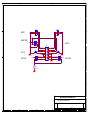
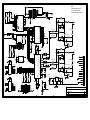
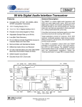
VIII. Schematic Diagrams
9-12
4
3
I. Introduction
The AES-302 Digital Audio System comprises of a two input AES compatible switcher, four output
digital audio DA and digital to analog converter. The unit also has status and diagnostic error indicators for
troubleshooting. The AES-302 is intended for use at unattended transmitter sites or for virtually any digital
switching, distribution and/or D/A conversion application. The unit has the capability to automatically
switch inputs upon detection of loss of clock, digital error flags and/or silence sense. In addition to these
features, the unit can function as an interface standards converter. As shipped from the factory the unit is
supplied with XLR balanced connectors. The unit can be configured with any combination of input/output
connectors if desired. Default factory supplied connections are XLR. Optical and S.P.D.I.F – RCA
connections are available as options.
II. Unpacking and Inspection
Carefully inspect the unit after unpacking and make certain that no damage has occurred during shipping.
If damage is noted, contact the shipper immediately and file a claim for damages. Each unit is carefully
packed and carries full insurance against damage. Inspect the packing list and make sure that the contents
of the package match those described on the packing list.
III. Installation and Connections
Select a space in suitable E.I.A. standard rack to locate the unit. Determine the local electrical power
supply voltage and select the proper input voltage at the rear of the unit. As supplied from the factory, your
AES-302 is setup for 120 V.A.C. 60 Hz unless noted otherwise. To change the input voltage to 240 volts,
simply slide the plastic cover and remove the p.c. board in the E.M.I. protected power entry module and
flip it so that “240 Volts” is legible from the rear as the board is placed back into the power entry module.
No replacement of the fuse is necessary as the fuse supplied is rated for up to 250 V.A.C. operation. The
unit is rated to run from 120/240 V.A.C. at 50 to 60 Hz operation. Make connections to the unit following
good engineering practice. Supply power to the unit utilizing a three pronged grounded outlet. Do no lift
the electrical ground to the unit at the power receptacle as this will result in a safety hazard. In the event of
ground loops, lift the ground at the offending connection only. Make certain that the unit is afforded proper
ventilation in the area of the top cover vent.
A. Digital Interface
Unless ordered as an option Inputs to the switcher are balanced XLR connectors conforming to the AES
standard. The unit may be ordered with SPDIF or optical interface. Each XLR connection is terminated at
110 ohms as per the standard. SPDIF inputs are terminated at 75 0hms. The balanced digital outputs are
also XLR connections, which provide 110-ohm transformer coupled source impedance as per the standard.
Again as an option outputs can be configured for SPDIF or optical interface.
B. Analog Interface
There is provided on the rear of the unit a left/right balanced analog output. This output is suitable for
driving 600-ohm balanced lines and is short circuit protected. A headphone jack and volume control
buttons are provided on the front panel of the unit for confidence monitoring of the incoming feed.
IV. Features and Operation
The AES-302 Digital Audio System is designed to select one of two AES3 compatible feeds and route it to
up to four balanced, optical or unbalanced digital loads. It also contains a high quality digital to analog
4
converter providing a balanced left and right output. The unit features a front panel headphone output and
volume control for easy confidence monitoring. The AES-302 can be used as a totally automatic switcher
sensing loss of clock or any error displayed on the front panel to command the switcher to select the
alternate feed. In addition to digital error switching, the unit features a silence sense circuit for switching
upon audio failure conditions. All automatic switching functions are user defined and can be initialized
with a simple DIP switch setting upon installation of the unit. Command of the switcher can also be
performed manually at the front panel or remotely.
Remote control of the unit is accessed through the rear panel 9 pin D connector. Simple momentary ground
closure to the appropriate pin selects channels and error reset. Status of channel selected and error flag is
also available at this connector. Refer to the pin out table 3 on page 6 for connection information. The
interface is compatible with open collector command. The AES-302 supplies +15 V.D.C. for powering
open collector actuators.
Two additional features that have been added to later production AES-302 units includes power fail feed
through of the selected input to AES output #1 and a delay circuit has been added to the automatic
switching function. With no power connected to the unit, the AES-302 will pass the last selected input
signal to the #1 AES output through K3 NC contacts. Upon power application K3 energizes and AES #1
output receives its signal from U2 RS-485 driver. The additional delay was added to prevent the unit from
switching on momentary glitches that can occur in STL equipment. An added 3 seconds to the switching
time prevents the unit from switching under transient conditions.
V. Initial Operating Set up
Attach input and output connections to the unit using the appropriate connector. The unit can be supplied
with XLR, S.P.D.I.F., or optical connectors at any of the inputs or outputs. If the connector scheme
supplied is not the one desired, consult the factory for a field or factory connector modification.
Plug the remote control plug in and tighten the connector screws in place.
You may select any or all of the error flag and/or silence sense switching, which will command the
switcher to switch to the alternate path. The “no lock” position S6-2 is always selected for automatic
operation. Other error flags and the silence sense error are selected by placing the designated DIP switches
to the on position. Refer to the theory of operation section table 1 on page 5 for possible settings. Once
this is done, the unit is ready to be powered up for operation. The default setting is to command the
switcher upon loss of clock. When the silence sense error is selected for switching, there are several
configurations possible. It is possible to monitor both left and right channels and switch upon complete
audio loss or to have the silence sensor switch upon loss of left or right channel individually. This feature
was added so that non correlated audio feeds can cause the silence sensor to switch where one feed may
take precedence over another. Selection of L+R, Left, or Right only audio is done by placing the proper
jumpers on the motherboard. Refer to the theory of operation section table 2 on page 5 for the various
settings.
Once power is applied and a valid AES bit stream is applied to the selected input, the unit will default to
“Manual” mode of operation. The LED indicator over the “Manual” button should be illuminated. In
addition, the channel selected LED indicator will be lit. There should also be an indication of sample
frequency. Press the error-reset button to clear any errors that might be indicated. If the digital audio stream
feeding the active channel of the unit is valid and no errors occur the unit is ready for to be placed in the
automatic mode if desired. If any of these errors occur after depressing the error-reset button, then the feed
to the unit is defective and should be investigated. If all is in order, the unit is now ready for operation. All
that is left to do is to select the desired feed and then if desired, place the unit in automatic switch mode by
depressing the “Auto” button. The LED indicator will light indicating automatic control of the switcher.
The unit will remain in this mode until an error is detected, loss of lock occurs, silence is detected or the
alternate feed is manually selected. If any of these events occur, the unit will switch to the alternate path
5
and remain there until the error reset is performed from the front panel or remotely. Please note that the
Auto light will remain lit after an automatic switch but that the unit will perform no further
switching until the error reset is performed. This feature insures that the unit will switch only once after
error or loss of clock is detected and prevents the unit from “hunting” back and forth. In addition, errors
and lock loss indications are held in a buffer until cleared by the error-reset button. This is provided for
troubleshooting purposes. If power is lost to the unit, the AES-302 will reset to “Manual” operation upon
reapplication of power and remain in the channel last selected before power loss.
Theory of Operation – Automatic Switcher Circuit.
The AES-302 is designed to operate in automatic and manual switching modes. Upon application of power
the unit defaults to the manual mode. In this mode switching between channels can only be accomplished
by pressing the desired channel button or commanding the desired remote control pin. With power
application C37 pulls the clock pin 3 of U6A low thus placing the IC in the reset mode whereby pin 1 Q
output is pulled low. This in turn cuts off Q2 preventing automatic switching from occurring. Depressing
the “Auto” front panel button places the unit in automatic operation. The actuation of the “Auto ” button
places a high on pin 6 of U6A which in turn sets Q output high enabling Q2. When an error or silence
sense timeout occurs, a delay of approximately 3 seconds is provided via U16 LM741 which acts as a
comparator. Once the delay of U16 times out the comparator flips pulling the base of Q4 low which
saturates Q3 momentarily. Momentary operation of Q3 is due to C45 being in an initially discharged state.
When Q3 is turned on C45 begins to charge enabling Q3 to pass current. This same current passes through
Q2 whose collector is routed to the proper coil of K1, which is the signal routing relay. K1 fires and
switches to the alternate path. No further switching will occur because the error signal is still present on the
base of Q4. This error signal will remain until the error-reset button is pressed. Once the reset occurs, U16
changes output state back to a positive condition which causes Q4 to be saturated. Once Q4 saturates Q3 is
cutoff and C45 begins to discharge through R32. CR19 prevents unintentional operation of the automatic
switch circuit when errors are reset by momentarily cutting off Q2. C38 aids in preventing unintentional
operation by holding the base of Q2 low until the error has had sufficient time to clear.
The silence sensor accepts audio from the left/right output of the AES-300 module via jumpers J-1 and J-2.
To select both channels place both jumpers in the position closest to the front of the unit. For left channel
only place only J1 in the forward position. For right only place J2 in the forward position. The audio is
then amplified by U15A and is rectified by CR20. The D.C. output of CR20 is then fed to C56 which
stores the D.C. sample until a loss of audio occurs. Once loss of audio is encountered, C56 begins to
discharge through R56 and/or R59. After a time delay of 30 or 60 seconds U15B-7 goes negative and is
clamped by CR22 to 0 volts D.C. This 0 volt indication causes CR21 to conduct pulling the base of Q4 low
which initiates the switching action as described above. If silence sensing is not desired, place S6-6 in the
off position.
Any or all of the errors that appear on the front panel display can be made to actuate a switching operation.
Factory default is all error and silence sensing selected. To change this configuration, remove the top cover
and locate S6 on the motherboard. Refer to table 1 below for switch settings:
Error Switch Actuation Table 1
S6-1
S6-2
S6-3
S6-4
S6-5
S6-6
S6-7
S6-8
Coding
Unlock (must be selected for auto operation)
Parity
CRC
Slipped Sample
Silence Sensor
30 seconds *
60 seconds
* For 30 second delay place both S6-7 and S6-8 in the “On” Position
6
Silence Sensor Setup Table 2
J1/J2 in place
J1 in place J2 removed
J1 Removed J2 in place
L+R – default
Left only causes silence sensing
Right only causes silence sensing
Remote Control Pin out Table 3
Pin 1
Pin 2
Pin 3
Pin 4
Pin 5
Pin 6
Pin 7
Pin 8
Pin 9
+15 VDC @100mA.
No Connection
Select B Input
Select A Input
Error Reset
Status Relay Common
Status – “B” Selected
Status - “A” Selected
Ground
Command input pins 3, 4, 5 require a momentary closure to ground. Status connections are to dry contacts.
Use no more than 24 VDC on these contacts or damage to the relay can occur.
7
VI. Specifications
Digital Inputs:
Two – Any combination of XLR, SPDIF or Optical
Digital Outputs:
Four – Any combination of XLR, SPDIF or Optical
Analog Output:
Balanced L/R XLR + 4 dBm 600 Ohms – Rear Panel
Headphone out 600 Ohm unbalanced - Front Panel
Sample Rate Range:
8 – 96 KHz, Auto Detect and Lock
D/A Converter Resolution:
up to 24 bits
Remote Control:
Momentary ground closure selects channels and
resets auto mode operation
Remote Status:
Channel Select Dry Contact NO/C/NC
Front Panel Controls:
7 - Momentary Push buttons - Switcher Selection,
Error Reset, Auto/Manual Mode Operation Select,
and Volume Up/Down
Front Panel Indicators:
Sample Rate, Lock Loss, Error Flags, Power Supply
Status, Channel Status, Auto/Manual Mode
Power Requirements:
120/240 V.A.C. @ 0.25A; 50 – 60 Hz.
Operating Environment:
0 – 60 Degrees Celsius Non Condensing Atmosphere
Physical:
19”W X 8”D X 1.75”H Mounted via Standard E.I.A.
19” rack one rack unit occupied. Weight: 9 LBS.
8
VII. Warranty
Broadcast Devices, Inc. products are warranted against failure due to faulty materials or workmanship for
a period of one year from the date of shipment to the ultimate user. The warranty covers repair or
replacement of defective parts at the factory, provided the unit has been returned prepaid by the user. All
shipments to the factory shall have affixed to the outside of the container an R. A. number obtained from
the factory. The above warranty is void if the unit has been modified by the user outside of any
recommendations from the factory or if the unit has been abused or operated outside of its electrical or
environmental specifications. If customer conducted field tests suggest that the unit may be faulty, whether
or not the unit is in warranty, a full report of the difficulty should be sent to Broadcast Devices, Inc. factory
at Cortlandt Manor, New York. The office may suggest further tests or authorize return for factory
evaluation.
Units sent to the factory should be well packed in the original packing if possible and shipped to
Broadcast Devices, Inc. 5 Crestview Avenue, Cortlandt Manor, NY 10567. Remember to affix the R.A.
number to the outside of the carton. Any packages received without such R.A. number will be refused.
Note: freight collect shipments will also be refused. When the unit has been received, inspected and tested,
the customer will receive a report of the findings along with a quotation for recommended repairs, which
are found falling outside of the standard warranty. Units returned for in-warranty repairs which are found
not to be defective will be subject to an evaluation and handling charge. In-warranty units will be repaired
at no charge and returned via prepaid freight.
Out-of-warranty units needing repair require a purchase order and will be invoiced for parts, labor, and
shipping charges.
When ordering replacement part, always specify A) Part number or Description, and Quantity; B) Date of
Purchase, Where Purchased; C) Any Special Shipping Instructions. Always specify a street address, as
shipping companies cannot deliver to a postal box.
Broadcast Devices, Inc. is not responsible for any other manufacturer’s warranty on original equipment.
Nor are we responsible for any failure, damage, or loss of property that may occur due to the installation or
operation of our equipment outside of recommended specifications.
Broadcast Devices, Inc. may from time to time make changes to the materials used in the manufacture of
its equipment and reserves the right to do so without further notice.
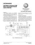
9
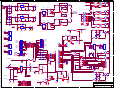
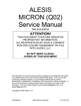
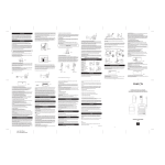
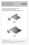
VIII. Schematic Diagrams
5
4
3
2
1
CR1
J1
K3
INPUT-P
6
R1
4
2 T1
1
13
3
4
4
2
1
8
Vo
R11
120 1/2W
CR7
C17
1N4007 .1 50V
CR8
1N4007
C25
CR10
C27
1N4007 .1 50V
C28
3300uF 25V
2
+15V
R16
100 1/2W
+5V
R13
10.0K 1% MF
C23
1
6
4
1
6
2
5
150uF 50V
1
2
3
4
5
6
+5V
TXP4
8
2 T4
1
54R9 1/4W
SILENCE
U15B
1K
6
5
R17
+15V
R53
1K
4
3
4
2
1
54R9 1/4W
R41
1.3K
6
5
Schott-67137640
L1
.47mH
300 1/4W
J7
C29
.0033uF
C30
.0033uF
C31
.0033uF
L2
C32
.0033uF
4
2
L-OUT
1
R56
C54
100K
R18
-15V
R57
SLP SAMP
CM5693
DS4
44KHZ
32KHZ
1
3
5
7
9
11
13
15
SLIPSAMP
CRC
PARITY
CODING
NOLOCK
SEL
E-LED
2
4
6
8
10
12
14
16
PARITY
CODING
UNLOCKED
HDR16DUAL
RANGE
J13
CM5693
DS3
DS5
1.3K 1/4W
R23
CM5693
R25
RSTERR
1N914
1N914
CR15
CR16
1N914
1
2
3
4
5
6
7
8
CR21
1N914
SILENCE
Q1
1N914
100K 1/4W
C35
.1 50V
1N914
47uH
U12
TORX176
1
2
3
4
5
6
L6
+5V
47uH
C49
.1 50V
OUT
DGND
Vcc
AGND
CASE
CASE
J8
RAUDIO
2
15
3
INPUT-N
9
INPUT-P
C50
.01 50V
11
4
R26
13
+15V
1.3K 1/4W
14
-15V
14
1
16
15
5
+15V
CR18
1N914
R30
10K 1/4W
2
11
LEDCH1
9
LEDCH2
12
RYCH1
10
RYCH2
SELCH2
C34
RYCOM
C33
T84S17D434
.1 50V
14
R32
47K 1/4W
CR23
R60
1N914
1K 1/4W
R31
Q4
2N3904
.1 50V
C57
.1 50V
100K 1/4W
4
AUTO DEF
8
11
AUTOENSW
AUTO EN
R34
+15V
2
4
6
8
10
12
14
16
SELCH2
LEDCH2
LEDCH1
VOLDN
C58
4.7uF 25V
AUTODEFSW
AUTODEFLED
68 1/2W
R36
13
1
16
9
R62
SELCH1
SELCH2
1K 1/4W
CR24
1N914
Q5G6A-235P
2N3904
U16
LM741
6
3
-
2
R35
C42
.0033uF
L4
C43
.0033uF
4
2
R-OUT
1
.47mH
{}
-15V
10K 1/4W
C44
4.7uF 25V
Title
Size
C
Date:
3
C41
.0033uF
300 1/4W
R63
470 1/4W
HDR16DUAL
4
J10
C40
.0033uF
A
+
5
1
4
AUTODEFSW
P4
R61
4.75K 1/4W
6
PTC
300 1/4W
+15V
K2
AUTODEFLED
1
3
5
7
9
11
13
15
L3
.47mH
+15V
AUTOENLED
DB9F
FB1
FB
F1
+15V
R33
C45
22uF 25V
P3
5
9
4
8
3
7
2
6
1
SELCH1
.1 50V
C39
INPUT 2
1
RSTERR
Q3
2N3904
C38
22uF 25V
4
R24
110 1/4W
8
SET
B
J9
6
C36
.1 50V
12
C51
.01 50V
RESET
7
DIGOUT
INPUT 1
1
R20
110 1/4W
K1
10
Q2
2N3904
2
68 1/2W
CR12
1N914
8
4
2
+15V
13
100K 1/4W
+15V
5
C47
.01 50V
RXP2
OUT
DGND
Vcc
AGND
CASE
CASE
R19
LAUDIO
7
+15V
R29
VDD
GND
U11
TORX176
1
2
3
4
5
6
HDR3
6
SILSELIN
1
Q
CLK
RESET
D
SET /Q
+15V
AUTOENSW
AUTOENLED
C46
.01 50V
RXP1
+5V
5
150K
R59
R27
1M 1/4W
CR19
U6A
MC14013B
SELCH1
LEDCH1
RSTERR
VOLUP
C56
470uF 16V
L5
4
150K
R38
1K 1/4W
SILSELIN
.1 50V
3
SW DIP-8
R58
+15V
7
3
C55
+15V
2
16
15
14
13
12
11
10
9
2N3906
+15V
3
4
5
6
3
1N914
1
S6
1.3K 1/4W
.1 50V
2
U15A
300 1/4W
P2
R50
1K 1/4W
-15V
R28
10K 1/4W
2
HDR3
CR13
CR14
R22
C37
1
CR20
C48
.1 50V
1N914
+15V
470 1/4W
J14
1
TLO72
1
R54
1K
CR11
+5V
R21
3
.1 50V
CM5680
CM5693
GND
RLED
Vcc
INPUT
N/C
N/C
2
8
96KHZ
88KHZ
48KHZ
44KHZ
32KHZ
RANGE
F-LED
48KHZ
GND
RLED
Vcc
INPUT
N/C
N/C
1K
CRC ERR
P1
.47mH
4
DS1
DS2
+5V
R37
1K 1/4W
C21
.1 50V
R51
TLO72
7
6
5
Schott-67137640
J6
R15
GND
1
+5V
HDR3
1K
B
A
3
54R9 1/4W
16
4
2
C
GND
RLED
Vcc
INPUT
N/C
N/C
RESET ERR
TXP4
3
CR22
1N914
U10
TOTX176
R45
8.2K 1/4W
VCC
4
3
TXP2
EN
D
54R9 1/4W
R40
26LS31
.1 50V
C53
U8
TOTX176
+5V
EN
U3B
GND
RLED
Vcc
INPUT
N/C
N/C
88KHZ
1
2
3
4
5
6
4
12
1
6
5
Schott-67137640
2 T3
1
3
R52
96KHZ
R43
8.2K 1/4W
+5V
4
2
J5
R10
TXP3
11
NE5532AD8
7
7
1
2
3
4
5
6
TXP3
54R9 1/4W
TXP2
5
10
R55
R44
8.2K 1/4W
3
9
C24
200pF 50V
J12
U9
TOTX176
+5V
6
7
C22
4.7uF 50V
RAUDIO
TXP1
13
4.7uF 50V
R49
10.0K 1% MF
14
4
54R9 1/4W
R9
3
15
2 T2
1
3
C
HEADPHONE
.1 50V
R8
3
TXP1
1
J3
R6
54R9 1/4W
3
+5V
2
DIGOUT
+
1
2
3
4
5
6
U2
C13
5
V+
+5V
UP
RH
DN RW
DIG RL
8
GND
2
7
3
U7
TOTX176
R42
8.2K 1/4W
U3A
C14
U14
DS1669-100
VOLUP
VOLDN
U5
1N4007
LM7805
1 Vi
Vo 3
C26
.1 50V
3
R12
1.00K 1% MF
CR9
.1 50V
2
R2
54R9 1/4W
J4
HDR3
R48
1.00K 1% MF
4.7uF 50V
1.3K 1/2W
NE5532AD8
1
C18
3300uF 25V
C20
R14
.1 50V
68 1/2W
CHASSIS
Vi
C16
.1 50V
1
C15
4700uF 50V
2
.1 50V
C52
2
+15V
G6A-235P
-
1N4007
C19
+5V
+15V
ADJ
3
1N4007
R4
100 1/2W
4.7uF 50V
1
3
V-
U4
LM317
+DC
CR6
8
.1 50V
J11
1
6
4
V-
V+
CR5
UP
RH
DN RW
DIG RL
.1 50V
3
2
7
3
1N4007
C12
C11
C9
4.7uF 50V
LAUDIO
6
5
Schott-67137640
R64
3
U13
DS1669-100
4.7uF 50V
1.3K 1/2W
R47
10.0K 1% MF
1
16
3
R46
1.00K 1% MF
9
150uF 50V
5
CR4
D
C6
3300uF 25V
C10
4
CR3
C5
1N4007 .1 50V
R7
11
-15V
8
R5
120 1/2W
1
.1 50V
HDR3
C8
200pF 50V
+
ADJ
R3
1.00K 1% MF
INPUT-N
-
C4
.1 50V
-15V
3
Vo
+
C3
4700uF 50V
1
Vi
-
2
1N4007
C7
2
C2
10K 1% MF
+
-DC
CR2
3
C1
1N4007
-
J2
U1
LM337
2
Broadcast Devices, Inc.
AES-302 MAIN BOARD
Document Number
Rev
E
Thursday, February 08, 2007
1
Sheet
1
of
1
5
4
3
2
1
D
D
S1
S2
INPUT 1
RESET ERR
S5
INPUT 2
C
SELCH1
LEDCH1
RSTERR
VOLUP
S8
VOL UP
S4
+15V
AUTO EN
+15V
AUTOENSW
AUTOENLED
J4A
1
3
5
7
9
11
13
15
2
4
6
8
10
12
14
16
SELCH2
LEDCH2
LEDERR
VOLDN
C
S7
AUTODEFSW
AUTODEFLED
S3
+15V
AUTO DEF
HDR16DUAL
R39
1.3K 1/4W
B
B
Broadcast Devices, Inc.
A
A
Title
AES-302 FRONT PANEL BOARD
Size
A
Date:
5
4
3
Document Number
Thursday, September 04, 2003
2
Rev
C
Sheet
2
of
1
2
5
4
3
2
1
R1
NOTES:
374 0805
DIP2
1
2
3
4
5
6
7
8
VD+
SDATA
FSYNC
SCK
MCK
110 0805
75 0805
R17
VA+
R18
21
20
RANGE
C40
5
14
4
3
2
R33
VD+
A
VCC
1 A0
2 A1
3 A2
4 E1
5 E2
6 E3
VD+
D
O0
O1
O2
O3
O4
O5
O6
O7
U8
74HC138
6
9
DGND
DGND
FILT+
M0
M1
M2
M3
M4
FILTCMOUT
R35
VD+
SLIPSAMP
CRC
PARITY
CODING
NOLOCK
VD+
R38
96KHZ
88KHZ
48KHZ
44KHZ
32KHZ
RANGE
F-LED
1
3
5
7
9
11
13
15
SLIPSAMP
CRC
PARITY
CODING
NOLOCK
SEL
E-LED
2
4
6
8
10
12
14
16
VD+
270 0805
D
VA+
.1 0805
C30
C35
22uF 25V 22uF 25V
C36
R27
10.0K 1% MF 0805
19
22uF 25V 22uF 25V
C37
20
2
3
C38
R28
10.0K 1% MF 0805
17
C15
ROUT-
27R 1210
P1
10uF 25V
ROUT+
1
ROUT-
2
R26
27R 1210
3
NE5532AD8
1
U5A
C21
C31
.1 0805
26
R30
10.0K 1% MF 0805
C32
10uF 25V
C22
R29
10.0K 1% MF 0805
L4
FB
B
LOUT-
4
LOUT+
5
6
7
.1 0805
+15V
R31
C23 10.0K 1% MF 0805
RXP
8
RXN
9
TXP
10
TXN
11
200pF MICA 1210
25
C33
.1 0805
FROM P1
C34
10uF 25V
U6
LM340MP-5.0
+15V
1
Vi
VD+
C25
10uF 25V
C26
.1 0805
Vo
VD+
VA+
6
5
3
NE5532AD8
7
U5B
12
-15V
C27
.1 0805
C28
470uF 10V
R32
13
14
+15V
15
A
D1
FDSO-1203
Broadcast Devices, Inc.
D
Title
1uF 10V
AES3 RX/TX/DECODER
C24
1uF 10V
270 0805
Size
B
HDR16DUAL
4
R23
FB
.1 0805
D
5
L3
22uF 25V 22uF 25V
27
RST~
R39 VD+
C17
4
23
C29
P2
U3B
-15V
C20
VA+
15
14
13
12
11
10
9
7
5
NE5532AD8
7
6
10uF 25V
C/H~
R37
R20
10.0K 1% MF 0805
C18
2
4
16
GND
R36
R34
16
MUTEC~
C
24
470K 0805
E0
E1
E2
.1 0805
8
D
D
22uF 25V 22uF 25V
C19
AGND
AGND
SW DIP-5
D
R16
C9 10.0K 1% MF 0805
ROUT+
18
21
6
7
8
9
10
L2
FB
10uF 25V
200pF MICA 1210
AOUTR-
CS4396
96KHZ
88KHZ
48KHZ
44KHZ
32KHZ
.1 0805
+15V
C14
AOUTL+
DIP3
5
4
3
2
1
C8
R13
10.0K 1% MF 0805
200pF MICA 1210
C16
AOUTL-
VA
15
14
13
12
11
10
9
7
C6
D
AOUTR+
U7
74HC138
D
VD+
VREF
VD+
6.144MHZ
D
SDATA
LRCK
SCLK
MCLK
RST~
MUTE~
22
4 E1
5 E2
6 E3
RST~
13
12
11
10
1
15
28
O0
O1
O2
O3
O4
O5
O6
O7
1
4.7K 0805
1 A0
2 A1
3 A2
NC
4.7K 0805
VCC
GND
4.7K 0805
16
GND
OSC
FCLK
3
4.7K 0805
F0
F1
F2
.1 0805
8
D
2
U3A
D
.1 0805
U9
4.7K 0805
B
C41
.1 0805
R10
27R 1210
NE5532AD8
1
8
VD+
R15
10.0K 1% MF 0805
GND
GND
C39
R14
VD+
.1 0805
10uF 25V
VD+
U4
VCC
3
R12
10.0K 1% MF 0805
C10
.1 0805
1uF 10V
C13
C12
R25
VD+
LOUT-
27R 1210
R19
470 0805
R22
4
2
SEL
C11
SW DIP-6
VD+
R11
10.0K 1% MF 0805
FCLK
CBL
CS8414
VD
VD
4.7K 0805
R24
4.7K 0805
4.7K 0805
4.7K 0805
R21
12
11
10
9
8
7
.068 POLY
1
2
3
4
5
6
AGND
FILT
E0
E1
E2
F0
F1
F2
RXM3
RXM2
RXM1
RXM0
V
6
5
4
3
2
27
17
18
24
23
28
16
13
15
7
8
C0/E0
CA/E1
CB/E2
CC/F0
CD/F1
CE/F2
M3
M2
M1
M0
VERF
SEL
CS12/FCK
CBL
VD+
DGND
C7
.1 0805
DIP1
RXM0
RXM1
RXM2
RXM3
C
U
ERF
SDATA
FSYNC
SCK
MCK
RXP
RXN
VA+
4
1
14
25
26
11
12
19
9
10
22
4.7K 0805
5
6
Schott-37246
C4
U2
C
U
8
D
5
6
7
8
MCK
SCK
FSYNC
SDATA
8
4
R9
FB
-15V
7
8
4.7K 0805
4.7K 0805
RXN
C
L1
LOUT+
C3
200pF MICA 1210
18
GND
.1 0805
FROM P1
R7
10.0K 1% MF 0805
C2
+
4.7K 0805
R8
90.9 0805
T2
2
1
D
TXN
5
6
Schott-37246
C1
.1 0805
CS8404
C5
RXP
4
SW DIP-8
VD+
-
CBL
RST~
19
VD+
+
VD+
154 0805
20
17
TXP
TXN
-
VD+
TXM2
TXM1
TXM0
V
C
U
C6/C2
C1/FC0
PRO
C7/C3
CRE/FC1
M2
M1
M0
V
C/SBF
U
C9/C15
EM1/C8
EM0/C9
CBL/SBC
RST
+
4
3
2
1
24
23
22
21
9
10
11
12
13
14
15
16
PRO~
3. ALL RESISTORS 5% EXCEPT AS NOTED.
FROM P1
-
R4
R6
TXP
8
+
R3
R5
U1
2. VD+ & VA+ TIED ONLY AT VREG.
2 T1
1
-
D
4.7K 0805
R2
VD+
1. AGND & DGND TIED 1 POINT ONLY.
PRO~
TXM2
TXM1
TXM0
16
15
14
13
12
11
10
9
Date:
3
2
Document Number
AESD2
Wednesday, May 30, 2001
Rev
A
Sheet
1
1
of
1