1
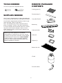
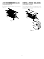
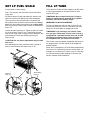
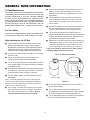
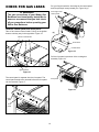
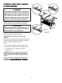
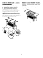
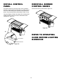
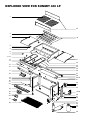
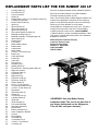
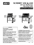
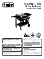
SUMMIT 400 TM LP Gas Barbecues WEB E WEBE R Step-By-Step Guide R CANADIAN GAS ASSOCIATION ® National PROPANEGAS Association WARNING: Follow all leak check procedures carefully in this manual prior to barbecue operation. Do this even if barbecue was dealer assembled. NOTICE TO INSTALLER: These instructions must be left with the owner and the owner should keep them for future use. THIS GAS APPLIANCE IS DESIGNED FOR OUTDOOR USE ONLY. WARNING: Do not try to light this appliance without reading "Lighting" instructions section of this manual. R APPROVED FOR YOUR SAFETY 1. Do not store or use gasoline or other flammable vapors and liquids in the vicinity of this or any other appliance. 2. An LP tank not connected for use shall not be stored in the vicinity of this or any other appliance. FOR YOUR SAFETY If you smell gas: 1. Shut off gas to the appliance. 2. Extinguish any open flame. 3. Open lid. 4. If odor continues, immediately call your gas supplier or your fire department. 97462 10/97 TOOLS NEEDED REMOVE PACKAGED CONTENTS 7/16 inch or open end or adjustable wrench Cooking grates (2) Flavorizer bars (7) SUPPLIES NEEDED Your LP tank is shipped empty for safety. After setting the LP fuel scale you will need to fill it. (See Step "Fill LP tank.") Cozy Heat Zone lid You will need a soap and water solution to check for gas leaks. (See Step "Check for gas leaks.") Note - The hardware size of nuts, bolts and screws is given. For example "1/4-20 x 2 inch bolt" means a bolt 1/4 inch in diameter with 20 threads to the inch, 2 inches long. On a small screw for example, "6-32 x 1/2 inch screw" means a number 6 screw, with 32 threads to the inch, 1/2 inch long. Bottom tray Catch pan holder While we give much attention to our products, unfortunately an occasional error may occur. If a part is missing, do not go back to the store. Call the Weber Customer Service Center toll free 1-888-33-SUMMIT (1-888-337-8664) to receive immediate assistance. Have your owner’s manual and serial number of the barbecue available for reference. Catch pan Drip pan (2) Bottom wire rack LP tank Four tool holders 2 INSTALL FLAVORIZER BARS REINSTALL SPLASH GUARDS You will need: seven flavorizer bars. You will need: two splash guards Set the Flavorizer bars front to back over the burners in the slots of the Flavorizer Bar/cooking grill support. Figure 1(a). The splash guards are already in place. This step is only for reinstallation. Position splash guard, flanges to the rear, at the back of the cooking box assembly. Figure 2 (a). Insert both wire ends into the mounting holes in the cooking box. Figure 2 (b). Flavorizer Bar/cooking grill support Note: You will have to bend the splash guards slightly to fit into the mounting holes. Flavorizer Bar Position the second splash guard, flanges facing you, at the front of the cooking box assembly. Insert both wire ends into the mounting holes in the cooking box. Figure 2. Slot Flanges at the back of the splash guards (a) Splash guards Mounting holes (b) Figure 1 Figure 2 3 REINSTALL SPLASH GUARDS (CONTINUED) ADD COOKING GRATES Splash guards open for use. Figure 3. The cross-rail of the cooking grate goes down. Set the cooking grates in place next to each other. Figure 5. You will need: two cooking grates. Figure 3 Figure 5 Splash guards closed for storage. Figure 4. Figure 4 4 INSTALL BOTTOM TRAY You will need: Bottom tray, catch pan holder, catch pan, and one drip pan. Mounting slots View from front of the Cooking Box Mounting slots Tabs of bottom tray Figure 6 Tabs of bottom tray Note: It may be easier to install the catch pan holder by removing the catch pan from the holder. Hook the ends of the catch pan holder into the hole in the bottom tray. Figure 7. Figure 9 Put the foil drip pan into the catch pan. Figure 7 Slide the bottom tray into the mounting slots under the bottom of the cooking box with the finger grip of the catch pan toward you. Figure 8. CAUTION: Do not line the bottom tray with aluminum foil. It can cause grease fires by trapping the grease and not allowing grease to flow into the catch pan. Figure 8 5 ADD ACCESSORY RACK INSTALL TOOL HOLDERS You will need: accessory rack. You will need: four tool holders. Set the bottom rack between the two bottom connectors. Figure 10. Place the tool holder under the control panel and over the front panel. Figure 11 (a). Set the tool holder on top of the front panel and slide it to the left. Figure 10 (a) Figure 11 6 SET LP FUEL SCALE FILL LP TANK You will need: LP tank (empty). To fill, take the LP tank and filler adapter to an RV center or look up gas-propane in the phone book for other sources of LP gas. Note - For accuracy, the fuel scale must be set with an empty tank. WARNING: We recommend that your LP tank be filled at an authorized LP gas dealer by a qualified attendant, who fills the tank by weight. We utilize various LP tank manufacturers. Some of the tanks we receive have differing top collar assemblies. (The top collar is the metal protective ring around the valve.) One series of tanks mounts with the valve facing front. The other tanks mount with the valve facing away from the fuel scale. These types of tanks are illustrated in Figure 12. IMPROPER FILLING IS DANGEROUS. Tell your LP dealer that this is a new LP tank. The air must be removed from a new LP tank before the initial filling. Your LP tank dealer is equipped to do this. Loosen the tank lock wing nut. Tighten so the lock is held up out of the way. Figure 12 (a). Lift and hook the tank onto the fuel scale. With an empty LP tank, adjust the fuel scale setting to E with scale setting (top) wing nut. Figure 12 (b). WARNING: If you exchange your LP tank, make sure you get a similar tank in return. Your LP tank is equipped with a quick-disconnect valve and an OPD (Overfilling Prevention Device). Other LP tanks are not compatible with your barbecue connection. CAUTION: Do not remove adjustment wing nut from tank scale. The LP tank must be installed, transported and stored in an upright position. LP tank should not be dropped or handled roughly. After adjusting tank scale, push tank down a couple of times to check that the tank scale is set on “E”. Never store or transport the LP tank where temperatures can reach 125° Fahrenheit (too hot to hold by hand – for example: do not leave the LP tank in a car on a hot day). For full instructions on safe handling of LP tanks, see Section "General Tank Information". Scale setting wing nut Tank lock wing nut (a) (b) E E F F Figure 12 7 GENERAL TANK INFORMATION LP Tank Manufacturer The LP tank manufacturer is responsible for the materials, workmanship and performance of the tank. If the tank has a defect, malfunctions, or you have a question regarding the tank, call the tank manufacturer's customer service center. The phone number is on the warning decal which is permanently attached to the tank. If the tank manufacturer has not resolved the issue to your satisfaction, then call Weber-Stephen Products Co., Customer Service Center. ■ Do not use a damaged LP tank. Dented or rusty LP tanks or LP tanks with a damaged valve may be hazardous and should be replaced with a new one immediately. ■ The joint where the hose connects to the LP tank must be tested for leaks each time the LP tank is reconnected. For example, test each time the LP tank is refilled. ■ Be sure the regulator is mounted with the small vent hole pointed downward so it will not collect water. This vent should be free of dirt, grease, bugs etc. ■ The LP tank and connections supplied with your Weber Gas Barbecue have been designed and tested to meet government, American Gas Association and Underwriters Laboratories requirements. ■ Replacement LP tanks supplied by Weber satisfy the requirements. Check to be sure the tank has a D.O.T. certification, and has been tested within five years. Your LP gas supplier can do this for you. Figure 13. For Your Safety Your LP tank is shipped empty for safety. After setting the LP fuel scale you will need to fill it. Refer to Filling your LP tank. Safe handling tips for LP Gas ■ Liquid Propane (LP) gas is a petroleum product as are gasoline and natural gas. LP gas is a gas at regular temperatures and pressures. Under moderate pressure, inside a cylinder, LP gas is a liquid. As the pressure is released the liquid readily vaporizes and becomes gas. ■ LP gas has an odor similar to natural gas. You should know this odor. ■ LP gas is heavier than air. Leaking LP gas may collect in low areas that prevent dispersion. ■ The LP tank must be installed, transported and stored in an upright position. LP tanks should not be dropped or handled roughly. ■ Never store or transport the LP tank where temperatures can reach 125° F (too hot to hold by hand - for example: do not leave the LP tank in a car on a hot day). ■ The LP cylinder supply must be arranged for vapor withdrawal. If you have questions about spare LP tanks, please call Weber-Stephen Customer Service. D.O.T. Certification (example) DOT 4BA240 1/97 20 lb LP tank Note - A refill will last about 20 hours of cooking time at normal use. The fuel scale will indicate the propane supply so you can refill before running out. You do not have to run out before you refill. ■ Date Tested Figure 13 Treat "empty" LP tanks with the same care as when full. Even when the LP tank is empty of liquid there still may be gas pressure in the cylinder. Always close the tank valve before disconnecting. 8 ■ All LP tank supply systems must include a collar to protect the tank valve. ■ The LP tank must be constructed and marked in accordance with the specifications for LP gas cylinders of the U.S. Department of Transportation (D.O.T.). ■ The LP tank shipped with your barbecue is equipped with an OPD (Overfilling Protection Device). CONNECT FILLED LP TANK (a) WARNING: Make sure that the LP tank valve is closed. Close by turning clockwise. Collar Hook the LP tank onto the fuel scale. Loosen the tank lock wing nut. Swing the tank lock down. Tighten the wing nut. Figure 14. Male fitting Tank lock wing nut (b) Hose Tank valve Regulator Valve handwheel close clockwise Pressure relief valve Figure 14 The hose and regulator are connected in the following manner: Tank Slide back the collar of the quick disconnect on the tank valve. Push the male fitting of the regulator into the quick disconnect, and maintain pressure. Slide the collar closed. Figure 15 (a). Figure 15 (b) shows the quick disconnect engaged and various components of the tank and regulator. Regulator vent hole should be at 3, 6, or 9 o'clock. It should not be pointed up. Figure 15 (c). Regulator vent Quick disconnect engaged (c) Turn so regulator vent does not collect water Figure 15 9 CHECK FOR GAS LEAKS Put your fingers under the front edge of the control panel and lift up and pull evenly toward you. Figure 18 (a). WARNING Front edge of the control panel The gas connections of your Weber Gas Barbecue have been factory tested. We do however recommend that you leak check all gas connections before operating your Weber Gas Barbecue. Remove control panel and front panel Take off all 4 burner control knobs. Pull up on the ignition buttons until they stay in the up position. Figure 16. (a) Burner control knobs Front Panel Control Panel Figure 18 Pull the front panel up and out of the cooking box assembly. Figure 19. Ignition button Figure 16 The control panel is separate from the front panel. The control panel needs to be removed before the front panel can be removed. Figure 17. Front panel Figure 19 Control panel Front panel Figure 17 10 CHECK FOR GAS LEAKS (CONTINUED) a) DANGER b) Manifold Do not use an open flame to check for gas leaks. Be sure there are no sparks or open flames in the area while you check for leaks. This will result in a fire or explosion which can cause serious bodily injury or death and damage to property. WARNING: You should check for gas leaks every time you disconnect and reconnect a gas fitting. c) WARNING Make sure all burner control knobs are in the OFF position, including the side burner, if the barbecue has a side burner. Manifold Figure 20 To perform leak checks: Open tank valve by turning the tank valve handwheel counterclockwise. WARNING: Do not ignite burners while leak checking. Check for leaks by wetting the connections with the soap and water solution and watching for bubbles. If bubbles form or if a bubble grows there is a leak. Check: a) Left valves to manifold connection. Figure 20 (a). b) Right valves to manifold connection. Figure 20 (b). c) Corrugated gas line to manifold connection. Figure 20 (c). WARNING: If there is a leak at connection 20 (c) turn OFF the gas and retighten the fitting with a wrench and recheck for leaks with soap and water solution. If a leak persists after retightening the fitting, turn OFF the gas. DO NOT OPERATE THE BARBECUE. Contact your dealer. 11 CHECK FOR GAS LEAKS (CONTINUED) REINSTALL FRONT PANEL You will need: control panel, front panel, and four burner control knobs. a) Hose to regulator connection. Figure 21 (a). With the Weber logo to the left, slide front panel down into place. Figure 22. b) Regulator to tank connection. Figure 21 (b). c) Hose to bracket connection. Figure 21 (c). WARNING: If there is a leak at connections 20 (a), 20 (b), 21 (a), or 21 (b), turn OFF the gas. Do not operate the barbecue. Contact your dealer. WARNING: If there is a leak at connection 21 (c) retighten and recheck for leaks with soap and water. When leak checks are complete, turn gas supply OFF at the source and rinse connections with water. Figure 22 c) b) a) Figure 21 12 INSTALL CONTROL PANEL REINSTALL BURNER CONTROL KNOBS Pull igniter buttons up until they stay in the up position. Place the control panel into the grooves on either side of the front of the cooking box. Push the control panel into place, using even pressure while pushing. Figure 23 (a). Push on the burner control knobs. Figure 24. Use your fingers to lift the front edge of the control panel slightly and set it into the recess on both sides of the cooking box. Figure 23. Figure 24 (a) REFER TO OPERATING GUIDE BEFORE LIGHTING BARBECUE Front Panel Control Panel Figure 23 13 EXPLODED VIEW FOR SUMMIT 400 LP 1 29 2 3 30 4 5 6 7 8-12 13 14 31 32 33 34 35 36 15 16 17 55 37 38 39-40 41 18 19 20 21 22 42 43 44 23 24 45-48 25 26 W 28 W E BE R E BE R 27 49 57 58 50 51 52 53 54 56 REPLACEMENT PARTS LIST THE FOR SUMMIT 400 LP All items are single quantities unless otherwise specified. Parts can be ordered directly from Weber-Stephen Products Company by phone or mail. Note - Do not return parts to Weber-Stephen Products Co. without first contacting the Customer Service Center by phone or mail. Returning the part may not be necessary. While we give much attention to our products, unfortunately an occasional error may occur. If a part is missing, do not go back to the store. Call the Weber Customer Service Center toll free 1-888-33-SUMMIT (1-888-337-8664) to receive immediate assistance. Have your owner’s manual and serial number of the barbecue available for reference. WEBE R Weber-Stephen Products Company Customer Service Center 250 South Hicks Road Palatine, IL 60067-6241 (888) 33-SUMMIT (888-337-8664) E R Cooking grates (2) Flavorizer bars (7) Left work surface Glides (4) Phillips head 1/4-20 x 1 inch machine screws (4) Cooking box assembly Burner control knobs (4) Igniter (2) Igniter lock nut (2) Igniter wire (black) (2) Igniter wire (white) (2) Gas catcher ignition chamber (2) Manifold mounting clips (2) Manifold assembly / Corrugated gas line Igniter buttons (2) Control panel Front panel Match holder bracket Plastic button Caster frame Match holder 1/4-20 x 3 1/2 inch bolt (4) Bottom tray Catch pan holder Casters (2) Catch pan Drip pans (2) Accessory rack Splash guards (2) Flavorizer bar / Cooking grate holders (2) Right work surface Crossover tubes (2) Left burner (2) Right burner (2) Top frame rail #1 (2) Top frame rail #2 (2) Plastic handle (4) #8-16 x 1 inch screw (8) 1/4 inch nylon washers (14) 1/4-20 x 1/2 inch bolts (12) Back panel Wheel hub caps (2) Wheels (2) 1/4-20 wing nuts (2) Cylinder guides (2) Glide axle Glide hubcaps (2) Fuel scale assembly Tank panel assembly Wheel frame Bottom connectors (2) Hose / Regulator / Bracket LP tank Filler adapter Tool holder (4) 1/4-20 keps nut (2) 1/4-20 x 1 3/4 inch bolt 1/4-20 hex nut WEB 1 2 3 4 5 6 7 8 9 10 11 12 13 14 15 16 17 18 19 20 21 22 23 24 25 26 27 28 29 30 31 32 33 34 35 36 37 38 39 40 41 42 43 44 45 46 47 48 49 50 51 52 53 54 55 56 57 58 WARNING: Use only Weber factory authorized parts. The use of any part that is not factory authorized can be dangerous. This will also void your warranty.