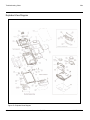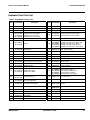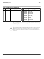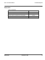
1
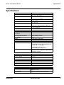
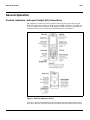
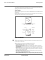
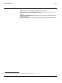
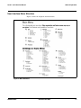
Level 1 and 2 Service Manual
6809501A48-A
V3m
Digital Wireless Telephone
CDMA 1900 MHz, CDMA 800 MHz
MOTOROLA and the Stylized M Logo are registered in the US Patent & Trademark Office.
All other product or service names are the property of their respective owners.
The Bluetooth trademarks are owned by their proprietor and used by Motorola, Inc. under license.
© Motorola, Inc. 2006.
All rights reserved.
Mobile Devices Business,
Sawgrass International Concourse
789 International Parkway
Room S2C
Sunrise, FL 33325-6220
Level 1 and 2 Service Manual
1 and 2
Contents
V3m
6809501A48-A
Contents
Contents
Introduction . . . . . . . . . . . . . . . . . . . . . . . . . . . . . . . . . . . . . . . . . . . . . . . . . . . . . . . . . . . . . . . . . . . . . . . . . . . . . . . . . 5
Product Identification . . . . . . . . . . . . . . . . . . . . . . . . . . . . . . . . . . . . . . . . . . . . . . . . . . . . . . . . . . . . . . . . . . . 5
Product Names . . . . . . . . . . . . . . . . . . . . . . . . . . . . . . . . . . . . . . . . . . . . . . . . . . . . . . . . . . . . . . . . . . . . . . . . 5
Regulatory Agency Compliance . . . . . . . . . . . . . . . . . . . . . . . . . . . . . . . . . . . . . . . . . . . . . . . . . . . . . . . . . . . 5
Computer Program Copyrights . . . . . . . . . . . . . . . . . . . . . . . . . . . . . . . . . . . . . . . . . . . . . . . . . . . . . . . . . . . 6
About this Service Manual . . . . . . . . . . . . . . . . . . . . . . . . . . . . . . . . . . . . . . . . . . . . . . . . . . . . . . . . . . . . . . . 6
Warranty Service Policy . . . . . . . . . . . . . . . . . . . . . . . . . . . . . . . . . . . . . . . . . . . . . . . . . . . . . . . . . . . . . . . . . 7
Parts Replacement . . . . . . . . . . . . . . . . . . . . . . . . . . . . . . . . . . . . . . . . . . . . . . . . . . . . . . . . . . . . . . . . . . . . . 7
Specifications . . . . . . . . . . . . . . . . . . . . . . . . . . . . . . . . . . . . . . . . . . . . . . . . . . . . . . . . . . . . . . . . . . . . . . . . . . . . . . 9
Product Overview . . . . . . . . . . . . . . . . . . . . . . . . . . . . . . . . . . . . . . . . . . . . . . . . . . . . . . . . . . . . . . . . . . . . . . . . . . . 10
Features . . . . . . . . . . . . . . . . . . . . . . . . . . . . . . . . . . . . . . . . . . . . . . . . . . . . . . . . . . . . . . . . . . . . . . . . . . . . . 10
General Operation . . . . . . . . . . . . . . . . . . . . . . . . . . . . . . . . . . . . . . . . . . . . . . . . . . . . . . . . . . . . . . . . . . . . . . . . . . . 12
Controls, Indicators, and Input / Output (I/O) Connections . . . . . . . . . . . . . . . . . . . . . . . . . . . . . . . . . . . . 12
User Interface Menu Structure . . . . . . . . . . . . . . . . . . . . . . . . . . . . . . . . . . . . . . . . . . . . . . . . . . . . . . . . . . 15
Alert Settings . . . . . . . . . . . . . . . . . . . . . . . . . . . . . . . . . . . . . . . . . . . . . . . . . . . . . . . . . . . . . . . . . . . . . . . . 16
Battery Function . . . . . . . . . . . . . . . . . . . . . . . . . . . . . . . . . . . . . . . . . . . . . . . . . . . . . . . . . . . . . . . . . . . . . . 16
Operation . . . . . . . . . . . . . . . . . . . . . . . . . . . . . . . . . . . . . . . . . . . . . . . . . . . . . . . . . . . . . . . . . . . . . . . . . . . . 16
Tools and Test Equipment . . . . . . . . . . . . . . . . . . . . . . . . . . . . . . . . . . . . . . . . . . . . . . . . . . . . . . . . . . . . . . . . . . . . 17
Disassembly . . . . . . . . . . . . . . . . . . . . . . . . . . . . . . . . . . . . . . . . . . . . . . . . . . . . . . . . . . . . . . . . . . . . . . . . . . . . . . . . 18
Removing and Replacing the Battery Cover and Battery . . . . . . . . . . . . . . . . . . . . . . . . . . . . . . . . . . . . . 18
Removing and Replacing the Memory Card . . . . . . . . . . . . . . . . . . . . . . . . . . . . . . . . . . . . . . . . . . . . . . . . 20
Removing and Replacing the Rear Housing . . . . . . . . . . . . . . . . . . . . . . . . . . . . . . . . . . . . . . . . . . . . . . . . 21
Removing and Replacing the Antenna . . . . . . . . . . . . . . . . . . . . . . . . . . . . . . . . . . . . . . . . . . . . . . . . . . . . 25
Removing and Replacing the Transceiver Board Assembly . . . . . . . . . . . . . . . . . . . . . . . . . . . . . . . . . . . 27
Removing and Replacing the Flip Assembly Cover and CLI Lens . . . . . . . . . . . . . . . . . . . . . . . . . . . . . . . 28
Removing and Replacing the Camera Assembly . . . . . . . . . . . . . . . . . . . . . . . . . . . . . . . . . . . . . . . . . . . . . 37
Removing and Replacing the Display Module Assembly . . . . . . . . . . . . . . . . . . . . . . . . . . . . . . . . . . . . . . 38
Removing and Replacing the Hinge Assembly . . . . . . . . . . . . . . . . . . . . . . . . . . . . . . . . . . . . . . . . . . . . . . . . . . . 40
Phone Identification . . . . . . . . . . . . . . . . . . . . . . . . . . . . . . . . . . . . . . . . . . . . . . . . . . . . . . . . . . . . . . . . . . . . . . . . . 56
Personality Transfer . . . . . . . . . . . . . . . . . . . . . . . . . . . . . . . . . . . . . . . . . . . . . . . . . . . . . . . . . . . . . . . . . . . 56
Identification . . . . . . . . . . . . . . . . . . . . . . . . . . . . . . . . . . . . . . . . . . . . . . . . . . . . . . . . . . . . . . . . . . . . . . . . . 56
Troubleshooting Chart . . . . . . . . . . . . . . . . . . . . . . . . . . . . . . . . . . . . . . . . . . . . . . . . . . . . . . . . . . . . . . . . . . . . . . . 57
Programming: Software Upgrade and Flexing . . . . . . . . . . . . . . . . . . . . . . . . . . . . . . . . . . . . . . . . . . . . . . 59
Part Numbers . . . . . . . . . . . . . . . . . . . . . . . . . . . . . . . . . . . . . . . . . . . . . . . . . . . . . . . . . . . . . . . . . . . . . . . . 59
Related Publications . . . . . . . . . . . . . . . . . . . . . . . . . . . . . . . . . . . . . . . . . . . . . . . . . . . . . . . . . . . . . . . . . . . 59
Exploded View Diagram . . . . . . . . . . . . . . . . . . . . . . . . . . . . . . . . . . . . . . . . . . . . . . . . . . . . . . . . . . . . . . . . 60
Exploded View Parts List . . . . . . . . . . . . . . . . . . . . . . . . . . . . . . . . . . . . . . . . . . . . . . . . . . . . . . . . . . . . . . 61
Accessories . . . . . . . . . . . . . . . . . . . . . . . . . . . . . . . . . . . . . . . . . . . . . . . . . . . . . . . . . . . . . . . . . . . . . . . . . . . 63
6809501A48-A
November 03, 2006
3
Contents
4
V3m
November 03, 2006
6809501A48-A
Level 1 and 2 Service Manual
1 and 2
V3m
6809501A48-A
Introduction
Introduction
Motorola® Inc. maintains a worldwide organization that is dedicated to provide
responsive, full-service customer support. Motorola products are serviced by an
international network of company-operated product-care centers as well as
authorized independent service firms.
Available on a contract basis, Motorola Inc. offers comprehensive maintenance and
installation programs that enable customers to meet requirements for reliable,
continuous communications.
To learn more about the wide range of Motorola service programs, contact your local
Motorola products representative or the nearest Customer Service Manager.
Product Identification
Motorola products are identified by the model number on the housing. Use the entire
model number when inquiring about the product. Numbers are also assigned to
chassis and kits. Use these numbers when requesting information or ordering
replacement parts.
Product Names
Product names are subject to change without notice. Some product names, as well
as some frequency bands, are available only in certain markets.
Regulatory Agency Compliance
This device complies with Part 15 of the FCC Rules. Operation is subject to the
following conditions:
• This device may not cause any harmful interference
• This device must accept interference received, including interference that may
cause undesired operation
This class B device also complies with all requirements of the Canadian
Interference-Causing Equipment Regulations (ICES-003).
Cet appareil numérique de la classe B respecte toutes les exigences du Règlement
sur le matériel brouilleur du Canada.
6809501A48-A
November 03, 2006
5
Introduction
V3m
Computer Program Copyrights
The Motorola products described in this manual may include Motorola computer
programs stored in semiconductor memories or other media that are copyrighted
with all rights reserved worldwide to Motorola. Laws in the United States and other
countries preserve for Motorola, Inc. certain exclusive rights to the copyrighted
computer programs, including the exclusive right to copy, reproduce, modify,
decompile, disassemble, and reverse-engineer the Motorola computer programs in
any manner or form without Motorola's prior written consent. Furthermore, the
purchase of Motorola products shall not be deemed to grant either directly or by
implication, estoppel, or otherwise, any license or rights under the copyrights,
patents, or patent applications of Motorola, except for a nonexclusive license to use
the Motorola product and the Motorola computer programs with the Motorola
product.
About this Service Manual
Using this service manual and the suggestions contained in it assures proper
installation, operation, and maintenance. Refer questions about this manual to the
nearest Customer Service Manager.
Audience
This service manual aids service personnel in testing and repairing V3m
telephones. Service personnel should be familiar with electronic assembly, testing,
and troubleshooting methods, and with the operation and use of associated test
equipment.
Use of this manual assures proper installation, operation, and maintenance of
Motorola products and equipment. It contains all service information required for
the equipment described and is current as of the printing date.
Scope
This manual provides basic information relating to V3m telephones, and also to
provides procedures and processes for repairing the units at Level 1 and 2 service
centers including:
• Unit swap out
• Repairing of mechanical faults
• Basic modular troubleshooting
• Testing and verification of unit functionality
• Initiate warranty claims and send faulty modules to Level 3 or 4 repair
centers
6
November 03, 2006
6809501A48-A
Level 1 and 2 Service Manual
Introduction
Conventions
The following special characters and typefaces are used in this manual to emphasize
certain types of information.
➧
G
E
Note: Emphasizes additional information pertinent to the subject
matter.
Caution: Emphasizes information about actions that may result in
equipment damage.
Warning: Emphasizes information about actions that may result in
personal injury.
Warranty Service Policy
The product is sold with the standard 12-month warranty terms and conditions.
Accidental damage, misuse, and extended warranties offered by retailers are not
supported under warranty. Non warranty repairs are available at agreed fixed
repair prices.
Out-of-Box Failure Policy
The standard out of box failure criteria applies. Customer units that fail very early
on after the date of sale, are to be returned to Manufacturing for root cause analysis,
to guard against epidemic criteria. Manufacturing will bear the costs of early life
failure.
Product Support
Customer’s original units will be repaired but not refurbished as standard.
Appointed Motorola Service Hubs will perform warranty and non-warranty field
service for level 2 (assemblies) and level 3 (limited PCB component). The Motorola
High Technology Centers will perform level 4 (full component) repairs.
Customer Support
Customer support is available through dedicated Call Centers and in-country help
desks. Product Service training is available through the local Motorola Support
Center.
Parts Replacement
When ordering replacement parts or equipment, include the Motorola part number
and description used in the service manual or supplement.
When the Motorola part number of a component is not known, use the product model
number or other related major assembly along with a description of the related
major assembly and of the component in question.
In the U.S.A., to contact Motorola, Inc. on your TTY, call: 800-793-7834
6809501A48-A
November 03, 2006
7
Introduction
V3m
Accessories and Aftermarket Division (AAD)
Order replacement parts, test equipment, and manuals from AAD.
U.S.A.
Outside U.S.A.
Phone: 800-814-0601
Phone: 847-538-8023
FAX: 800-622-6210
FAX: 847-576-3023
Website: http://businessonline.motorola.com
EMEA
Phone: +49 461 803 1404
Website: http://emeaonline.motorola.com
Asia
Phone: +65 648 62995
Website: http://asiaonline.motorola.com
8
November 03, 2006
6809501A48-A
Level 1 and 2 Service Manual
Specifications
Specifications
General Function
Frequency Range 1900 MHz PCS
Frequency Range 800 MHz CDMA
Channel Spacing
Channels
Modulation
Duplex Spacing
Frequency Stability
Power Supply
Average Transmit Current
Average Stand-by Current
(slot cycle 1)
Dimensions
(with 740 mAh Li Ion battery)
Size (Volume)
Weight
Operating Temperature Range
Humidity
Battery Life, 740 mAh Li Ion Battery
Specification
1931.250 -1988.750 MHz Rx
1851.250 -1908.750 MHz Tx
869.70 - 893.31 Rx (CDMA)
824.70 - 848.31 Tx (CDMA)
50 kHz PCS
30 kHz CDMA
1150 PCS
788 CDMA 800
1M25F9W (1.25 MHz bandwidth) CDMA
3G1XRTT (1.25 MHz bandwidth) CDMA-1X
80 MHz PCS
45 MHz CDMA 800
± 150 Hz (CDMA)
3.6V Li Ion 740 mAh battery
310 mA at +13dBm)
4.18 mA
53mm x 98mm x 14.5mm
67 cc
<115g (3.88 oz) with battery
-30° C to +60° C (-22° F to +140° F)
80% Relative Humidity at 50° C (122° F)
Digital Talk Time: 180 Minutes for 740mAh and
(IS95/IS2000 Cell/PCS, CDG Suburban Profile
with 40% VAF ~ + 110.6dBm)
Digital Standby Time: 195 Hours
(IS95/IS2000 Cell/PCS Slot Cycle 1)
All talk and standby times are approximate and
depend on network configuration, signal strength,
and features selected.
Transmitter Function
RF Power Output
Spurious Emissions
Input/Output Impedance
Transmit Audio Response
Modulation
CDMA Transmit Waveform Quality
(Rho)
Receiver Function
Receive Sensitivity
Audio Distortion
6809501A48-A
Specification
0.30 watts +25 dBm into 50 ohms (CDMA/PCS
nominal)
- 18.5 dBm (max) from 0.03 to 19 GHz
50 ohms (nominal)
6 dBm/octave pre-emphasis
1M25F9W (1.25 MHz bandwidth) CDMA
0.94
Specification
-116 dBm -104 dBm (CDMA/PCS, 0.5% Static
FER) 0.5% or less
Less than 5% at 1004 Hz, +/- 8 kHz peak
frequency deviation (transmit and receive)
November 03, 2006
9
Product Overview
V3m
Product Overview
Motorola V3m mobile telephones feature Code Division Multiple Access (CDMA)
technology. The mobile telephone uses a simplified icon and Graphical user
interface (GUI) for easier operation, allow Short Message Service (SMS) text
messaging, and include clock, alarm, datebook, calculator, and caller profiling
personal management tools. The V3m telephones include a built in camera. The
phone provides 32 Embedded ring tones including VibraCall vibrating alert and 32
Downloadable/Customizable iMelody ring tones. The V3m telephones are dual band
that allows roaming within the CDMA 800 MHz and PCS 1900 MHz bands.
The V3m CDMA phones consist of a main housing assembly and a flip assembly.
The main circuit board, battery, headset jack, and accessory connector are located
in the main housing assembly. The camera on the V3m phones is located in the
hinged flip assembly.
The flip assembly contains the entire hinge mechanism. It is attached to the main
housing by four screws. The main display is on the inside of the flip assembly and
a one line LED display on the outside of the flip assembly. The main display on the
V3m phones is a 176 x 220 pixel 65k TFT LCD. The external CLI display is a 96 x
80 pixel 65K CSTN LCD. The camera module is a 1.3 mega-pixel, VGA CMOS
camera.
The main housing assembly includes a battery cover, chassis, main circuit board,
keypad plastic front housing, and internal antenna.
The main circuit board contains the Receiver, Transmitter, Synthesizer and Control
Logic Circuitry which together comprise the dual band tri-mode phone electronics.
The telephones are made of polycarbonate plastic. The display and speaker, as well
as the 18-key keypad, transceiver printed-circuit board (PCB), microphone, charger
and headphone connectors, and power button are contained within the flip formfactor housing. The 740 mAh Lithium Ion (Li Ion) battery provides up to 180
minutes of talk time in CDMA mode with up to 195 hours of standby time1.
Features
V3m telephones use advanced, self-contained, sealed, custom integrated circuits to
perform the complex functions required for CDMA communication. Aside from the
space and weight advantage, microcircuits enhance basic reliability, simplify
maintenance, and provide a wide variety of operational functions.
Features available in this family of telephones include:
• Built in VGA Camera (1.3 Mega-pixel)
• Video capture and playback
• 65K Thin Film Transistor (TFT) Active Color Display
• External color CLI Display
• Enhanced VST - Speaker independent calling
• Speaker Phone
• Stereo Headset support
• Class 2 Bluetooth®
• 23MB User Memory
• Micro-SD removable memory
1. All talk and standby times are approximate and depend on network configuration, signal strength, and features selected.
10
November 03, 2006
6809501A48-A
Level 1 and 2 Service Manual
Product Overview
Wireless Access Protocol (WAP) 1.1 Compliancy
In the WAP environment, access to the Internet is initiated in wireless markup
language (WML), which is derived from hypertext markup language (HTML). The
request is passed to a WAP gateway, which retrieves the information from the
server in standard HTML (subsequently filtered to WML) or directly in WML, if
available. The information is then passed to the mobile subscriber via the mobile
network.
The microbrowser can be configured for baud, idle timeout, line type, phone number,
and connection type.
➧
Bitmap image data will download as text. If the image is larger than the screen,
only part of the image will display.
➧
When the user receives a call while in browser mode, the browser will pause and
allow the user to resume after completing the call.
Simplified Text Entry
There are three different ways to enter text using the phone keypad:
• iTAP™ predictive text entry. Press a key to generate a character and a
dynamic dictionary uses this to build and display a set of word or name
options. The iTAP™ feature may not be available on the phone in all languages.
• Tap. Press a key to generate a character.
• Numeric. The keypad produces numeric characters only. For some text areas
this is the only method available; for example, phone numbers.
Caller Line Identification
Upon receipt of a call, the calling party’s phone number is compared to the phone
book. If the number matches a phone book entry, that name will be displayed. If
there is no phone book entry, the incoming phone number will be displayed. In the
event that no caller identification information is available, the Incoming Call
message is displayed.
➧
User must subscribe to a caller line identification service through their service
provider.
Other Features
Detailed descriptions of these and other features can be found in the appropriate
user’s guide listed in the “Related Publications” section toward the end of this
manual.
6809501A48-A
November 03, 2006
11
General Operation
V3m
General Operation
Controls, Indicators, and Input / Output (I/O) Connections
The telephone’s controls are located on the sides of the flip and on the keypad.
Indicators, in the form of icons, are displayed on the LCD (see Figure 2). V3m phones
have an audible alert transducer at the bottom and I/O connectors, consisting of a
charger/accessory port, located on the side of the phone. See Figure 1.
051355o/051356o
Figure 1. Controls, indicators, and I/O
“Soft keys” refer to non-labeled keys that correspond to text options displayed on
the screen. The left and right soft keys perform the function shown in the corners
12
November 03, 2006
6809501A48-A
Level 1 and 2 Service Manual
General Operation
of the display. The right key will usually select an option whereas the left key will
usually exit a function or return to a previous screen.
Color Display
The V3m wireless phones feature a 65k color Thin Film Transistor (TFT) 176 x 220
pixel display.
Display animation makes the phone’s menus move smoothly as the user scrolls up
and down. Turn animation off to conserve the battery.
051358o/051359o
Figure 2. Icon Indicators
➧
Whether a phone displays all indicators depends on the programming and services
to which the user subscribes.
Figure 2 shows some common icons displayed on the LCD.
• In Use Indicator. Appears when a call is in progress.
• Signal Strength Indicator. Shows the strength of the phone’s connection
with the network. Calls cannot be sent or received when the “no signal” indicator is displayed.
• Roam Indicator. Appears when the phone uses another network system outside the user’s home network. When leaving the home network area, the phone
roams, or seeks another network.
• Message Waiting Indicator. Appears when the phone receives a text message. This is a network-dependent feature.
• Battery Level Indicator. Shows the amount of charge left in the battery. The
more segments visible, the greater the charge. Recharge the battery as soon as
6809501A48-A
November 03, 2006
13
General Operation
V3m
•
•
•
•
possible when the Low Battery warning message appears.
Voice Message Waiting Indicator.2 Appears when a voicemail message is
received. This is a network-dependent feature.
menu.
Alert Setting Indicator. Shows the current selected alert. The default alert
setting is a ringer.
GPS Indicator. Shows when your phone can send location information # or not
$.
2. Network, subscription service provider dependent feature. Not available in all areas.
14
November 03, 2006
6809501A48-A
Level 1 and 2 Service Manual
General Operation
User Interface Menu Structure
Figure 3 shows the telephone menu structure.
051357o/051360
Figure 3. Menu Structure
6809501A48-A
November 03, 2006
15
General Operation
V3m
Alert Settings
V3m telephones include up to 32 preset alert tones and vibrations that can be
applied to all alert events at the same time.
➧
Pressing either volume key will mute the alert.
Battery Function
Battery Gauge
The telephone displays a battery level indicator icon in the idle screen to indicate
the battery charge level. The gauge shows four levels: 100%, 66%, 33%, and Low
Battery.
Battery Removal
Removing the battery causes the device to immediately shut down and any pending
work (for example, partially entered phone book entries or outgoing messages) is
lost.
➧
G
To ensure proper memory retention, turn OFF the phone before removing the
battery. Immediately replace the old battery with a fresh battery.
If the battery is removed while receiving a message, the message will be lost.
Operation
For detailed operating instructions, refer to the appropriate User’s Guide listed in
the Related Publications section toward the end of this manual.
16
November 03, 2006
6809501A48-A
1 and 2
V3m
6809501A48-A
Level 1 and 2 Service Manual
Tools and Test Equipment
Tools and Test Equipment
The following table lists tools and test equipment recommended for disassembly
and reassembly of V3m telephones. Use either the listed items or equivalents.
Table 1. General Test Equipment and Tools
Motorola Part Number1
RSX4043-A
Description
Application
Torque Driver
Used to remove and replace screws
Torque Driver Bit T-5, Apex 440-6IP Torx
Plus or equivalent
Used with torque driver
T-3 Bit
Used with torque driver
See Table 7
Rapid Charger
Used to charge battery and to power
device
0180386A82
Antistatic Mat Kit (includes 66-80387A95
antistatic mat, 66-80334B36 ground
cord, and 42-80385A59 wrist band)
Provides protection from damage to
device caused by electrostatic discharge
(ESD)
0-00-00-30005
Disassembly tool, plastic with flat and
pointed ends (manual opening tool) from
AMS
Used during assembly/disassembly of
device
Tweezers, plastic
Used during assembly/disassembly
Digital Multimeter, HP34401A2
Used to measure battery voltage
—
—
1. To order in North America, contact Motorola Aftermarket and Accessories Division (AAD) at (800) 814-0601 or
FAX (800) 622-6210; Internationally, AAD can be reached by calling (847) 538-8023 or faxing (847) 576-3023.
2. Not available from Motorola. To order, contact Hewlett Packard at (800) 452-4844.
AMS Software & Elektronik Gmbh
c/o Holger Grube
Lise-Meitner-Straße 9
D-24914 Flensburg Tel.: +49-461-90398-0
Fax: +49-461-90398-50
6809501A48-A
November 03, 2006
17
Disassembly
V3m
Disassembly
The procedures in this section provide instructions for the disassembly of V3m
telephones. Tools and equipment used for the phone are listed in Table 1, preceding.
G
G
Many of the integrated devices used in this equipment are vulnerable to damage
from electrostatic discharge (ESD). Ensure adequate static protection is in place
when handling, shipping, and servicing the internal components of this equipment.
Avoid stressing the plastic in any way to avoid damage to either the plastic or
internal components.
Removing and Replacing the Battery Cover and Battery
E
All batteries can cause property damage and/or bodily injury, such as burns if a
conductive material, such as jewelry, keys, or beaded chains touch exposed terminals. The conductive material may complete an electrical circuit (short circuit) and
become quite hot. Exercise care in handling any charged battery, particularly when
placing it inside a pocket, purse, or other container with metal objects.
1.
2.
Ensure the phone is turned off.
Press in and hold the battery door latch as shown in Figure 1.
Latch
Battery Door
051341o
Figure 1. Removing the Battery Cover
3.
18
Rotate the battery cover upward and lift it completely off the phone.
November 03, 2006
6809501A48-A
Level 1 and 2 Service Manual
Disassembly
4.
Lift the end of the battery first, then remove it from the phone. See Figure 2.
Battery
060658o
Figure 2. Removing the battery
E
There is a danger of explosion if the Lithium Ion battery is replaced incorrectly.
Replace only with the same type of battery or equivalent as recommended by the
battery manufacturer. Dispose of used batteries according to the manufacturer’s
instructions.
5.
6.
7.
6809501A48-A
To replace, Align the battery with the battery compartment so the contacts on
the battery match the battery contacts in the phone.
Insert the battery, contacts side first, into the battery compartment and push
down followed by the opposite edge of the battery.
Insert the bottom edge of the of the battery cover into the rear housing, then
push the top edge of the cover down and snap it into place.
November 03, 2006
19
Disassembly
V3m
Removing and Replacing the Memory Card
1.
2.
Remove the battery cover, and battery as described in the procedures.
Slide the memory card out of the memory card slot as shown in Figure 3.
Memory card
060658o
Figure 3. Removing the Memory Card
3.
4.
20
To replace, slide the memory card (contacts facing down) all the way into the
memory card slot.
Replace the battery and the battery cover as described in the procedures.
November 03, 2006
6809501A48-A
Level 1 and 2 Service Manual
Disassembly
Removing and Replacing the Rear Housing
G
This product contains static-sensitive devices. Use anti-static handling procedures
to prevent electrostatic discharge (ESD) and component damage.
1.
G
Remove the battery cover, battery, and memory card as described in the
procedures.
In addition to 2 screws, the rear housing assembly is fastened with plastic latches.
These are fragile and should be released with care.
2.
Using a Torx driver with a T-6 bit, remove the screws at each side of the phone.
Retain the screws for reassembly. See Figure 4.
Screw
Battery Insulator
Screw
051343o
Figure 4. Removing the Rear Housing Screws
6809501A48-A
November 03, 2006
21
Disassembly
V3m
3.
Use the plastic tweezers to remove the battery insulating material on the right
side of the battery compartment. Do not reuse the battery insulating material
for reassembly.
Battery Insulator
051343o
Figure 5. Removing the Rear Housing Screws
22
November 03, 2006
6809501A48-A
Level 1 and 2 Service Manual
Disassembly
4.
Release the 4 housing latches by inserting the pointed end of the plastic
disassembly tool into the openings on the rear housing.
Latches
Latches
051344o
Figure 6. Removing the Rear Housing Latches
5.
Carefully rotate the rear housing away from the front housing and flip
assembly.
Keypad flex connector
Display flex connector
060662o
Figure 7. Removing the Rear Housing Assembly
6809501A48-A
November 03, 2006
23
Disassembly
V3m
G
The flexible printed cable (FPC) (flex) is easily damaged. Exercise extreme care when
handling.
6.
7.
8.
9.
10.
11.
12.
13.
14.
24
Use the disassembly tool to unseat the display flex connector and the keypad
flex connector from their sockets.
Lift the rear housing assembly away from the phone.
To replace, carefully align the display flex connector to it’s socket on the rear
housing assembly, then gently press down on the flex connector until it is
properly seated in it’s socket.
Carefully align the keypad flex connector to it’s socket on the rear housing
assembly, then gently press down on the flex connector until it is properly
seated in it’s socket.
Rotate the rear housing assembly so it sits over the phone.
Align the housing latches with the corresponding openings on the front
housing. Gently press the housings together until the catches snap into place.
Cover the display flex with new battery insulator material. Do not reuse the
old battery insulating material.
Replace the 2 housing screws and tighten to a final torque setting of 24 Ncm
(2.2 inch pounds). Do not over tighten.
Replace the antenna, battery, and battery cover as described in the procedures.
November 03, 2006
6809501A48-A
Level 1 and 2 Service Manual
Disassembly
Removing and Replacing the Antenna
1.
2.
Remove the battery cover, battery, and rear housing assembly as described in
the procedures.
Use the metal tweezers to grasp the rubber antenna grommets and carefully
remove them from the antenna assembly. See Figure 8. Set the rubber
grommets aside for reuse.
Tweezers
Grommets
051346o
Figure 8. Removing the Antenna Grommets
6809501A48-A
November 03, 2006
25
Disassembly
V3m
3.
Use the disassembly tool to release the antenna assembly starting from the
right side as shown in Figure 9.
Antenna assembly
060663o
Figure 9. Removing the Antenna Assembly
4.
5.
6.
7.
8.
26
Carefully lift the antenna assembly away from the phone.
To replace, align the antenna assembly to the phone.
Carefully press the antenna assembly into position starting from the left side
until the antenna assembly latches snap into position.
Reinstall the rubber antenna assembly grommets into their slots. Each
antenna grommet is uniquely shaped to fit into its respective position.
Replace the rear housing assembly, battery and battery cover as described in
the procedures.
November 03, 2006
6809501A48-A
Level 1 and 2 Service Manual
Disassembly
Removing and Replacing the Transceiver Board Assembly
G
This product contains static-sensitive devices. Use anti-static handling procedures
to prevent electrostatic discharge (ESD) and component damage.
1.
2.
Remove the battery cover, battery, antenna, rear housing and battery tray as
described in the procedures.
Lift the transceiver board assembly out of the front housing with the
disassembly tool. See Figure 10.
PC Board
Disassembly Tool
051348a
Figure 10. Removing the Transceiver PC board Assembly
3.
4.
5.
6809501A48-A
To replace, insert the transceiver board assembly into the rear housing.
Carefully and gently press the transceiver board into position and until it snaps
into place.
Replace the antenna assembly, rear housing, battery, and battery cover as
described in the procedures.
November 03, 2006
27
Disassembly
V3m
Removing and Replacing the Flip Assembly Cover and CLI Lens
1.
2.
3.
Remove the battery cover, battery, antenna, rear housing, and transceiver
board assembly as described in the procedures.
Remove the 4 flip assembly screw caps.
Use the T-5 driver to remove the 4 screws from the flip assembly (see Figure
11). Retain the screws for re-assembly.
Screw Caps
Screw Caps
Screws
Screws
051349/051350o
Figure 11. Removing the Flip Assembly Screws
4.
28
Before removing the flip cover, note the locations of the smart buttons on the
sides of the flip assembly.
November 03, 2006
6809501A48-A
Level 1 and 2 Service Manual
Disassembly
5.
Use the disassembly tool to gently pry off the flip cover (see Figure 12).
Flip Cover
Disassembly Tool
051351o
Figure 12. Separating the Flip Assembly Cover
6.
7.
8.
6809501A48-A
Remove the smart buttons on the side of the flip assembly. Set them aside for
reassembly.
Lift the flip cover away from the flip assembly. Be careful not to damage the
display flex cable.
Slide the flat end of the plastic disassembly tool, between the lens and the metal
frame.
November 03, 2006
29
Disassembly
V3m
9.
Slowly rotate the plastic disassembly tool by 90° (see Figure 13).
CLI lens
Disassembly tool
062020o
Figure 13. CLI Lens Removal
10. Carefully lift up the CLI Lens from the display module assembly.
11. Carefully use the plastic tool remove any remaining glue.
G
30
Do not use any kind of liquid or spray to remove the remaining glue.
November 03, 2006
6809501A48-A
Level 1 and 2 Service Manual
Disassembly
12. To replace, align CLI lens to the Flip Outer Assembly. Move the CLI lens to
the opening. Ensure that the liner is overlapping the inside surface. The CLI
lens fits in one direction only (see Figure 14).
CLI lens
(liner facing up)
Flip outer assembly
062026o
Figure 14. CLI Lens Replacement
13. Expose the adhesive surface of the new CLI lens and attach the replacement
CLI lens to the flip outer assembly.
6809501A48-A
November 03, 2006
31
Disassembly
V3m
14. Align CLI lens to the flip outer assembly and lightly press the low tech film
around the CLI. opening (see Figure 15).
062027o
Figure 15. Flip CLI Lens Placement
32
November 03, 2006
6809501A48-A
Level 1 and 2 Service Manual
Disassembly
15. Align the top, left and right sides of the flip cover and press into position (see
Figure 16).
062028o
Figure 16. Flip Cover Replacement, Top, Left and Right Sides
6809501A48-A
November 03, 2006
33
Disassembly
V3m
16. Apply pressure at the corners of the CLI Lens for 3 seconds to insure good
adhesion (see Figure 17).
062032o
Figure 17. Flip CLI Lens Replacement
34
November 03, 2006
6809501A48-A
Level 1 and 2 Service Manual
Disassembly
17. Insert and tighten the 4 screws to 1.5 in lbs to secure the flip cover to the flip
assembly. Avoid damage to the flex cable (see Figure 18).
062040o
Figure 18. Flip Screws Replacement
6809501A48-A
November 03, 2006
35
Disassembly
V3m
18. Insert the 4 rubber screw caps over the flip assembly screws (see Figure 19).
062041o
Figure 19. Flip Screw Cap Replacement
19. Replace the transceiver board assembly, rear housing, antenna assembly,
battery, and battery cover as described in the procedures.
36
November 03, 2006
6809501A48-A
Level 1 and 2 Service Manual
Disassembly
Removing and Replacing the Camera Assembly
1.
G
Remove the battery cover, battery, antenna, rear housing, and transceiver
board assembly, flip assembly cover, and CLI lens cover as described in the
procedures.
The flexible printed cable (FPC) (flex) is easily damaged. Exercise extreme care when
handling.
2.
3.
Unlock the ZIF connector and remove the camera assembly flex connector.
Carefully lift the camera assembly and flex out of the flip assembly (see
Figure 20).
Camera Assembly
Disassembly Tool
ZIF Connector
051352a
Figure 20. Camera Assembly Removal
4.
5.
6.
6809501A48-A
To replace, carefully press the camera assembly into its slot in the flip
assembly.
Insert the end of the camera assembly flex cable into its slot in the ZIF
connector on the flip display assembly. Avoid damage to the flex cable.
Replace the flip assembly cover, transceiver board, rear housing, antenna,
battery, and battery cover as described in the procedures.
November 03, 2006
37
Disassembly
V3m
Removing and Replacing the Display Module Assembly
1.
G
Remove the battery cover, battery, rear housing, antenna, transceiver board
assembly, flip assembly cover, and camera assembly, as described in the
procedures.
The flexible printed cable (FPC) (flex) is easily damaged. Exercise extreme care when
handling.
2.
Use the disassembly tool to unseat the display module assembly flex connector
from its socket (see Figure 21).
Display Flex Connector
Disassembly Tool
051353o
Figure 21. Display Module Assembly Flex Connector
3.
4.
38
Carefully and gently lift one corner of the display module assembly out of the
flip assembly.
Avoid damage to the electrical components on the flex while carefully removing
the display module assembly from the flip assembly.
November 03, 2006
6809501A48-A
Level 1 and 2 Service Manual
Disassembly
5.
Carefully lift the display assembly away from the flip assembly (see Figure 22).
Display Assembly
Disassembly Tool
Figure 22. Removing the Display Module Assembly
6.
7.
8.
9.
6809501A48-A
To replace, align the display module assembly to the flip assembly.
Carefully lower the display module into the flip assembly. Ensure that all of
the display none of the display assembly components are damaged.
align the flip display flex to the flex connector on the flip display assembly and
gently press down on the flex connector until properly seated.
Replace the camera assembly, flip assembly cover, transceiver board, rear
housing, antenna, battery, and battery connector as described in the
procedures.
November 03, 2006
39
Removing and Replacing the Hinge Assembly
V3m
Removing and Replacing the Hinge Assembly
1.
Carefully lift up the grounding flip boot strap (see Figure 23).
Grounding Flip Boot Strap
062042o
Figure 23. Lifting the Grounding Flip Boot Strap
G
The flexible printed cable (FPC) (flex) is easily damaged. Exercise extreme care when
handling.
2.
Use the disassembly tool to unseat the display module assembly flex connector
from its socket (see Figure 24).
Flex connector
062000o
Figure 24. Display Module Assembly Flex Connector
40
November 03, 2006
6809501A48-A
Level 1 and 2 Service Manual
Removing and Replacing the Hinge Assembly
3.
Carefully lift the camera assembly and flex out of the flip assembly (see
Figure 25).
Camera Assembly
062001o
Figure 25. Removing the Camera Assembly
4.
Carefully and gently lift one corner of the display module assembly out of the
flip assembly (see Figure 26).
Display Module assembly
062002o
Figure 26. Removing the Display Module Assembly
5.
6809501A48-A
Avoid damage to the electrical components on the flex while carefully removing
the display module assembly from the flip assembly.
November 03, 2006
41
Removing and Replacing the Hinge Assembly
6.
V3m
Carefully lift the display gasket from the assembly (see Figure 27).
062043o
Figure 27. Removing the Display Gasket
7.
Carefully lift the contact grounding hinge from the assembly (see Figure 28).
062044o
Figure 28. Removing the Contact Grounding Hinge
42
November 03, 2006
6809501A48-A
Level 1 and 2 Service Manual
Removing and Replacing the Hinge Assembly
Removing the 2 flip assembly screw caps.
8. Use a T-3 driver to remove the 2 screws from the flip assembly (see Figure 29).
Retain the screws for reassembly. Ensure the screws have thread lock.
062045o
Figure 29. Removing the Screw Caps
9.
Remove the 2 end caps from the assembly flip. Retain the end caps and
grounding clip for reassembly (see Figure 30).
062006o
Figure 30. Screw Caps Removed
10. Use a small flat tip screwdriver to assist in disassembling the flip from the
base housing.
6809501A48-A
November 03, 2006
43
Removing and Replacing the Hinge Assembly
V3m
11. Use a small flat tip screwdriver to press in the hinge cam while pushing the
hinge cam towards top (see Figure 31).
062007o
Figure 31. Hinge Cam Location
12. Rotate flip assembly away to disengage the hinge cam (see Figure 32).
Flip assembly
062008o
Figure 32. Flip Assembly Removal
G
44
Ensure that display gasket and contact grounding hinge have been removed before
continuing. Failure to remove these parts may cause damage to the Hinge Cam and
Hinge Grounding Clip.
November 03, 2006
6809501A48-A
Level 1 and 2 Service Manual
Removing and Replacing the Hinge Assembly
Removal of the Main Flex.
13. Use the plastic tweezers to remove the battery insulating material on the right
side of the battery compartment. Do not reuse the battery insulating material
for reassembly (see Figure 33).
062009o
Figure 33. Flex Removal Part 1
6809501A48-A
November 03, 2006
45
Removing and Replacing the Hinge Assembly
V3m
14. Slide main flex though the opening by the hinge area (see Figure 34).
062010o
Figure 34. Flex Removal Part 2
Replacing the Flip Hinge Assembly
1. Carefully and gently slide the Main Flex though the opening by the hinge area
(see Figure 35).
G
46
The flexible printed cable (FPC) (flex) is easily damaged. Exercise extreme care when
handling.
November 03, 2006
6809501A48-A
Level 1 and 2 Service Manual
Removing and Replacing the Hinge Assembly
062012o
Figure 35. Flex Reinstall Part 1
2.
Align main flex to the grove location for the main flex (see Figure 36).
062013o
Figure 36. Flex Install Part 2
6809501A48-A
November 03, 2006
47
Removing and Replacing the Hinge Assembly
3.
V3m
Insert flip sleeve so that it is flush with flip inner surface (see Figures 37 and
38).
062014o
Figure 37. Flip Sleeve Install Part 1
062014o
Figure 38. Flip Sleeve Install Part 2
48
November 03, 2006
6809501A48-A
Level 1 and 2 Service Manual
Removing and Replacing the Hinge Assembly
4.
Align flip housing to the front housing as shown (see Figure 39).
062014o
Figure 39. Flip Hinge Alignment
Note: Ensure that the housing and flip are not binding the main flex.
G
6809501A48-A
The flexible printed cable (FPC) (flex) is easily damaged. Exercise extreme care when
handling.
November 03, 2006
49
Removing and Replacing the Hinge Assembly
5.
V3m
Use a small flat tip screwdriver to press in the hinge cam while pushing the
hinge cam towards the cam opening (see Figure 40). Ensure that all of the parts
are aligned in the hinge area.
062017-19o
Figure 40. Flip Hinge Reassembly
50
November 03, 2006
6809501A48-A
Level 1 and 2 Service Manual
Removing and Replacing the Hinge Assembly
6.
Install the 2 end caps for the assembly flip. Ensure that the end caps and
grounding clip are assembled (see Figure 41).
062006o
Figure 41. End Cap Reinstall
7.
Use the T-3 driver to install and tighten the 2 screws to a final torque setting
of 9.6 Ncm (.85 inch pounds). Do not over tighten (see Figure 42).
062005o
Figure 42. Reinstalling the Screw Caps
6809501A48-A
November 03, 2006
51
Removing and Replacing the Hinge Assembly
8.
V3m
Carefully install the contact, grounding hinge to the assembly (see Figures 43
and 44).
062020o
Figure 43. Reinstalling the Contact Grounding Hinge Part 1
062021o
Figure 44. Reinstalling the Contact Grounding Hinge Part 2
52
November 03, 2006
6809501A48-A
Level 1 and 2 Service Manual
Removing and Replacing the Hinge Assembly
9.
Carefully place display gasket into assembly (see Figure 45).
062022o
Figure 45. Reinstalling the Display Gasket
G
Ensure the display gasket is properly seated in the flip inner before installing the
display module.
10. Align the display module assembly to the flip assembly.
11. Carefully lower the display module into the flip assembly. Ensure that none of
the display assembly components are damaged.
6809501A48-A
November 03, 2006
53
Removing and Replacing the Hinge Assembly
V3m
12. Carefully press the camera assembly into its slot in the flip (see Figure 46).
062046o
Figure 46. Reinstalling the Display Assembly
13. Insert the end of the camera assembly flex cable into its slot in the ZIF
connector on the flip display assembly. Avoid damage to the flex cable.
14. Carefully insert switches into button cavities (see Figure 47a and 47b).
A
B
062047o, 062048o
Figure 47. Replacing Switches in Button Cavities.
54
November 03, 2006
6809501A48-A
Level 1 and 2 Service Manual
Removing and Replacing the Hinge Assembly
15. Clip in the contact, grounding flip boot strap (see Figure 48).
062049o
Figure 48. Replacing the Contact Grounding Flip Boot Strap.
16. Insert Button, Volume Control and Button VR (see Figure 48).
17. Replace the flip assembly cover, transceiver board, rear housing, antenna,
battery, and battery cover as described in the procedures.
6809501A48-A
November 03, 2006
55
Phone Identification
V3m
Phone Identification
Personality Transfer
A personality transfer is required when a phone is express exchanged or when the
main board is replaced. Personality transfers reproduce the customer's original
personalized details such as menu and stored memory such as phone books, or even
just program a unit with basic user information such as language selection.
Identification
Each Motorola CDMA phone is labeled with a variety of identifying numbers.
Figure 49 describes the current identifying labels.
Type approval
information
Mfg by
MOTOROLA INC. FCC ID: IHDT5UV1 EE 3
Transceiver
model
Radio serial no. :
ESN, yr, month of
mfg, warr. code
(Code 39)
D414AF0E8AA
CANADA: 109 182 230A; TYPE:UVKA
832/2412 CHANNEL OPERATION
SWF3001A
H7 25821A2
SN: D414AF0EYAA A56
VY
NAMPS
info. (analog)
Transceiver model
(code 39)
G6 #
Radio SN: ESN+
year, month of
mfg, warranty
code
Factory
designation
APC Code
Board
tracking ID
G6VYY
Week, year, day
& shift, line, cell,
side of
manufacture
020463o
Figure 49. CDMA Telephone Identification Label
56
November 03, 2006
6809501A48-A
Level 1 and 2 Service Manual
Troubleshooting Chart
Troubleshooting Chart
Table 2. Level 1 and 2 Troubleshooting Chart
SYMPTOM
1. Telephone will not turn on or stay on.
PROBABLE CAUSE
VERIFICATION AND REMEDY
a) Battery either discharged or
defective.
Measure battery voltage across a 50 ohm (>1
Watt) load. If the battery voltage is <3.25 Vdc,
recharge the battery using the appropriate
battery charger. If the battery will not recharge,
replace the battery. If battery is not at fault,
proceed to b.
b) Battery connectors open or
misaligned.
Visually inspect the battery connectors on both
the battery and the telephone. Realign and, if
necessary, either replace the battery or refer to
a Level 3 Service Center for the battery
connector replacement. If battery connectors
are not at fault, proceed to c.
c) Transceiver board assembly
defective.
Remove the transceiver board assembly.
Substitute a known good assembly and
temporarily reassemble the unit. Press and hold
the PWR button; if unit turns on and stays on,
disconnect the dc power source and reassemble
the telephone with the new transceiver board
assembly. Verify that the fault has been cleared.
a) Antenna assembly defective.
Check to make sure that the antenna pin is
properly connected to the transceiver board
assembly. If connected properly, substitute a
known good antenna. If the fault is still present,
proceed to b.
b) Transceiver board assembly
defective.
Replace the transceiver board assembly (refer
to 1c). Verify that the fault has been cleared and
reassemble the unit with the new transceiver
board assembly.
a) Transceiver board connections
faulty.
Remove rear chassis assembly from unit, check
general
condition of flexible printed cable (flex). If the flex
is good, check that the flex connector is fully
pressed down. If not, check connector to
transceiver board connections. If faulty
connector, replace the transceiver board
assembly. If connector is not at fault, proceed to
b.
b) Flip assembly defective.
Temporarily replace the flip assembly with a
known good assembly. If fault has been cleared,
reassemble with the new flip assembly. If fault
not cleared, proceed to c.
c) Transceiver board assembly
defective.
Replace the transceiver board assembly (refer
to 1c). Verify that the fault has been cleared and
reassemble the unit with the new transceiver
board assembly.
4. Incoming call alert transducer audio
distorted or volume is too low.
Faulty transceiver board assembly.
Replace the transceiver board assembly (refer
to 1c). Verify that the fault has been cleared and
reassemble the unit with the new transceiver
board assembly.
5. Telephone transmit audio is weak.
(usually indicated by called parties
complaining of difficulty in hearing voice).
a) Microphone obstructed by user
while holding the phone.
If the transmit audio quality is still weak and the
microphone is not obstructed proceed to b.
2. Telephone exhibits poor reception or
erratic operation such as calls frequently
dropping or weak or distorted audio.
3. Display is erratic, or provides partial or
no display.
6809501A48-A
November 03, 2006
57
Troubleshooting Chart
V3m
Table 2. Level 1 and 2 Troubleshooting Chart (Continued)
SYMPTOM
PROBABLE CAUSE
VERIFICATION AND REMEDY
b) Microphone is defective.
Replace the microphone as described in the
procedures. If the fault is not cleared, proceed to
c.
c) Transceiver board is defective
Replace the transceiver board as described in
the procedures.
6. Receive audio from earpiece speaker is a) Connections to or from transceiver Gain access to the transceiver board assembly
weak or distorted.
board assembly defective.
as described in the procedures. Check flex and
the flex connector from the flip assembly to the
transceiver board assembly. If flex is at fault,
replace flip assembly. If flex connector is at fault,
proceed to d. If connection is not at fault,
proceed to b.
7. Phone does not sense when flip is
opened or closed (usually indicated by
inability to answer incoming calls by
opening the flip, or inability to make
outgoing calls).
b) Flip assembly defective.
Temporarily replace the flip assembly with a
known good assembly. If fault has been cleared,
reassemble with the new flip assembly. If fault
not cleared, proceed to c.
c) Antenna assembly defective.
Check to make sure the antenna is installed
correctly. If the antenna is installed correctly,
substitute a known good antenna assembly. If
this does not clear the fault, reinstall the original
antenna assembly and proceed to d.
d) Transceiver board assembly
defective.
Replace the transceiver board assembly (refer
to 1c). Verify that the fault has been cleared and
reassemble with the new transceiver board
assembly.
a) Flip assembly defective.
Temporarily replace the flip assembly with a
known good assembly. If fault has been cleared,
reassemble with the new flip assembly. If fault
not cleared, proceed to b.
b) Transceiver board assembly
defective.
Replace the transceiver board assembly (refer
to 1c). Verify that the fault has been cleared and
reassemble the unit with the new transceiver
board assembly.
8. Vibrator feature not functioning.
Transceiver board assembly defective. Replace the transceiver board assembly (refer
to 1c). Verify that the fault has been cleared and
reassemble the unit with the new transceiver
board assembly.
9. Internal Charger not working.
Faulty charger circuit on transceiver
board assembly.
10. Real Time Clock resetting when
standard battery is removed.
Lithium button cell in the display board Refer service to a Level 3 service center for
may be depleted.
replacement.
58
November 03, 2006
Test a selection of batteries in the rear pocket of
the desktop charger. Check LED display for the
charging indications. If these are charging
properly, then the internal charger is at fault.
Replace the transceiver board assembly (refer
to 1c). Verify that the fault has been cleared and
reassemble the unit with the new transceiver
board assembly.
6809501A48-A
Level 1 and 2 Service Manual
Troubleshooting Chart
Programming: Software Upgrade and Flexing
Contact your local technical support engineer for information about equipment and
procedures for flashing and flexing.
Part Numbers
The following information is provided as a reference for the parts associated with
V3m telephones.
Related Publications
Motorola V3m User’s Guide, Verizon, English/Spanish
6809501A90
Motorola V3m User’s Guide, generic, English/Spanish
6809501A43
6809501A48-A
November 03, 2006
59
Troubleshooting Chart
V3m
Exploded View Diagram
052008o
Figure 50. Exploded View Diagram
60
Nov ember 03, 2006
6809501A48- A
Level 1 and 2 Service Manual
Troubleshooting Chart
Exploded View Parts List
Table 3. Exploded View Parts List
Item
Part Number
Description
Item Part Number
Description
1
1188679Y01
Liner, Protective Cover
25
3587505Y01 Mic Screen
2
6171833B01
CLI Lens
26
3971543C01 Contact, Grounding Boot Strap
3
1471770B01
Camera Insulator Cushion
27
0371764B01 Screw, Gatwick, Pan Head
4
0771765B02
0771765B03
0771765B05
0771765B06
Flip Outer Ass'y Pink
Flip Outer Ass'y Silver/Black
Flip Outer Ass'y Fire Red
Flip Outer Ass'y Cherry Red
28
1571787B02
1571787B03
5
0571690B01
Grommet, Upper Camera
29
3587330Y01 Grill Screen
6
8471774B01
8471774B02
Camera
30
1571786B02
1571786B04
1571786B05
1571786B07
1571786B09
7
7271134C02
7271134C04
LCD Module
31
1188679Y02 Liner, Antenna, Outer
8
3871811B01
Button VR
32
4271691B01 Contact, Ground, Hinge
9
387180B01
Button, Volume Control
33
0571694B02 Gasket, Display
Housing, Front Ant Cover, Silver
Housing, Front Ant Cover, Black
Housing, Front Ant Cover, Pearl Gray
Housing, Front Ant Cover, Orchid Pink
Housing, Front Ant Cover, Silver
Housing, Front Ant Cover, Fire Red
Housing, Front Ant Cover, Cherry Red
10
6171773B01
Lens, Main Display
34
1571801B01 Housing, Bladder
11
3971851B01
Contact, Grounding Flip Boot Strap
35
8571975B01 Antenna, Main
12
1571777B01
1571777B02
Housing, Flip Inner Ass'y Silver
Housing, Flip Inner Ass'y Black
36
8571977B01 Antenna, GPS
13
0387726M02
Screw, Pan head
37
8587839Y01 Antenna, Bluetooth
14
3271771B01
Bumper Knuckle
38
3987839Y01 Contact, Speaker
15
3271188C01
3271188C02
Bumper Nose Gray
Bumper Nose Black
39
1571403D02
1571403D04
1571403D05
1571403D07
1571403D08
16
8471141C01
8471141C02
Keypad Flex Ass’y
40
3587321Y04 Acoustic Screen
17
1571781B02
1571781B03
Front Housing, Silver
Front Housing, Black
41
0590053N01 Grommet
18
1371867B01
Housing End Cap Hinge
42
5088017N02
5088017N06 Speaker
19
4271816B01
Grounding Clip
43
0590053N03/ Grommet
0590053N04
Housing, Rear, Pear Gray
Housing, Rear, Silver
Housing, Rear, Orchid Pink
Housing, Rear, Fire Red
Housing, Rear, Cherry Red
20
5590242N02
Hinge Cam
44
3271849C01 Acoustic Gasket
21
1371866B01
Housing, End Cap Shaft
45
3971861B01 Right Ground Clip
22
0387726M08
Screw, End Cap Pan Head
46
397419Y01
23
1587841Y01
Light Guide
47
24
8471775B01
Hinge Flex
48
6809501A48-A
Left Ground Clip
1188432Z04 Protective Liner
November 03, 2006
61
Troubleshooting Chart
V3m
Table 3. Exploded View Parts List (Continued)
Item
Part Number
Description
Item Part Number
SHN9626A
SHN9672A
SHN9873A
SHN9874A
SHN9876A
SHN9875A
SHN9976A
SHN0048A
SHN0112A
SHN0111A
SHN0099A
SHN0140A
SHN0210A
SHN0341A
Description
Assembly, Battery door
Lustrous Silver
Lustrous Silver
Dark Pearl Gray
Dark Pearl Gray
Orchid Pink
Orchid Pink
Lustrous Silver
Dark Pearl Gray
Fire Red
Fire Red
Cherry Red
Cherry Red
Dark Pearl Gray
Cherry Red
The "Parts Replacement" section on page 7 provides information about ordering
replacement parts.
E
62
There is a danger of explosion if the Lithium Ion battery pack is replaced incorrectly.
Replace only with the same type of battery or equivalent as recommended by the
battery manufacturer. Dispose of used batteries according to the manufacturer’s
instructions.
November 03, 2006
6809501A48-A
Level 1 and 2 Service Manual
Troubleshooting Chart
Accessories
Table 4. Accessories
Part Description
Part Number
Headset, FM stereo radio
SYN8609
Headset, with send/end button
SYN8419
Headset, retractable
SYN8284
Neckloop, hands-free (compatible with T-coil hearing aids)
SYN7875
Holster
SYN8454
6809501A48-A
November 03, 2006
63
Troubleshooting Chart
64
V3m
November 03, 2006
6809501A48-A
Level 1 and 2 Service Manual
1 and 2
Index
V3m
6809501A48-A
A
Index
battery level 13
in use 13
message waiting 13
roam 13
signal strength 13
voice message waiting 14
Introduction 5
alert setting indicator 14
alert settings 16
antenna, removing and replacing 25
B
battery
function 16
gauge 16
removing 18
battery housing
removing 18
battery level indicator 13
M
memory card
removing 20
menu
structure diagram 15
message waiting indicator 13
C
caller ID 11
camera assembly, removing and replacing 37
Canadian Interference-Causing Equipment regulations 5
copyrights
computer software 6
N
names
product 5
O
operation
controls, indicators, and I/O 12
operation, general 12
overview, product 10
D
disassembly 18
E
P
exploded view diagram 60
exploded view parts list 61
FCC rules 5
features
caller ID 11
text entry 11
Wireless Access Protocol (WAP) 11
flip assembly, removing and replacing 28
flip display module assembly, removing and replacing 38
part numbers
accessories 63
parts 59
exploded view diagram 60
exploded view parts list 61
product
identification 5
names 5
product overview 10
features 10
publications, related 59
H
R
F
hinge assembly, removing and replacing 40
I
identification 56
product 5
in use indicator 13
indicators
alert setting 14
6809501A48-A
rear housing
removing 21
regulatory agency compliance 5
related publications 59
removing
antenna 25
battery 16, 18
battery housing 18
camera assembly 37
November 03, 2006
Index-1
Index
V3m
V
flip assembly 28
flip display module assembly cover 38
hinge assembly 40
memory card 20
rear housing 21
transceiver board assembly 27
replacement parts
ordering 7
replacing
antenna 25
battery 18
camera assembly 37
flip assembly 28
flip display module assembly 38
hinge assembly 40
rear housing 21
transceiver board assembly 27
roam indicator 13
voice message waiting indicator 14
W
warranty service 7
wireless access protocol (WAP) 11
S
service manual
about 6
audience 6
conventions 7
scope 6
service policy 7
customer support 7
out of box failure 7
product support 7
shut down
upon battery removal 16
signal strength indicator 13
SIM card
personality transfer 56
specifications 9
support
customer 7
product 7
T
text entry 11
tools and test equipment 17
transceiver board assembly, removing and replacing 27
troubleshooting 57
U
user interface diagrams 15
Index-2
November 03, 2006
6809501A48-A