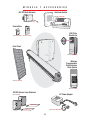
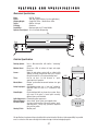
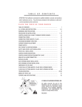
1
Click on the desired topic in the “Bookmarks” column or “Table of Contents” to select page.
T A B L E
O F
C O N T E N T S
Attention: This handbook is exclusively for qualified installation personal, and assistance and/or maintenance
service. - The performances indicated in this handbook are valid only if a correct assembly has been carried out.
UL Listings and Instructions
Warnings and Precautions
“Open to the Inside” Mounting Specifications
“Open to the Outside” Mounting Specifications
Step-by-Step Operator Mounting Instructions
Removing the Control Board
Mounting the Control Box
Wiring 1 Operator to the Control Board
Wiring 2 Operators (Master/Slave) to the Control Board
Choosing Gate Movement Direction
Sensor Adjustment
Connecting Power Supply
Wiring Additional Inputs
Safety and Center Loop Installation
Photocell Installation
Single Control Board Description
Master / Slave Control Board Description
Alarm / Maglock Control Board Connections
UL Audio Alarm
Burglar Alarm
“Gate Opening Inside” Installation of Maglock / Solenoid
“Gate Opening Outside” Installation of Maglock / Solenoid
Emergency Key Release
Close Delay Option
Troubleshooting
Optional Solar Power
Miracle 1 Parts Illustration
Miracle 1 Parts List / Maintenance
Miracle 1 Accessories
Features and Specifications
2-5
6
7
8
9-12
13
13
14
15
16
16
17
18
19
20
21
22
23
24
24
25
26
27
28-29
30-32
33
34
35
36
37
Please DO NOT
Touch me!...
Unless you are an
Authorized Service
Technician!
© 1998 BY ELITE ACCESS SYSTEMS, INC.
All rights reserved. No part of this manual may be reproduced in
any means without the expressed written permission of the
publisher. Materials, components and specifications are subject to
change without notice.
Release 2
5/02
1
U L
L I S T I N G S
A N D
I N S T R U C T I O N S
Installation Instructions Regarding the Gate Operator
A) Install the gate operator only when:
1. The operator is appropriate for the construction and the usage Class of the gate.
2. All openings of a horizontal slide gate are guarded or screened from the bottom of the
gate to a minimum of 4 feet (1.2 m) above the ground to prevent a 2 1/4inch (57.15 mm)
diameter sphere from passing through the openings anywhere in the gate, and in that
portion of the adjacent fence that the gate covers in the open position.
3. All exposed pinch points are eliminated or guarded, and
4. Guarding is supplied for exposed rollers.
B) The operator is intended for installation only on gates used for vehicles. Pedestrians must be
supplied with a separate access opening.
C) The gate must be installed in a location so that enough clearance is supplied between the gate
and adjacent structures when opening and closing to reduce the risk of entrapment. Swinging
gates shall not open into public access areas.
D) The gate must be properly installed and work freely in both directions prior to the installation of
the gate operator.
E) Controls must be far enough from the gate so that the user is prevented from coming in contact
with the gate while operating the controls. Controls intended to be used to reset an operator after
2 sequential activations of the entrapment protection device or devices must be located in the line
of sight of the gate outdoor or easily accessible controls shall have a security feature to prevent
unauthorized use.
F) All warning signs and placards must be installed where visible in the area of the gate.
2
U L
L I S T I N G S
A N D
I N S T R U C T I O N S
G) For a gate operator utilizing a non-contact sensor such as a photo beam:
1. See instructions on the placement of non-contact sensor for each Type of application.
2. Care shall be exercised to reduce the risk of nuisance tripping, such as when a vehicle
trips the sensor while the gate still moving.
3. One or more non-contact sensors shall be located where the risk of entrapment or
obstruction exists, such as the perimeter reachable by a moving gate or barrier.
H) For a gate operator utilizing a contact sensor such as an edge sensor:
1. One or more contact sensors shall be located at the leading edge, trailing edge and post
mounted both inside and outside of a vehicular horizontal slide gate.
2. One or more contact sensors shall be located at the bottom edge of a vehicular vertical
lift gate.
3. One or more contact sensors shall be located at the pinch point of a vehicular vertical
pivot gate.
4. A hard wired contact sensor shall be located and its wiring arranged so that the
communication between the sensor and the gate operator is not subjected to mechanical
damage.
5. A wireless contact sensor such as the one that transmits radio frequency (RF) signals to
the gate operator for entrapment protection functions shall be located where the
transmission of the signals are not obstructed or impeded by building structures, natural
landscaping or similar obstruction. A wireless contact sensor shall function under the
intended end-use conditions.
3
U L
L I S T I N G S
A N D
I N S T R U C T I O N S
Important Safety Instructions
Warning - To reduce the risk of injury or death:
1. READ AND FOLLOW ALL INSTRUCTIONS.
2. Never let children operate or play with gate controls. Keep the remote control away from
children.
3. Always keep people and objects away from the gate while the gate is in operation.
NO ONE SHOULD CROSS THE PATH OF A MOVING GATE!
4. Test the gate operator monthly. The gate MUST reverse on contact with a rigid object or
stop when an object activates the non-contact sensors. After adjusting the force or the
limit of travel, retest the gate operator, Failure to adjust and retest the gate operator
properly can increase the risk of injury or death.
5. Use the emergency release only when the gate is not moving. Make sure the power for
the gate operator is off.
6. KEEP GATES PROPERLY MAINTAINED. Read the manual. Have a qualified service
person make repairs to the gate or gate hardware.
7. The entrance is for vehicles only. Pedestrians must use separate entrance.
8. SAVE THESE INSTRUCTIONS.
4
U L
L I S T I N G S
A N D
I N S T R U C T I O N S
Gate – A moving barrier such as a swinging, sliding, raising lowering, rolling, or like, barrier,
that is a stand-alone passage barrier or is that portion of a wall or fence system that controls
entrance and/or egress by persons or vehicles and completes the perimeter of a defined
area.
Vehicular horizontal slide-gate operator (or system) – A vehicular gate operator (or
system) that controls a gate which slides in a horizontal direction that is intended for use for
vehicular entrance or exit to a drive, parking lot, or the like.
Residential vehicular gate operator – Class I – A vehicular gate
operator (or system) intended for use in a home of one-to four
single family dwelling, or a garage or parking area associated
therewith.
Commercial/General access vehicular gate operator –
Class II – A vehicular gate operator (or system) intended for
use in a commercial location or building such as a multifamily housing unit (five or more single family units) hotel,
garages, retail store or other building servicing the general
public.
Commercial/General access vehicular gate operator –
Class III – A vehicular gate operator (or system) intended for
use in a industrial location or building such as a factory or
loading dock area or other locations not intended to service
the general public.
Restricted access vehicular gate operator – Class IV – A
vehicular gate operator (or system) intended for use in a
guarded industrial location or building such as an airport
security area or other restricted access locations not
servicing the general public, in which unauthorized access is
prevented via supervision by security personnel.
5
W A R N I N G S
A N D
P R E C A U T I O N S
Warning - To reduce the risk of injury to persons,
The Miracle-1 is for Vehicular Gate use ONLY!
Be sure to read and follow all these important instructions before installation of the gate operator. Elite
Access Systems, Inc. is not responsible for improper installation or failure to comply with local building and
electrical codes.
DO NOT install upside down.
DO NOT install on a few pickets, they will bend.
Weld a reinforcement bar across entire gate.
DO NOT install on ANY pedestrian passageways or
DO NOT install on ANY pedestrian gates.
doorways.
DO NOT install on uphill or downhill gates.
DO NOT install next to
sprinklers or any area that
may expose bottom of
operator to water.
DO NOT over-bend the
cord from the operator.
Doing this will cause the
wires to eventually break.
Caution - If the “Timer” is to be left in the “ON” position, then add a safety loop and center loop.
IMPORTANT SAFETY INSTRUCTIONS
WARNING - To reduce the risk of severe injury or death:
1. READ AND FOLLOW ALL INSTRUCTIONS.
2. Never let children operate or play with gate controls. Keep the remote control away from children.
3. Always keep the moving gate in sight and away from people and objects until it is completely closed.
NO ONE SHOULD CROSS THE PATH OF THE MOVING GATE.
4. KEEP GATES PROPERLY MAINTAINED. Read the owner’s manual. Have a qualified service person periodically inspect and
make repairs to gate hardware.
5. SAVE THESE INSTRUCTIONS.
6
P R O C E D U R E
O p e n
F O R
T o
I N S T A L L A T I O N
T h e
I n s i d e
Important:
Weld Re-Bar
Behind Gate
Hinges for
Maximum
Strength
Gate Hinge
Gate Hinge
Steel Re-Bar
Heavy Steel Plates for
Reinforcement
(Not Supplied)
10"
Minimum
Back Steel Bracket
(Reinforce if necessary)
Heavy Steel
Plates for
Reinforcement
(Not Supplied)
Back Steel Bracket
(Reinforce if
necessary)
Heavy
Steel Top View
Plate Post Setup
Gate Hinge
Typical Masonry Column Setup
Typical Steel
Post Setup
25.75"
8.5"
Gate Hinge
Out
Gate in Closed Position
In
6"
7.75"
Miracle 1 in Closed Position
90° / 105°
Miracle 1 in
6"
Indexing on
mounting hole in
the front steel
bracket.
Gate in Open Position
Open Position
Indexing on central hole in
the back steel bracket.
10.25"
7
P R O C E D U R E
O p e n
F O R
T o
T h e
I N S T A L L A T I O N
O u t s i d e
Important:
Weld Re-Bar
Behind Gate
Hinges for
Maximum
Strength
Gate Hinge
Gate Hinge
Heavy Steel Plate for
Reinforcement
(Not Supplied)
Steel Re-Bar
Heavy Steel Plates
for Reinforcement
(Not Supplied)
Back Steel Bracket
(Reinforce if necessary)
Back Steel
Bracket
(Reinforce
if necessary)
Gate Hinge
Typical Masonry
Column Setup
Typical Steel
Post Setup
Indexing on
mounting hole in
the front steel
bracket.
6"
6"
Indexing on central hole in
the back steel bracket.
Miracle 1 in Open Position
Gate in Open Position
Gate Hinge
Heavy Steel Top View
Plate
Post Setup
90° / 105°
Out
Gate in Closed Position
In
8.5"
This Plate
Not Supplied
Miracle 1 in
7.75"
25.75"
8
n
Closed Positio
P R O C E D U R E
F O R
M o u n t i n g
I N S T A L L A T I O N
I n s t r u c t i o n s
Step 1: Remove the 4 screws and lift the
operator cover off.
Step 2: Release the mechanical lock by turning the
key to the horizontal position.
Step 3: Position the Miracle 1 horizontally level on the closed gate, where desired. For strength purposes, the
front steel bracket must be attached in an area that can withstand heavy forces. Additional reinforcement steel
plates may be necessary for mounting.
If using a gate crossbar, weld bar across all pickets. Do not weld
the crossbar on a few pickets, or they will bend.
The Miracle 1 can be mounted on top
of the gate frame.
Step 4: Position and level the operator brackets and reinforcement plates. (See next page). Tack weld brackets
and plates in position.
Important:
Tack weld the front steel
bracket at the top of the
crossbar, so the operator
will not hit the crossbar
when in motion.
9
P R O C E D U R E
F O R
M o u n t i n g
I N S T A L L A T I O N
I n s t r u c t i o n s
Step 4 (con't):
The gate must be in the closed position. Make sure the operator is kept level while tack
welding the front and back steel brackets and reinforcement steel plates in position. After all tack welding is
finished, remove the operator!
Refer to Step 6
2.25" Vertical Height Difference
Refer to Step 7
Step 5: With the operator removed, completely weld around the brackets and plates on the gate.
Caution: Welding the brackets with the operator attached to the gate may damage the operator.
Step 6: Remove the nut, bolt and bushing from
the back operator bracket. Place the metal bushing
in the hole of the steel bracket that will be used.
Secure operator with the nut and bolt (See Below).
Step 7: Remove the nut from the traveler carriage at
the front of the operator. Secure operator to the front
bracket with the washer and nut (See Below).
Important:
Metal
Bushing
Back
Bracket
Washer Must be
placed between
traveler carriage
and front bracket.
Important:
These nuts MUST be tight.
10
Traveler
Carriage
Front Bracket
P R O C E D U R E
F O R
M o u n t i n g
I N S T A L L A T I O N
I n s t r u c t i o n s
Step 8:
Make sure that the operator is level or it will not function properly. An off-level installation may
cause the gate or operator to fail prematurely.
Step 9: Lock the operator by turning the
key to the vertical position while pushing
or pulling on the gate until you hear the
key release click into place. the gate
should not move after the operator has
been locked. Completing this successfully
finishes the basic mounting of the
operator to the gate. The next steps are to
make all electrical connections to the
operator and control board.
ull
P
Push or
Click!
Step 10: The following pages show the correct electrical procedures needed for the operator. After completing
all the electrical connections, continue to step 11 to complete the final adjustments on the operator.
11
P R O C E D U R E
A d j u s t i n g
F O R
t h e
I N S T A L L A T I O N
L i m i t
S w i t c h e s
Step 11:
Adjust the travel distance of the gate with the limit switches. Loosen the 2 bolts of each limit switch
armature. Slide to adjust. Position the outside limit switches of each armature to stop the gate in the “full open”
and “full closed” positions. Re-tighten armature bolts when gate positions are correct.
Outside Limit
Switch
Inside Limit
Switch
Limit Switch
Armature
Adjustment Bolts
Inside Limit Switch
Outside Limit Switch
Adjustment Bolts
Limit Switch Armature
Step 12: Reinstall the operator cover with the 4 screws to complete
the installation.
12
R E M O V I N G
T H E
C O N T R O L
B O A R D
Unscrew the 4 Phillips head screws from the plastic cover and remove.
MAGLOCK
ALARM
SYSTEM
ON
REVERSE
SENSOR
MAGLOCK
ALARM
SENSOR
ALARM
SENSOR
POWER
CHARGE OK
BAT
CENTRAL
LOW
CONTROL
2A 250V
TIMER
OFF
3
OPEN
OUTSIDE
OPEN
INSIDE
1.5A 250V
60
REVERSE
SENSOR
REPLACE FUSE
WHEN LED IS ON
YES
ON
ALARM
SYSTEM
ON
OPEN
OUTSIDE
NO
WARNING: FOR CONTINUED
PROTECTION AGAINST FIRE
REPLACE ONLY WITH SAME
TYPE & VOLTAGE FUSE
OPEN
INSIDE
STOP BY
POSITIVE
STOP
STOP BY
POSITIVE
STOP
ON
60
TIMER
8A 125V
POWER
BATTERY LOW
CENTRAL
ACCESS SYSTEMS INC
MADE IN USA
CONTROL
CENTER
STRIKE SAFETY RADIO LOOP
REC
OPEN LOOP
®
ACCESS SYSTEMS INC
8
8
3
CHARGE OK
STRIKE SAFETY RADIO CENTER
OPEN
LOOP
REC
LOOP
WARNING: FOR CONTINUED PROTECTION
AGAINST FIRE REPLACE ONLY WITH
SAME TYPE & VOLTAGE FUSE
REPLACE FUSE
WHEN LED IS ON
YES
NO
OFF
Remove the three Phillips head screws. Remove control
board. Reverse this process to reinstall the control board.
Detach the J1 and J3 plug.
M O U N T I N G
T H E
C O N T R O L
B O X
Caution: Do Not make new mounting holes, or enlarge existing holes in control box. Use
the four mounting holes provided.
Remove the four nuts and remove battery rack.
Reverse this process to reinstall.
Mount control box with four screws and washers
(recommend #10 thru 1/4-20 Bolts or Screws)
Do Not over tighten.
13
WIRING
1
OPERATOR
TO
CONTROL
BOARD
Caution: Do Not over-bend the cord from the operator.
Doing this will cause the wires to eventually break.
Wire Gauge:
16 AWG / 200 Ft.
J1 Plug
10
8
6
4
2
9
7
5
3
1
ck
Bla
d
Re
To Battery
24 VDC
MAGLOCK
ALARM
SYSTEM
ON
k
REVERSE
SENSOR
c
Bla
ALARM
SENSOR
OPEN
OUTSIDE
NO
60
wn
OFF
3
POWER
CHARGE OK
BAT
CENTRAL
e
LOW
CONTROL
STRIKE SAFETY RADIO CENTER
OPEN
LOOP
REC
LOOP
en
Gre
8A
8 125V
Blu
WARNING: FOR CONTINUED PROTECTION
AGAINST FIRE REPLACE ONLY WITH
SAME TYPE & VOLTAGE FUSE
Bro
REPLACE FUSE
WHEN LED IS ON
YES
ON
TIMER
2A 250V
d
Re
1.5A 250V
OPEN
INSIDE
STOP BY
POSITIVE
STOP
WARNING: FOR CONTINUED
PROTECTION AGAINST FIRE
REPLACE ONLY WITH SAME
TYPE & VOLTAGE FUSE
ite
Wh
ACCESS SYSTEMS INC
MADE IN USA
Important:
Be sure to install the Flex Connector
(supplied) to secure the wire in the
Miracle 1 Control Board Box.
Conduit and flex
connector secured to
control box.
14
W I R I N G
2
O P E R AT O R S
Field
Wiring
Box
M A S T E R
/
S L AV E
6 Wires from Operator in Conduit
Wire Gauge:
16 AWG / 200 Ft.
Operator 1 (Master)
Operator 2 (Slave)
Caution: Do Not over-bend
the cord from the operator.
Doing this will cause the
wires to eventually break.
MASTER
MAGLOCK
SLAVE
SYSTEM ON
ALARM
REVERSE
SENSOR
ALARM
SENSOR
J1 Plug
OPEN OUT
OPEN IN
OFF
POS STOP
ON
POS STOP
CLOSE DLY
ON
CLOSE DLY
OFF
OFF
60
ON
3
TIMER
16 14 12 10
8
6
4
2
POWER
CHARGE OK
BATTTERY LOW
15 13 11 9
7
5
3
1
3A 250V
1.5A 250V
CONTROL
WARNING: FOR CONTINUED
PROTECTION AGAINST FIRE
REPLACE ONLY WITH SAME
TYPE & VOLTAGE FUSE
15A 250V
WARNING: FOR CONTINUED PROTECTION
AGAINST FIRE REPLACE ONLY WITH
SAME TYPE & VOLTAGE FUSE
REPLACE FUSE
WHEN LED IS ON
CENTRAL
STRIKE SAFETY RADIO CENTER
OPEN
LOOP
REC
LOOP
ck
Bla
d
Re
To Battery
24 VDC
ck
Bla
ite
Wh
d
Re
wn
Bro
Slave
e
Blu
en
Gre
Gre
en
Blu
e
Bro
wn
Re
d
Wh
ite
Bla
ck
Conduit and flex
connector secured to
control box.
Important:
Master
Be sure to install the Flex Connector
(supplied) to secure the wire in the
Miracle 1 Control Board Box.
15
C H O O S I N G
G AT E
M O V E M E N T
D I R E C T I O N
Switch the “Open Inside / Open Outside” switch on the control board
to the corresponding position for the proper direction.
MAGLOCK
ALARM
SYSTEM
ON
REVERSE
SENSOR
ALARM
SENSOR
OPEN
OUTSIDE
REPLACE FUSE
WHEN LED IS ON
YES
60
OFF
3
POWER
CHARGE OK
BAT
CENTRAL
LOW
CONTROL
2A 250V
ON
1.5A 250V
NO
TIMER
WARNING: FOR CONTINUED
PROTECTION AGAINST FIRE
REPLACE ONLY WITH SAME
TYPE & VOLTAGE FUSE
OPEN
INSIDE
STOP BY
POSITIVE
STOP
8A 125V
WARNING: FOR CONTINUED PROTECTION
AGAINST FIRE REPLACE ONLY WITH
SAME TYPE & VOLTAGE FUSE
STRIKE SAFETY RADIO CENTER
OPEN
LOOP
REC
LOOP
ACCESS SYSTEMS INC
MADE IN USA
The gate opens outward.
The gate opens inward.
S E N S O R
A D J U S T M E N T
Caution: The sensors must be adjusted while the gate is in the opening or closing cycle.
MAGLOCK
ALARM
SYSTEM
ON
Adjusted by Qualified
Service Personnel
REVERSE
SENSOR
ALARM
SENSOR
OPEN
OUTSIDE
REPLACE FUSE
WHEN LED IS ON
YES
60
TIMER
OFF
3
POWER
CHARGE OK
BAT
CENTRAL
LOW
2A 250V
ON
CONTROL
1.5A 250V
NO
WARNING: FOR CONTINUED
PROTECTION AGAINST FIRE
REPLACE ONLY WITH SAME
TYPE & VOLTAGE FUSE
OPEN
INSIDE
STOP BY
POSITIVE
STOP
8 125V
8A
Minimum
Sensitivity
WARNING: FOR CONTINUED PROTECTION
AGAINST FIRE REPLACE ONLY WITH
SAME TYPE & VOLTAGE FUSE
STRIKE SAFETY RADIO CENTER
OPEN
LOOP
REC
LOOP
ACCESS SYSTEMS INC
MADE IN USA
Maximum Sensitivity
Set the sensor adjustment so when the gate hits any object while opening,
it will stop and when the gate hits any object while closing, it will reverse.
Note: If you activate the operator and the gate stops in the middle of the
driveway, the sensor is set too sensitive.
Option –
Stop by Positive - Stop
This option is to be turned to
“yes” if the gate will use
positive stops at the close
position.
Important: It is necessary to still adjust your limit switch at the close position.
The controller will look for the limit close first and then it will look for the positive stop.
16
C O N N E C T I N G
P O W E R
S U P P L Y
Connect the two yellow wires from the J3 plug connector to low voltage, direct burial landscape lighting cable, 14
gauge/300 watt not exceeding 500 ft, 10 AWG up to 1000 ft. Connect the lighting cables into Elite's plug-in
transformer 24 VAC (Included). Polarity does not matter. The transformer needs 115 VAC.
To
115
VAC
24 VAC Plug-in Transformer
40 VA
J3 Plug
16 15 14 13 12
11 10 9 8
7 6
14 Gauge Wires
5 4 3
2 1
Control
Board
J3 Plug
Connector
Polarity does not matter
Yellow Wires
#1, #2
Caution: The maximum length of wire should not exceed 500 ft.
If using more than 500 ft, use 10 AWG wire up to 1000 ft.
After the transformer has been plugged into the power source, connect the battery cable plug
into the motor harness connector from the J1 plug. The “Timer” LED will flash “3 times”.
MAGLOCK
ALARM
Motor Harness Connector
from the J1 Plug
SYSTEM
ON
REVERSE
SENSOR
ALARM
SENSOR
OPEN
OUTSIDE
NO
REPLACE FUSE
WHEN LED IS ON
YES
ON
60
TIMER
OFF
3
POWER
CHARGE OK
BAT
CENTRAL
Battery
Cable Plug
LOW
CONTROL
1.5A 250V
STOP BY
POSITIVE
STOP
2A 250V
OPEN
INSIDE
WARNING: FOR CONTINUED
PROTECTION AGAINST FIRE
REPLACE ONLY WITH SAME
TYPE & VOLTAGE FUSE
Blink!
Blink!
Blink!
8A 125V
WARNING: FOR CONTINUED PROTECTION
AGAINST FIRE REPLACE ONLY WITH
SAME TYPE & VOLTAGE FUSE
STRIKE SAFETY RADIO CENTER
OPEN
LOOP
REC
LOOP
ACCESS SYSTEMS INC
MADE IN USA
After that, check the “Charge OK” LED......
......it must be “ON”.
TIMER
OFF
3
POWER
BAT
CENTRAL
LOW
CONTROL
1.5A 250V
60
2A 250V
ON
WARNING: FOR CONTINUED
PROTECTION AGAINST FIRE
REPLACE ONLY WITH SAME
TYPE & VOLTAGE FUSE
REPLACE FUSE
WHEN LED IS ON
If you see these LED's “ON”, replace fuse.
17
W I R I N G
A D D I T I O N A L
I N P U T S
Important:
Wiring at 7 and 12 will be recognized as an Open Only
command, and Will Not close the gate. To Close the
gate with this wiring configuration, the control board
timer must be turned ON. If the timer is not turned on,
the gate will remain open. To provide close command
use 4 and 5.
Wiring at 4 and 5 will be recognized as a
Three Push Button command. The First
command will open the gate. The
Second command will
stop the gate. The Third
16 15 14 13
command will close the
12 11 10 9 8
gate.
J3 Plug
7
6
5 4
3 2 1
Control Board
J3 Plug
Connector
Input for 3 push button control
Pin 7 and 12 for Open Only command
Key Switch
1
HELP
2
3
4
5
6
7
8
9
0
Card Reader
Push Button
Digital Lock
Card Reader
Exit Loop
Detector
Elite Entry Phone
Mount receiver inside the control board
box as shown using velcro. Note that the
receiver is mounted upside down so the
antenna can fit through the hole at the
bottom of the control board box.
J3 Plug
Connector
32
1
16 15 14 13 12
11 10 9 8 7
6
1 (24V) / Ground
black
2 (Relay)
white
3 (Radio Power) / +24V
red
18
5 4 3
2 1
Digital Lock
SAFETY
AND
CENTER
LOOP
INSTALLATION
OUT
15'
4'
4'
Safe
Loop ty
4'
4'
Cen
Loo ter
p
Center Loop Even
with Open End
of Gate
4'
4'
Twisted
Wires
4' Safe
Loo ty
p
4'
7'
IN
From Loop
Cuts
Center Loop
BLUE
1 1/2"
Fill Loop Cuts
with Proper Sealer
YELLOW
J3 Plug
Connector
16 15 14 13
12 11
10 9
BLUE
1/4"
Use 14 AWG "uf" Grade
Stranded Wire
8
7
6
5 4 3 2
1
YELLOW
Safety Loop
Important:
Be sure to twist
wires together.
To Loop
Detector
Loop Cut
Three
Wire
Layers
Important:
If the gate is closing and receives a safety loop command, the gate WILL NOT reopen.
It will stop and resume closing, once the car clears the loop.
19
Loop
Cut
1/4"
Wide
P H O T O C E L L
I N S T A L L A T I O N
Gate in Closed Position
To reduce the risk of injury, You must install a photocell sensor when the gate opens to less than 18”
from a wall or any other object or potential entrapment installation. Follow the installation instructions
provided with the photocell sensor for accurate placement of the photocell and the reflector.
Potential Entrapment
Area (Shaded)
Photocell
Reflector
and
Bracket
Gate in Open Position
Less than 18"
If multiple sensors are being used, all of the photo beam sensors
are to be connected in parallel at the sensor input on the control
board.
MAGLOCK
If you are going to use a non-contact sensor as a secondary
entrapment protection you should use a recognized component to
component to comply with the revised UL 325 intended to be used
in class I or class II gate operator, like the following: OMRON
Retro-Reflective Photocell, Model: E3K-R10K4-NR
ALARM
SYSTEM
ON
REVERSE
SENSOR
ALARM
SENSOR
16 15 14 13
(C1) (NO1)
3
4
5
24V to
6 240VDC
12 11 10
Black 22 AWG
Red 22 AWG
Black 16 AWG
Black 16 AWG
20
LOW
CONTROL
2A 250V
BAT
CENTRAL
8A 125V
WARNING: FOR CONTINUED PROTECTION
AGAINST FIRE REPLACE ONLY WITH
SAME TYPE & VOLTAGE FUSE
STRIKE SAFETY RADIO CENTER
OPEN
LOOP
REC
LOOP
ACCESS SYSTEMS INC
MADE IN USA
J3 Plug
J3 Plug
Connector
1 2
POWER
CHARGE OK
8
DARK ON
OFF
3
1.5A 250V
60
Important!
LIGHT ON
REPLACE FUSE
WHEN LED IS ON
YES
ON
Elite Part # A OMRON
This switch must be in the
"Light On" position or
photocell will not function
correctly.
OPEN
OUTSIDE
NO
TIMER
WARNING: FOR CONTINUED
PROTECTION AGAINST FIRE
REPLACE ONLY WITH SAME
TYPE & VOLTAGE FUSE
OPEN
INSIDE
STOP BY
POSITIVE
STOP
9 8 7 6
5
4
3
2 1
C O N T R O L
28
B O A R D
27
D E S C R I P T I O N
26
25
24 23 22 21 20 19 18
1
17
2
16
15
14
1
13
12
11
8
10
9
3
4
5
6
7
8
1 Open or Close Relay LED
15 Board Fuse
2 Control Relay LED
16 Replace Charging Power Fuse LED
3 Motor Fuse
17 Replace Board Power Fuse LED
4 J1-Batteries and Motor Connector
18 Timer Pot (3 to 60 sec.)
5 Strike Open LED
19 Timer Active LED
6 Safety Loop LED
20 Switch-Timer On / Off
7 Radio Receiver LED
21 Stop by Positive Stop Option Switch
8 Center Loop LED
22 Switch-Open Inside / Outside
9 J3 Transformer & Input Commands Connector
23 Reverse Sensor Adjustment
10 Central Control LED
24 Alarm Sensor LED
11 Batteries Low LED
25 System On LED
12 Charger Ok LED
26 Reverse Sensor LED
13 Power LED
27 Burglar Alarm & Audio Alarm Output Connector
14 Charging Power Fuse
28 Maglock Connector
21
CONTROL
BOARD
DESCRIPTION
29
Master
/
27
28
1
Slave
26
25
24
23
22
21
20
19
2
18
1
17
16
15
14
13
12
11
10
3
4
5
6
7
8
9
1 Open or Close Relay LED
15 Board Fuse
2 Control Relay LED
16 Replace Charging Power Fuse LED
3 Motor Fuse
17 Replace Board Power Fuse LED
4 J1-Batteries and Motor Connector
18 Timer Active LED
5 Strike Open LED
19 Timer Pot (3 to 60 sec.)
6 Safety Loop LED
20 Switch-Timer On / Off
7 Radio Receiver LED
21 Overlapping Gate On / Off
8 Center Loop LED
22 Stop by Positive Stop Option Switch
9 J3 Transformer & Input Commands Connector
23 Switch-Open Inside / Outside
10 Central Control LED
24 Alarm Sensor LED
11 Batteries Low LED
12 Charger Ok LED
25 Reverse Sensor Adjustment
26 Reverse Sensor LED
13 Power LED
14 Charging Power Fuse
27 System On LED
28 Burglar Alarm & Audio Alarm Output Connector
29 Maglock Connector
22
A L A R M
&
M A G L O C K
C O N N E C T I O N S
Relay Contact Rating
0.5 A - 125 VAC
1 A - 24 VDC
Use the harness provided with the unit to make your connections to these alarm outputs.
Maglock Connection
Alarm Connection
UL Audio Alarm
Connection
1 2 3
1 2 3 4
2
1
1 or 3
2 Orange Wires
2
3
4
Connect for Open Inside
1. Power - for Open Inside
2. Ground
Burglar Alarm
Relay Output
1. Common
2. N. O.
OR
Connect for Open Outside
2. Ground
3. Power - for Open Outside
23
UL Audio Alarm Connection
3 and 4 UL Audio Alarm
U L
A U D I O
A L A R M
This UL alarm is required per UL-325. It will go off after 2 consecutive events on reverse sensor.
The UL alarm will sound for a period of 5 minutes or until a new command is received by one of the commands in
column A but NOT column B.
1 2 3 4
B
Strike Open
J3 - 7 & 12
Safety Loop
J3 - 6 & 12
UL Audio Alarm
B U R G L A R
The control board provides a relay with a
normally open contact to interface with a
house alarm.
T
wi hes
ala ll N e i
rm OT npu
! re ts
se
t
A
UL Alarm Plug
Connector
Center Loop
J3 - 8 & 12
Radio Receiver
J3 - 4 & 5
A L A R M
COM
1
Burglar Alarm
Plug Connector
Relay Contact Rating
2
N.O.
0.5 A - 125 VAC
1 A - 24 VDC
1 2 3 4
Use the harness provided
with the unit to make your
connections to these alarm
outputs.
COM
N.O.
Important:
When interfacing with a house burglar alarm you must install positive stops at the gate closed position.
Proximity Switch
If the gate is forced open without a
valid command, the proximity switch
will be activated, causing the house
alarm to activate.
2"
Max.
16 15 14 13
12 11 10
9 8 7 6
5 4 3 2 1
J3 Plug Connector
Two Wires (N.O. and COM.)
From Proximity Switch
Elite Part # A PRS
24
G AT E O P E N I N G “ I N S I D E ” I N S TA L L AT I O N O F. . .
MAGLOCK
ALARM
SYSTEM
ON
REVERSE
SENSOR
ALARM
SENSOR
OPEN
OUTSIDE
REPLACE FUSE
WHEN LED IS ON
YES
ON
60
OFF
3
TIMER
POWER
CHARGE OK
BAT
CENTRAL
LOW
CONTROL
1.5A 250V
NO
2A 250V
STOP BY
POSITIVE
STOP
WARNING: FOR CONTINUED
PROTECTION AGAINST FIRE
REPLACE ONLY WITH SAME
TYPE & VOLTAGE FUSE
OPEN
INSIDE
3
8A 125V
1 2
WARNING: FOR CONTINUED PROTECTION
AGAINST FIRE REPLACE ONLY WITH
SAME TYPE & VOLTAGE FUSE
STRIKE SAFETY RADIO CENTER
OPEN
LOOP
REC
LOOP
ACCESS SYSTEMS INC
MADE IN USA
Control Board
1. Power - Plug in orange wire to open gate Inside
2. Ground - Always plugged in
...Solenoid
Lock Wiring
Orange
Wires
Yellow Wire (N.O.)
Elite Part # A PRS
White Wire (Common)
Power
for
Solenoid
Contact Rating
125 VAC - 0.5 A
Custom Bracket
Magnetic Lock Plate
Magnetic Lock
Gate
Yellow - Normally Open (N.O.)
White - Common
Blue - Normally Closed (N.C.)
Fence
...Magnetic Lock Wiring
Note:
The optional relay harness, allowing
interface with external devices, is
available, only from Elite Access
Systems
Blue Wire (N.C.)
White Wire (Common)
25
Power
for
Maglock
G AT E O P E N I N G “ O U T S I D E ” I N S TA L L AT I O N O F. . .
MAGLOCK
ALARM
SYSTEM
ON
REVERSE
SENSOR
ALARM
SENSOR
OPEN
OUTSIDE
REPLACE FUSE
WHEN LED IS ON
YES
ON
60
TIMER
OFF
3
POWER
CHARGE OK
BAT
CENTRAL
LOW
CONTROL
1.5A 250V
NO
2A 250V
STOP BY
POSITIVE
STOP
WARNING: FOR CONTINUED
PROTECTION AGAINST FIRE
REPLACE ONLY WITH SAME
TYPE & VOLTAGE FUSE
OPEN
INSIDE
23
8A 125V
1
WARNING: FOR CONTINUED PROTECTION
AGAINST FIRE REPLACE ONLY WITH
SAME TYPE & VOLTAGE FUSE
STRIKE SAFETY RADIO CENTER
OPEN
LOOP
REC
LOOP
ACCESS SYSTEMS INC
MADE IN USA
2. Ground - Always plugged in
3. Power - Plug in orange wire to open gate Outside
Control Board
...Solenoid Lock Wiring
Orange
Wires
Elite Part # A PRS
Yellow Wire (N.O.)
White Wire (Common)
Contact Rating
125 VAC - 0.5 A
Power
for
Solenoid
Yellow - Normally Open (N.O.)
White - Common
Blue - Normally Closed (N.C.)
...Magnetic Lock Wiring
Note:
The optional relay harness, allowing
interface with external devices, is
available, only from Elite Access
Systems
Blue Wire (N.C.)
White Wire (Common)
26
Power
for
Maglock
E M E R G E N C Y
K E Y
R E L E A S E
Step 1:
To move the gate during an emergency or
power failure, insert key and turn counterclockwise to
Unlock the Miracle 1 from the gate.
Unlock
Key Provided
Step 2: Move the gate manually to the full open position 90°.
Full Open Position
90 Degrees
Step 3: Re-Lock the operator by turning the key
clockwise while pushing or pulling on the gate until
you hear the key release click into place. The operator
can resume normal operation as soon as power is
restored.
ull
P
Push or
Lock
Click!
27
C L O S E
D E L A Y
M a s t e r / S l a v e
O P T I O N
O n l y
This option is to be used when there is a master/slave installation with overlapping gates.
MASTER
MAGLOCK
SLAVE
SYSTEM ON
ALARM
REVERSE
SENSOR
ALARM
SENSOR
OPEN OUT
OPEN IN
OFF
POS STOP
ON
POS STOP
CLOSE DLY
ON
CLOSE DLY
OFF
OFF
60
ON
3
TIMER
POWER
CHARGE OK
BATTTERY LOW
1.5A 250V
STRIKE SAFETY RADIO CENTER
OPEN
LOOP
REC
LOOP
3A 250V
CONTROL
WARNING: FOR CONTINUED
PROTECTION AGAINST FIRE
REPLACE ONLY WITH SAME
TYPE & VOLTAGE FUSE
15A 250V
WARNING: FOR CONTINUED PROTECTION
AGAINST FIRE REPLACE ONLY WITH
SAME TYPE & VOLTAGE FUSE
REPLACE FUSE
WHEN LED IS ON
CENTRAL
Opening “Inside” and Overlap to the “Outside”...
Slave
Master
Inside Property
Master operator delays to close the gate.
Opening “Inside” and Overlap to the “Inside”...
Slave
Master
Inside Property
Master operator delays to close the gate.
28
C L O S E
D E L A Y
O P T I O N
M a s t e r / S l a v e
O n l y
This option is to be used when there is a master/slave installation with overlapping gates.
MASTER
MAGLOCK
SLAVE
SYSTEM ON
ALARM
REVERSE
SENSOR
ALARM
SENSOR
OPEN OUT
OPEN IN
OFF
POS STOP
ON
POS STOP
CLOSE DLY
ON
CLOSE DLY
OFF
OFF
60
ON
3
TIMER
POWER
CHARGE OK
BATTTERY LOW
1.5A 250V
STRIKE SAFETY RADIO CENTER
OPEN
LOOP
REC
LOOP
3A 250V
CONTROL
WARNING: FOR CONTINUED
PROTECTION AGAINST FIRE
REPLACE ONLY WITH SAME
TYPE & VOLTAGE FUSE
15A 250V
WARNING: FOR CONTINUED PROTECTION
AGAINST FIRE REPLACE ONLY WITH
SAME TYPE & VOLTAGE FUSE
REPLACE FUSE
WHEN LED IS ON
CENTRAL
Opening “Outside” and Overlap to the “Outside”...
Master operator delays to close the gate.
Mas
ter
Slave
Inside Property
Opening “Outside” and Overlap to the “Inside”...
Master operator delays to close the gate.
Mas
ter
Slave
Inside Property
29
T R O U B L E S H O O T I N G
Check the Fuses
If the gate is not moving in any direction be sure to check all of the LED displays on the control board. If the board
power or charging power LEDs are on, change the corresponding fuse on the right side of the board. If the motor
will not work, and all LED's on the board are ok, check the fuse on the left side of the board and replace if
necessary.
Master / Slave
MASTER
MAGLOCK
SLAVE
SYSTEM ON
ALARM
REVERSE
SENSOR
ALARM
SENSOR
OPEN OUT
OPEN IN
OFF
POS STOP
ON
POS STOP
CLOSE DLY
ON
CLOSE DLY
OFF
OFF
60
ON
3
TIMER
Change Fuse
POWER
CHARGE OK
3A 250V
STRIKE SAFETY RADIO CENTER
OPEN
LOOP
REC
LOOP
1.5A 250V
1.5A 250V
CONTROL
WARNING: FOR CONTINUED
PROTECTION AGAINST FIRE
REPLACE ONLY WITH SAME
TYPE & VOLTAGE FUSE
15A 250V
15 Amps
CENTRAL
WARNING: FOR CONTINUED
PROTECTION AGAINST FIRE
REPLACE ONLY WITH SAME
TYPE & VOLTAGE FUSE
3A 250V
REPLACE FUSE
WHEN LED IS ON
REPLACE FUSE
WHEN LED IS ON
WARNING: FOR CONTINUED PROTECTION
AGAINST FIRE REPLACE ONLY WITH
SAME TYPE & VOLTAGE FUSE
WARNING: FOR CONTINUED PROTECTION
AGAINST FIRE REPLACE ONLY WITH
SAME TYPE & VOLTAGE FUSE
15A 250V
BATTTERY LOW
3 Amps 1.5 Amps
Caution: Replace the fuses only with specified rating (Supplied by Elite Access).
Change Fuse
Single
MAGLOCK
REPLACE FUSE
WHEN LED IS ON
ALARM
SYSTEM
ON
CHARGE OK
BAT
CENTRAL
LOW
CONTROL
2A 250V
POWER
1.5A 250V
TIMER
OFF
3
2A 250V
60
WARNING: FOR CONTINUED
PROTECTION AGAINST FIRE
REPLACE ONLY WITH SAME
TYPE & VOLTAGE FUSE
REPLACE FUSE
WHEN LED IS ON
YES
ON
1.5A 250V
OPEN
OUTSIDE
NO
8A 125V
STRIKE SAFETY RADIO CENTER
OPEN
LOOP
REC
LOOP
WARNING: FOR CONTINUED PROTECTION
AGAINST FIRE REPLACE ONLY WITH
SAME TYPE & VOLTAGE FUSE
8 Amps
OPEN
INSIDE
STOP BY
POSITIVE
STOP
WARNING: FOR CONTINUED
PROTECTION AGAINST FIRE
REPLACE ONLY WITH SAME
TYPE & VOLTAGE FUSE
ALARM
SENSOR
WARNING: FOR CONTINUED PROTECTION
AGAINST FIRE REPLACE ONLY WITH
SAME TYPE & VOLTAGE FUSE
8A 125V
REVERSE
SENSOR
ACCESS SYSTEMS INC
MADE IN USA
30
2 Amps 1.5 Amps
T R O U B L E S H O O T I N G
The Gate Will Not Close!
Symptom: The radio receiver LED on
the control board remains “ON” when
using the remote control.
Possible Solutions: Stuck remote
control button. The radio receiver has
malfunctioned in the “ON” position.
CENTRAL
CONTROL
Control Board LED
The Gate Will Not Open!
Symptom: The radio receiver LED on the
control board remains “OFF” when using
the remote control.
Possible Solutions: Dead battery in
the remote control. Remote control code
switches are different from radio receiver
code switches. The radio receiver has
malfunctioned in the “OFF” position.
CENTRAL
CONTROL
Control Board LED
31
T R O U B L E S H O O T I N G
You will SEE the alarm LED “ON” when...
MAGLOCK
M
SYSTE
ON
ALARM
SYSTEM
ON
REVERSE
SENSOR
ALARM
SENSOR
OPEN
OUTSIDE
TIMER
OFF
3
POWER
CHARGE OK
BAT
CENTRAL
LOW
CONTROL
2A 250V
60
SE
REVEROR
SENS
REPLACE FUSE
WHEN LED IS ON
YES
ON
1.5A 250V
NO
WARNING: FOR CONTINUED
PROTECTION AGAINST FIRE
REPLACE ONLY WITH SAME
TYPE & VOLTAGE FUSE
OPEN
INSIDE
STOP BY
POSITIVE
STOP
ALARMR
SENSO
8A 125V
WARNING: FOR CONTINUED PROTECTION
AGAINST FIRE REPLACE ONLY WITH
SAME TYPE & VOLTAGE FUSE
STRIKE SAFETY RADIO CENTER
OPEN
LOOP
REC
LOOP
ACCESS SYSTEMS INC
MADE IN USA
Incorrect
Installation
Vertical Gate Level line
Horizontal Gate Level line
1 The gate is too heavy or the operator or gate is installed incorrectly.
2 A foreign object is on the gate frame while the gate is moving.
3 Gate hinges are too tight or broken
and the gate is not moving freely.
4 The gate hits the driveway, curb or other,
and gets stuck in an awkward position.
32
O P T I O N A L
S O L A R
P O W E R
Elite offers a plug-in solar adapter and solar panel as an option for the Miracle 1. Simply plug in the adapter to the
existing electronic control box. No other modifications are necessary. Elite's “SOLAR 3” solar panel provides solar
power for the Miracle 1 single arm operator. Contact your local dealer for more information.
MAGLOCK
Solar Panel
ALARM
SYSTEM
ON
REVERSE
SENSOR
Elite Part # SOLAR 3
(Stand Not Included)
ALARM
SENSOR
OPEN
OUTSIDE
60
OFF
3
POWER
CHARGE OK
BAT
CENTRAL
LOW
CONTROL
1.5A 250V
REPLACE FUSE
WHEN LED IS ON
YES
ON
2A 250V
NO
TIMER
WARNING: FOR CONTINUED
PROTECTION AGAINST FIRE
REPLACE ONLY WITH SAME
TYPE & VOLTAGE FUSE
OPEN
INSIDE
STOP BY
POSITIVE
STOP
8A
8 125V
WARNING: FOR CONTINUED PROTECTION
AGAINST FIRE REPLACE ONLY WITH
SAME TYPE & VOLTAGE FUSE
STRIKE SAFETY RADIO CENTER
OPEN
LOOP
REC
LOOP
ACCESS SYSTEMS INC
MADE IN USA
DC Power Adapter fits inside the Miracle-One electronic box
Solar Panel Wires
DC Power Adapter
Elite Part # A SOLAR ADP
Battery Connector
from Miracle-One
Contact your local dealer
for more information.
Connector from
Miracle-One J1 Plug
33
M I R A C L E
1
P A R T S
A BT 12
Q006
A BT MIR
Q227P
Q222
MAGLOCK
Q223
ALARM
SYSTEM
ON
SLAVE
MASTER
REVERSE
SENSOR
SYSTEM ON
ALARM
MAGLOCK
ALARM
SENSOR
REVERSE
SENSOR
OPEN
OUTSIDE
OPEN
INSIDE
STOP BY
POSITIVE
STOP
REPLACE FUSE
WHEN LED IS ON
ALARM
SENSOR
YES
NO
OPEN IN
ON
OFF
60
TIMER
OFF
POS STOP
Q162
3
POWER
CHARGE OK
CLOSE DLY
OFF
OFF
60
BATTERY LOW
CENTRAL
OPEN OUT
ON
POS STOP
CLOSE DLY
ON
3
TIMER
CONTROL
POWER
CHARGE OK
RADIO CENTER
STRIKE SAFETY REC
LOOP
OPEN LOOP
®
ACCESS SYSTEMS INC
Q404
A POW3
BATTERY LOW
Q258
Q243
®
REPLACE FUSE
WHEN LED IS ON
ACCESS SYSTEMS INC
CENTRAL
CONTROL
CENTER
STRIKE SAFETY RADIO LOOP
REC
OPEN LOOP
Q162
Q260
Q226
Q231
Q259
Q233
Q224
Q230
Q231
Q301
Q234
Q302
Q262
Q303
Q303
Q392
Q239
Accessories
Q301
Q300
Q257
Post 3/14/99
Q240
Q242
Q232
A SOLAR ADP
Q302
Q230
Q232
Note: Part names are on the next page.
34
Q229
Pre 3/14/99
M I R A C L E
1
P A R T S
A BT 12 - Backup Battery
L I S T
A BT MIR - Plastic Rack and 2 Batteries
Q233 - Bolt, Bushing, Nut (Fits Rear Mount
of Operator)
A POW3 - Transformer (24 VAC)
Q234 - Bracket/Rod
A SOLAR ADP - DC Solar Power Adapter
Q239 - Limit Switch Harness (Wires and 4
Limit Switches)
O-MIRACLE 1 ARM - Single Miracle 1 Arm
(Complete)
Q240 - Maglock Harness
Q006 - Control Board Screws (Set of 3)
Q242 - Alarm Harness
Q162 - 1.5 Amp Fuse
Q243 - 8 Amp Fuse
Q222 - Control Board (Single Operator)
Q257 - Replacement Key (Operator made
Post 3/14/99)
Q223 - Control Board (Master/Slave)
Q258 - 2 Amp Fuse
Q224 - Power Harness (Master/Slave)
Q259 - 3 Amp Fuse
Q226 - Power Harness (Single Operator)
Q260 - 15 Amp Fuse (2)
Q227P - Plastic Control Board Box (Nuts
and Bolts for Battery Rack)
Q262 - Harness-Motor (Operator Cord)
Q300 - Traveler Carriage
Q229 - Replacement Key (Operator made
Pre 3/14/99)
Q230 - Steel Bracket Mounting Plates (2)
Q301 - Arm Cover Set (Top and Bottom,
Aluminum)
Q231 - Radio and Accessory Harness
Q302 - Arm End Caps (Set)
Q232 - Bottom Washer and Nut (for
Traveler Carriage Bolt)
Q303 - Arm Cover Gaskets (Set)
Q392 - Limit Switch (1)
Q404 - UL Audio Alarm
(Go to Parts Illustrations Page)
M A I N T E N A N C E
This swing gate operator is designed to be very low in maintenance. For intensive duty
installations: (every six months) lubricate the operator fitting plates, lubricate the gate
hinges, and check that electric connections are in good conditions.
Important: Any service must be performed by an authorized service technician.
35
M I R A C L E
1
A C C E S S O R I E S
24V DC Radio Receiver
Intercom System
(Elite Part # A RM 201K)
(Elite Part # A 1099)
Transmitters
24V Photo
Electric Eye
(Elite Part # A 3060) (Elite Part # A 3089)
Solar Panel
(Elite Part # A OMRON)
Wireless
Programmable
Digital Keyless
Entry System
(Elite Part # SOLAR 3)
(Elite Part # A 4200)
24V DC External Loop Detectors
DC Power Adapter
(Elite Part # A 24)
“Center Loop”
“Safety Loop”
(Elite Part # A SOLAR ADP)
36
F E A T U R E S
A N D
S P E C I F I C A T I O N S
Mechanical Specifications
Motor 24V DC, 12 Amps.
Cycles 100 / Day. (Consult factory for solar applications)
Shipping Weight:
Single Unit: 58 lbs. - Master/Slave: 89 lbs
Torque 600 lbs. of torque.
Finishing Aluminum.
Capabilities Maximum gate size 15' wide, 600 lbs.
Operator Travel Speed - 14 to 18 seconds 90° opening.
Top
3.5"
39.5"
Front
Back
4"
5.75"
Side
Electrical Specifications
Running System -
Top
5.25"
10.5"
12.25"
Uses a Microcontroller with built-in “watchdog”
system.
Modular Board Board uses LEDs to indicate all input and output
functions.
Sensor When the gate makes contact with an object while
opening or closing, the gate will reverse for 1 second
then go into neutral, so it can be pushed by hand.
Timer Can be set from 3 to 60 seconds, or “pushopen/stop/close” operation.
Master/Slave Dictates synchronized movement between two gate
operators.
Safety Loop Input - Anti-tailgating system uses a “stop only” method of
operation. Will not work as a commercial loop
system.
Alarm Output Can be interfaced with any home alarm system. Alarm
will sound if the gate is forced open manually.
Optional siren can be installed.
Spike Suppressors - Protected by spike suppressors.
Alternate Outputs - Sensor alarm, alarm system, and magnetic locks.
Electronic Inputs - Any type of radio receiver, full-control system “pushopen/stop/close”, safety loop, photocell, telephone
entry, and key switch.
Housing Finish Weather proof.
Side
Front
Bottom
All specifications have been written and verified with our best attention. We do not take responsibility for possible
errors or omissions. We reserve the right to introduce changes to the technological progress.
37