1
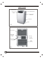
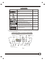
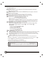
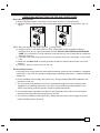
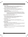
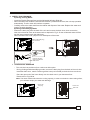
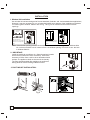
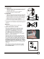
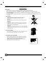
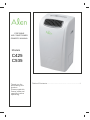
PORTABLE
AIR CONDITIONER
OWNER' S MANUAL
Models
C425
C535
Thank you for
purchasing this
product.
Please read this
Owner's Manual
carefully before
operating.
Table of Contents.................................. ......................1
CONTENTS
1.SAFETY RULES............................................................................. 1
2.NAMES OF PARTS.......................................................................... 2
3.ACCESSORIES................................................................................ 3
4.OPERATION PANEL OF THE AIR CONDITIONER........................ 3
5.OPERATING INSTRUCTION FOR THE AIR CONDITIONER ........ 5
6.INSTALLATION............................................................................... 8
7.MAINTENANCE...............................................................................10
8.TROUBLE SHOOTING....................................................................11
SAFETY RULES
1. Do not connect unit to any AC socket in disrepair.
2. Do not use in the following locations:
A: Next to source of fire
B: An area where oil is likely to splash.
C: An area exposed to direct sunlight.
D: An area where water is likely to splash.
E: Near a bath, a shower or a swimming pool.
3. Never insert your fingers or any foreign objects into the air outlet. Take
special care to warn children of these dangers.
4. Always store the unit upright in order to maintain the compressor in a
proper condition.
5. Be sure to unplug the unit before cleaning.
6. The heater must not be located immediately below a socket outlet.
7. If the appliance is covered, there is a risk of overheating.
8. If the plug or electrical cord is damaged, it must be replaced by the
manufacturer or its service agent or a similarly qualified person in order
to avoid a hazard.
1
NAMES OF PARTS
Operation Panel
Horizontal Louver
Vertical Louver
Blades
Carrying Handle
(both side)
Water Tank
Caster
Fig.1
Air Inlet (indoor)
Power Cord
Fixing Strap
(insert)
Drain Plug
Air Outlet
outdoor
Power Cord
and Plug
Air inlet
outdoor
Fig.2
2
Bottom Drain Plug
ACCESSORIES
PARTS :
PARTS NAME :
QUANTITY :
Duct
1
Adaptor A (for permanent duct mounting)
1
1
Adaptor B (for temporary duct mounting)
Expansion plug
4
Power Cord Fixing Strap
(for bundling the power cord)
1
Drain Hose(Continuous drainage)
1
Drain Hose(Connected with water tank)
1
1
Window Slider Kit
Check all the accessories are included in the package and please refer to the installation
instructions for their usage.
OPERATION PANEL OF THE AIR CONDITIONER
Digital Display
Timer on/off
indicator Lights
1
2
Signal receptor
(Not applicable to the
unit without remote control)
3
4
Mode indicator
Lights
Fan speed
indicator Lights
6
5
8
Water Full
indicator Lights
7
Power
indicator Lights
Fig.3
3
Key Pad Functions Fig.3
1
TIMER ON Button: Used to initiate the AUTO ON start time program, and used to
adjust Auto-Timer settings.
2
TIMER OFF Button: Used to initiate the AUTO OFF stop time program, and used to
3
adjust Auto-Timer settings.
Used to adjust (forward) temperature settings(1oC/2oF increments).
4
Used to adjust (backward) temperature settings(1oC/2oF increments).
5
MODE Button: Selects the appropriate operating mode:
Cool-Heat-Fan-Dry (Dehumidify).
Note:"Heat Mode" is for Heating/Cooling Model only.
MODE Indicator Lights(Green light): Illuminates under the different mode settings:
COOL Mode (
6
)--HEAT Mode(
)--FAN Mode(
)--DRY(Dehumidify) Mode (
)
FAN Button: Selects High-Medium-Low fan speeds
FAN Indicator Lights(Green light): Illuminates under the different mode settings:
High Fan Speed (
Fan Options:
)--Medium Fan Speed (
)--Low Fan Speed (
)
Cooling (3 speeds) High-Medium-LOW.
Heating (2 speeds) High-Low.
Dry-Dehumidifying (1 speed) High.
7
Fan (3 speeds) High-Medium-Low.
POWER Button: Power switch On/Off.
8
Water Full Indicator Light: Flashes red when the water level of the water tank exceeds
9
the maximum set level or if the water tank is not correctly positioned in the cabinet.
Digital Display Window: Shows the setting temperature and Auto-On/Off time. While
on DRY and FAN mode, it shows the room temperature.
Note: This appliance provides a feature that will allow you the option of setting temperatures in
Celsius
key pad &
or
Fahrenheit
key pad
. To change the temperature display on the main unit, press the
simultaneously
o
o
to alternate between the C & F scale.
o
.Celsius scale allows adjustments of 1 C increments.
Fahrenheit scale allows adjustment of 2oF increments.
Temperature Conversion Chart
O
C 10 11 12 13 14 15 16 17 18 19 20 21 22 23 24 25 26 27 28 29 30 31 32 33
O
F
4
48 50 52 54 56 58 60 62 64 66 68 70 72 74 76 78 80 82 84 86 88 90 92 94
OPERATING INSTRUCTING FOR THE AIR CONDITIONER
Before Starting This Unit
1) Select a suitable location, make sure you have easy access to an electrical outlet.
2) Install the Flexible Exhaust Hose and the Adjustable Window Slider Kit as depicted in Fig.4 &
Fig.4a
Fig.4
Fig.4a
NOTE: Step 2 is required only while using the cooling mode .
3) Plug the unit into a 220-240V~50Hz/ or 115V~ 60Hz (Refer to the nameplate located on
the right side of the unit.) grounded electrical outlet. DO NOT USE A REGULAR EXTENSION
CORD. If it is necessary to use an extension cord with this unit, use an approved air conditioner
extension cord only.
4) Insert the power cord fixing strap into the hole in the back of the unit, and bundle up the excess
cord.
5) Make sure the Water tank is correctly positioned inside the cabinet otherwise the unit will not
operate.
6) Press the on/off button to turn on the unit.
Electrical Requirement
1. All wiring must comply with local and national electrical codes and be installed by a qualified
electrician. If you have any questions regarding the following instructions, contact a qualified
electrician.
2. Check available power supply and resolve any wiring problems BEFORE installation and
operation of this unit.
3. For your safety and protection, this unit is grounded through the power cord plug when
plugged into a matching wall outlet. If you are not sure whether the wall outlets in your
home are properly grounded, please consult a qualified electrician.
4. The manufacturers nameplate is located on the right side panel of the unit and contains
electrical and other technical data specific to this unit.
5. To avoid the possibility of personal injury, always disconnect the power supply to the unit
before installing and/or servicing.
5
Operating Instructions
O
O
O
O
1 COOLING OPERATION (Operating temperature range: 17 C-32 C/62 F-92 F)
- Press the "MODE" button several times until the "COOL" indicator light comes on.
- Press the "TEMP SETTING" buttons " " or " " to select your desired room temperature.
The temperature can be set within a range of 17OC-30OC/62OF-88OF.
- Press the "FAN SPEED" button to choose the fan speed.
O
O
O
O
2 DEHUMIDIFYING OPERATION (Operating temperature range: 13 C-32 C/54 F-92 F)
- Press the "MODE" button several times until the "DRY" indicator light comes on.
- Under this mode, you cannot select a fan speed or adjust the temperature. The fan motor
operates at High speed.
- Keep windows and doors closed for the best dehumidifying effect.
- Do not put the duct to window.
CAUTION: During Cooling and dehumidifying modes, if the compressor cycle is interrupted
(unplugged, power failure, etc.) and reinstated immediately thereafter, a compressor
protection circuit is automatically self-affected. The compressor cannot operate during
a compressor protection condition. It may take about 3 minutes before the protection
circuit self-deactivates.(This is normal)
3 HEATING OPERATION (Cooling only type without heat feature)
O
O
O
O
(Operating temperature range:5 C-30 C/41 F-88 F)
-
Press the "MODE" button several times until the "HEAT" indicator light comes on.
Press the "TEMP SETTING" buttons " " or " " to select your desired room temperature.
The temperature can be set within a range of 17OC-30OC/62OF-88OF.
Press the "FAN SPEED" button to choose the fan speed.
Do not put the duct to window.
4 FAN OPERATION
- Press the "MODE" button several times until the "FAN " indicator light comes on.
- Press the "FAN SPEED" button to choose the fan speed. The temperature cannot be adjusted.
- Do not put the duct to window.
5 TIMER OPERATION
Setting the on timer:
- Press the "TIMER ON" button when the air conditioner is off.
- Continue pressing or keep pressing the "TIMER ON " button to select the time you need the unit
start to operate. The time is programmed as :0.5-1.0-1.5-2.0-2.5-3.0-3.5-4.0-4.5-5.0-5.5-6.0-6.57.0-7.5-8.0-8.5-9.0-9.5-10-11-12-13-14-15-16-17-18-19-20-21-22-23-24-0.0
- The starting time is adjustable from 0.0 to 24.
Setting the off timer:
- Press the "TIMER OFF" button when the air conditioner is on. Continue pressing or keep pressing
the button to select the time you need the unit turn off. The Operation Panel Window will display
"OFF TIME".
- The turning off time is adjustable from 0.00 to 24.
6
6
WATER TANK DRAINAGE
A) During Cooling Mode:
- Install the Flexible Exhaust Hose and the Adjustable Window Slider Kit .
- When the water level inside the internal tank reaches a predetermined level, the unit stop operation
automatically. The fan motor will continue to operate.
- Carefully remove the water tank from the cabinet and dispose of the water. Replace the water tank
back to its original position.
B) During Dehumidifying Mode:
- Remove the drain plug from the back of the unit and connect the drain hose, then connect the
other end of the drain hose to the water tank as depicted in Fig.5. So the condensed water will flow
into the internal tank through the drain hose.
- When the water tank is full, just pull it out and dispose of the water.
Remove the drain plug
from the back.
10mmMax
Fig.5
Remove the drain
plug and install the
drain hose.
7 CONTINUOUS DRAINAGE
- This unit also has provisions for a continuous drain option.
-
During Cooling and dehumidifying modes, remove the drain plug from the back of the unit, then
install the drain hose , attach a section garden hose (not included) to the drain hose connector.
Place the open end of the hose directly over the drain area in your basement floor.
Please refer to Fig.6 & 6a.
Note: This drain method will reduce the cooling capacity, in order to maintain the best cooling effect,
you had better employ the water tank drainage.
Remove the
drain plug
Connect the
drain hose
Fig.6
Fig.6a
7
INSTALLATION
1. Window Kit Installation
Your window kit has been designed to fit most standard Vertical and horizontal window applications,
However, it may be necessary for you to improvise/modify some aspects of the installation procedures
for certain types of window. Please refer to Fig. 7 & Fig. 7a for minimum and maximum window
openings.
Horizontal
window
Horizontal
window
Window Slider Kit
Minimum:67.5cm(2.22ft).
Maxmum:123cm(4.04ft).
Window Slider Kit
Minimum:67.5cm(2.22ft).
Maxmum:123cm(4.04ft).
Fig.7a
Fig.7
Note: If the window opening is less than the above mentioned minimum length of the window slider
kit, cut that one with a hole in it short to fit for the window opening. Do never cut out the hole
in window slider kit.
2. IMPORTANT:
Install the mobile air conditioner in a flat and spacious location
where the air outlets will not be covered up. A minimum
clearance of 30cm from a wall or other obstacles should
be kept. The appliance shall not be used in the laundry.
The plug shall accessible after appliance is positioned.
Wiring shall be done according to National rules.
1 2 in
che
s
12
3. DUCT MOUNT INSTALLATION:
Fig.9
8
Fig.8
in
ch
es
A) TEMPORARY1. Attach one end of the duct to the exhaust air outlet of the
mobile air condition, push it downwards, be sure to fix
thoroughly. (See Fig.9)
2. Attach the other end of the duct to adaptor B.
3. Put the end of duct to a nearby window.
Expansion plug
position
Adapter A
B) PERMANENT1. Attach one end of the duct to the exhaust air outlet of the
mobile air conditioner. According to the arrow direction,
push it downwards, be sure to fix thoroughly. (See Fig.9)
2. Install the adaptor A onto the wall by using 4 expansion
plugs and screws, be sure to fix thoroughly. (See Fig.10)
3. Attach the other end of the duct to adaptor A.
4. Cover the hole using the adaptor cap when not in use.
max 120CM
min 30CM
Fig.10
The duct can be compressed or extended between 20inches
and 78inches, but it is desirable to keep the duct length to a
minimum.
IMPORTANT:
DO NOT OVER BEND THE DUCT (SEE Fig.11)
4. WATER TANK SAFETY FEATURE
Fig.11
This unit is equipped with a water tank which
is fastened with a band to protect the water
level switch in transportation. Prior to the
first usage, remove the water tank from the
air conditioner and remove this band (see
figure 13). Return the water tank to it’s original
position in the air conditioner.
When the water level reaches a pre-determined
level within the tank, the digital display will show
"P1" and the water full indicator light will flash(red).
Carefully remove the water tank from the cabinet
and dispose of the water (see figure 14). Replace
the water tank back to its original position. The red
light will stop flashing and the "P1" will stop being
displayed.
Fig.12
Note: When you remove the water tank, please
do so slowly and gently to prevent from spilling
the condensed water.
Fig.13
9
MAINTENANCE
IMPORTANT:
1) BE SURE TO UNPLUG THE UNIT BEFORE CLEANING OR SERVICING.
2) DO NOT USE GASOLINE, THINNER OR OTHER CHEMICALS TO CLEAN THE UNIT.
3) DO NOT WASH THE UNIT DIRECTLY UNDER A TAP OR USING A HOSE. THE ELECTRICAL
CAUSE DANGER.
4) IF THE POWER CORD IS DAMAGED, IT SHOULD BE REPAIRED BY MANUFACTURE OR ITS
AGENCY.
1 AIR FILTER
- Clean the air filter at least once every two weeks to
prevent inferior fan operation because of dust.
- Removal
Pull out the filter cover and remove the air filter from the
filter cover.
- Cleaning
Wash the air filter by immersing it gently in warm water
(about 40OC/104OF) with a neutral detergent. Rinse the
filter and dry it in a shady place.
- Mounting
Attach the air filter to the filter cover using the attachment
hooks on the inner surface of the cover. Put the filter cover
back to the unit.
Fig.14
2 UNIT ENCLOSURE
- Use a lint-free cloth soaked with neutral detergent to clean
the unit enclosure. Finished by a dry clean cloth.
3 UNIT IDLE FOR A LONG TIME
-
Fig.15
When you plan to leave this unit unused for a long time,
remove the bottom rubber plug from the back hole and
attach a section of the continuous drain hose .
All the water in the bottom tray would drain outside
through the drain hose.(See Fig.16)
Fig.16
10
TROUBLE SHOOTING
TROUBLES
POSSIBLE CAUSES
SUGGEST REMEDIES
1. UNIT DOES NOT
- Water full indicator blinks, water tank
Dump the water in the water tank.
START WHEN
PRESSING
is full.
BUTTON
- Room temperature is higher than
Reset the temperature.
the set temperature.(Heating mode)
- Room temperature is lower than
Reset the temperature.
the set temperature.(Cooling mode)
2. NOT COOL ENOUGH
- The windows or doors in the room
are not closed.
- There are heat sources inside the
Make sure all the windows and
doors are closed.
Remove the heat sources if possible.
room.
- Exhaust air duct is not connected or
blocked.
3. POWER SHUT OFF AT
HEATING MODE
4. NOISY OR VIBRATION
- Temperature setting is too high.
Decrease the set temperature.
- Air filter is blocked by dust.
Clean the air filter.
- The automatic over heat protection
function. When the temperature at
O
O
the air outlet exceed 70 C/158 F,the
de vice will stop.
- The ground is not level or not flat
enough.
5. GURGLING SOUND
Connect the duct and make
sure it can function properly.
- The sound comes from the flowing
Switch on again after the unit has cool down.
Place the unit on a flat, level
ground if possible.
It is normal.
of the refrigerant inside the
air-conditioner.
6. COMPRESSOR DOES NOT
WORK AND THE DIGITAL
- The bottom tray is full
Remove the bottom drain plug and drain
the water outside.
DISPLAY AREA SHOWS
P2
11
One Year Limited Warranty
General
The Alen Corporation portable air conditioners are warranted for a period of one year from
the date of original purchase. Alen will, at its option, either furnish a replacement part or
replace your portable air conditioner provided the product is determined to be defective as a
result faulty material or workmanship while in normal use. Replacement parts or units will be
either new or refurbished. Alen’s sole obligation under this warranty is to replace, or at
Alen’s discretion, to repair, free of charge, all defective parts, for a period of one (1) year from
date of original purchase.
The replacement will be warranted for the unexpired portion of the original warranty. This
warranty will be valid only for units in possession of the original purchaser. Proof of
purchase must be presented to Alen’s warranty service representative. All parts or units that
are replaced become the property of Alen. To obtain warranty service, the defective product
or part must be shipped or delivered to: Alen’s authorized service center. All postage,
insurance and shipping charges are the responsibility of the Purchaser and are not included
in this warranty.
Exceptions
This warranty will not apply:
1. To malfunctions or damage other than caused by a defect in material or workmanship.
2. To any damage, abuse, accident, neglect or acts of nature.
3. To any filters or consumable parts
4. To damage as a result of misuse, tampering, or failure to follow any safety rules or
operating instruction.
5. To damage caused by repairs or alterations to the unit by anyone other than Alen
6. To any shipping or insurance costs related to the warranty service
For service please visit: www.alencorp.com
Miscellaneous
No one is authorized to make any other warranties on behalf of Alen. It is expressly
understood that the replacement warranty of Alen shall be in lieu of any and all other
warranties, express or implied, including warranties of merchantability or fitness for a
particular use or purpose, and further that Alen shall not be liable for any loss or damage
directly or indirectly arising from the use of the portable air conditioner, or for any
consequential damages arising from such use including damages from water leakage.
Alen’s sole liability with respect to any defect shall be for the replacement of the defective
part(s). Some states do not allow such limitations and exclusions, so the above may not
apply to you. This warranty gives specific legal rights. You may also have other rights which
vary from state to state.