1
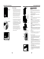
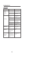
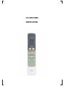
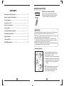
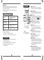
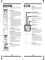
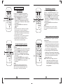
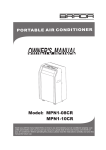
<,ϭϮWKZ
USER MANUAL
SOCIABLE REMARK
CONTENTS
SOCIABLE REMARK
Sociable remark..................................................................................................................................2
SAFETY PRECAUTIONS
Safety rules .......................................................................................................................................3
Operating condition ...........................................................................................................................3
Electrical information .........................................................................................................................4
IDENTIFICATION OF PARTS
Accessories .......................................................................................................................................4
Names of parts...................................................................................................................................5
AIR CONDITIONER FEATURES
Electronic control operating instructions ...........................................................................................6
OPERATING INSTRUCTIONS
Operating instructions .......................................................................................................................7
INSTALLATION INSTRUCTIONS
Location ............................................................................................................................................9
Window kit installation ......................................................................................................................9
Exhaust hose installation ................................................................................................................12
Water drainage ................................................................................................................................13
When using this air conditioner in the European countries, the following information must be followed:
DISPOSAL: Do not dispose this product as unsorted municipal waste. Collection of
such waste separately for special treatment is necessary.
It is prohibited to dispose of this appliance in domestic household waste.
For disposal, there are several possibilities:
A) The municipality has established collection systems, where electronic waste can be
disposed of at least free of charge to the user.
B) When buying a new product, the retailer will take back the old product at least free
of charge.
C) The manufacture will take back the old appliance for disposal at least free of charge
to the user.
D) As old products contain valuable resources, they can be sold to scrap metal dealers.
Wild disposal of waste in forests and landscapes endangers your health when
hazardous substances leak into the ground-water and find their way into the food chain.
CARE AND MAINTENANCE
Care and maintenance ....................................................................................................................14
TROUBLESHOOTING TIPS
Trouble shooting ..............................................................................................................................15
NOTE
The rating data indicated on the energy label is based
on the testing condition of installing the un-extended
air exhaust duct without adaptor A & B (The duct and
the adaptor A & B are listed in the accessories chart
of the Instruction Manual).
1
2
SAFETY PRECAUTIONS
IDENTIFICATION OF PARTS
Safety rules
To prevent injury to the user or other people and property damage, the following instructions must be
followed. Incorrect operation due to ignoring of instructions may cause harm or damage.
!
Always do this
Never do this
Do not operate your air conditioner in a wet room
such as a bathroom or laundry room.
Do not touch the unit with wet or damp hands or
when barefoot.
Do not press the buttons on the control panel with
anything other than your fingers.
Do not remove any fixed covers. Never use this
appliance if it is not working properly, or if it has
been dropped or damaged.
Never use the plug to start and stop the unit.
Always use the switch on the control panel.
Do not cover or obsturct the inlet or outlet grilles.
Do not use hazardous chemicals to clean or come
into contact with the unit. Do not use the unit in the
presence of inflammable substances or vapour such
as alcohol, insecticides, petrol,etc.
Do not allow children to operate the unit
unsupervised.
Do not use this product for functions other than
those described in this instruction manual.
Your air conditioner should be used in such a way
that it is protected from moisture. e.g. condensation,
splashed water, etc. Do not place or store your air
conditioner where it can fall or be pulled into water
or any other liquid. Unplug immediately.
Always transport your air conditioner in a vertical
position and stand on a stable, level surface during
use.
Turn off the product when not in use.
Always contact a qualified person to carry out
repairs. If the supply cord is damaged it must be
repaired by a qualified repairer.
Keep an air path of at least 30cm all around the
unit from walls, furniture and curtains.
If the air conditioner is knocked over during use,
turn off the unit and unplug from the mains supply
immediately.
WARNING
For your safety
Do not store or use gasoline or other flammable vapors and liquids in the vicinity of this or any other
appliance.
Avoid fire hazard or electric shock. Do not use an extension cord or an adaptor plug. Do not remove
any prong from the power cord.
WARNING
Electrical Infor mation
Be sure the electrical service is adequate for the model you have chosen. This information can be found
on the serial plate, which is located on the side of the cabinet and behind the grille.
Be sure the air conditioner is properly grounded. To minimize shock and fire hazards, proper grounding is
important. The power cord is equipped with a three-prong grounding plug for protection against shock
hazards.
Your air conditioner must be used in a properly grounded wall receptacle. If the wall receptacle you intend
to use is not adequately grounded or protected by a time delay fuse or circuit breaker, have a qualified
electrician install the proper receptacle.
Ensure the receptacle is accessible after the unit installation.
Accessories
PARTS :
PARTS NAME :
Energy Save
QUANTITY :
1 set
Exhaust hose and adaptor 1(supplied),
Use the unit in the recommended room size.
Locate the unit where furniture cannot obstruct the air flow.
Keep blinds/curtains closed during the sunniest part of the day.
Keep the filters clean.
Keep doors and windows closed to keep cool air in and warm air out.
or
adaptor B(round mouth or flat month:depending
on models) and Window Slider Kit and bolt(
)
1 set
Adaptor B(round mouth) ( )
Operating condition
Wall Exhaust Adaptor A(
The air conditioner must be operated within the temperature range indicated below:
MODE
ROOM TEMPERATURE
COOL
O
O
17OC(62OF)~35 C(95 F)
DRY
O
Expansion Plug and wooden screw( )
4/ pc
Foam seal ( )
3/pc
Remote Controller and Battery
(For remote control models only)
1set
Drain hose
1pc
O
SET TEMPERATURE( C)
FAN
HIGH
MED
LOW
TIMER ON
TIMER OFF
ON/OFF FAN SPEED
ECONOMY
TEMP
RESET LOCK
FOLLOW
LED
ME
DISPLAY TURBO
O
AUTO
COOL
DRY
HEAT
ION
O
O
5OC(41OF)~30 C(88 F)
SWING
HEAT(electrical heat type)
1 pc
13 C(55 F)~35OC(95OF)
MODE
HEAT(heat pump type)
)
O
<30 C/88 F
Note: Performance may be reduced outside of these operating temperatures.
Suggested tools for window kit installation
1. Screwdriver(medium size Phillips)
2. Tape measure or ruler
3. Knife or scissors
4. Saw(In the event that the window kit needs to be cut down in size because
the window is too narrow for direct installation)
3
NOTE: Optional parts( ), some models without.
Check all the accessories are included in the package and please refer to the installation instructions for
their usage.
NOTE: All the illustrations in this manual are for explanation purpose only. Your air conditioner
may be slightly different. The actual shape shall prevail.
4
IDENTIFICATION OF PARTS
AIR CONDITIONER FEATURES
ELECTRONIC CONTROL OPERATING INSTRUCTIONS
NAMES OF PARTS
1
Front
2
4
1
Operation Panel
2
Horizontal Louver Blade
(swing automatically)
3
Caster
4
Carrying Handle
(both sides)
3
Before you begin, thoroughly familiarize yourself with the control panel and remote controller
and all its functions, then follow the symbol for the functions you desire.
The unit can be controlled by the unit control panel alone or with the remote controller .
NOTE: This manual does not include Remote Controller Operations, see the <<Remote
Controller Instruction>> packed with the unit for details.
OPERATION PANEL OF THE AIR CONDITIONER
(The model has no
auto swing feature
withou t this button) 9
Fig.1
6
7
ION
AUTO
HEAT
1
MED
TIMER ON
DRY
SLEEP
5
1
Operation Panel
2
Horizontal Louver Blade
(manually)
3
Remote signal receptor
4
Caster
5
Carrying Handle
(both sides)
4
Fig.2
Rear
6
6
Upper Air Filter
(Behind the grille)
7
Air Outlet
8
Power cord outlet
9
Air intake
9
10
12
11
8
10 Drain Outlet
13
11
Exhaust hose
12
Air intake grille
13
Bottom tray drain outlet
Fig.4
1
3
2
6
1 MODE select button
Selects the appropriate operating mode.
Each time you press the button, a mode
is selected in a sequence that goes from
AUTO, COOL, DRY, FAN and HEAT(cooling
only models without). The mode indicator light
illuminates under the different mode settings
Fig.4.
4
LOW
5
UP(
) and DOWN( ) button
Used to adjust (increasing/decreasing)
temperature settings(1 C/2 F increments)
in a range of 17 C(62 F) to 30 C(88 F) or
the TIMER setting in a range of 0~24hrs..
NOTE: The control is capable of displaying
temperature in degrees Fahrenheit or degrees
Celsius. To convert from one to the other, press
and hold the Up and Down buttons at the same
time, for 3 seconds.
2 TIMER button
Used to initiate the AUTO ON start time and
AUTO OFF stop time program, in conjuction
with the
&
buttons.
7
3 POWER button
Power switch on/off.
LED Display
Shows the set temperature in " OC " or
O
" F" and the Auto-timer settings.
While on DRY and FAN modes, it shows
the room temperature.
Error codes:
E1- Room temperature sensor errorUnplug the unit and plug it back in.
If error repeats, call for service.
E2- Evaporator temperature sensor errorUnplug the unit and plug it back in.
If error repeats, call for service.
E4- Display panel communication errorUnplug the unit and plug it back in.
If error repeats, call for service.
P1- Bottom tray is full - Connect the
drain hose and drain the collected
water away. If error repeats, call
for service.
4 SLEEP button
Used to initiate the SLEEP operation.
5 FAN button
Control the fan speed. Press to select the fan
speed in four steps-LOW, MED, HI and AUTO.
The fan speed indicator light illuminates under
different fan settings except AUTO speed. When
select AUTO fan speed, all the fan indicator lights
turn dark.
Fig.3
5
FAN
TIMER OFF
FAN
7
C
MODE
3
HI
COOL
F
Model B
8
SWING
Model A
2
6
Remote signal receptor
(Some models have the
signal receptor on the
front panel , Fig.2)
6
OPERATING INSTRUCTIONS
OPERATING INSTRUCTIONS
-
8 ION button(optional)
Press the ION button, the ion generator
is ener gized and will help to remove
pollen and impur ities from the air, and
trap them in the filter. Press it again to
stop the function.
The air conditioner will control room
temperature automatically round the
temperature point set by you.
Under AUTO mode, you can not
select the fan speed.
-
FAN operation
- Press the "MODE" button until the
"FAN " indicator light comes on.
- Press the "FAN SPEED" button to
choose the fan speed. The temperature
cannot be adjusted.
- Do not put the duct to window.
9 SWING button
(Applicable to the models with auto swing feature only)
When the operation is ON, press the
SWING button can stop the louver at
the desired angle. The louver swing up
to an angle of 6 O for each press. Keep
pressing the button more than 2 seconds
can initiate the auto swing feature.
Other features
Power Outage
In the case of a power outage or interruption,
the unit will auto matically re-start, in the
settings ast used, after the power is restored.
Wait 3 minutes before resuming operation
After the unit has stopped, it can not be restarted
operation in the first 3 minutes. This is to protect
the unit. Operation will automatically start after
3 minutes.
Adjust manually
TIMER operation
-
Operating Instructions
COOL operation
- Press the "MODE" button until the "COOL"
indicator light comes on.
- Press the ADJUST buttons "¡" or " " to
select your desired room temperature. The
temperature can be set within a range of
17OC-30OC/62OF-88OF.
- Press the "FAN SPEED" button to choose the
fan speed.
-
¡
-
HEAT operation(cooling only models without)
- Press the "MODE" button until the "HEAT"
indicator light comes on.
- Press the ADJUST buttons "¡" or " " to
select your desired room temperature. The
temperature can be set within a range of
17OC-30OC/62OF-88OF.
- Press the "FAN SPEED" button to choose the
fan speed. For some models, the fan speed
can not be adjusted under HEAT mode.
-
¡
-
-
DRY operation
- Press the "MODE" button until the "DRY" indicator
light comes on.
- Under this mode, you cannot select a fan speed or
adjust the temperature. The fan motor operates at
LOW speed.
- Keep windows and doors closed for the best
dehumidifying effect.
- Do not put the duct to window.
AUTO operation
- When you set the air conditioner in AUTO
mode, it will automatically select cooling,
heating(cooling only models without), or fan
only operation depending on what temperature
you have selected and the room temperature.
7
When the unit is on, first press the
Timer button, the TIMER OFF
indicator light illuminates. It indicates the Auto Stop program is
initiated.
When the unit is off, first press the
Timer button, the TIMER ON indicator light illuminates. It indicates
the Auto Start program is initiated.
Press or hold the UP or DOWN
button to change the Auto time by
0.5 hour increments, up to 10 hours,
then at 1 hour increments up to 24
hours. The control will count down
the time remaining until start.
The selected time will register in 5
second and the system will automatically revert back to display the
previous temperature setting.
Turning the unit ON or OFF at any
time or adjusting the timer setting
to 0.0 will cancel the Auto Start/
Stop timed program.
When the malfunction (E1,E2or E4)
occurs, the Auto Start/Stop timed
program will also be cancelled.
SLEEP operation
Press this button, the selected temperature
will increase(cooling) or decrease(heating)
O
O
by 1 C/2 F 30 minutes.The temperature
will then increase(cooling) or decrease
O
O
(heating) by another 1 C/2 F after an
additional 30 minutes. This new temperature will be maintained for 7 hours
before it returns to the originally selected
temperature. This ends the Sleep mode
and the unit will continue to operate as
originally programmed.
NOTE: This feature is unavailabe under
FAN or DRY mode.
Air flow direction adjustment
The louver can be adjusted manually or
automatically according to the different models.
Fig.5
Swing automatically
Adjust the air flow direction manually
(Fig.5):
The louver can be set to the desired position
manually. The max setting angle is about
60 O, please do not force to set any larger.
Do not place any heavy objects or other loads
on the louver, doing so will cause damage to
the unit.
Ensure the louver is fully opened under
heating operation.
Keep the louver fully opened during
operation.
Adjust the air flow direction automatically
(Fig.6):
When operation is ON, the louver opens fully.
Use the SWING button on the remote
controller can stop the louver at the desired
angle.
The louver move up to an angle of 6 O for
each press until it move to a position which
would affect the cooling or heating effect
of the air conditioner, it would automatically
change the swing direction.
If keep pressing the SWING button more
than 2 seconds, the auto swing feature is
activated. The louver swings as shown in
Fig.6
Fig.6
8
INSTALLATION INSTRUCTIONS (optional)
INSTALLATION INSTRUCTIONS (optional)
INSTALLATION INSTRUCTIONS
Foam seal A
(adhesive type)
Location
or
30c
30
m
cm
30c
c
30
m
Fig.7
Horizontal
window
m
The air conditioner should be placed on a firm
foundation to minimize noise and virbration. For
safe and secure positioning, place the unit on a
smooth, level floor strong enough to support the unit.
The unit has casters to aid placement, but it should
only be rolled on smooth, flat surfaces. Use caution
when rolling on carpet surfaces. Do not attempt to
roll the unit over objects.
The unit must be placed within reach of a properly
rated grounded socket.
Never place any obstacles around the air inlet or
outlet of the unit.
Allow at least 30cm of space from the wall for
efficient air-conditioning.
Fig.10
Window kit
26.5 ~ 48
or
Horizontal
window
Window Slider Kit
Minimum:67.5cm(2.22ft).
Maxmum:123cm(4.04ft).
Fig.8
2. Attach the window slider kit to the window stool.
Adjust the length of the window slider kit according
to the width of window, shorten the adjustable window
kit if the width of window is less than 27 inches.
Open the window sash and place the window slider
kit on the window stool. Fig.11
3. Cut the foam seal(adhesive type) to the proper
length and attach it on the top of the window. Shown
as in Fig.12.
Window Slider kit Installation
Your window slider kit has been designed to fit most
standard "Vertical" and "horizontal"window
applications, However, it may be necessary for you to
improvise/modify some aspects of the installation
procedures for certain types of window. Please refer
to Fig. 8& Fig.9 for minimum and maximum window
openings.Window slider kit can be fixed with a bolt
(see Fig.9a).
1. Cut the foam seal(adhesive type) to the proper
length and attach it to the window stool. Fig.10
Window stool
Window Slider Kit
Minimum:67.5cm(2.22ft).
Maxmum:123cm(4.04ft).
or
Installation in a double-hung sash
window
Window kit
4. Close the window sash securely against the
window.
26.5 ~ 48
Window stool
Fig.11
Note: If the window opening is less than the mentioned
minimum length of the window slider kit, cut that one
with a hole in it short to fit for the window opening. Do
never cut out the hole in window slider kit.
5. Cut the foam seal to an appropriate length and
seal the open gap between the top window sash
and outer window sash. Shown as in Fig.13.
Window kit
or
Window stool
Horizontal
window
Window kit
Window Slider Kit
Minimum:67.5cm(2.22ft).
Maxmum:123cm(4.04ft).
bolt
bolt
or
or
Window slider kit
Window stool
Window
slider kit
Foam seal
Horizontal
window
Window Slider Kit
Minimum:67.5cm(2.22ft).
Maxmum:123cm(4.04ft).
Fig.12
Fig.9a
Fig.13
Fig.9
9
10
INSTALLATION INSTRUCTIONS (optional)
Foam seal A
(adhesive type)
INSTALLATION INSTRUCTIONS
Exhaust hose installation:
Installation in a sliding sash
window
The exhaust hose and adaptor must be installed or removed
in accordance with the usage mode.
Exhaust hose
Fig.14
Window
panel
26.5 ~ 48
1. Cut the foam seal(adhesive type) to the proper
length and attach it to the window frame,Fig.14.
2. Attach the window slider kit to the window stool.
Adjust the length of the window slider kit according
to the width of window, shorten the adjustable window
kit if the width of window is less than 27 inches.
Open the window sash and place the window slider
kit on the window stool. See Fig.15.
3. Cut the foam seal(adhesive type) to the proper
length and attach it on the top of the window.
Shown as in Fig.16.
or
Fig.18
Use the screws to
install the flat mouth
Flat mouth
Flat mouth
Adaptor 1
Fig.19a
4. Close the sliding sash securely against the window.
5. Cut the foam seal to an appropriate length and
seal the open gap between the top window sash
and outer window sash. Shown as in Fig.17.
Fig.15
Push in
Hook
Fig.20
Expansion plug
position
Adaptor A
Adaptor
cap
or
max 120CM
Fig.16
Install
FAN,DEHUMIDIIFY or HEAT(electrical heat type) Remove
mode
For the first time to use the machine, take the exhaust hose
out as shown in Fig.18.
1. Install the adaptor B and adaptor I onto the exhaust hose as
shown in Fig.19a or Fig.19b. Refer to the previous pages for
window kit installation.
2. Place the Exhaust hose over against the air outlet opening
hook and flat the other end(See Fig.20) for quick installation.
Note:
Extend the both ends of the exhaust hose to a length of
30~50mm before install the adaptor B and apaptor I onto
the exhaust hose.
Fig.19b
Window
panel
26.5 ~ 48
COOL,HEAT(heat pump type) or AUTO
mode
min 30CM
The exhaust hose can be installed into the wall
(Not applicable to the units without adaptor A, expansion
plugs and wooden screws of Accessories ).
1. Prepare a hole in the wall. Install the wall Exhaust adaptor A
onto the wall(outside) by using 4 expansion plugs and
wooden screws, be sure to fix thoroughly. (See Fig.21)
2. Attach the Exhaust hose installed adaptor B (round mouth) to
wall Exhaust adaptor A.
Note:
Cover the hole using the adaptor cap when not in use.
The exhaust hose can be compressed or extended
moderately according to the installation requirement,
but it is desirable to keep the hose length to a minimum.
IMPORTANT:
DO NOT OVER BEND THE EXHAUST HOSE (SEE Fig.22)
Fig.21
Foam seal
Fig.17
Fig.22
11
12
CARE AND MAINTENANCE
INSTALLATION INSTRUCTIONS
Air filter
(slide out)
Water drainage:
Remove the
drain plug
-
CARE AND MAINTENANCE
During dehumidifying modes, remove the drain
plug from the back of the unit, install the drain
connector(5/8 universal female mender) with
3 4 hose(locally purchased). For the models
without drain connector, just attach the drain
Fig.26
hose to the hole. Place the open end of the
Remove three
screws and
take the air
intake grille
down
hose directly over the drain area in your
basement floor. Please refer to Fig.23 & 24.
Fig.23
-
When the water level of the bottom tray reaches
IMPORTANT:
1) Be sure to unplug the unit before cleaning or servicing.
2) Do not use gasoline, thinner or other chemicals to clean
the unit.
3) Do not wash the unit directly under a tap or using a hose.
It may cause electrical danger.
4) If the power cord is damaged, it should be repaired by
manufacture or its agency.
1. Air filter
-
a predetermined level, the unit beeps 8 times,
Continuous
drain hose
the digital display area shows "P1" . At this time
the air conditioning/dehumidification process will
Fig.27
immediately stop. However, the fan motor will
-
continue to operate(this is normal).
Carefully move the unit to a drain location,
-
remove the bottom drain plug and let the
water drain away(Fig.25). Restart the machine
until the "P1" symbol disappears. If the error
repeats, call for service.
Fig.24
Remove the air filter
Fig.28
out from the grille
Clean the air filter at least once every two weeks to prevent
inferior fan operation because of dust.
Removal
This unit has two filter. Grasp the upper filter tab(Fig.26),
,,
,,
pull the filter out,, then up,,. Remove the lower filter by
loosening the screws, taking down the air inlet grille, then
removing the air filter as shown in Fig.27 & 28.
Cleaning
Wash the air filter by immersing it gently in warm water
(about 40OC/104OF) with a neutral detergent. Rinse the filter
and dry it in a shady place.
Mounting
Insert the upper air filter from upward after cleaning, attach
the lower air filter to the air inlet grille, then install the grille
by using the screws. Make sure the screws are securely
fastened.
2. Unit enclosure
- Use a lint-free cloth soaked with neutral detergent to clean
the unit enclosure. Finished by a dry clean cloth.
Band
3. Unit idle for a long time
-
Power
cord
Fig.29
Fig.25
-
-
-
Remove the rubber plug at the back of the unit and attach
a hose to drain outlet. Place the open end of the hose
directly over the drain area in your basement floor
(See Fig.23 & 24).
Remove the plug from the bottom drain outlet, all the water
in the bottom tray would drain out (See Fig.25).
Keep the appliance running on FAN mode for half a day in
a warm room to dry the appliance inside and prevent mold
forming.
Stop the appliance and unplug it, wrapped the cord and
bundle it with the tape(Fig.29). Remove the batteries from
the remote controller.
Clean the air filter and reinstall it.
Unscrew the exhaust hose to the right or left and pull out
for uninstallation(Fig.30), keep it safety or place behind
the air intake grille, and cover the window(wall) hole with
the adaptor cap.
Fig.30
13
14
TROUBLESHOOTING TIPS
TROUBLE SHOOTING
TROUBLES
POSSIBLE CAUSES
SUGGEST REMEDIES
1. Unit does not
- P1 appears in the display window
Drain the water in the bottom tray.
Start when
Pressing on/off
Button
- Room temperature is lower than
the set temperature.(Cooling mode)
- The windows or doors in the room
are not closed.
2. Not cool enough
- There are heat sources inside the
Remove the heat sources if possible.
room.
blocked.
Connect the duct and make
sure it can function properly.
- Temperature setting is too high.
Decrease the set temperature.
- Air filter is blocked by dust.
Clean the air filter.
- The ground is not level or not flat
Place the unit on a flat, level
enough.
5. Gurgling sound
Make sure all the windows and
doors are closed.
- Exhaust air duct is not connected or
4. Noisy or vibration
Reset the temperature.
ground if possible.
- The sound comes from the flowing
It is normal.
of the refrigerant inside the
air-conditioner.
6. Power shut off at
Heating mode
- The automatic over heat
protection function. When the
temperature at the air outlet
O
O
exceed 70 C/158 F,th e de vice
will st op.
15
Switch on again after the unit
has cool down.
AIR CONDITIONER
REMOTE CONTROL
Handling the remote controller
CONTENTS
Location of the remote controller.
Use the remote controller within a distance of 8
meters from the appliance, pointing it towards the
receiver. Reception is confirmed by a beep.
Handling the remote controller ...................................................... 2
Remote controller Specifications...................................................
3
Function buttons .................. .........................................................
4
8m
SET
AUTO
CO
OL
DRY
HEAT
TEM
PERAT
URE(
C)
FAN
HIG
H
ME
D
LOW
TEM
P
MO
DE
Indicators on LCD ..........................................................................
6
ON
/OF
F
SW
ING
FAN
ECON
SPEE
D
OM
Y
ION
TIM
ER
RES
ET
FOL
LOW
ME
ON
LOC
K
TIM
ER
LED
DIS
PLA
Y TU
OFF
RBO
How to use the buttons .................................................................
7
Auto operation.................................................................................
7
Cooling/Heating/Fan operation......................................................
7
Dehumidifying operation ...............................................................
8
Swing operation..............................................................................
8
Timer operation...............................................................................
9
ECONOMY operation ....................................................................
12
CAUTIONS
The air conditioner will not operate if curtains, doors or other materials
block the signals from the remote controller to the indoor unit.
Prevent any liquid from falling into the remote controller. Do not expose
the remote controller to direct sunlight or heat.
If the infrared signal receiver on the indoor unit is exposed to direct
sunlight, the air conditioner may not function properly. Use curtains to
prevent the sunlight from falling on the receiver.
If other electrical appliances react to the remote controller. either move
these appliances or consult your local dealer.
Replacing batteries
The remote controller is powed by two dry
batteries(R03/LR03X2) housed in the rear
part and protected by a cover.
(1) Remove the cover by pressing and sliding off.
(2) Remove the old batteries and insert the new
batteries,placing the(+) and (-) ends correctly.
(3) Reattach the cover by sliding it back into
position.
.
1
NOTE: When the batteries are removed, the
remote controller erases all programming.
After inserting new batteries, the remote
controller must be reprogrammed.
2
CAUTIONS
Function buttons
1 TEMP UP Button
Do not mix old and new batteries or batteries of a different type.
Do not leave the batteries in the remote controller if it is not going
to be used for 2 or 3 months.
Dispose of the old batteries in the special containers to be found
in the sales outlets.
Push this button to increase the indoor temperature setting in 1oC(2 F) increments to 30oC(88 F).
SET TEMPERATURE( C)
Remote Controller Specifications
Rated Voltage
Push this button to decrease the indoor temperature setting in 1oC(2 F) increments to 17oC(62 F).
TEMP
1
Model
2 TEMP DOWN Button
FAN
HIGH
MED
LOW
AUTO
COOL
DRY
HEAT
R51I13/BG(C)E, R51I14/BG(C)E,
R51I15/BG(C)E, R51I16/BG(C)E,
R51I17/BG(C)E.
4
3.0V(Dry batteries R03/LR03¡2)
5
MODE
ON/OFF FAN SPEED
3
SWING
ECONOMY
RESET LOCK
TIMER ON
TIMER OFF
LED
DISPLAY
Lowest Voltage of
CPU Emitting Signal
2.0V
Signal Receiving
Range
8m (when using 3.0 voltage,
it Gets 11m)
Environment
¡
¡
-5C ~60C(
-41OF~140O)F
NOTE:
Temperature setting display:
Celsius scale( C): R51I14/BG(C)E, R51I16/BG(C)E.
Fahrenheit scale( F): R51I13/BG(C)E, R51I15/BG(C)E, R51I17/BG(C)E.
Performance Feature
2
6
7
8
9
10
11
12
3 MODE Button
Each time the button is pressed, the operation
mode is selected in the sequence of the following:
AUTO
DRY
HEAT
FAN
NOTE: Heat mode is for Cooling & Heating models only.
4
SWING Button(on some models)
Used to stop or start louver movement and
set the desired up/down airflow direction.
5
RESET Button
Once the recessed RESET button is pressed,
all of the current settings will be cancelled
and the controller will return to the initial settings.
6
ON/OFF Button
Operation starts when this button is pressed
and stops when the button is pressed again.
7
FAN SPEED Button
Used to select the fan speed in four steps:
Auto Low Med High
Model: R51I14/BG(C)E,
R51I16/BG(C)E.
NOTE:
R51I16/BG(C)E models
have no SWING feature.
COOL
8 TIMER ON Button
1. Operating Mode: AUTO, COOL, DRY, HEAT(Cooling only
model without), and FAN.
2. Timer Setting Function in 24 hours.
¡
¡
3. Indoor Setting Temperature Range : 17C~30C(62OF~88OF).
4. Full function of LCD (Liquid Crystal Display)
5. Back light emitting.
Press this button to activate the Auto-on time
setting. Each press will increase the time setting
in 30 minutes increments, up to 10 hours, then at
1 hour increments up to 24 hours. To cancel the
Auto-on time setting, just press the button until
the time setting is 0.0.
9 ECONOMY(SLEEP) Button
Select this function during the sleeping time. It
can maintain the most comfortable temperature
and save energy. This function is available on
COOL, HEAT or AUTO mode only .
3
4
Indicators on LCD
Function buttons(continued)
SET TEMPERATURE( F)
FAN
HIGH
MED
LOW
AUTO
COOL
DRY
HEAT
Press this button to activate the Auto-off time
setting. Each press will increase the time setting
in 30 minutes increments, up to 10 hours, then at
1 hour increments up to 24 hours. To cancel the
Auto-off time setting, just press the button until
the time setting is 0.0.
ON/OFF FAN SPEED
SWING
ECONOMY TIMER ON
RESET LOCK
Press this recessed button to lock all current
settings, and the remote controller will not accept
any operation except that of the LOCK. Use the
LOCK mode when you want to prevent settings
from being changed accidentally. Press the LOCK
button again to cancel the LOCK function. A lock
symbol will appear on the remote controller display
when the lock function is activated.
Model: R51I13/BG(C)E,
R51I15/BG(C)E.
NOTE: R51I15/BG(C)E
models hav e no SWING
feature.
FAN
HIGH
MED
LOW
TEMP
ON/OFF FAN SPEED
SWING
SLEEP
ION
RESET LOCK
12
LED Display Button
Press this button to clear the display on the
indoor unit, press it again to light the display .
13 FOLLOW ME Button
Press this button to initiate FOLLOW ME function.
When the Follow Me function is activated, the
remote display is actual temperature at its location.
The remote control will send this signal to the air
conditioner every 3 minutes interval until press
the Follow Me button again.
The Follow Me function is not available under
DRY and FAN mode.
Switch the operation mode or turn off the unit will
cancel the follow me function automatically.
SET TEMPERATURE( F)
MODE
TIMER ON
TIMER OFF
Transmission Indicator
This transmission indicator will light when remote
controller transmits signals to the indoor unit.
Temp./Timer display
The temperature setting (from 17OC(62O F) to
30OC(88OF)) or timer setting (0~24h) will be displayed.
If FAN mode is selected, there will be no display.
11 LOCK Button
TIMER OFF
LED
DISPLAY
AUTO
COOL
DRY
HEAT
Displays the current selected mode. Including AUTO,
COOL, DRY, HEAT (cooling & heating models only)
and FAN.
10 TIMRT OFF Button
TEMP
MODE
MODE display
NOTE: While the unit is running under Energy-saving
mode, it would be cancelled if any other buttons are
pressed.
9
FOLLOW
LED
ME
DISPLAY
14 ION Button
When push this button, the ion generator is
energized and will help to remove pollen and
impurities from the air.
ON/OFF display
This indicator will be displayed when
the unit is operating.
MODE display(FAN mode)
SET TEMPERATURE
FAN SPEED display
TIMER ON OFF
Displays the selected fan speed: AUTO, HIGH, MED
and LOW. Nothing displays when the fan speed is
selected in AUTO speed. When AUTO or DRY Mode
is selected, there will be no signals displayed.
TIMER display
This display area shows the settings of the TIMER.
That is, if only the Auto-on time function is set, it will
display TIMER ON. If only the Auto-off time function
is set, it will display TIMER OFF. If both functions are
set, it will display TIMER ON OFF which indicates you
have chosen both the Auto-on time and Auto-off time.
LOCK Indicator
LOCK display is displayed when pushing the LOCK
button. Push the LOCK button to clear display.
13
14
Model: R51I17/BG(C)E
5
6
How to use the buttons
Dehumidifying operation
SET TEMPERATURE( C)
Auto operation
FAN
HIGH
MED
LOW
AUTO
COOL
DRY
HEAT
TEMP
2
ON/OFF FAN SPEED
MODE
3
1
SWING
ECONOMY
RESET LOCK
TIMER ON
TIMER OFF
LED
DISPLAY
Ensure the unit is plugged in and power is
available. The OPERATION indicator on the
display panel of the indoor unit illuminates.
1. Press the MODE button to select Auto.
2. Press the TEMP button to set the desired
temperature. The temperature can be set
within a range of 17 C(62 F)~ 30 C in 1 C(2 F)
increments.
3. Press the ON/OFFbutton to start the air
conditioner.
NOTE
SET TEMPERATURE( C)
FAN
HIGH
MED
LOW
AUTO
COOL
DRY
HEAT
TEMP
2
ON/OFF FAN SPEED
MODE
1
SWING
TIMER ON
ECONOMY
TIMER OFF
RESET LOCK
LED
DISPLAY
In the Dehumidifying mode, you can not switch
the fan speed. It has already been automatically
controlled.
1. In the Auto mode, the air conditioner can logically
choose the mode of Cooling, Fan, Heating and
Dehumidifying by sensing the difference between the
actual ambient room temperature and the set temperature on the remote controller.
2. In the Auto mode, you can not switch the fan speed.
It has already been automatically controlled.
3. If the Auto mode is not comfortable for you , the
desired mode can be selected manually.
Swing operation(on some models)
SET TEMPERATURE( C)
SET TEMPERATURE( C)
Cooling /Heating/Fan operation
FAN
HIGH
MED
LOW
AUTO
COOL
DRY
HEAT
TEMP
2
MODE
1
ON/OFF FAN SPEED
4
3
SWING
ECONOMY
RESET LOCK
TIMER ON
TIMER OFF
LED
DISPLAY
Ensure the unit is plugged in and power is
available.
1. Press the MODE button to select COOL, HEAT,
(cooling & heating models only) or FAN mode.
2. Press the TEMP button to set the desired
temperature. The temperature can be set
within a range of 17 C(62 F)~ 30 C in 1 C(2 F)
increments.
3. Press the FAN SPEED button to select the
fan speed in four steps- Auto, Low, Med,or High.
4. Press the ON/OFF button to start the air
conditioner.
NOTE
In the FAN mode, the setting temperature is not
displayed in the remote controller and you are not
able to control the room temperature either. In this
case, only step 1, 3 and 4 may be performed.
7
3
Ensure the unit is plugged in and power is
available. The OPERATION indicator on the
display panel of the indoor unit illuminates.
1. Press the MODE button to select DRY mode.
2. Press the TEMP button to set the desired
temperature. The temperature can be set
within a range of 17 C(62 F)~ 30 C in 1 C(2 F)
increments.
3. Press the ON/OFF button to start the air
conditioner.
NOTE
FAN
HIGH
MED
LOW
AUTO
COOL
DRY
HEAT
TEMP
MODE
1
SWING
ON/OFF FAN SPEED
ECONOMY
RESET LOCK
TIMER ON
TIMER OFF
LED
DISPLAY
Use the SWING button to adjust the Up/Down
airflow direction.
1. When press the button once and quickly, the
air flow direction setting feature of the louver is
activated. The moving angle of the louver is
6o for each press. Keep pressing the button to
move the louver to the desired position.
2. If keep pressing the SWING button without
releasing for 2 more seconds, the auto swing
feature of the louver is activated. The horizontal
louver would swing up/down automatically.
Press it again to stop.
NOTE: When the louver swing or move to a
position which would affect the cooling
and heating effect of the air conditioner,
it would automatically change the swing/
moving direction.
8
Timer operation
press the TIMER ON button can set the auto-on
time of the unit. And press the TIMER OFF button
can set the auto-off time of the unit.
SET TEMPERATURE( C)
AUTO
COOL
DRY
HEAT
FAN
HIGH
MED
LOW
TIMER ON
TEMP
MODE
SWING
ON/OFF FAN SPEED
ECONOMY TIMER ON
1
RESET LOCK
TIMER OFF
2
LED
DISPLAY
To set the Auto-on time.
1. Press the TIMER ON button. The remote
controller shows TIMER ON, the last Auto-on
setting time and the signal "h" will be shown on
the LCD display area. Now it is ready to reset the
Auto-on time to START the operation.
2. Push the TIMER ON button again to set desired
Auto-on time. Each time you press the button,
the time increases in 30 minutes increments, up
to 10 hours, then at 1 hour increments up to 24
hours.
3. After setting the TIMER ON ,there will be a onehalf second delay before the remote controller
transmits the signal to the air conditioner. Then,
after approximately another 2 seconds, the
signal "h" will disappear and the set temperature
will re-appear on the LCD display window.
To set the Auto-off time.
1. Press the TIMER OFF button. The remote
controller shows TIMER OFF, the last Auto-off
setting time and the signal "h" will be shown on
the LCD display area. Now it is ready to
reset the Auto-off time to START the operation.
2. Push the TIMER OFF button again to set desired
Auto-off time. Each time you press the button,
the time increases in 30 minutes increments, up
to 10 hours, then at 1 hour increments up to 24
hours.
3. After setting the TIMER OFF ,there will be a onehalf second delay before the remote controller
transmits the signal to the air conditioner. Then,
after approximately another 2 seconds, the
signal "h" will disappear and the set temperature
will re-appear on the LCD display window.
9
IMPORTANT
The effective operation time set by the remote controller for the timer
function is limited to the following settings: 0.5, 1.0, 1.5, 2.0, 2.5, 3.0,
3.5, 4.0, 4.5, 5.0, 5.5, 6.0, 6.5, 7.0, 7.5, 8.0, 8.5, 9.0, 9.5, 10, 11, 12, 13,
14, 15,16,17, 18, 19, 20, 21, 22, 23 and 24.
Example of Timer setting
TIMER ON
(Auto-on Operation)
The TIMER ON feature is useful when you want
the unit to turn on automatically before say when
you return home. The air conditioner will automatically start operating at the set time.
h
TIMER ON
Start
Off
Set
6 hours later
Example:
To start the air conditioner in 6 hours.
1. Press the TIMER ON button, the last setting of
starting operation time and the signal "h" will
show on the display area.
2. Press the TIMER ON button to display "6:0h" on
the TIMER ON display of the remote controller.
3. Wait for about 3 seconds and the digital display
area will show the temperature again. Now this
function is activated.
10
TIMER OFF
TIMER OFF
Example:
To stop the air conditioner in 10 hours.
1. Press the TIMER OFF button, the last setting of
stopping operation time and the signal "h" will
show on the display area.
2. Press the TIMER OFF button to display "10h" on
the TIMER OFF display of the remote controller.
3. Wait for about 3 seconds and the digital display
area will show the temperature again. Now this
function is activated.
Stop
On
Set
10 hours later
COMBINED TIMER
(Setting both ON and OFF timers simultaneously)
h
TIMER ON OFF
Start
Stop
On
Set
h
(Auto-off Operation)
The TIMER OFF feature is useful when you want
the unit to turn off automatically after you go to bed.
The air conditioner will stop automatically at the set
time.
h
2 hours later
after setting
10 hours later
after setting
TIMER OFF ¡ TIMER ON
(On ¡ Stop ¡ Start operation)
This feature is useful when you want to stop the air
conditioner after you go to bed, and start it again in
the morning when you wake up or when you return
home.
Example:
To stop the air conditioner 2 hours after setting
and start it again 10 hours after setting.
1. Press the TIMER OFF button.
2. Press the TIMER OFF button again to
display 2.0h on the TIMER OFF display.
3. Press the TIMER ON button.
4. Press the TIMER ON button again to
display 10h on the TIMER ON display .
5. Wait for the remote control to display
the setting temperature.
11
TIMER ON OFF
Start
Stop
Off
Set
2 hours later
after setting
5 hours later
after setting
TIMER ON ¡ TIMER OFF
(Off ¡ Start ¡ Stop operation)
This feature is useful when you want to start
the air conditioner before you wake up and
stop it after you leave the house.
Example:
To start the air conditioner 2 hours after
setting, and stop it 5 hours after setting.
1. Press the TIMER ON button.
2. Press the TIMER ON button again to
display 2.0h on the TIMER ON display.
3. Press the TIMER OFF button.
4. Press the TIMER OFF button again to
display 5.0h on the TIMER OFF display .
5. Wait for the remote control to display
the setting temperature.
! CAUTION
The timer setting(TIMER ON or TIMER OFF) that in
sequence occurs directly after the set time will be
activated first.
SET TEMPERATURE( C)
ECONOMY(SLEEP) operation
FAN
HIGH
MED
LOW
AUTO
COOL
DRY
HEAT
TEMP
MODE
SWING
ON/OFF FAN SPEED
ECONOMY
RESET LOCK
TIMER ON
TIMER OFF
LED
DISPLAY
1
When you press the ECONOMY button, the
economic running function will be activated,
the set temperature will increase(cooling) or
decrease(heating) by 1oC(2oF) over the next
30 minutes and by another 1oC(2oF) after an
additional 30 minutes.This new temperature
will be maintained for 7 hours before it returns
to the originally selected temperature.(NOTE:
On some models, the set temperature will
increase (cooling) or decrease(heating) by
1oC(2oF) per hour for 2 hours. This new
temperature will be maintained for 5 hours ,
then the unit is off.)
NOTE: The ECONOMY/SLEEP function is only
available under Cooling, Heating and
AUTO operation.
12