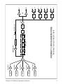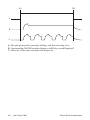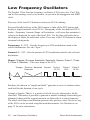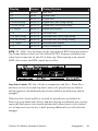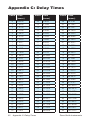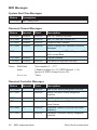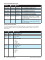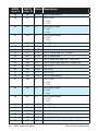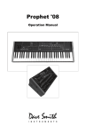
1
Module Operation Manual Module Operation Manual Version 1.0 January 2014 Dave Smith Instruments 1527 Stockton Street, 2nd Floor San Francisco, CA 94133 USA ©2014 Dave Smith Instruments www.davesmithinstruments.com Prophet 12 Operation Manual i This device complies with Part 15 of the FCC Rules. Operation is subject to the following two conditions: (1) This device may not cause harmful interference and (2) this device must accept any interference received, including interference that may cause undesired operation. This Class B digital apparatus meets all requirements of the Canadian Interference-Causing Equipment Regulations. Cet appareil numerique de la classe B respecte toutes les exigences du Reglement sur le materiel brouilleur du Canada. For Technical Support, email: [email protected] ii Dave Smith Instruments Table of Contents Thank You . . . . . . . . . . . . . . . . . . . . . . . . . . . . . . . . . . . . . . . . . . vii Your Prophet 12 Module is Hot!. . . . . . . . . . . . . . . . . . . . . . . . . . ix Overview. . . . . . . . . . . . . . . . . . . . . . . . . . . . . . . . . . . . . . . . . . . . .1 Getting Started. . . . . . . . . . . . . . . . . . . . . . . . . . . . . . . . . . . . . . . . . . . Using the Display and “Soft” Controls. . . . . . . . . . . . . . . . . . . . . . . . . . Using Compare. . . . . . . . . . . . . . . . . . . . . . . . . . . . . . . . . . . . . . . . . . . Saving Programs . . . . . . . . . . . . . . . . . . . . . . . . . . . . . . . . . . . . . . . . . Moving to the Next Level . . . . . . . . . . . . . . . . . . . . . . . . . . . . . . . . . . . 1 2 2 3 3 Connections. . . . . . . . . . . . . . . . . . . . . . . . . . . . . . . . . . . . . . . . . . 6 Global Settings . . . . . . . . . . . . . . . . . . . . . . . . . . . . . . . . . . . . . . . 8 Oscillators . . . . . . . . . . . . . . . . . . . . . . . . . . . . . . . . . . . . . . . . . . 12 Character . . . . . . . . . . . . . . . . . . . . . . . . . . . . . . . . . . . . . . . . . . . 17 Low-Pass Filter . . . . . . . . . . . . . . . . . . . . . . . . . . . . . . . . . . . . . . 18 High-Pass Filter. . . . . . . . . . . . . . . . . . . . . . . . . . . . . . . . . . . . . . 21 Voltage Controlled Amplifier . . . . . . . . . . . . . . . . . . . . . . . . . . . 22 Feedback . . . . . . . . . . . . . . . . . . . . . . . . . . . . . . . . . . . . . . . . . . . 24 Delay. . . . . . . . . . . . . . . . . . . . . . . . . . . . . . . . . . . . . . . . . . . . . . . 25 Reverb and Modulation-Based Effects. . . . . . . . . . . . . . . . . . . . . . . . 27 Low Frequency Oscillators. . . . . . . . . . . . . . . . . . . . . . . . . . . . .28 Auxiliary Envelopes . . . . . . . . . . . . . . . . . . . . . . . . . . . . . . . . . . 31 Modulation. . . . . . . . . . . . . . . . . . . . . . . . . . . . . . . . . . . . . . . . . . 32 Using the Assign Mod Buttons. . . . . . . . . . . . . . . . . . . . . . . . . . . . . . 33 Prophet 12 Operation Manual iii Distortion. . . . . . . . . . . . . . . . . . . . . . . . . . . . . . . . . . . . . . . . . . . 34 Unison . . . . . . . . . . . . . . . . . . . . . . . . . . . . . . . . . . . . . . . . . . . . . 35 Glide. . . . . . . . . . . . . . . . . . . . . . . . . . . . . . . . . . . . . . . . . . . . . . . 36 Hold. . . . . . . . . . . . . . . . . . . . . . . . . . . . . . . . . . . . . . . . . . . . . . . . 37 Arpeggiator . . . . . . . . . . . . . . . . . . . . . . . . . . . . . . . . . . . . . . . . . 38 Master Volume/Voice Volume. . . . . . . . . . . . . . . . . . . . . . . . . . . 42 Pitch and Modulation Wheels. . . . . . . . . . . . . . . . . . . . . . . . . . . 43 Mod Wheel. . . . . . . . . . . . . . . . . . . . . . . . . . . . . . . . . . . . . . . . . . . . . 43 Layers, Split, and Stack . . . . . . . . . . . . . . . . . . . . . . . . . . . . . . . 44 Managing Layers . . . . . . . . . . . . . . . . . . . . . . . . . . . . . . . . . . . . . . . . 44 Multi Mode Operation . . . . . . . . . . . . . . . . . . . . . . . . . . . . . . . . . 46 Using USB . . . . . . . . . . . . . . . . . . . . . . . . . . . . . . . . . . . . . . . . . . 47 Appendix A: Modulation Sources . . . . . . . . . . . . . . . . . . . . . . . 49 Appendix B: Modulation Destinations. . . . . . . . . . . . . . . . . . . . 50 Appendix C: Delay Times. . . . . . . . . . . . . . . . . . . . . . . . . . . . . . 52 MIDI Implementation. . . . . . . . . . . . . . . . . . . . . . . . . . . . . . . . . . 55 MIDI Messages. . . . . . . . . . . . . . . . . . . . . . . . . . . . . . . . . . . . . . . . . . NRPN Messages . . . . . . . . . . . . . . . . . . . . . . . . . . . . . . . . . . . . . . . . Sysex Messages. . . . . . . . . . . . . . . . . . . . . . . . . . . . . . . . . . . . . . . . . Packed Data Format. . . . . . . . . . . . . . . . . . . . . . . . . . . . . . . . . . . . . . 56 61 83 86 Appendix E: Support. . . . . . . . . . . . . . . . . . . . . . . . . . . . . . . . . . 87 Troubleshooting . . . . . . . . . . . . . . . . . . . . . . . . . . . . . . . . . . . . . . . . . 87 Contacting Technical Support. . . . . . . . . . . . . . . . . . . . . . . . . . . . . . . 88 Warranty Repair. . . . . . . . . . . . . . . . . . . . . . . . . . . . . . . . . . . . . . . . . 89 iv Dave Smith Instruments Credits and Acknowledgements For Sound Design: Alessandro Cortini Richard Devine Rory Dow Peter Dyer Robert Henke Tim Koon Kurt Kurasaki Kevin Lamb Jon Lehmkuhl Jamie Lidell Tim Mantle (Psalm37) Drew Neumann Phil Peskett Lorenz Rhode Robert Rich Howard Scarr Matia Simovich James Terris Mitch Thomas Mark Wilcox Taiho Yamada Special thanks also to: Jeff Pence, Robert Rich, and Riley Smith And to the DSI crew: Ashley Bellouin, Bob Coover, Carson Day, Chris Hector, Tony Karavidas, Mark Kono, Andrew McGowan, Joanne McGowan, and Tracy Wadley Prophet 12 Operation Manual v vi Dave Smith Instruments Thank You I’ve been designing synthesizers for 35 years now, starting with the Prophet-5 in 1978. Often times over the years, people have asked which instrument is my favorite. I’ve never been able to answer that question; it’s like picking your favorite child. The Prophet-5 since it was the first, and a breakthrough instrument? The Evolvers with their hybrid analog/digital architecture? The Prophet ’08, as a modern analog poly synth, a full-featured followup 30 years after the Prophet-5? The Prophet VS? Wavestation? The problem is now resolved: the Prophet 12 is my favorite. No question. It sounds different than my other designs, yet it retains the Prophet vibe. There’s something magical about the combination of a digital front end followed with analog filters and electronics per voice. The Prophet 12 has a sound, a soul of its own, unlike any other instrument. I love it! I hope you enjoy playing this instrument as much as we enjoyed designing it. Thanks for the purchase, from the team at DSI! Cheers, Prophet 12 Operation Manual Thank You vii viii Thank You Dave Smith Instruments Your Prophet 12 Module is Hot! Figuratively and literally. Under normal operating conditions, that is not a cause for concern. The Prophet 12 Module packs a lot of DSP power and analog circuitry into a very compact instrument and, as a result, it can generate a fair amount of heat. Since you’re reading the manual, you have probably noticed that the module’s enclosure is well ventilated on both the bottom and rear. Do not obstruct the vents when it’s powered on and avoid placing it in a small enclosed space with little or no air circulation. We also discourage use in direct sunlight under any circumstance, but particularly when the ambient temperature is high. Prophet 12 Operation Manual Your Prophet 12 Module is Hot! ix x Your Prophet 12 Module is Hot! Dave Smith Instruments Overview This is a brief overview of the Prophet 12 module, describing its capabilities and its operation. More in-depth information about specific parameters can be found in the reference section of the manual. However, don’t let a lack of familiarity with either the instrument or sound synthesis prevent you from turning knobs and pressing buttons—that’s what they’re there for! You won’t break anything and you can always get back to where you started, even if you have no idea what you’re doing. Great things can occur with synthesizers when you don’t quite know what to expect, so start twiddling and keep your ears—and mind—open. Getting Started The Prophet 12 module is a twelve-voice, polyphonic synthesizer, which allows up to twelve distinct notes to play simultaneously. We refer to the Prophet 12 as a hybrid synthesizer. That is, it uses a combination of digital and analog audio electronics to generate its sounds, called programs. The Prophet 12 contains 792 programs organized into eight banks of 99. Half the programs are in four Factory banks and the rest are in four User banks. When a Prophet 12 leaves the factory, the User banks are an exact copy of the Factory banks. Program 1 in bank 1 of the User banks is the same as program 1 in bank 1 of the Factory banks, User program 2 is the same as Factory program 2, and so on. All programs in either the Factory or User banks can be edited using the front panel controls, but the edits cannot be saved to the Factory banks, only the User banks. The Factory banks are read-only, permanent. Choosing programs is simple. Use the Bank Select knob to choose User banks (U1, U2, U3, U4), or Factory banks (F1, F2, F3, F4), and then use the Program Select knob to select program number, 01 through 99. While auditioning programs, it should become obvious that some programs are split—two different sounds can be played from different zones of the keyboard— and some are stacked—one sound is layered on another. The Prophet 12 is bi-timbral. That is, it can play two different sounds simultaneously and each of those sounds can be routed to its own stereo outputs, if desired. Each of the Prophet 12’s program memory locations is capable of saving and recalling two different programmed sounds, one in layer A and one in layer B. Layers are used to facilitate split and stacked programs. Prophet 12 Module Operation Manual Overview 1 A split program maps the layer A sound to a key zone on the left side of the split point and the layer B sound to the right. Six voices are allocated to each key zone. A stacked program maps both layers A and B to the entire keyboard, with six voices allocated to each layer. So, when Stack A + B is on, the maximum polyphony is six. (At least two voices play with each keystroke.) The voice activity LEDs indicate how the voices are being used. If Split A | B or Stack A + B are not on, the layer B sound can still be accessed and edited by pressing Edit Layer B. This also provides a shortcut to switch quickly between two sounds without actually changing programs. Using the Display and “Soft” Controls The Prophet 12’s parameters are all accessible by pressing the associated front panel switch, and then editing the parameters via the OLED display. It’s a quick and easy method of getting to the control you want without having to drill down though endless menus. Synth parameters are selected and tweaked using the four soft knobs and soft keys located above and below the display. The soft knobs are detented encoders and are great for dialing in specific values. The “Soft Knobs” The “Soft Keys” Using Compare At any point while editing a program, turn on Compare to hear the saved, unedited program. Or, to revert to the saved program, just reload it by momentarily selecting another bank using the Bank Select knob. When you switch back to the original bank, the unedited program will be restored. 2 Overview Dave Smith Instruments Saving Programs Saving an edited program is easy. As mentioned previously, you can compare the edited program to the saved program at any time using Compare. Once you’re ready to commit, press Write. Press the flashing Write button again to save. A. Write Bank (soft knob 1)—Choose the User Bank (1 through 4) to which the program will be saved. B. Write Program (soft knob 2)—Choose the program (1 through 99) to which the program will be saved. C. Select Char (soft knob 3)—Highlight a character in the current layer’s name. D. Edit Char (soft knob 4)—Choose a character. E. Copy Name A > B (soft key 1)—Copy the layer A name to layer B. F. Insert Char (soft key 2)—Insert a character before the selected character. G. Delete Char (soft key 3)—Delete the selected character. H. Select A/B (soft key 4)—Switch between the layer A and layer B name. Saving a program overwrites a previously saved program. While Write is blinking, Compare lets you “audition” the saved program in the bank and program location you have selected, However, Write is disabled when Compare is On. Moving to the Next Level This overview just covers basic operation. The Prophet 12 is a deep instrument filled with possibility and playing it is a lot more compelling than reading a manual. But we would like to point you in the direction of a few things that will help you tailor the instrument to your needs. In particular, check out the Global Settings section of the manual. Read about Pot Modes and determine which works best for you. You’ll also find information about MIDI setup to Prophet 12 Module Operation Manual Overview 3 more effectively integrate the Prophet 12 into your rig, as well as information about using a footswitch and expression pedals. Also, look for the tips and notes scattered throughout the manual to gain a better working knowledge of the instrument. 4 Overview Dave Smith Instruments Prophet 12 Module Operation Manual 5 SUB OSC OSC 4 OSC 3 OSC 2 OSC 1 SUB OSC LEVEL OSC 4 LEVEL OSC 3 LEVEL OSC 2 LEVEL OSC 1 LEVEL OSC MIX CHARACTER GIRTH DRIVE HACK LPF HPF FEEDBACK LOOP Modulation routing omitted for clarity AIR FDBK TUNE PROPHET 12 VOICE ARCHITECTURE DECI FEEDBACK LEVEL VCA PAN DELAY 3 PAN PAN DELAY 2 DELAY 4 PAN DELAY 1 PAN R L R L R L R L R L Connections AC Power Inlet—Accepts 13.5VDC at 1400mA from the supplied external power supply. The tip of the plug is positive (body is ground). USB Sustain Pedal 1 Pedal 2 MIDI In MIDI Out MIDI Thru USB—For bidirectional MIDI communication with a computer. The Prophet 12 is a Class Compliant USB device and does not require additional drivers when used with Mac OS or Windows. The Prophet 12 transmits and receives data via USB, but does not transmit audio. Note: MIDI In and USB should not be used at the same time, as overlap- ping messages from different sources may cause the Prophet 12 to respond unpredictably. MIDI Out and USB can be used at the same time and transmit the same data. See Using USB on page 47 for more information. Sustain—Accepts a momentary, normally open or normally closed footswitch to control sustain or to turn the arpeggiator on and off. See “Sustain Footswitch” under Global Settings on page 10 for more information. Pedal 1 and Pedal 2—Accept a standard expression pedal that has a variable resistor on a TRS (tip-ring-sleeve) ¼″ phone plug. For more information, see “Pedal 1 Function” and “Pedal 2 Function” in Global Settings on page 10. MIDI In, Out, and Thru—Standard 5-pin MIDI DIN connectors. 6 Connections Dave Smith Instruments 15VDC, 1 Main/A Outputs and B Outputs—Unbalanced, ¼″ audio outputs. The Main outputs are a mix of a program’s A and B layers. When plugs are inserted into the B outputs, only layer A is available from the Main outputs and layer B is routed to the B outputs. See Layers, Split, and Stack on page 44 for more information. B Outputs MIDI Thru 15VDC, 1400 mA On / Off Right Left Main / A Outputs Right Left Headphones The Prophet 12 sounds great in stereo, but can be switched to mono. See “Mono/ Stereo” in Global Settings on page 9. Power Switch—Turns the Prophet 12 On of Off. Headphones—A ¼″ stereo headphone jack. Prophet 12 Module Operation Manual Connections 7 Global Settings Press Global to set those parameters, such as Master Tune and MIDI Channel, which affect all programs globally. 1. Master Coarse Tune: -12…+12—Master Transpose control, 0 is centered. Steps in semitones as much as one octave up (+12) or down (-12). 2. Master Fine Tune: -50…+50—Master Fine Tune control; 0 centered. Steps in cents as much as a quarter-tone up (+50) or down (-50). 3. MIDI Channel: All, 1…16—Selects which MIDI channel to send and receive data, 1 to 16. All receives on all 16 channels. 4. MIDI Multi Mode: Off, On—Allows the A & B layers to be controlled by separate MIDI channels. When On, the MIDI channel for layer B will be channel (A+1) and shown in parenthesis, i.e. 1(B:2) in the MIDI channel display (above). 5. MIDI Clock Mode: See table—Sets the Prophet 12’s ability to send and receive MIDI clock messages. Display MIDI Clock Setting Off Master Slave Slave Thru MIDI Clock is neither sent nor received. MIDI Clock is sent, but not received. MIDI Clock is received, but not sent. MIDI Clock is received and passed to MIDI Out. Note: In Slave and Slave Thru modes, if no MIDI clock is present at the selected input, the arpeggiator will not function. 6. MIDI Clock Cable: MIDI Port, USB—Sets the port, MIDI or USB, by which MIDI clocks are received. 7. MIDI Param Send: Off, CC NRPN—Changes to the values of front panel controls are transmitted via MIDI as Non-registered Parameter Number (NRPN) controllers or as Continuous Controllers (CC). Transmission of parameters can also be turned off. See MIDI Implementation on page 55 for details. Note: NRPNs are the preferred method of parameter transmission, since they cover the complete range of all parameters, while CCs are limited to a range of 128. 8 Global Settings Dave Smith Instruments 8. MIDI Param Receive: Off, CC NRPN—Sets the method by which parameter changes are received via MIDI. As with transmission, NRPNs are the preferred method. 9. MIDI Control Enable: Off, On—When On, the synth will respond to MIDI controllers, including Pitch Wheel, Mod Wheel, Pedal, Breath, Volume, and Expression. 10. MIDI Sysex Enable: Off, On—When On, the synth will respond to received MIDI SysEx messages, and will transmit them, when prompted, to the MIDI Out. See Sysex Messages on page 83 for details. 11. MIDI Sysex Cable: None, MIDI Port, USB—Sets the port, MIDI or USB, by which System Exclusive data will be transmitted and received. 12. MIDI Out Select: Off, MIDI, USB, MIDI+USB—Sets the port by which MIDI data will be transmitted. 13. Local Control: Off, On—When on (the default), the front panel controls directly affect the Prophet 12. When off, the controls are transmitted via MIDI but do not directly affect the “local” synth (that is, the Prophet 12). This is primarily useful for avoiding MIDI data loops that can occur with some external sequencers. 14. Mono/Stereo: Stereo, Mono—The Prophet 12 defaults to stereo opera- tion. When set to Mono, this parameter defeats all pan settings and modulation, effectively making each of the outputs a mono output. 15. Pot Mode: Relative, Passthru, Jump—The rotary controls on the Prophet 12’s front panel are a mixture of “endless” rotary encoders and potentiometers or “pots.” The pots are identifiable by their lined knobs and the fact that they have about 300° of travel. There are three pot modes to determine how the synth reacts when the programmable parameters are edited. (Master volume is not programmable, so these modes don’t apply.) When set to Relative, changes are relative to the stored setting. In Relative mode, the full value range is not available until either the minimum or maximum value and the respective lower or upper limit of the pot’s travel is reached. Prophet 12 Module Operation Manual Global Settings 9 For example, the Resonance parameter has a value range of 0 to 127. Let’s say the physical position of the Resonance pot is the equivalent of a value of 100. If you switch to a program that has a stored Resonance setting of 63 and turn the pot all the way up, it will only go to 90. To get to the maximum value of 127, you first have to turn down until the value is at the other extreme and the pot is at the limit of its travel (in this case, 0 and fully counter-clockwise, respectively). In Passthru mode, turning the pot has no effect until after the edited value equals the preset value (that is, until the edited value “passes through” the stored value). Jump mode uses an absolute value based upon the position of the pot when edited: turn a pot and the value jumps immediately from the stored value to the edited value. 16. Sustain Footswitch: Normally Open, Normally Closed—There are two types of momentary footswitches, normally open and normally closed. Either type can be used with the Prophet 12’s Sustain switch input. Not sure which type you have? If the footswitch’s behavior is the opposite of what’s expected—that is, down is off and up is on—changing this setting will correct that. 17. Sustain Pedal Function: Sustain, Arp On/Off—The footswitch can be used for sustain or to turn arpeggiator hold on and off. 18. Pedal 1 Function: Breath Control, Foot Controller, Expression, Master Volume, Lowpass Filter: Full Range, Lowpass Filter: Half Range—Sets the function/destination for the Pedal 1 input. An expression pedal can be routed to any destination using the modulation matrix. See Modulation on page 32 for more information. 19. Pedal 2 Function: Breath Control, Foot Controller, Expression, Master Volume, Lowpass Filter: Full Range, Lowpass Filter: Half Range—Sets the function/destination for the Pedal 2 input. . An expression pedal can be routed to any destination using the modulation matrix. See Modulation on page 32 for more information. 20. Basic Patch—Press Write Now (soft key 1) to load a basic, template program into the edit buffer. Use Write to permanently save any changes to memory. 10 Global Settings Dave Smith Instruments 21. Autotune Filters—Press Start Tuning (soft key 1) and follow the onscreen instructions to tune the low- and high-pass filters. Note: The filters are calibrated at the factory and under normal circum- stances should not require re-calibration or re-tuning. 22. Reset Globals—Sets the global parameters to the factory default settings. 23. Dump Current Program—Transmits the current program in SysEx format via the selected MIDI port. (See “9. MIDI Sysex Cable.”) Dumped programs will load back into the same bank and program location in memory when received by the Prophet 12 via MIDI. 24. Dump Current Bank—Transmits the current bank in SysEx format via the selected MIDI port. (See “9. MIDI Sysex Cable.”) Dumped banks will load back into the same bank location in memory when received by the Prophet 12 via MIDI. 25. Dump All User Banks—Transmits all four User Banks in SysEx format via the selected MIDI port. (See “9. MIDI Sysex Cable.”) Dumped banks will load back into the same bank location in memory when received by the Prophet 12 via MIDI. Prophet 12 Module Operation Manual Global Settings 11 Oscillators The Prophet 12 has four oscillators for each of its twelve voices. The oscillators are capable of generating the “classic” analog wave shapes—sine, triangle, sawtooth, square—as well as more complex shapes and different types of noise. Use the four oscillator buttons to select an oscillator for editing. The arrows that connect the oscillator buttons is a graphic representation showing which oscillator affects another when the Sync, FM (frequency modulation), or AM (amplitude modulation) parameters are used. Oscillator 2 affects oscillator 1, oscillator 3 affects oscillator 2, and so on. For information about what the Sync, FM, and AM parameters do, see the relevant items later in this section. Tip: To edit a parameter on all oscillators simultaneously, press and briefly hold any of the oscillator select buttons until all of them are lit. Select the desired parameter using Prev and Next Param (Soft keys 2 & 3). Press and hold, Hold: Edit All (Soft key 1) while adjusting one of the soft knobs. Or use the soft knobs to edit the same parameter for each oscillator individually. Press any oscillator button to exit. Shape/Noise: Off, Sawtooth, Pulse, Triangle, Sine, Tines, Mellow, Church, Muted, Nasal, Boing, Gothic, Ahhh, Shrill, Ohhhh, Buzzzz, Meh, Red Noise, White Noise, Violet Noise—Used to select the wave shape or type of noise generated by the selected oscillator. Wave shapes include four typical analog synthesizer waves as well as twelve more complex wavetable sounds. There are also three types of noise: red, white, and violet. Shape Mod/Pulse Width: -64…0…63—Causes the wave shape to be altered. How it changes depends upon the selected shape. A setting of 0 is the default, unaffected shape. When Sawtooth is the selected shape, Shape Mod/Pulse Width controls the symmetry of the wave, similar to pulse width on the Pulse wave creating the rich sound of two sawtooth oscillators. 12 Oscillators Dave Smith Instruments Shape Mod/Pulse Width affects the pulse width or duty cycle of the Pulse wave. -64 0 Pulse Width 63 When Triangle is the selected shape, the width of the wave is changed, similar to Pulse and Sawtooth, adding harmonics and getting more thin sounding when turned in either direction from 0. With Sine as the selected shape, values less than 0 gradually add another sine an octave higher than the base pitch. Values greater than 0 cause the sine wave to gradually be clipped, adding harmonics and sounding somewhat distorted. For the 12 wavetable shapes, Shape Mod/Pulse Width crossfades between the selected shape and the Wave Left and Wave Right selections. Let’s say, for example, that the selected wave shape is Mellow, Wave Left is set to Tines, and Wave Right is set to Nasal. A Shape Mod/Pulse Width setting of -64 will be the Tines wave, 0 will be Mellow, and +63 will be Nasal. Values between -64 and 0 will be a mix of Tines and Mellow; values between 0 and +63 will be a mix of Mellow and Nasal. An extremely broad variety of hybrid wave shapes can be created by mixing two of the wavetable shapes. And, of course, Shape Mod/Pulse Width is a modulation destination, so an LFO or other modulation source can be routed to it. Note that the algorithm used to mix the waves is not simply a mix. If all three are set to the same wave, there will still be a noticeable difference in the sound as Shape Mod changes. Shape Mod/Pulse Width also works when noise is the selected shape. With a Shape Mod value of 0, the displayed noise type is what is heard. Values less than 0 gradually cause it to change to a second noise type. Values greater than 64 cause it to change to a third noise type. The left and right noise sources are fixed. Try it. It’s much easier to hear than to explain! The display also provides a visual indication of the change. Wave Left, Wave Right—Sets the wavetable shapes used in conjunction with the Shape Mod/Pulse Width parameter. Wave Left and Wave Right are only active when one of the twelve wavetables is selected as the primary oscillator shape. See “Shape Mod/Pulse Width” for more information. Prophet 12 Module Operation Manual Oscillators 13 Pitch: C 0…C 10—Sets the base oscillator frequency over a 10-octave range, from 8 Hz to 8kHz, stepping in semitones. C3 is middle C, the first octave is 0 (C0, C#0, etc.), the second octave is 1 (C1, C#1, etc.), and so on. Note: The global Master Tune settings affect the pitch of all oscillators. See Global Settings on page 8 for more information. Fine: -50…+50—Fine tune control with a range of a quartertone up or down. Zero is centered. Steps are in cents (50 cents = 1/2 semitone). Key Follow: Off, On—When Key Follow is on, the oscillator tracks the note data received via MIDI. When off, the oscillator plays at its base frequency setting, though the pitch may be affected by modulation from other sources. Wave Reset: Off, On—When Wave Reset is off, the Prophet 12’s oscillators are free running, which is typically how analog synths behave. That is, the oscillators are running whether a note is being gated on or not. When the amplifier envelope is set for a fast attack, this can cause a soft, but detectable, pop or click at the beginning of a note because the note might be gated on at a point in the wave’s cycle other than a zero crossing. The first cycle to play might be truncated. For some sounds, like monophonic basses, this may actually be desirable. It adds a bit of randomness to the attack that can make it sound, for lack of a better word, more organic. When Wave Reset is on, the wave is always reset to zero—the start of its cycle—when a note is gated on. Sync: Off, On—Turns oscillator hard sync on. Sync utilizes pairs of oscillators to force one oscillator (the slave) to restart its cycle every time the other oscillator (the master) starts a cycle. This provides a way to create more complex, harmonically rich shapes from simple waveforms. Oscillator 1 Oscillator 2 Oscillator 1 synced to Oscillator 2 14 Oscillators Dave Smith Instruments The arrows between the oscillator select buttons show how the oscillators are paired, as does the following table. Master Slave controls Osc Osc 2 1 3 2 4 1 3 4 The effect of Sync is much more easily heard than explained. Here’s a simple example of how to use Sync. 1. Load the Basic Patch from the Global menu. Oscillator 1 and 2 Shape is set to sawtooth and oscillators 3 and 4 are off. 2. Turn oscillator 2 Output Level to 0. Only oscillator 1 should be audible. 3. Turn oscillator 1 Sync on. 4. Now turn oscillator 1 Pitch while playing the keyboard. The harmonic content changes, but not the fundamental pitch. Now do the same thing while turning oscillator 2 Pitch. (Remember: only oscillator 1 should actually be audible.) The fundamental pitch changes, but the harmonic content is relatively consistent. Oscillator 2 is the master and oscillator 1 is the slave. Tip: Use glide, an envelope generator, an LFO, the mod wheel, or other modulation source to sweep the pitch of a slave oscillator. Of course, each of the four oscillators can be synced, so it’s possible to have two pairs of synced oscillators or to sync oscillators in series (an oscillator synced to a synced oscillator, synced to a synced oscillator…). Note: The Oscillator 1 Sub Octave does not sync to oscillator 2. To sync oscillator 1 and have a sub octave that plays in tune with oscillator 2, use one of the other oscillators as a sub. Output Level: 0…127—Sets the output level for each of the oscillators. Note: When using three or four oscillators, it may be necessary to reduce the levels of each to avoid clipping. Prophet 12 Module Operation Manual Oscillators 15 Frequency Modulation (FM): 0…127—Allows one oscillator—called the modulator, for the purposes of FM synthesis—to modulate the frequency of another oscillator—called the carrier. The arrows between the oscillator select buttons show the modulator/carrier relationship between the oscillators, as does the following table. Carrier Modulator Oscillator 1 Oscillator 2 Oscillator 3 Oscillator 4 Oscillator 2 Oscillator 3 Oscillator 4 Oscillator 1 Turning up FM for oscillator 1 causes it to be modulated by oscillator 2, turning up FM for oscillator 2 causes it to be modulated by oscillator 3, and so on. Note: The indicated order of modulation is really just a handy shortcut. In fact, you can route any oscillator to another using the modulation matrix. See Modulation on page 32 for more information. Amplitude Modulation (AM): 0…127—As with FM, AM uses the oscillators as carrier/modulator pairs. But with AM, the modulator modulates the carrier’s amplitude, not its frequency. As with FM, any oscillator routing combination can be configured using the modulation matrix. Glide Amount: 0...127—Sets the oscillator glide (portamento) amount. Glide can be set independently for each oscillator. Low values are shorter/faster. The Glide switch must be on to hear the effect of Glide Amount. For a detailed explanation, see Glide on page 36. Tip: To set Glide Amount for all oscillators simultaneously, press and briefly hold any of the oscillator select buttons until all of them are lit. Repeatedly press Prev and Next Param (Soft keys 2 & 3) until Glide is displayed. Press and hold, Hold: Edit All (Soft key 1) while adjusting one of the soft knobs. Press any oscillator button to exit. Slop: 0…127—Adds random detuning to the oscillator to emulate the tuning instability of voltage controlled analog oscillators, from subtle, barely perceptible amounts to wildly out of tune. Oscillator 1 Sub Octave: 0…127—Controls the level of a sine wave oscilla- tor pitched one octave below oscillator 1. 16 Oscillators Dave Smith Instruments Character The Character controls affect the sonic character of the mixed output of the oscillators. The effect may or may not be subtle and may be dependent upon the frequency and harmonic content of the audio being processed. For example, Girth boosts and enhances low frequencies, so the effect upon high frequency content is minimal. Girth: 0…127—A low shelf filter to boost low frequencies, with some extra harmonic modification at higher settings. Air: 0…127— A high shelf filter to boost high frequencies, with some extra harmonic modification at higher settings. Hack: 0…127—Reduces the bit depth of the mixed output from the oscillators. Decimation: 0…127—Reduces the sample rate of the mixed output from the oscillators. Drive: 0…127— Emulates tape saturation. Prophet 12 Module Operation Manual Character 17 Low-Pass Filter The Prophet 12 features one analog resonant low-pass filter per voice. The filter is switchable between 2- and 4-pole modes and has a dedicated five-stage (delay/ attack/decay/sustain/release) envelope generator, capable of looping the delay, attack, and decay segments. There are also controls for modulating the filter cutoff with the keyboard and envelope amount with keyboard velocity. 4-Pole—Selects the filter configuration. When lighted, the filter is in 4-pole mode. A 4-pole, low-pass filter rolls off frequencies above the cutoff frequency at a slope of 24dB per octave. When the button is off, the filter is in 2-pole mode and has a slope of 12dB per octave and a more gradual roll-off of the higher frequencies. Frequencies below the cutoff pass through unaffected, hence the name “low-pass.” Frequency: 0...164—Sets the low-pass filter’s cutoff frequency over a range of more than 13 octaves, stepping in semitones. The cutoff transitions smoothly across the values when the frequency is swept. Resonance: 0...127—Emphasizes a narrow band of frequencies around the cutoff frequency. In 4-pole mode, high levels of resonance can cause the filter to self oscillate. In 2-pole mode, resonance is much more subtle and self-oscillation does not occur. Key Amount: 0...127—Sets the amount of modulation from the note data received via MIDI to Frequency (the filter’s cutoff frequency). A setting of 64 will step the filter in semitone increments for each note, 32 would be quartertones, and so on. VelocityEnvelope Amount: 0...127—Enables keyboard velocity to modu- late the filter Envelope Amount. Envelope Amount: -127...127—Sets the amount of modulation from the low-pass filter envelope to the low-pass filter frequency. The modulation amount can be positive or negative, allowing for inverted envelope control. Note: The low-pass frequency setting may limit the effect of the envelope on the filter. For example, if Frequency is all the way up, a positive envelope amount will have no effect on the filter. Delay: 0...127—Sets a delay between the time the envelope is gated on and 18 Low-Pass Filter Dave Smith Instruments when the Attack segment actually begins. Attack: 0...127—Sets the attack time of the envelope. Decay: 0...127—Sets the decay time of the envelope. Sustain: 0...127—Sets the sustain level of the envelope. Amplitude Release Sustain Decay Attack Delay Release: 0...127—Sets the release time of the envelope. Time DADSR Envelope Repeat: Off, On—When on, the Delay, Attack, and Decay segments of the envelope repeat. Sustain still affects the level at which the Decay segment ends, but—instead of sustaining at a fixed level while a note is gated on—Delay, Attack, and Decay loop until the note is turned off. The Release segment begins when the note is gated off, just as it does when Repeat is off. See the illustration on the following page. Prophet 12 Module Operation Manual Low-Pass Filter 19 On Off A B C A: The gate generated by pressing, holding, and then releasing a key. B: Corresponding DADSR envelope behavior with Delay on and Repeat off. C: Behavior of the same envelope with Repeat on. 20 Low-Pass Filter Dave Smith Instruments High-Pass Filter After each voice’s low-pass filter, the signal passes through a 2-pole, resonant analog high-pass filter. There is also a control for modulating the filter cutoff with the keyboard. Frequency: 0...127—Sets the high-pass filter’s cutoff frequency. Frequencies below the cutoff are attenuated at a slope of 12 dB per octave. Frequencies above the cutoff pass through the filter unaffected, hence the name “high-pass.” Resonance: 0...127—Emphasizes a narrow band of frequencies around the cutoff frequency. Normally, the high-pass filter does not self oscillate at the maximum resonance setting. However, it may be driven into self-oscillation by routing DC modulation to resonance to push it beyond what can be achieved by the Resonance control alone. Be aware, though, that the signal level of the self-oscillation is significantly higher than normal, and will likely cause severe clipping, especially as more voices are played. That can be mitigated by turning down the voltage controlled amplifier envelope amount and, if used, the VCA VelocityAmount. Key Amount: 0...127—Sets the amount of modulation from the note data received via MIDI to Frequency (the filter’s cutoff frequency). A setting of 64 will step the filter in semitone increments for each note, 32 would be quartertones, and so on. Note: The high-pass filter does not have a dedicated envelope like the low- pass does. However, auxiliary envelopes 3 and 4 can be routed directly to the high-pass filter, and any of the envelopes can be used to modulate the high-pass using the modulation matrix. See Modulation on page 32 for more information. Prophet 12 Module Operation Manual High-Pass Filter 21 Voltage Controlled Amplifier After passing through the filter stages, the signal goes into an analog voltage controlled amplifier or VCA. The VCA has a dedicated, five-stage envelope generator. (See Low-Pass Filter on page 18 for an illustrated example of an envelope generator.) There is a control for modulating the envelope amount using keyboard velocity, as well as a control for left/right spread of the voices in the stereo field. Envelope Amount: 0...127—Sets the amount of modulation from the amplifier envelope to the VCA. See the following item, VelocityEnvelope Amount, for information about setting a program’s velocity sensitivity. VelocityEnvelope Amount: 0...127—It’s very easy to misunderstand what this control does. It enables keyboard velocity to modulate the VCA Envelope Amount. What it does not do is use keyboard velocity to directly control the VCA. To create a program in which velocity controls the VCA, turn VCA Envelope Amount down and turn VelocityEnvelope Amount up. To achieve the best results, it may be necessary to set an initial level using Envelope Amount. Just remember that once Envelope Amount is set to the maximum, no modulation from velocity—or any other source—will cause it to go higher than that. Program Volume: 0...127— Sets the volume of the current program to match volumes between programs. Note: There is enough gain in the synth voice that, with some settings, some mild clipping distortion may be heard. If this happens, try lowering the Program Volume, and/or the VCA Envelope Amount (or VCA Velocity Env Amount). Pan Spread: 0...127—Pans the audio in the stereo field individually per voice. Set to 0, all voices are panned to the center. As Pan Spread is turned up, the audio in each voice is gradually moved away from the center by different amounts. Every other voice goes in a different direction, left or right. This creates a broader stereo field while playing. Any modulation to Pan will individually move each voice from its position as set by Pan Spread. 22 Voltage Controlled Amplifier Dave Smith Instruments Delay: 0...127—Sets a delay between the time the envelope is gated on and when the Attack segment actually begins. Attack: 0...127—Sets the attack time of the envelope. Decay: 0...127—Sets the decay time of the envelope. Sustain: 0...127—Sets the sustain level of the envelope. Release: 0...127—Sets the release time of the envelope. Repeat: Off, On—When on, the Delay, Attack, and Decay segments of the envelope repeat. Sustain still affects the level at which the Decay segment ends, but—instead of sustaining at a fixed level while a note is gated on—Delay, Attack, and Decay loop until the note is turned off. The Release segment begins when the note is gated off, just as it does when Repeat is off. For an illustrated example, see Low-Pass Filter on page 18. Prophet 12 Module Operation Manual Voltage Controlled Amplifier 23 Feedback The analog output of the VCA is input to a tuned delay, whose output is mixed with the oscillators and input to the character effects. Each voice has its own tuned delay. Feedback Amount: -127…0…127—Sets the level of feedback. As the level goes up, the feedback will eventually oscillate at the set Tuning. Medium levels of feedback add depth and movement to the sound. Negative values invert the signal producing different results than positive values. Note: Be careful when using feedback and filter settings with high reso- nance. It can get loud quickly! Tuning: 0…48—Sets the base frequency of the feedback loop. It steps in semitones from C0 to C4 for a four-octave range. The frequency always tracks the keyboard. The exact frequency is influenced by other factors, such as the filter frequency and number of poles, which can drive it slightly sharp or flat. 24 Feedback Dave Smith Instruments Delay The Prophet 12 has a stereo, four-tap digital delay per voice. It can be used for simple delays or, in conjunction with modulation and short delay times, flanging and chorus effects. Simple reverbs can be built using different delay times and settings on the level and feedback of all four delays. A lowpass or highpass filter in the feedback path allows you to simulate analog tape echoes or unnatural effects. In addition, the delay time can be synced to the arpeggiator and various modulation sources can be routed to delay panning. Number of Echoes Feedback Time between Echoes DELAY Mix w/original Echo Tone Color LP/HP Filter Stereo Position L Pan R Digital Delay (x4) The outputs of the delay are mixed back in with the synth’s left and right channels, so the primary audio path from the filters forward is still entirely analog. Delay Time: 0...255—Sets the delay time for the selected tap, from a minimum of 0.9556 milliseconds and a maximum of 1 second. For a complete list of the available delay times, see Delay Times on page 52. Amount: 0...127—Sets the level of the delayed signal. When set to 0, the delay is essentially off. Feedback: 0...127—Sets the amount of feedback from the selected delay tap to the input of the delay. Sync: Off, On—Sets the delay time to a subdivision or multiple of the BPM setting. This allows the delay to be synced to the arpeggiator and MIDI clock. The sync settings are all based upon one beat equals one quarter note. Prophet 12 Module Operation Manual Delay 25 When Sync is on, Delay Time displays the following values. Displayed Value Delay Time 64th 32nd 32nd Dot 16th 16th Dot 8th 8th Dot Qrtr Qrtr Dot Half Half Dot Whole 1/16 of 1 beat 1/8 of 1 beat 3/16 of 1 beat 1/4 of 1 beat 3/8 of 1 beat 1/2 of 1 beat 3/4 of 1 beat 1 beat 1 1/2 beat 2 beats 3 beats 4 beats Note: The maximum delay time is 1 second. The combination of longer synced delay times with slower tempos can result in delay times that would be greater than 1 second. When that happens, the delay time is divided by 2 until it no longer exceeds the 1 second limit. For example, if the BPM is set to 60 and Delay Time is set to Half, the expected delay time would be 2 seconds. The actual delay time will be 1 second (2 seconds divided by 2). LP/HP Freq: 0…127—Sets the cutoff frequency of the lowpass or highpass filter in the output/feedback path. A lowpass setting of 127 results in no filtering. The highpass filter works just the opposite, where a setting of 127 equals maximum filtering. Mode: Lowpass, Highpass—Selects either a lowpass or highpass filter in the output/feedback path. Use the lowpass filter to create natural sounding echoes and analog tape echo effects. The highpass filter can create interesting flange effects and unnatural sounding echoes. Delay Pan: 0…127—Allows you to pan the output of the delay anywhere in the stereo field. This is very useful in creating a rich stereo image as well as for ping-pong effects. Delay Pan is also a modulation destination. That is, the stereo pan position of the delayed signal can be modulated using an LFO or any mod source in the modulation matrix. 26 Delay Dave Smith Instruments Reverb and Modulation-Based Effects A reverb is effectively multiple delays of a source signal as it moves through a space and bounces off of various surfaces. Convincing small to medium sized rooms, spring, and plate reverb effects can be simulated using the four delay paths, feedback paths, and amounts. Try setting each of the delay times to different time settings between 30 and 70. Set the amounts and feedbacks to different values and listen to how the sound changes. Altering the values of the above parameters will “sculpt” the sound of the reverberation. The delay time can be modulated to produce flanging and chorus effects. The main difference between the two is that flanging uses feedback and chorus does not, and chorus typically uses a longer delay time (though, with modulation, the range of delay times for each effect may actually overlap a bit). For flanging, a Time value of 31 (4.8157 milliseconds) or less is a good place to start. Use a triangle wave LFO to modulate the delay time, being careful to keep the LFO Amount low so that it doesn’t drive the delay time to zero and “flatten out” the triangle at one extreme. It will be fairly obvious when that happens. For chorus, start with a value around 53 (17.164 milliseconds). For ping-pong effects, use a square LFO routed to Delay Pan. The Delay Pan parameter sets the initial pan position. Both the LFO and the Delay must have Sync on, and the LFO should also have Wave Reset on, to keep everything in sync. Prophet 12 Module Operation Manual Delay 27 Low Frequency Oscillators The Prophet 12 has four low frequency oscillators (LFOs) per voice. The LFOs can be free-running, reset by keystrokes, or synced to the arpeggiator and MIDI clock. Press any of the four LFO buttons to choose an LFO for editing. Press and briefly hold any of the LFO buttons to light all the LFO buttons and display a single parameter for all LFOs. Turning any of the four dedicated LFO knobs—Frequency, Amount, Shape, or Destination—will cause that parameter’s value to be displayed for each of the four LFOs. Use the four soft knobs above the display to adjust the individual values. Press any of the LFO buttons to return to normal editing mode. Frequency: 0...127—Sets the frequency of LFO modulation routed to the selected destination. See also “Sync.” Amount: 0...127—Sets the amount of LFO modulation routed to the selected destination. Shape: Triangle, Reverse Sawtooth, Sawtooth, Square, Pulse 1, Pulse 2, Pulse 3, Random—The wave shape of the LFO. Triangle Reverse Sawtooth Square Sawtooth Pulse 1 37.5% Pulse 2 25% Pulse 3 12.5% 0 Random, also known as “sample and hold,” generates a series of random values, each held for the duration of one cycle. Triangle is bipolar. That is, it is positive for half its cycle and negative for the other half. That makes it possible to generate a natural-sounding vibrato that goes alternately sharp and flat in equal amounts on either side of a center frequency. The other wave shapes and Random generate only positive values. However, any of the LFOs can be inverted using the modulation matrix. See Modulation on page 32 for more information. 28 Low Frequency Oscillators Dave Smith Instruments Destination—The parameter being modulated by the LFO. See Modulation Destinations on page 50 for a list of possible destinations. Sync: Off, On—When on, Frequency displays note values that sync precisely with the arpeggiator and delay. Displayed Value Cycle Duration 32nd Trip 32nd 16th Trip 16th 8th Trip 8th Qrtr Trip 1 Qrtr Qrtr Dot 1/2 Note 3 Qrtr 4 Qrtr 6 Qrtr 8 Qrtr 16 Qrtr 32 Qrtr 1/12 of 1 beat 1/8 of 1 beat 1/6 of 1 beat 1/4 of 1 beat 1/3 of 1 beat 1/2 of 1 beat 1 1/3 beats 1 beat 1 1/2 beats 2 beats 3 beats 4 beats 6 beats 8 beats 16 beats 32 beats Phase Offset in Degrees 0° 180° 360° 90° 270° Phase: 0...127—Used in conjunction with Wave Reset, Phase sets the initial phase, from 0 to 360 degrees, at which the LFO wave shape starts when keyed on. Each step represents 2.8125°, so a value of 32 equals 90°, 64 equals 180°, and so on. Note: For Phase to have any noticeable effect, Wave Reset must also be turned on for that LFO. If the LFO is free-running—that is, Wave Reset is off—there is no fixed start point from which the phase can be offset. Slew Rate: 0...127—Slew rate is defined as the maximum possible rate of change of a signal. The effect of the Slew Rate control is most obviously heard on Prophet 12 Module Operation Manual 0 32 64 96 127 Phase Parameter Value Low Frequency Oscillators 29 Pulse and Random, shapes that normally change state virtually instantaneously. As Slew Rate increases, those changes are drawn out, elongated, and the result is a sort of smoothing effect. Wave Reset: Off, On—When off, the LFO is free running. When on, the LFO is re-started each time a new note is played. Wave Reset is set independently for each LFO. Note: Use Phase to offset the start point when Wave Reset is on. 30 Low Frequency Oscillators Dave Smith Instruments Auxiliary Envelopes The Prophet 12 has four, five-stage envelope generators. Two of them are dedicated to the low-pass filter and VCA, but the other two can be routed to any of the modulation destinations. Note: Actually, any of the envelopes can be routed to any destination—or multiple destinations—using the modulation matrix. See Modulation on page 32 for more information. See Low-Pass Filter on page 18 for an illustrated example of an envelope generator. Destination—The parameter being modulated by the envelope. See Modulation Destinations on page 50 for a list of possible destinations. Envelope Amount: -127...127—Sets the amount of modulation from the envelope to the chosen destination. The modulation amount can be positive or negative, allowing for inverted envelope control. VelocityEnvelope Amount: 0...127—Enables keyboard velocity to modu- late the Envelope Amount. Delay: 0...127—Sets a delay between the time the envelope is gated on and when the Attack portion actually begins. Attack: 0...127—Sets the attack time of the envelope. Decay: 0...127—Sets the decay time of the envelope. Sustain: 0...127—Sets the sustain level of the envelope. Release: 0...127—Sets the release time of the envelope. Repeat: Off, On—When on, the Delay, Attack, and Decay segments of the envelope repeat. Sustain still affects the level at which the Decay segment ends, but—instead of sustaining at a fixed level while a note is gated on—Delay, Attack, and Decay loop until the note is turned off. The Release segment begins when the note is gated off, just as it does when Repeat is off. For an illustrated example, see Low-Pass Filter on page 18. Prophet 12 Module Operation Manual Auxiliary Envelopes 31 Modulation The Prophet 12 has eight fixed-source modulation paths and a 16 x 2 modulation matrix where the mod sources and destinations are completely user configurable. There are 27 modulation sources and 98 destinations. For complete lists of all the sources and destinations, see page 49 and page 50. To display the mod routings, press either of the Assign Mod buttons in the Modulation section. Edit Mod 1 Source B1 P32: Heavy Dumplings Mod 1: Mod Wheel Mod 2: Slider 1 Position Mod 3: Slider 2 Position Sort Slot Sort Source Amount Destination 23 LFO 1 Amount 50 LPF Cutoff -50 HPF Cutoff Sort Dest Soft knob 1 selects the modulation slot to edit. Source (Soft knob 2) sets the modulation source. Amount (Soft knob 3) sets the amount of modulation from the source to the destination. Amount can be set over a range of -127 to 127. Destination (Soft knob 4) sets the modulation destination. Sort Slot (Soft key 1) sorts the 24 mod slots in order. Sort Source (Soft key 2) sorts the mod slots by Source, to more easily see how a single source may be routed to multiple destinations. Sort Dest (Soft key 3) sorts the mod slots by Destination, to more easily see how multiple sources may be routed to a single destination. 32 Modulation Dave Smith Instruments Using the Assign Mod Buttons The Prophet 12 provides a shortcut for modulation routing in the form of the Assign Mod Source and Assign Mod Destination buttons. To assign modulation: 1. Press and hold Assign Mod Source. 2. Choose a source by turning its knob or pressing its button, or my using a controller (pitch wheel, mod wheel, or touch slider). The Modulation screen is displayed and that source is assigned to the first available mod slot. Release Assign Mod Source. 3. Press and hold Assign Mod Destination. 4. Choose a destination by turning its knob or pressing its button. That destination is assigned to the mod slot. Release Assign Mod Destination. 5. Use either the Amount knob or soft knob 3 to set the modulation amount. New modulation paths can easily be assigned by repeating these steps until all of the available mod slots are used. Cool Tip: When assigning modulation destinations, hold the Destination button down while repeatedly pressing the parameter selection button to quickly scroll through the list of available options. For example, if you wanted to assign Osc 1 FM as a destination, press and hold Assign Mod Destination and repeatedly press the Osc 1 button until the mod destination in the OLED displays Osc 1 FM. Prophet 12 Module Operation Manual Modulation 33 Distortion The Prophet 12’s stereo analog distortion is actually two stereo distortions, one for layer A and another for layer B, so that split and stacked sounds can have different distortion settings per layer. Distortion: 0…127—Sets the distortion amount for the current layer. 34 Distortion Dave Smith Instruments Unison When Unison is on, the Prophet 12 plays like a monophonic synthesizer. That is, only one note can be played at a time. Turn Unison on to display the three parameters that control how the voices and keyboard will respond. Note: Unison can be on in Layer A and off in Layer B, or vice versa. Mode: 1 Voice, All Voices—Set to 1 Voice, only one of the twelve voices plays. Use this setting to emulate a typical monophonic synthesizer. When set to All Voices, all the available voices play in unison (all twelve voices or six if Stack or Split are on). Detune: 0…127—In All Voices mode, Detune detunes the voices by varying amounts to fatten the sound. Key Assign: Low Note, LowRetrig, HighNote, HighRetrig, LastNote, LastRetrig — Key Assign (sometimes called note priority) determines what note gets priority when more than one note is played via MIDI. Low-note priority is most common in vintage synths and is often used for playing trills by holding a note and repeatedly tapping a lower note. LowRetrig causes the envelopes to be retriggered with each keystroke. HighNote and HighRetrig are similar to the low note settings, except that the highest note is given priority. And LastNote and LastRetrig give priority to the last note played. Prophet 12 Module Operation Manual Unison 35 Glide Glide or portamento is a feature that has been present on synthesizers since at least the early ‘70s. (Earlier modular synthesizers could achieve the same effect through the use of a lag processor.) In monophonic synthesizers (or the Prophet 12 when Unison is on), it simply causes the pitch of a note to glide up or down from the pitch of the previously played note. When played polyphonically, the Prophet 12 behaves in a similar fashion, except the pitch glides up or down from the previous note played on that voice. For example, say C3 is played on voice 1 with Glide on. More notes are played and cycle through voices 2 through 12. The next time voice 1 sounds, it’s playing F#4. The pitch will glide up from C3 to F#4. Glide is turned on and off using the Glide switch, but the Glide Amount must also be set in the Oscillators section. If Glide is on, but Glide Amount is set to 0 for all oscillators, Glide has no apparent effect. Glide Amount can be set to a different value for each of the oscillators. Tip: To set Glide Amount for all oscillators simultaneously, press and briefly hold any of the oscillator select buttons until all of them are lit. Repeatedly press Prev and Next Param (Soft keys 2 & 3) until Glide is displayed. Press and hold, Hold: Edit All (Soft key 1) while adjusting one of the soft knobs. Press any oscillator button to exit. In addition to Glide Amount, there are four Glide modes—FixRate, FixRate A, FixTime, and FixTime A—that determine how Glide behaves. Turn Glide on to display and change the modes. FixRate: The time to transition between notes varies with the interval between the notes; the greater the interval, the longer the transition time. The glide rate is fixed. FixRate A: The same as FixRate, but glide is only applied when playing legato. That is, glide only occurs when a note is held until the next note is played. This effectively allows glide to be turned on and off from the keyboard. FixTime: Glide is set to a fixed time, regardless of the interval between notes. FixTime A: The same as FixTime, but glide only occurs when playing legato. 36 Glide Dave Smith Instruments Hold When Hold is on, any played notes will continue to play until Hold is turned off. If more than twelve notes are played, voices will be stolen from the earlier held notes in order to play the new notes. When used in conjunction with the arpeggiator’s Arp Auto Latch function, arpeggiated notes are latched on and replaced by any new note(s) struck. Prophet 12 Module Operation Manual Hold 37 Arpeggiator The Prophet 12 has a flexible and full-featured arpeggiator that can be synced to the LFOs, delay, and external MIDI clock. Particularly complex arpeggios can be created using split and stack with different arpeggiator settings for layers A and B. Arpeggiator—Turns the Arpeggiator on and off. Arp Mode: See table—Sets the order in which notes play when Arpeggiator is on. Arp Mode Behavior Up Plays from lowest to highest note Down Plays from highest to lowest note Up + Down Plays from lowest to highest and back to lowest Assign Plays notes in the order the keys were pressed Random Plays notes randomly Octave Range: 1 Octave, 2 Octaves, 3 Octaves—Set to 1 Octave, only the keyed notes are arpeggiated. Set to 2 Octaves, the keyed notes and the notes one octave above them arpeggiate. Set to 3 Octaves, the keyed notes and the notes one and two octaves above them arpeggiate. Repeats: 0…3—Set to 0, each note in the arpeggio plays once. Set to 1, each note in the arpeggio plays once and then repeats once, which is a long way of saying each step plays twice. The maximum number of repeats is 3 (each step plays four times). Tap Tempo—Tap the switch to set the tempo from 30 to 250 BPM. Clock Divide: See table—Sets the note value for each arpeggiator step relative to the BPM. Clock Divide works with both internal and external clock sources. The following table lists the Clock Divide values. 38 Arpeggiator Dave Smith Instruments Display Tempo Timing Division 1/2 1/4 1/8 1/8 Half Swing 1/8 Full Swing 1/8 Triplet BPM/2 BPM BPM x 2 BPM x 2 BPM x 2 BPM x 3 Half note Quarter note Eighth note Eighth note, half swing timing Eighth note, full swing timing Eighth note triplets 1/16 1/16 Half Swing 1/16 Full Swing 1/16 Triplet 1/32 BPM x 4 BPM x 4 BPM x 4 BPM x 6 BPM x 8 Sixteenth note Sixteenth note, half swing timing Sixteenth note, full swing timing Sixteenth note triplets Thirty-second note BPM: 30…250—Sets the tempo for the arpeggiator in BPM (beats per minute). Tap Tempo flashes on the beat. Also affects the LFO frequency and delay time when Sync is turned on for an LFO or delay tap. When syncing to an external MIDI clock source, the BPM control has no effect. Arp Auto Latch: Off, On—Works in conjunction with Hold. When Hold and Arpeggiator are on and Arp Auto Latch is off, played notes are held on and arpeggiated, with additional played notes added to the held notes and the arpeggio. When Arp Auto Latch and Hold are both on, played notes are latched on. Removing your hands from all keys and then playing an additional note or notes causes the held notes to be released and the newly played note(s) to be latched on. As long as at least one key is held, pressing additional keys will add to the arpeggio. Prophet 12 Module Operation Manual Arpeggiator 39 Lock Notes: Off, On—With the arpeggiator ON, play and hold notes. Turning Lock Notes On while notes are held will take a temporary snapshot of your arpeggio and save it to the arpeggiator scratchpad. The arpeggiated pattern can now be transposed to any note on your keyboard simply by playing a single note. Note: Lock Notes can be used in conjunction with the Hold button for arpeg- giator transposition with continuous arpeggiator playback. You can edit the arpeggio temporarily saved to the scratchpad. To get to the Arpeggiator Scratchpad: 1. Press the Arp Misc tab 2. Set Lock Notes to On. 3. When Lock Notes is On, Soft key #4 becomes a button called Edit Arp. Press Edit Arp to access the arpeggiator snapshot. The arp edit screen displays the arpeggiator snapshot. From this screen it is possible to change note values, insert new notes, insert rests, delete notes, and change note velocities. The arpeggiator holds a maximum of 32 notes. A. Position (soft knob 1):Changes current cursor edit position B. Note (soft knob 2):Changes current note value C. Velocity (soft knob 3):Changes current note velocity D. Insert/Delete Rest (soft button 1): Insert or Delete rest E. Exit Scratchpad (soft button 4): Exits arp edit screen 40 Arpeggiator Dave Smith Instruments You can also save notes to the arpeggiator scratchpad if Lock Notes is OFF. To do so, when MIDI notes are held and you are looking at either the Arp Main, or Arp Misc screens, soft key #4 becomes a button called Capture Arp. The Capture Arp text is only present when MIDI notes are held. When Capture Arp is pressed, the note combination is temporarily saved to the arpeggiator scratchpad. Note: You can save an arpeggio in program memory. However, you must save the program by pressing the Write button in order to save the arpeggio, it is not saved automatically. Prophet 12 Module Operation Manual Arpeggiator 41 Master Volume/Voice Volume Volume of a program is determined by a combination of the Master Volume, Voice Volume, and Pedal/MIDI volume (if used). If any of the three are off, there will be no output. Voice Volume is set in the Vol/Dist tab of the VCA screens. Voice Volume is programmable to balance the level between programs. Note: The volume settings in the Layers screen are Voice Volume. See Layers, Split, and Stack on page 44 for more information. 42 Master Volume/Voice Volume Dave Smith Instruments Pitch and Modulation Wheels The range of your controller keyboard’s pitch wheel can be programmed for each preset. The up and down range can be set separately. To set the pitch bend range: 1. Press the Glide button. The Wheel/Glide screen is displayed. 2. Use Range Up (soft knob 2) to set the pitch bend up range. Range Up can be set in semitones from Off to 1 Octave. 3. Use Range Down (soft knob 3) to set the pitch bend down range. Range Down can be set in semitones from Off to 2 Octaves. Mod Wheel Your controller’s mod wheel is a modulation source and can be assigned to a modulation destination just like any other mod source, either using the modulation matrix or the Assign Mod buttons. See Modulation on page 32 for more information. Prophet 12 Module Operation Manual Pitch and Modulation Wheels 43 Layers, Split, and Stack Each of the Prophet 12’s programs contains two layers, layer A and layer B. Each layer can contain a complete, distinctly different sound from the other layer. In a sense, each program is really two programs. This helps to facilitate split and stacked (layered) key mapping. When a program is recalled from memory and neither Split A | B nor Stack A + B are on, the sound that is loaded is the sound in layer A. To play and edit layer B, turn on Edit Layer B. Tip: To edit parameters in layers A and B simultaneously, press and briefly hold Edit Layer B until it blinks. To return to single layer editing, press Edit Layer B again. When Split A | B is on, layer A is mapped to the left of the keyboard’s split point and layer B is mapped to the right. Layer A plays up to—but does not include— the split point; layer B plays from the split point and above. Six voices are allocated to each side of the split. To set the split point: 1. Turn Split A | B on. 2. Press and hold the key where layer B should start. 3. Press Split A | B. The Split Point is set to that note. When Stack A + B is on, both layers play for the full range of the keyboard, with six voices allocated to each layer. Managing Layers Layers can easily be swapped or copied between programs to create useful split and stacked programs. To display the layers screen: • Press Edit Layer B 44 Layers, Split, and Stack Dave Smith Instruments I A. Program/Layer (soft knob 1):Choose any program and layer (A or B) in the current bank. To Audition a Layer: 1. After pressing Edit Layer B, use Soft Key 4 (Load A/B) to switch between A and B layers to edit. 2. Adjust the Program, Bank or Volume for the selected layer in either split or stack modes. Discover endless tonal and textural possibilities. C. Bank (soft knob 2): Choose a bank (User = U1, U2, U3, or U4; Factory = F1, F2, F3, or F4). D. Layer Vol (soft knob 3):Sets the program volume for the selected layer. E. Split Point (soft knob 4): Sets the split point for the current program. F. The current layers and their names. G. Copy A -> B (soft key 1): Copies the sound and name from layer A to layer B. H. Copy B -> A (soft key 2): Copies the sound and name from layer B to layer A. I. Swap A <-> B (soft key 3): Swaps the sound and name from layer A to B and B to A. J. Load A/B (soft key 4): Selects the layer, A or B. Important: These operations manage the sounds loaded into the current program’s A and B layers, but the program must still be written to memory in order to retain those settings. Prophet 12 Module Operation Manual Layers, Split, and Stack 45 Multi Mode Operation When Multi Mode is On, the Prophet 12 can be controlled by two separate MIDI channels. In Multi Mode, Layer A will only play voices 1-6 and Layer B will only play voices 7-12. To Turn Multi Mode On: 1. Press Global. 2. Scroll down to 4. MIDI Multi Mode and turn it On. Note that the parameter 3. MIDI Channel changes to show the channels for the A and B layers. 3. Press Global again to exit the Global menu. • For all Multi Modes Normal (stack/split OFF)/Split/Stack: The front panel controls will send MIDI data on Layer A’s MIDI channel. • Press the Edit Layer B button to activate Layer B. The front panel controls will now send MIDI data on Layer B’s MIDI channel. • Press and hold the Edit Layer B button to enter Link Edit Mode. The front panel controls send MIDI data on both channels simultaneously. • If Split A|B is active,the split point determines the MIDI note channel assignment for Layer A and Layer B. • If Stack A + B is active,MIDI data from the front panel controls is sent on Layer A’s MIDI channel by default. Press Edit Layer B to send MIDI data on Layer B’s channel. Sending a program change message to either Layer A or Layer B’s MIDI channel will load Layer A only of that program. To load Layer B of a given program to either Layer A or Layer B, use MIDI CC 66 on each layer’s corresponding MIDI channel. Note: If the MIDI channel is set to ALL, Layer B’s MIDI channel will be set to OFF. Choose a single MIDI channel to activate Layer B’s MIDI channel. 46 Multi Mode Operation Dave Smith Instruments Using USB The Prophet 12’s USB 2.0 port enables bidirectional MIDI communication with a computer. A MIDI interface and MIDI cables are not necessary, just a USB cable. The Prophet 12 is a Class Compliant USB device. That means it does not require any additional drivers to be installed to communicate with a Mac or Windows computer. The Prophet 12 transmits and receives MIDI data via USB, but does not transmit audio. Note: MIDI In and USB should not be used at the same time, as overlap- ping messages from different sources may cause the Prophet 12 to respond unpredictably. MIDI Out and USB can be used at the same time and transmit the same data. USB Notes Under Mac OS X, “Prophet 12 Keyboard” will appear as a MIDI port when connected via USB and can be configured using the Mac’s Audio MIDI Setup utility (typically found in Applications/Utilities). Under Windows, the first time the Prophet 12 is connected via USB, the “Found new hardware” alert appears and it is automatically installed as “Prophet 12 Keyboard.” In Windows, if you unplug the USB cable and plug it back in while a program has the Prophet 12 port open, you may have to resync. That usually means going to the Prophet 12 Properties—in the Windows Device Manager under “Sound, video, and game controllers”—and clicking OK. If Prophet 12 is no longer listed in the Device Manager, power the Prophet 12 down and back up again while it is connected via USB. It should be detected on power up. Prophet 12 Module Operation Manual Using USB 47 48 Multi Mode Operation Dave Smith Instruments Appendix A: Modulation Sources Off Osc 1 Osc 2 Osc 3 Osc 4 LFO 1 LFO 2 LFO 3 LFO 4 Lowpass Env VCA Env Env 3 Env 4 Pitchbend Mod Wheel Slider 1 Position Slider 2 Position Slider 1 Pressure Slider 2 Pressure Aftertouch CC#2: Breath CC#4: Foot Pedal CC#11: Expression Velocity Note Number Random DC Audio Out Prophet 12 Module Operation Manual Appendix A: Modulation Sources 49 Appendix B: Modulation Destinations Off Osc 1 Freq Osc 2 Freq Osc 3 Freq Osc 4 Freq Osc All Freq Osc 1 Level Osc 2 Level Osc 3 Level Osc 4 Level Osc 1 Shape Mod Osc 2 Shape Mod Osc 3 Shape Mod Osc 4 Shape Mod Sub Osc Level Osc 1 FM Osc 2 FM Osc 3 FM Osc 4 FM Osc All FM Osc 1 AM Osc 2 AM Osc 3 AM Osc 4 AM Osc All AM Osc All Slop Air Girth Hack Decimate Drive 50 Appendix B: Modulation Destinations LPF Cutoff LPF Resonance HPF Cutoff HPF Resonance VCA Pan Pan Spread Feedback Amount Feedback Tuning Delay 1 Amount Delay 2 Amount Delay 3 Amount Delay 4 Amount Delay 1 Time Delay 2 Time Delay 3 Time Delay 4 Time Delay 1 Feedback Delay 2 Feedback Delay 3 Feedback Delay 4 Feedback Delay 1 Pan Delay 2 Pan Delay 3 Pan Delay 4 Pan LFO 1 Freq LFO 2 Freq LFO 3 Freq LFO 4 Freq LFO 1 Amount LFO 2 Amount Dave Smith Instruments LFO 3 Amount LFO 4 Amount LPF Env Amount Amp Env Amount Env 3 Amount Env 4 Amount LPF Env Attack Amp Env Attack Env 3 Attack Env 4 Attack All Env Attack LPF Env Decay Amp Env Decay Env 3 Decay Env 4 Decay All Env Decay LPF Env Release Amp Env Release Env 3 Release Env 4 Release All Env Release Mod 1 Amount Mod 2 Amount Mod 3 Amount Mod 4 Amount Mod 5 Amount Mod 6 Amount Mod 7 Amount Mod 8 Amount Mod 9 Amount Mod 10 Amount Mod 11 Amount Mod 12 Amount Mod 13 Amount Mod 14 Amount Mod 15 Amount Mod 16 Amount Prophet 12 Module Operation Manual Appendix B:Modulation Destinations 51 Appendix C: Delay Times Value Time (msec) 0 1 2 3 4 5 6 7 8 9 10 11 12 13 14 15 16 17 18 19 20 21 22 23 24 25 26 27 28 29 52 Value Time (msec) 0.9556 1.0124 1.0726 1.1364 1.2039 1.2755 1.3514 1.4317 1.5169 1.6071 1.7026 1.8039 1.9111 2.0248 2.1452 2.2727 2.4079 2.5511 2.7027 2.8635 3.0337 3.2141 3.4052 3.6077 3.8223 4.0495 4.2903 4.5455 4.8157 5.1021 Appendix C: Delay Times 30 31 32 33 34 35 36 37 38 39 40 41 42 43 44 45 46 47 48 49 50 51 52 53 54 55 56 57 58 59 5.4055 5.7269 6.0675 6.4282 6.8105 7.2155 7.6445 8.0991 8.5807 9.0909 9.6315 10.2042 10.8110 11.4538 12.1349 12.8565 13.6210 14.4309 15.2890 16.1982 17.1614 18.1818 19.2630 20.4084 21.6219 22.9077 24.2698 25.7130 27.2419 28.8618 Value Time (msec) 60 61 62 63 64 65 66 67 68 69 70 71 72 73 74 75 76 77 78 79 80 81 82 83 84 85 86 87 88 89 30.5781 32.3963 34.3227 36.3636 38.5259 40.8168 43.2439 45.8153 48.5396 51.4259 54.4839 57.7237 61.1561 64.7926 68.6454 72.7273 77.0519 81.6336 86.4878 91.6306 97.0793 102.8519 108.9678 115.4474 122.3122 124.7166 129.8653 135.0140 140.1627 145.3115 Dave Smith Instruments Value Time (msec) 90 91 92 93 94 95 96 97 98 99 100 101 102 103 104 105 106 107 108 109 110 111 112 113 114 115 116 117 118 119 120 121 150.4602 155.6089 160.7576 165.9064 171.0551 176.2038 181.3525 186.5013 191.6500 196.7987 201.9474 207.0962 212.2449 217.3936 222.5424 227.6911 232.8398 237.9885 243.1373 248.2860 253.4347 258.5834 263.7322 268.8809 274.0296 279.1783 284.3271 289.4758 294.6245 299.7732 304.9220 310.0707 Value Time (msec) 122 123 124 125 126 127 128 129 130 131 132 133 134 135 136 137 138 139 140 141 142 143 144 145 146 147 148 149 150 151 152 153 315.2194 320.3681 325.5169 330.6656 335.8143 340.9631 346.1118 351.2605 356.4092 361.5580 366.7067 371.8554 377.0041 382.1529 387.3016 392.4503 397.5990 402.7478 407.8965 413.0452 418.1939 423.3427 428.4914 433.6401 438.7888 443.9376 449.0863 454.2350 459.3838 464.5325 469.6812 474.8299 Value Time (msec) 154 155 156 157 158 159 160 161 162 163 164 165 166 167 168 169 170 171 172 173 174 175 176 177 178 179 180 181 182 183 184 185 479.9787 485.1274 490.2761 495.4248 500.5736 505.7223 510.8710 516.0197 521.1685 526.3172 531.4659 536.6146 541.7634 546.9121 552.0608 557.2096 562.3583 567.5070 572.6557 577.8045 582.9532 588.1019 593.2506 598.3994 603.5481 608.6968 613.8455 618.9943 624.1430 629.2917 634.4404 639.5892 Prophet 12 Module Operation Manual Appendix B:Modulation Destinations 53 Value Time (msec) 186 187 188 189 190 191 192 193 194 195 196 197 198 199 200 201 202 203 204 205 206 207 208 209 210 211 212 213 214 215 216 217 54 644.7379 649.8866 655.0353 660.1841 665.3328 670.4815 675.6303 680.7790 685.9277 691.0764 696.2252 701.3739 706.5226 711.6713 716.8201 721.9688 727.1175 732.2662 737.4150 742.5637 747.7124 752.8611 758.0099 763.1586 768.3073 773.4560 778.6048 783.7535 788.9022 794.0510 799.1997 804.3484 MIDI Implementation Value Time (msec) 218 219 220 221 222 223 224 225 226 227 228 229 230 231 232 233 234 235 236 237 238 239 240 241 242 243 244 245 246 247 248 249 809.4971 814.6459 819.7946 824.9433 830.0920 835.2408 840.3895 845.5382 850.6869 855.8357 860.9844 866.1331 871.2818 876.4306 881.5793 886.7280 891.8768 897.0255 902.1742 907.3229 912.4717 917.6204 922.7691 927.9178 933.0666 938.2153 943.3640 948.5127 953.6615 958.8102 963.9589 969.1076 Value Time (msec) 250 251 252 253 254 255 974.2564 979.4051 984.5538 989.7025 994.8513 1000.0000 Dave Smith Instruments MIDI Implementation Prophet 12 receives MIDI data according to the mode controls under Global. In addition, there is interaction between some of the Program parameters that determine the overall response of Prophet 12 to MIDI data. Following are the Global parameters that affect response to MIDI: MIDI Channel: ALL, 1…16 — Selects the MIDI channel to send and receive data, 1 to 16. All receives on any channel. MIDI Clock Mode: See table — Selects the MIDI clock status as follows: Display MIDI Clock Setting Off Master Slave Slave Thru MIDI clock is neither sent nor received MIDI clock is sent, but not received MIDI clock is received, but not sent MIDI clock is received and passed to MIDI Out MIDI Clock Cable: MIDI Port, USB—Selects the MIDI port by which MIDI clock data is transmitted and received. MIDI Parameter Send: NRPN, CC, Off—Changes to the values of Prophet 12’s front panel controls are transmitted via MIDI as Non-registered Parameter Number (NRPN) controllers or as Continuous Controllers (CC). Transmission of parameters can also be turned off. MIDI Parameter Receive: All, NRPN, CC, Off—Sets the method by which Prophet 12 receives parameter changes via MIDI. As with transmission, NRPNs are the preferred method, though some controllers may only be able to send CCs. MIDI Control Enable: Off, On—When On, the synth will respond to MIDI control messages, including Pitch Wheel, Mod Wheel, Pedal, Breath, Volume, and Expression. MIDI SysEx Enable: Off, On—When On, the synth will respond to received MIDI SysEx messages, and will transmit them, when prompted, to the MIDI Out. MIDI Out Select: Off, MIDI, USB, MIDI+USB—Selects the output to use for MIDI transmissions. Prophet 12 Module Operation Manual MIDI Implementation 55 MIDI Messages System Real-Time Messages Status Description 1111 1000 MIDI Timing Clock Received Channel Messages Status Second Third Description 1000 nnnn 0kkkkkkk 0vvvvvvv Note Off. Velocity is ignored 1001 nnnn 0kkkkkkk 0vvvvvvv Note On. Note off if vvvvvvv = 0 1010 nnnn 0kkkkkkk 0vvvvvvv Polyphonic Key Pressure 1011 nnnn 0vvvvvvv 0vvvvvvv Control Change; see “Received Controller Messages” 1100 nnnn 0ppppppp Program change, 0-127 for Programs 1-128 within current Bank 1101 nnnn 0vvvvvvv Channel Pressure 1110 nnnn 0vvvvvvv 0vvvvvvv Pitch Bend LS Byte then MS Byte Notes: 0kkkkkkk Note number 0 — 127 nnnn Channel number 0 to 15 (MIDI channel 1-16). Ignored if MIDI channel set to ALL 0vvvvvvvValue Received Controller Messages Status Second Third Description 1011 nnnn 1 0vvvvvvv Mod Wheel: directly assignable controller 1011 nnnn 2 0vvvvvvv Breath Controller: directly assignable controller 1011 nnnn 4 0vvvvvvv Foot Controller: directly assignable controller 1011 nnnn 7 0vvvvvvv Volume: Combined with Master Volume and Voice Volume 1011 nnnn 74 0vvvvvvv Brightness: Added to low-pass filter cutoff frequency 1011 nnnn 11 0vvvvvvv Expression Controller: directly assignable controller 56 MIDI Implementation Dave Smith Instruments Status Second Third Description 1011 nnnn 32 0vvvvvvv Bank Select: 0 - 3 select user banks 1 - 4; 4 - 7 select factory banks 1 - 4; others ignored 1011 nnnn 64 0vvvvvvv Damper pedal: Holds envelopes in Sustain if 0100 0000 or higher 1011 nnnn 123 0vvvvvvv All Notes Off: Clear all MIDI notes 1011 nnnn 121 0vvvvvvv Reset All Controllers: Clears all MIDI controllers to 0, MIDI volume to maximum See sections below for additional Continuous Controller (CC) and Non-registered Parameter Number (NRPN) messages received. Transmitted Channel Messages Status Second Third Description 1000 nnnn 0kkkkkkk 0000000 Note Off. 1001 nnnn 0kkkkkkk 0vvvvvvv Note On. 1011 nnnn 0vvvvvvv 0vvvvvvv Control Change; see “Transmitted Controller Messages” 1100 nnnn 0ppppppp Program change, 0-98 for Programs 1-99 within current Bank 1101 nnnn 0vvvvvvv Channel Pressure 1110 nnnn 0vvvvvvv 0vvvvvvv Pitch Bend LS Byte then MS Byte Notes: 0kkkkkkk Note number 0 — 127 nnnn Channel number 0 to 15 (MIDI channel 1-16). Ignored if MIDI channel set to ALL 0vvvvvvvValue Transmitted Controller Messages Status Second Third Description 1011 nnnn 0000 0001 0vvvvvvv Mod Wheel 1011 nnnn 0000 0010 0vvvvvvv Breath Controller: When assigned to Pedal 1 or Pedal 2 1011 nnnn 0000 0100 0vvvvvvv Foot Controller: When assigned to Pedal 1 or Pedal 2 1011 nnnn 0000 0111 0vvvvvvv Volume: When assigned to Pedal 1 or Pedal 2 Prophet 12 Module Operation Manual MIDI Implementation 57 1011 nnnn 0100 1010 0vvvvvvv Brightness: When assigned to Pedal 1 or Pedal 2 1011 nnnn 0000 1101 0vvvvvvv Expression: When assigned to Pedal 1 or Pedal 2 1011 nnnn 0010 0000 0vvvvvvv Bank Select: 0 - 7 1011 nnnn 0100 0000 0vvvvvvv Damper pedal: Sends 0 if off, 0111 1111 when on 1011 nnnn 0000 0111 0vvvvvvv Volume knob See sections below for additional Continuous Controller (CC) and Non-registered Parameter Number (NRPN) messages transmitted. Additional Continuous Controllers Transmitted/Received The following table details how MIDI Continuouse Controllers (CCs) are mapped onto Prophet 12’s controls. They are transmitted when MIDI Param Send is set to CC in Global, and recognized when received when MIDI Param Receive is set to CC in the Global menu. CC# Param 58 1 Mod Wheel 2 Breath 3 BPM 4 Foot Controller 5 Glide Mode 6 Data Entry MSB 7 Volume 8 Osc 1 Sub Octave 9 Distortion Amount 10 Pan Spread 11 Expression 12 Voice Volume 13 A/B Mode 14 Slider 1 Position 15 Slider 2 Position 16 Slider 1 Pressure 17 Slider 2 Pressure MIDI Implementation CC# Param 18 Delay 1 Time 19 Delay 1 Sync 20 Delay 1 Amount 21 Delay 1 Feedback 23 Delay 2 Time 24 Delay 2 Sync 25 Delay 2 Amount 26 Delay 2 Feedback 28 Delay 3 Time 29 Delay 3 Sync 30 Delay 3 Amount 31 Delay 3 Feedback 32 Bank Select 33 Delay 4 Time 34 Delay 4 Sync 35 Delay 4 Amount 36 Delay 4 Feedback Dave Smith Instruments CC# Param 38 Data Entry LSB 40 CC# Param 74 Brightness VCA Envelope Amt 75 Osc 2 Pitch 41 Velocity to VCA Env Amt 76 Osc 2 Fine Tune 42 VCA Env Delay 77 Osc 2 Level 43 VCA Env Attack 78 Osc 2 Shape 44 VCA Env Decay 79 Osc 2 Shape Mod 45 VCA Env Sustain 80 Osc 2 FM 46 VCA Env Release 81 Osc 2 AM 47 LPF Envelope Amt 82 Osc 3 Pitch 48 Velocity to LPF Env Amt 83 Osc 3 Fine Tune 49 LPF Env Delay 84 Osc 3 Level 50 LPF Env Attack 85 Osc 3 Shape 51 LPF Env Decay 86 Osc 3 Shape Mod 52 LPF Env Sustain 87 Osc 3 FM 53 LPF Env Release 88 Osc 3 AM 54 Osc 1 Glide Amt 89 Osc 4 Pitch 55 Osc 2 Glide Amt 90 Osc 4 Fine Tune 56 Osc 3 Glide Amt 91 Osc 4 Level 57 Osc 4 Glide Amt 92 Osc 4 Shape 58 Arpeggiator On/Off 93 Osc 4 Shape Mod 59 Arpeggiator Mode 94 Osc 4 FM 60 Arpeggiaor Range 95 Osc 4 AM 61 Arp Auto Latch On/Off 96 Data Inc 62 Arp Clock Divide 97 Data Dec 63 Arp Repeats 98 NRPN LSB 64 Pedal 2 99 NRPN MSB 65 Glide On/Off 100 RPN LSB 67 Osc 1 Pitch 101 RPN MSB 68 Osc 1 Fine Tune 102 LPF Frequency 69 Osc 1 Level 103 LPF Resonance 70 Osc 1 Shape 104 LPF Key Amount 71 Osc 1 Shape Mod 105 LPF 2/4 Pole 72 Osc 1 FM 106 HPF Frequency 73 Osc 1 AM 107 HPF Resonance Prophet 12 Module Operation Manual MIDI Implementation 59 CC# Param 108 HPF Key Amount 109 Girth 110 Air 111 Hack 112 Decimate 113 Drive 114 Feedback Amount 115 Feedback Tuning 116 Unison On/Off 117 Unison Detune 118 Unison Mode 119 Unison Key Assign 60 MIDI Implementation Dave Smith Instruments NRPN Messages The Non-Registered Parameter Number (NRPN) MIDI messages are used to transmit and receive both global and program parameters. They are transmitted when MIDI Parameter Send is set to NRPN in Global, and received when MIDI Parameter Receive is set to NRPN in Global. The messages are handled in standard MIDI format using the NRPN CC commands in running status byte format. Below is the format used for transmitting a NRPN parameter. Transmitted NRPN Messages Status Description 1011 nnnn Control Change 0110 0011 NRPN parameter number MSB CC 0vvv vvvv Parameter Number MSB 0110 0010 NRPN parameter number LSB CC 0vvv vvvv Parameter Number LSB 0000 0110 NRPN parameter value MSB CC 0vvv vvvv Parameter value MSB 0010 0110 NRPN parameter value LSB CC 0vvv vvvv Parameter value LSB The parameter number can be found in the two tables below, one for Global parameters, and the other for Program parameters. The parameter numbers and the parameter values are broken into two 7-bit bytes for MIDI transmission; the LSB has the seven least-significant bits, and the MSB has the seven most-significant bits, though in most cases the MSB will be zero or one, and never more than two. When receiving a NRPN, all messages do not necessarily need to be transmitted, since the synth will track the most recent NRPN number, though it is usually good practice to send the entire message above. Once a NRPN is selected, the synth will also respond to NRPN Data Increment and Decrement commands, which some controllers utilize. Finally, it responds to one RPN (Registered Parameter Number) command, the RPN/NRPN Reset command, which can be handy for resetting the currently selected parameter to a known state. Prophet 12 Module Operation Manual MIDI Implementation 61 Received NRPN Messages Status Second Third Description 1011 nnnn 0110 0011 0vvvvvvv NRPN parameter number MSB CC 1011 nnnn 0110 0010 0vvvvvvv NRPN parameter number LSB CC 1011 nnnn 0000 0110 0vvvvvvv NRPN parameter value MSB CC 1011 nnnn 0010 0110 0vvvvvvv NRPN parameter value LSB CC 1011 nnnn 0110 0000 0xxxxxxx NRPN parameter value Increment 1011 nnnn 0110 0001 0xxxxxxx NRPN parameter value Decrement 1011 nnnn 0010 0101 0111111 RPN parameter number MSB CC - Reset NRPN parameter number (when both MSB and LSB received) 1011 nnnn 0010 0100 0111111 RPN parameter number LSB CC - Reset NRPN parameter number (when both MSB and LSB received) Global Parameter Data The following table shows the Global data that is sent and received on global parameter dumps, and the corresponding NRPN number when sent/received individually. NRPN Range Description 1024 0-24 Master Coarse Tune 1025 0-100 Master Fine Tune 1026 0-16 MIDI Channel 0 = All 1027 0-3 MIDI Clock Mode 0 = Off 1 = Master 2 = Slave 3 = Slave Thru 1028 0-1 MIDI Clock Cable 0 = MIDI Port 1 = USB 1029 0-2 MIDI Param Send* 0 = NRPN 1 = CC 2= Off 62 MIDI Implementation Dave Smith Instruments NRPN Range Description 1030 0-2 MIDI Param Receive† 0 = NRPN 1 = CC 2= Off 1031 0-1 MIDI Control Enable 0 = Off 1 = On 1032 0-1 MIDI SysEx Enable 0 = Off 1 = On 1033 0-2 MIDI SysEx Cable 0 = None 1= MIDI Port 2 = USB 1034 0-3 MIDI Out Select 0 = Off 1 = MIDI 2 = USB 3 = MIDI+USB 1035 0-1 Local Control* 0 = Off 1 = On 1036 0-1 Mono/Stereo 0 = Stereo 1 = Mono 1037 0-2 Pot Mode 0 = Relative 1= PassThru 2 = Jump 1038 0-1 Sustain Footswitch 0 = normally open 1= normally closed 1039 0-1 Sustain Pedal Function 0 = sustain 1 = arpeggiator on/off 1040 0-5 Pedal 1 Function 1041 0-5 Pedal 2 Function 1042 0-1 Aftertouch Enable 0 = Off 1 = On Prophet 12 Module Operation Manual MIDI Implementation 63 NRPN Range Description 1043 0-3 Aftertouch Curve 1044 0-3 Velocity Curve *Controller received, but not transmitted. †Controller transmitted, but ignored when received. Program Parameter Data The following table lists Prophet 12’s program parameters. NRPN Layer A NRPN Layer B 0 512 0-120 Osc 1 Pitch 1 513 0-100 Osc 1 Fine Tune 2 514 0-127 Osc 1 Level 3 515 0-19 Osc 1 Shape 0 = Off 1 = Sawtooth 2 = Pulse 3 = Triangle 4 = Sine 5 = Tines 6 = Mellow 7 = Church 8 = Muted 9 = Nasal 10 = Boing 11 = Gothic 12 = Ahhh 13 = Shrill 14 = Ohhhh 15 = Buzzzz 16 = Meh 17 = Red Noise 18 = White Noise 19 = Violet Noise 4 516 0-127 Osc 1 Shape Mod 64 MIDI Implementation Value Description Dave Smith Instruments NRPN Layer A NRPN Layer B Value Description 5 517 0-11 Osc 1 Wave Left 0 = Tines 1 = Mellow 2 = Church 3 = Muted 4 = Nasal 5 = Boing 6 = Gothic 7 = Ahhh 8 = Shrill 9 = Ohhhh 10= Buzzzz 11 = Meh 6 518 0-11 Osc 1 Wave Right (see Osc 1 Wave Left) 7 519 0-255 Osc 1 FM 8 520 0-255 Osc 1 AM 9 521 0-127 Osc 1 Slop 10 522 0-127 Osc 1 Glide Amount 11 523 0-1 Osc 1 Sync 0 = Off 1 = On 12 524 0-1 Osc 1 Key Follow 0 = Off 1 = On 13 525 0-1 Osc 1 Wave Reset 0 = Off 1 = On 18 530 0-120 Osc 2 Pitch 19 531 0-100 Osc 2 Fine Tune 20 532 0-127 Osc 2 Level 21 533 0-19 Osc 2 Shape (see Osc 1 Shape) 22 534 0-127 Osc 2 Shape Mod 23 535 0-11 Osc 2 Wave Left (see Osc 1 Wave Left) 24 536 0-11 Osc 2 Wave Right (see Osc 1 Wave Left) 25 537 0-255 Osc 2 FM 26 538 0-255 Osc 2 AM 27 539 0-127 Osc 2 Slop Prophet 12 Module Operation Manual MIDI Implementation 65 NRPN Layer A NRPN Layer B 28 540 0-127 Osc 2 Glide Amount 29 541 0-1 Osc 2 Sync 0 = Off 1 = On 30 542 0-1 Osc 2 Key Follow 0 = Off 1 = On 31 543 0-1 Osc 2 Wave Reset 0 = Off 1 = On 36 548 0-120 Osc 3 Pitch 37 549 0-100 Osc 3 Fine Tune 38 550 0-127 Osc 3 Level 39 551 0-19 Osc 3 Shape (see Osc 1 Shape) 40 552 0-127 Osc 3 Shape Mod 41 553 0-11 Osc 3 Wave Left (see Osc 1 Wave Left) 42 554 0-11 Osc 3 Wave Right (see Osc 1 Wave Left) 43 555 0-255 Osc 3 FM 44 556 0-255 Osc 3 AM 45 557 0-127 Osc 3 Slop 46 558 0-127 Osc 3 Glide Amount 47 559 0-1 Osc 3 Sync 0 = Off 1 = On 48 560 0-1 Osc 3 Key Follow 0 = Off 1 = On 49 561 0-1 Osc 3 Wave Reset 0 = Off 1 = On 54 566 0-120 Osc 4 Pitch 55 567 0-100 Osc 4 Fine Tune 56 568 0-127 Osc 4 Level 57 569 0-19 Osc 4 Shape (see Osc 1 Shape) 58 570 0-127 Osc 4 Shape Mod 59 571 0-11 Osc 4 Wave Left (see Osc 1 Wave Left) 66 MIDI Implementation Value Description Dave Smith Instruments NRPN Layer A NRPN Layer B Value Description 60 572 0-11 Osc 4 Wave Right (see Osc 1 Wave Left) 61 573 0-255 Osc 4 FM 62 574 0-255 Osc 4 AM 63 575 0-127 Osc 4 Slop 64 576 0-127 Osc 4 Glide Amount 65 577 0-1 Osc 4 Sync 0 = Off 1 = On 66 578 0-1 Osc 4 Key Follow 0 = Off 1 = On 67 579 0-1 Osc 4 Wave Reset 0 = Off 1 = On 72 584 0-127 Osc 1 Sub Octave 73 585 0-3 Glide Mode 0 = FixRate 1= FixRate A 2 = FixTime 3 = FixTime A 74 586 0-1 Glide 0 = Off 1 = On 75 587 0-12 Pitchbend Range Up 76 588 0-24 Pitchbend Range Down 80 592 0-127 Air 81 593 0-127 Girth 82 594 0-127 Hack 83 595 0-127 Decimate 84 596 0-127 Drive 90 602 0-164 LPF Frequency 91 603 0-127 LPF Resonance 92 604 0-127 LPF Key Amount 93 605 0-1 LPF 2/4 Pole 0 = Off 1 = On Prophet 12 Module Operation Manual MIDI Implementation 67 NRPN Layer A NRPN Layer B 94 606 0-127 HPF Frequency 95 607 0-127 HPF Resonance 96 608 0-127 HPF Key Amount 97 609 0-254 Feedback Amount 0 to 126 = -127 to -1 127 = 0 128 to 254 = 1 to 127 68 Value Description 98 610 0-48 Feedback Tuning 99 611 0-127 Voice Volume 100 612 0-127 Pan Spread 101 613 0-127 Distortion Amount 103 615 0-127 VCA Envelope Amt 104 616 0-127 Velocity to VCA Env Amt 105 617 0-127 VCA Env Delay 106 618 0-127 VCA Env Attack 107 619 0-127 VCA Env Decay 108 620 0-127 VCA Env Sustain 109 621 0-127 VCA Env Release 110 622 0-1 VCA Env Repeat 0 = Off 1= On 114 626 0-254 LPF Envelope Amt 0 to 126 = -127 to -1 127 = 0 128 to 254 = 1 to 127 115 627 0-127 Velocity to LPF Env Amt 116 628 0-127 LPF Env Delay 117 629 0-127 LPF Env Attack 118 630 0-127 LPF Env Decay 119 631 0-127 LPF Env Sustain 120 632 0-127 LPF Env Release 121 633 0-1 LPF Env Repeat 0 = Off 1= On 125 637 0-254 Envelope 3 Amt MIDI Implementation Dave Smith Instruments NRPN Layer A NRPN Layer B Value Description 126 638 0-127 Velocity to Env 3 Amt 0 to 126 = -127 to -1 127 = 0 128 to 254 = 1 to 127 127 639 0-127 Envelope 3 Delay 128 640 0-127 Envelope 3 Attack 129 641 0-127 Envelope 3 Decay 130 642 0-127 Envelope 3 Sustain 131 643 0-127 Envelope 3 Release 132 644 0-1 Envelope 3 Repeat 0 = Off 1= On 133 645 0-97 Envelope 3 Destination (see table of modulation destinations and values) 136 648 0-254 Envelope 4 Amt 0 to 126 = -127 to -1 127 = 0 128 to 254 = 1 to 127 137 649 0-127 Velocity to Env 4 Amt 138 650 0-127 Envelope 4 Delay 139 651 0-127 Envelope 4 Attack 140 652 0-127 Envelope 4 Decay 141 653 0-127 Envelope 4 Sustain 142 654 0-127 Envelope 4 Release 143 655 0-1 Envelope 4 Repeat 0 = Off 1= On 144 656 0-97 Envelope 4 Destination (see table of modulation destinations and values) 147 659 0-255 LFO 1 Frequency Prophet 12 Module Operation Manual MIDI Implementation 69 NRPN Layer A NRPN Layer B 148 660 0-15 LFO 1 Sync Setting 0 = 32nd triplet 1 = 32nd 2 = 16th triplet 3 = 16th 4 = 8th triplet 5 = 8th 6 = quarter triplet 7 = 1 quarter 8 = dotted quarter 9 = half 10 = 3 quarters 11 = 4 quarters 12 = 6 quarters 13 = 8 quarters 14 = 16 quarters 15 = 32 quarters 149 661 0-1 LFO 1 Sync 0 = Off 1 = On 150 662 0-7 LFO 1 Shape 0 = triangle 1 = reverse sawtooth 2 = sawtooth 3= square 4 = pulse 1 5 = pulse 2 6 = pulse 3 7 = random 151 663 0-127 LFO 1 Amount 152 664 0-127 LFO 1 Slew Rate 153 665 0-127 LFO 1 Phase 154 666 0-1 LFO 1 Wave Reset 0 = Off 1 = On 155 667 0-97 LFO 1 Destination (see table of modulation destinations and values) 157 669 0-255 LFO 2 Frequency 158 670 0-15 LFO 2 Sync Setting (see LFO 1 Sync Setting) 70 MIDI Implementation Value Description Dave Smith Instruments NRPN Layer A NRPN Layer B Value Description 159 671 0-1 LFO 2 Sync 0 = Off 1 = On 160 672 0-7 LFO 2 Shape (see LFO 1 Shape) 161 673 0-127 LFO 2 Amount 162 674 0-127 LFO 2 Slew Rate 163 675 0-127 LFO 2 Phase 164 676 0-1 LFO 2 Wave Reset 0 = Off 1 = On 165 677 0-97 LFO 2 Destination (see table of modulation destinations and values) 167 679 0-255 LFO 3 Frequency 168 680 0-15 LFO 3 Sync Setting (see LFO 1 Sync Setting) 169 681 0-1 LFO 3 Sync 0 = Off 1 = On 170 682 0-7 LFO 3 Shape (see LFO 1 Shape) 171 683 0-127 LFO 3 Amount 172 684 0-127 LFO 3 Slew Rate 173 685 0-127 LFO 3 Phase 174 686 0-1 LFO 3 Wave Reset 0 = Off 1 = On 175 687 0-97 LFO 3 Destination (see table of modulation destinations and values) 177 689 0-255 LFO 4 Frequency 178 690 0-15 LFO 4 Sync Setting (see LFO 1 Sync setting) 179 691 0-1 LFO 4 Sync 0 = Off 1 = On 180 692 0-7 LFO 4 Shape (see LFO 1 Shape) 181 693 0-127 LFO 4 Amount 182 694 0-127 LFO 4 Slew Rate 183 695 0-127 LFO 4 Phase Prophet 12 Module Operation Manual MIDI Implementation 71 NRPN Layer A NRPN Layer B 184 696 0-1 LFO 4 Wave Reset 0 = Off 1 = On 185 697 0-97 LFO 4 Destination (see list of modulation destinations and values) 187 699 0-255 Delay 1 Time 188 700 0-11 Delay 1 Sync Setting 0 = 64th 1 = 32nd 2 = dotted 32nd 3 = 16th 4 = dotted 16th 5 = 8th 6 = dotted 8th 7 = quarter 8 = dotted quarter 9 = half 10 = dotted half 11 = whole 189 701 0-1 Delay 1 Sync 0 = Off 1 = On 190 702 0-127 Delay 1 Amount 191 703 0-127 Delay 1 Feedback 192 704 0-127 Delay 1 Lowpass Filter 193 705 0-127 Delay 1 Highpass Filter 194 706 0-1 Delay 1 Filter Mode 195 707 0-255 Delay 2 Time 196 708 0-11 Delay 2 Sync Setting (see Delay 1 Sync Setting) 197 709 0-1 Delay 2 Sync 0 = Off 1 = On 198 710 0-127 Delay 2 Amount 199 711 0-127 Delay 2 Feedback 200 712 0-127 Delay 2 Lowpass Filter 201 713 0-127 Delay 2 Highpass Filter 202 714 0-1 Delay 2 Filter Mode 72 MIDI Implementation Value Description Dave Smith Instruments NRPN Layer A NRPN Layer B Value Description 203 715 0-255 Delay 3 Time 204 716 0-11 Delay 3 Sync Setting (see Delay 1 Sync Setting) 205 717 0-1 Delay 3 Sync 0 = Off 1 = On 206 718 0-127 Delay 3 Amount 207 719 0-127 Delay 3 Feedback 208 720 0-127 Delay 3 Lowpass Filter 209 721 0-127 Delay 3 Highpass Filter 210 722 0-1 Delay 3 Filter Mode 211 723 0-255 Delay 4 Time 212 724 0-11 Delay 4 Sync Setting (see Delay 1 Sync Setting) 213 725 0-1 Delay 4 Sync 0 = Off 1 = On 214 726 0-127 Delay 4 Amount 215 727 0-127 Delay 4 Feedback 216 728 0-127 Delay 4 Lowpass Filter 217 729 0-127 Delay 4 Highpass Filter 218 730 0-1 Delay 4 Filter Mode 219 731 0-26 Mod 1 Source (see table of modulation sources and values) 220 732 0-254 Mod 1 Amount 0 to 126 = -127 to -1 127 = 0 128 to 254 = 1 to 127 221 733 0-97 Mod 1 Destination (see table of modulation destinations and values) 223 735 0-26 Mod 2 Source (see table of modulation sources and values) 224 736 0-254 Mod 2 Amount 0 to 126 = -127 to -1 127 = 0 128 to 254 = 1 to 127 225 737 0-97 Mod 2 Destination (see table of modulation destinations and values) Prophet 12 Module Operation Manual MIDI Implementation 73 NRPN Layer A NRPN Layer B 227 739 0-26 Mod 3 Source (see table of modulation sources and values) 228 740 0-254 Mod 3 Amount 0 to 126 = -127 to -1 127 = 0 128 to 254 = 1 to 127 229 741 0-97 Mod 3 Destination (see table of modulation destinations and values) 231 743 0-26 Mod 4 Source (see table of modulation sources and values) 232 744 0-254 Mod 4 Amount 0 to 126 = -127 to -1 127 = 0 128 to 254 = 1 to 127 233 745 0-97 Mod 4 Destination (see table of modulation destinations and values) 235 747 0-26 Mod 5 Source (see table of modulation sources and values) 236 748 0-254 Mod 5 Amount 0 to 126 = -127 to -1 127 = 0 128 to 254 = 1 to 127 237 749 0-97 Mod 5 Destination (see table of modulation destinations and values) 239 751 0-26 Mod 6 Source (see table of modulation sources and values) 240 752 0-254 Mod 6 Amount 0 to 126 = -127 to -1 127 = 0 128 to 254 = 1 to 127 241 753 0-97 Mod 6 Destination (see table of modulation destinations and values) 243 755 0-26 Mod 7 Source (see table of modulation sources and values) 244 756 0-254 Mod 7 Amount 0 to 126 = -127 to -1 127 = 0 128 to 254 = 1 to 127 74 Value Description MIDI Implementation Dave Smith Instruments NRPN Layer A NRPN Layer B Value Description 245 757 0-97 Mod 7 Destination (see table of modulation destinations and values) 247 759 0-26 Mod 8 Source (see table of modulation sources and values) 248 760 0-254 Mod 8 Amount 0 to 126 = -127 to -1 127 = 0 128 to 254 = 1 to 127 249 761 0-97 Mod 8 Destination (see table of modulation destinations and values) 251 763 0-26 Mod 9 Source (see table of modulation sources and values) 252 764 0-254 Mod 9 Amount 0 to 126 = -127 to -1 127 = 0 128 to 254 = 1 to 127 253 765 0-97 Mod 9 Destination (see table of modulation destinations and values) 255 767 0-26 Mod 10 Source (see table of modulation sources and values) 256 768 0-254 Mod 10 Amount 0 to 126 = -127 to -1 127 = 0 128 to 254 = 1 to 127 257 769 0-97 Mod 10 Destination (see table of modulation destinations and values) 259 771 0-26 Mod 11 Source (see table of modulation sources and values) 260 772 0-254 Mod 11 Amount 0 to 126 = -127 to -1 127 = 0 128 to 254 = 1 to 127 261 773 0-97 Mod 11 Destination (see table of modulation destinations and values) 263 775 0-26 Mod 12 Source (see table of modulation sources and values) Prophet 12 Module Operation Manual MIDI Implementation 75 NRPN Layer A NRPN Layer B 264 776 0-254 Mod 12 Amount 0 to 126 = -127 to -1 127 = 0 128 to 254 = 1 to 127 265 777 0-97 Mod 12 Destination (see table of modulation destinations and values) 267 779 0-26 Mod 13 Source (see table of modulation sources and values) 268 780 0-254 Mod 13 Amount 0 to 126 = -127 to -1 127 = 0 128 to 254 = 1 to 127 269 781 0-97 Mod 13 Destination (see table of modulation destinations and values) 271 783 0-26 Mod 14 Source (see table of modulation sources and values) 272 784 0-254 Mod 14 Amount 0 to 126 = -127 to -1 127 = 0 128 to 254 = 1 to 127 273 785 0-97 Mod 14 Destination (see table of modulation destinations and values) 275 787 0-26 Mod 15 Source (see table of modulation sources and values) 276 788 0-254 Mod 15 Amount 0 to 126 = -127 to -1 127 = 0 128 to 254 = 1 to 127 277 789 0-97 Mod 15 Destination (see table of modulation destinations and values) 279 791 0-26 Mod 16 Source (see table of modulation sources and values) 280 792 0-254 Mod 16 Amount 0 to 126 = -127 to -1 127 = 0 128 to 254 = 1 to 127 281 793 0-97 Mod 16 Destination (see table of modulation destinations and values) 76 MIDI Implementation Value Description Dave Smith Instruments NRPN Layer A NRPN Layer B Value Description 283 795 0-1 Unison 0 = Off 1 = On 284 796 0-127 Unison Detune 285 797 0-1 Unison Mode 0 = Off 1 = On 286 798 0-5 Unison Key Assign 0 = low note 1 = low retrig 2 = high note 3 = high retrig 4 = last note 5 = last retrig 287 X 0-127 Split Point 288 X 0-2 A/B Mode 0 = normal 1 = split on 2 = stack on 289 801 0-1 Arpeggiator 0 = Off 1= On 290 802 0-4 Arpeggiator Mode 0 = Up 1 = Down 2 = Up + Down 3 = Assign 4 = Random 291 803 0-2 Arpeggiator Range 0 = 1 Octave 1 = 2 Octaves 2 = 3 Octaves Prophet 12 Module Operation Manual MIDI Implementation 77 NRPN Layer A NRPN Layer B 292 804 0-10 Arp Clock Divide 0 = half 1 = quarter 2 = eighth 3 = eighth, half swing 4 = eighth, full swing 5 = eighth triplet 6 = sixteenth 7 = sixteenth, half swing 8 = sixteenth, full swing 9 = sixteenth triplet 10 = thirty-second 293 805 0-3 Arpeggiator Repeats 294 806 0-1 Arp Auto Latch 0 = Off 1 = On 295 807 0-1 Arp Lock On/Off 0 = Off 1 = On 288 800 30-250 BPM 301-333 813-845 0-127 Arp Note (A rest can be achieved in Lock Notes mode if the high data bit is set to a 1; if the high data bit is set to 0 the normal note value is sent.) 334-366 846-878 0-127 Arp Velocity 427 939 0-127 Delay 1 Pan 428 940 0-127 Delay 2 Pan 429 941 0-127 Delay 3 Pan 430 942 0-127 Delay 4 Pan 480 992 Name Character 1 481 993 Name Character 2 482 994 Name Character 3 483 995 Name Character 4 484 996 Name Character 5 485 997 Name Character 6 486 998 Name Character 7 487 999 Name Character 8 78 MIDI Implementation Value Description Dave Smith Instruments NRPN Layer A NRPN Layer B Value Description 488 1000 Name Character 9 489 1001 Name Character 10 490 1002 Name Character 11 491 1003 Name Character 12 492 1004 Name Character 13 493 1005 Name Character 14 494 1006 Name Character 15 495 1007 Name Character 16 496 1008 Name Character 17 497 1009 Name Character 18 498 1010 Name Character 19 499 1011 Name Character 20 The following table shows the allowed Name Characters and their values (ASCII code). ASCII 32 33 34 35 36 37 38 39 40 41 43 44 ! ″ # $ % & ′ ( ) + ‚ 45 46 48 49 50 51 52 53 54 55 56 57 0 1 2 3 4 5 6 7 8 9 59 61 64 65 66 67 68 69 70 71 72 73 ; = @ A B C D E F G H I ASCII 74 75 76 77 78 79 80 81 82 83 84 85 Character J K L M N O P Q R S T U Character ASCII Character ASCII Character ASCII 86 87 88 89 90 91 93 94 95 96 97 98 Character V W X Y Z [ ] ^ _ ` a b ASCII 99 100 101 102 103 104 105 106 107 108 109 110 Character c ASCII Character ASCII Character 111 o d e f g h i j k l m n 112 113 114 115 116 117 118 119 120 121 122 p q r s t u v w x y z 123 125 { } Prophet 12 Module Operation Manual MIDI Implementation 79 The following tables list the values used with the program parameters to specify modulation sources and destinations. Mod Source Value Off 0 Osc 1 1 Osc 2 2 Osc 3 3 Osc 4 4 LFO 1 5 LFO 2 6 LFO 3 7 LFO 4 8 Lowpass Env 9 VCA Env 10 Env 3 11 Env 4 12 Pitchbend 13 Mod Wheel 14 Slider 1 Position 15 Slider 2 Position 16 Slider 1 Pressure 17 Slider 2 Pressure 18 Aftertouch 19 Breath; CC#2 20 Foot Pedal; CC#4 21 Expression; CC#11 22 Velocity 23 Note Number 24 Random 25 DC 26 Audio Out 27 80 MIDI Implementation Dave Smith Instruments Mod Destination Value Mod Destination Value Mod Destination Value HPF Cutoff 33 Off 0 HPF Resonance 34 Osc 1 Freq 1 VCA 35 Osc 2 Freq 2 Pan 36 Osc 3 Freq 3 Pan Spread 37 Osc 4 Freq 4 Feedback Amount 38 Osc All Freq 5 Feedback Tuning 39 Osc 1 Level 6 Delay 1 Amount 40 Osc 2 Level 7 Delay 2 Amount 41 Osc 3 Level 8 Delay 3 Amount 42 Osc 4 Level 9 Delay 4 Amount 43 Osc 1 Shape Mod 10 Delay 1 Time 44 Osc 2 Shape Mod 11 Delay 2 Time 45 Osc 3 Shape Mod 12 Delay 3 Time 46 Osc 4 Shape Mod 13 Delay 4 Time 47 Sub Osc Level 14 Delay 1 Feedback 48 Osc 1 FM 15 Delay 2 Feedback 49 Osc 2 FM 16 Delay 3 Feedback 50 Osc 3 FM 17 Delay 4 Feedback 51 Osc 4 FM 18 Delay 1 Pan 52 Osc All FM 19 Delay 2 Pan 53 Osc 1 AM 20 Delay 3 Pan 54 Osc 2 AM 21 Delay 4 Pan 55 Osc 3 AM 22 LFO 1 Freq 56 Osc 4 AM 23 LFO 2 Freq 57 Osc All AM 24 LFO 3 Freq 58 Osc All Slop 25 LFO 4 Freq 59 Air 26 LFO 1 Amount 59 Girth 27 LFO 2 Amount 61 Hack 28 LFO 3 Amount 62 Decimate 29 LFO 4 Amount 63 Drive 30 LPF Env Amount 64 LPF Cutoff 31 Amp Env Amount 65 LPF Resonance 32 Env 3 Amount 66 Prophet 12 Module Operation Manual MIDI Implementation 81 Mod Destination Value Env 4 Amount 67 LPF Env Attack 68 Amp Env Attack 69 Env 3 Attack 70 Env 4 Attack 71 All Env Attack 72 LPF Env Decay 73 Amp Env Decay 74 Env 3 Decay 75 Env 4 Decay 76 All Env Decay 77 LPF Env Release 78 Amp Env Release 79 Env 3 Release 80 Env 4 Release 81 All Env Release 82 Mod 1 Amount 83 Mod 2 Amount 84 Mod 3 Amount 85 Mod 4 Amount 86 Mod 5 Amount 87 Mod 6 Amount 88 Mod 7 Amount 88 Mod 8 Amount 90 Mod 9 Amount 91 Mod 10 Amount 92 Mod 11 Amount 93 Mod 12 Amount 94 Mod 13 Amount 95 Mod 14 Amount 96 Mod 15 Amount 97 Mod 16 Amount 98 82 MIDI Implementation Dave Smith Instruments Sysex Messages Universal System Exclusive Message (Device Inquiry) Status Description 1111 0000 System Exclusive (SysEx) 0111 1110 Non-realtime message 0vvv vvvv If MIDI channel is set to 1 - 16, 0vvvvvvv must match (unless MIDI Channel = ALL); always responds if 0vvvvvvv = 0111 1111. 0000 0110 Inquiry Message 0000 0001 Inquiry Request 1111 0111 End of Exclusive (EOX) The Prophet 12 responds with: Status Description 1111 0000 System Exclusive (SysEx) 0111 1110 Non-realtime message 0vvv vvvv If MIDI Channel = ALL, 0vvvvvvv = 0111 1111. Otherwise 0vvvvvvv = Channel Number 0 - 15. 0000 0110 Inquiry Message 0000 0010 Inquiry Reply 0000 0001 DSI ID 0010 1010 Prophet 12 ID (Family LS) 0000 0001 Family MS 0000 0000 Family Member LS 0000 0000 Family Member MS 0jjj nnnn Main Software version: jjj - Minor rev; nnnn - Major rev 1111 0111 End of Exclusive (EOX) Prophet 12 Module Operation Manual MIDI Implementation 83 Request Program Dump Status Description 1111 0000 System Exclusive (SysEx) 0000 0001 DSI ID 0010 1010 Prophet 12 ID 0000 0101 Request Program Transmit 0000 00vv Bank Number, 0 - 7 0vvv vvvv Program Number, 0 - 127 1111 0111 End of Exclusive (EOX) The Prophet 12 will respond by sending out the Program Data in the format described below in Program Data Dump. Request Program Edit Buffer Dump Status Description 1111 0000 System Exclusive (SysEx) 0000 0001 DSI ID 0010 1010 Prophet 12 ID 0000 0110 Request Program Edit Buffer Transmit 1111 0111 End of Exclusive (EOX) Prophet 12 will respond by sending out the current Program edit buffer in the format described below in Program Edit Buffer Data Dump. Request Global Parameter Dump Status Description 1111 0000 System Exclusive (SysEx) 0000 0001 DSI ID 0010 1010 Prophet 12 ID 0000 1110 Request Global Parameter Transmit 1111 0111 End of Exclusive (EOX) Prophet 12 will respond by sending out the current values of Global Parameters in the format described in Global Parameters Data Dump. 84 MIDI Implementation Dave Smith Instruments Program Data Dump Status Description 1111 0000 System Exclusive (SysEx) 0000 0001 DSI ID 0010 1010 Prophet 12 ID 0000 0010 Program Data 0000 00vv Bank Number: 0 - 7 0vvv vvvv Program Number: 0 - 98 0vvv vvvv 1024 bytes expanded to 1171 MIDI bytes in “packed MS bit” format 1111 0111 End of Exclusive (EOX) Program Edit Buffer Data Dump Status Description 1111 0000 System Exclusive (SysEx) 0000 0001 DSI ID 0010 1010 Prophet 12 ID 0000 0011 Edit Buffer Data 0vvv vvvv 1024 bytes expanded to 1171 MIDI bytes in “packed MS bit” format 1111 0111 End of Exclusive (EOX) Global Parameters Data Dump Value Description 1111 0000 System Exclusive (SysEx) 0000 0001 DSI ID 0010 1010 Prophet 12 ID 0000 1111 Main Parameter Data 0vvv vvvv 50 nibbles (LS then MS) for 25 Global parameters 1111 0111 End of Exclusive (EOX) Note: The Global Parameters Data Dump is not recognized when received; it is only transmitted when requested. NRPN messages are used to change Globals. Prophet 12 Module Operation Manual MIDI Implementation 85 Packed Data Format Data is packed in 8 byte “packets,” with the MS bit stripped from 7 parameter bytes, and packed into an eighth byte, which is sent at the start of the 8 byte packet. Example: Input DataPacked MIDI data 1 A7 A6 A5 A4 A3 A2 A1 A0 2 B7 B6 B5 B4 B3 B2 B1 B0 3 C7 C6 C5 C4 C3 C2 C1 C0 4 D7 D6 D5 D4 D3 D2 D1 D0 5 E7 E6 E5 E4 E3 E2 E1 E0 6 F7 F6 F5 F4 F3 F2 F1 F0 7 G7 G6 G5 G4 G3 G2 G1 G0 1 2 3 4 5 6 7 8 00 00 00 00 00 00 00 00 G7 A6 B6 C6 D6 E6 F6 G6 F7 A5 B5 C5 D5 E5 F5 G5 E7 A4 B4 C4 D4 E4 F4 G4 D7 A3 B3 C3 D3 E3 F3 G3 C7 A2 B2 C2 D2 E2 F2 G2 B7 A1 B1 C1 D1 E1 F1 G1 A7 A0 B0 C0 D0 E0 F0 G0 This explains why it takes 1171 MIDI bytes to transmit 1024 Program data bytes. 86 MIDI Implementation Dave Smith Instruments Appendix E: Support Troubleshooting Here are a few suggestions for resolving problems that may occur. The arpeggiator has stopped running. Check the Clock settings in the Global menu to ensure the Prophet 12 is set to Master or, if set to Slave, make sure the Prophet 12 is receiving MIDI clock. Some of the programs sound different than before. Check the Mod Wheel position on your controller keyboard. The Mod Wheel can do a lot more than just add vibrato. Also, check the Clock settings in the Global menu to ensure the Prophet 12 is set to Master or, if set to Slave, make sure the Prophet 12 is receiving MIDI clock. There is a ground hum in the audio output. USB can cause ground loops, so try to resolve any grounding issues between the computer and the Prophet 12. Or use MIDI, which is opto-isolated. The Prophet 12 is behaving erratically. This is almost always caused by a MIDI data loop. Make sure that any MIDI Thru functionality is turned off on the MIDI interface/hardware or in the MIDI software application (sequencer or whatever). Disconnect all the Prophet 12’s MIDI connections—MIDI and USB cables—and see if the problem persists. You can also monitor the MIDI traffic with MIDI Monitor (Mac OS) or MIDI-OX (Windows) to see if the Prophet 12 is being overrun with duplicate messages. Two voices play with each keystroke. There may be a MIDI loop. Unplug the MIDI and/or USB cables and see if the problem persists. This is generally caused by MIDI Thru functionality in either the MIDI interface/hardware or in a MIDI software application. The Prophet 12 doesn’t seem to respond to its controls. If the synth seems to be responding normally, but doesn’t make sound, make sure Local Control is on in the Global menu. MIDI System Exclusive data is not be transmitted/received. Check the SysEx settings in the Global menu. Prophet 12 Module Operation Manual Appendix E: Support 87 The Prophet 12 plays out of tune. Check Master Coarse Tune and Master Fine Tune in the Global menu. If that seems correct, check the pitch wheel calibration on your controller keyboard. Only voices 7 through 12 make sound; the LEDs for voices 1 through 6 light up, but those voices are silent. Make sure the audio cables are not plugged into the B Outputs. Only voices 1-6 or 7-12 make sound; the LEDs for the non-sounding voices don’t light up. You may be in MIDI Multi Mode (Global, 4) and only transmitting on one MIDI channel. A filter sounds strange or out of tune. Run Autotune Filters in the Global menu. Note: It is not necessary to run any of the calibration routines on a regular basis. You should only run it if you are experiencing problems. Still experiencing a problem with the Prophet 12? Reset Globals in the Global menu. Contacting Technical Support If you are still having a problem with the Prophet 12, contact Technical Support at [email protected]. Please include your Prophet 12’s serial number, the version of the operating system (displayed in the Global screen), and the purchase date. Note: If you have not already reset the Global parameters and run the calibration routines (see Troubleshooting, above), you should do it before contacting Technical Support. It’s probably the first thing they’ll ask you to do. 88 Appendix E: Support Dave Smith Instruments Warranty Repair Dave Smith Instruments warrants that the Prophet 12 will be free from defects in materials and/or workmanship for 1 year from the date of purchase. Please register your product online at www.davesmithinstruments.com to establish the date of purchase. (This is not a requirement for warranty service, but it will help expedite the process.) Please contact [email protected] to determine the best course of action for getting your Prophet 12 repaired. For your own protection, as well as ours, please do not return any product to Dave Smith Instruments without a return authorization (RA) number. To issue an RA number, Technical Support needs: • Your name • Your return address • Your email address • A phone number where you can be reached • Your Prophet 12’s serial number • The date of purchase and where purchased If you need to return your instrument for repair, you are responsible for getting it to DSI. We highly recommend insuring it and packing in the original packaging. Damage resulting from shipping a product with insufficient packaging is not covered by warranty. Prophet 12 Module Operation Manual Appendix E: Support 89 90 Appendix E: Support Dave Smith Instruments Dave Smith Instruments 1527 Stockton Street, 2nd Floor San Francisco, CA 94133 USA www.DaveSmithInstruments.com DSI-944R 1-14