1
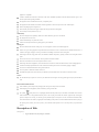
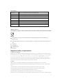
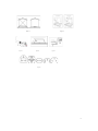
Contents
u
u
u
u
u
u
u
u
u
Important Information
Description of Hob
Operation
Maintenance and cleaning
Troubleshooting
Instruction for installer
Technical data
Important safety requirements
Installation
Please read this instruction manual before using the appliance!
Important Information
You MUST read these warnings carefully before installing or using the hob.
If the supply cord is damaged, it must be replaced by the manufacturer, its service agent or similarly qualified persons in order to avoid a
hazard.
This appliance is not intended for use by persons (including children) with reduced physical, sensory or mental capabilities, or lack of
experience and knowledge, unless they have been given supervision or instruction concerning use of the appliance by a person
responsible for their safety.
Children should be supervised to ensure that they do not play with the appliance
Installation
Prior to installation, ensure that the local distribution conditions (nature of the gas and gas pressure) and the adjustment of the
2
appliance are compatible.
It shall be installed and connected in accordance with current installation regulations. Particular attention shall be given to the
relevant requirements regarding ventilation.
This appliance must be installed and serviced by a competent person
This appliance shall be installed in accordance with the regulations in force and only used in a well ventilated space.
Remove all packaging before using the hob
Ensure that the gas and electrical supply complies with the type stated on the rating label
Do not attempt to modify the hob in any way.
Child Safety
This hob is designed to be operated by adults. Do not allow children to play near or with the hob.
The hob gets hot when it is in use.
Children should be kept away until it has cooled.
Children can also injure themselves by pulling pans or pots off the hob.
During Use
This hob is intended for domestic cooking only. It is not designed for commercial or industrial purposes.
When in use a gas cooking appliance will produce heat and moisture in the room in which it has been installed. Ensure there is a
continuous air supply, keeping air vents in good condition or installing a cooker hood with a venting hose.
When using the hob for a long period of time, the ventilation should be improved, by opening a window or increasing the extractor
speed.
Do not use hob if it is in contact with water. Do not operate the hob with wet hands.
Ensure the control knobs are in the closed position when not in use.
When using other electrical appliances, ensure the cable does not come into contact with the hot surfaces of the cooking appliance.
Unstable or misshapen pans should not be used on the hob as unstable pans can cause an accident by tipping or spillage.
Never leave the hob unattended when cooking with oil and fats.
Never use plastic or aluminum foil dishes on the hob.
Perishable food, plastic items and aerosols may be affected by heat and should not be stored above or below the hob unit.
Service
The hob should only be repaired or serviced by an authorized Service Engineer and only genuine approved spare parts should be
used.
Environmental Information
After installation, please dispose of the packaging with due regard to safety and the environment.
When disposing of an old appliance, make it unusable, by cutting off the cable.
The symbol
on the product or on its packaging indicates that this product may not be treated as household waste. Instead it
shall be handed over to the applicable collection point for the recycling of electrical and electronic equipment. By ensuring this
product is disposed of correctly, you will help prevent potential negative consequences for the environment and human health,
which could otherwise be caused by inappropriate waste handling of this product. For more detailed information about recycling of
this product, please contact your local city office, your household waste disposal service or the shop where you purchased the
product.
Description of Hob
(See Figure 1*)
1.
Top panel(Stainless steel, tempered glass, enameled)
3
2.
Wok burner
3.
Rapid Burner
4.
Semi-rapid Burners
5.
Auxiliary Burner
6.
Control knobs
Operation
Lighting Burners – Simply press the knob in, turn anticlockwise to maximum and the burner will ignite. Before releasing knob,
ensure a flame is established, if the burner fails to ignite, put into off position and try again.
If in case of a power failure or failure of the ignition, a match or lighting devise can be used. Care must be taken when using this method.
The device shall not be operated for more than 15s. If after 15s the burner has not lit, stop operating the device and open the compartment
door and/ or wait at least 1 min before attempting a further ignition of the burner.
In the event of the burner flames being accidentally extinguished, turn off the burner control and do not attempt to re-ignite the burner for
at least 1 min.
If you cannot light the flame even after several attempts, check the "cap" and “crown” (see diagram – figure 1) are in the correct position.
To put the flame out, turn the knob to the symbol
”
1. Burner Cap
2. Burner crown
3. Burner plate
4. Ignition electrode
5. Thermocouple (See Figure 2*)
When switching on the mains, after installation or a power cut, it is quite normal for the spark generator to be activated automatically.
To ensure maximum burner efficiency, you had better use pots and pans with a flat bottom fitting the size of the burner used (see table).
Burner
Minimum Diameter
Maximum diameter
Wok
240mm
260mm
Large (rapid)
180 mm
260 mm
Medium (semi-rapid)
120 mm
220 mm
80 mm
160 mm
Small (auxiliary)
If you using a saucepan which is smaller than the recommended size, the flame will spread beyond the bottom of the vessel, causing the
handle to overheat.
Take care when frying food in hot oil or fat, as the overheated splashes could easily ignite.
Warning: As soon as a liquid starts boiling, turn down the flame so that it will barely keep the liquid simmering. If the control knobs
become difficult to turn, please contact your local service centre. (See figure 3*)
Maintenance and Cleaning
Before any maintenance or cleaning can be carried out, you must DISCONNECT the hob from the electricity supply.
The hob is best cleaned whilst it is still warm; as spillage can be removed more easily than if it is left to cool.
The Hob Panel
Regularly wipe over the hob top using a soft cloth well wrung out in warm water to which a little washing up liquid has been added.
Avoid the use of the following:1) household detergent and bleaches;2) pads unsuitable for non-stick saucepans;3) steel wool pads;4)
bath/sink stain removers.
Pan Supports
If washing them by hand, take care when drying them as the enameling and drying process occasionally leaves rough edges. If necessary,
remove stubborn stains using a paste cleaner.
4
The Burners
The burner caps and crowns can be removed for cleaning. Wash the burner caps and crowns using hot soapy water, and remove marks
with a mild paste cleaner. A well moistened soap steel wool pad can be used with caution, if the marks are particularly difficult to remove.
After cleaning, be sure to wipe dry with a soft cloth.
Ignition electrode
The electric ignition is obtained through a ceramic "electrode" and a metal electrode. Keep these components very clean, to avoid lighting
difficulties, and check that the burner crown holes are not obstructed.
Thermocouple
The thermocouple is very crucial for cutting gas supply in case of flame out during cooking, be sure to keep them in very clean condition.
Troubleshooting
Problem
Corrective action
• There is no spark when lighting the gas
• Check that the unit is plugged in and the electrical supply is
switched on
• Check the mains fuse has not blown
• Check the burner cap and crown have been replaced correctly, e.g.
after cleaning.
• The gas ring burns unevenly
• Check the main jet is not blocked and the burner crown is clear of
food particles.
• Check the burner cap and crown have been replaced correctly, e.g.
after cleaning.
Instructions for the Installer
Overall dimensions
Width: 590mm
Depth: 510mm (For tempered glass models)
Width: 590mm
Depth: 500mm (For other models)
Cut out dimensions
Width: 553mm
Depth: 473mm
Technical Data
Burner configuration
NG
LPG
Injector Dia. (mm)
Gas category
kW
I2H(20)/ I2E(20)/ I2E+
I2Lw
I2Ls
Wok burner
1.38
1.48
1.95
3.3
Rapid burner
1.18
1.2
1.47
0.92
1.0
0.75
0.86
Semi
Injector Dia. (mm)
I3B/P(30)/ I3+
kW
I3B/P(37)
I3B/P(50)
0.92
0.86
0.84
3.3 (241g/h)
2.5
0.80
0.72
0.70
2.5 (182.5 g/h)
1.23
1.5
0.63
0.58
0.57
1.0
1.0
0.53
0.49
0.45
rapid
1.5 (109.5 g/h)
burner
Auxiliary
1.0 (73 g/h)
burner
5
Gas category
I3+
BE, FR, IT, LU, IE, GB, GR, PT, ES, CY, CZ, LT, SK, CH, SI
28~30/37
I3B/P(30)
LU, NL, DK, FI, SE, CY, CZ, EE, LT, MT, SK, SI, BG, IS, NO, TR, HR, RO, IT, HU
I3B/P(37)
PL
I3B/P(50)
AT, DE, CH, SK
I2Lw
PL
I2Ls
PL
I2E+
BE, FR
I2H(20
FR, IT, BE, NL, DK, IE, GB, GR, ES, PT, AT, FI, SE CZ, EE, HU, LV, LT, SK, SI, IS, NO,
I2E(20)
DE, LU, PL
Note: when injectors are changed, the new one should be marked by the gas technician.
Appliance Class: 3
This appliance complies with the following E.E.C. Directives: 2006/95, 93/68, 2004/108 and 90/396.
Electric:
BS plug (230 V 50 Hz supply, 3 core flexible cable with non rewireable plug fitted with a 3 amp cartridge fuse.):
GB, TR, CY, MT
VDE plug
FR, BE, NL, GR, ES, PT, AT, FI, SE, CZ, EE, HU, LV, LT, SK, SI, IS, NO, TR, BG, HR, RO, DE, LU,PL, CY,
MT
Italy plug: IT
Swiss plug: CH
Denmark plug: DK
(Pls see figure 8)
Important safety requirements
Provision for ventilation
The hob should not be installed in a bed sitting room with a volume of less than 20m . If it is installed in a room of volume less than 5m
an air vent of effective area of 110cm is required. If it is installed in a room of volume between 5m and 10m
an air vent of effective
area of 50cm is required, while if the volume exceeds 11m no air vent is required. However, if the room has a door which opens
directly to the outside no air vent is required even if the volume is between 5m and 11m . If there are other fuel burning appliances in
3
the same room, which should be consulted to determine the requisite air vent requirements.
Location
The hob may be located in a kitchen, a kitchen/diner or bed sitting room, but not in a bathroom, shower room or garage.
Before making the cut out in the worktop ensures that there is a minimum distance of 55 mm between the rear edge of the hob and the
wall.
A minimum distance of 100 mm must be left between the side edges of the hob and any adjacent cabinets or walls.
The minimum distance combustible material can be fitted above the hob in line with the edges of the hob is 400 mm.
If it is fitted below 400 mm a space of 50 mm must be allowed from the edges of the hob.
The minimum distance combustible material can be fitted directly above the hob is 700 mm. (See Figure 4*)
Warning: The use of a gas cooking appliance results in the production of heat and moisture in the room in which it is installed. Ensure that
6
the kitchen is well ventilated: keep natural ventilation holes open or install a mechanical ventilation device.
Prolonged intensive use of the appliance may call for additional ventilation, for example opening of a window, or more effective
ventilation, for example increasing the level of mechanical ventilation where present.
Installation
IMPORTANT: The hob must be installed by a competent person to the relevant Gas Standards. Please, ensure that, once the hob is
installed, it is easily accessible for the engineer in the event of a breakdown.
WHEN THE HOB IS FIRST INSTALLED
Once the hob has been installed, it is important to remove any protective materials, which were put on in the factory.
Any gas installation must be carried out by a competent person.
The manufacturer will not accept liability, should the above instructions or any of the other safety instructions incorporated in this book
be ignored.
On the end of the shaft, which includes the GJ 1/2" threaded elbow, adjustment is fixed so that the washer is fitted between the
components as shown in the diagram. Screw the parts together without using excessive force.
mportant: When installing the hob above a built-in oven, the oven should be placed on two wooden strips; in the case of a joining
cabinet surface, remember to leave a space of at least 45 x 560 mm at the back.
When installing on a built-in oven without forced ventilation, ensure that there are air inlets and outlets for ventilating the interior of the
cabinet adequately.
Gas Connection
Connection to the gas supply should be with either rigid or semi-rigid pipe, i.e. steel or copper. The connection should be suitable for
connecting to RC 1/2 (1/2 BSP male thread). When the final connection has been made, it is essential that a thorough leak test is carried
out on the hob and installation. Ensure that the main connection pipe does not exert any strain on the hob. When a flexible tube is used,
keep that it cannot contact with a moveable part of the housing unit and does not pass through any space susceptible of becoming
congested.
It is important to install the elbow correctly, with the shoulder on the end of the thread, fitted to the hob connecting pipe. Failure to ensure
the correct assembly will cause leakage of gas.
A: End of shaft with 1/2 BSP male thread
B: Washer
C: Connector nut
D: Barb connector for hose (See Figure 5*)
Cut Out dimensions
The dimensions of the cut-out are given in the diagram. (Dimensions are given in mm.)
(See Figure 6*)
Electrical connections
Any electrical work required to install this hob should be carried out by a qualified electrician or competent person
The HOB MUST BE EARTHED
This hob is designed to be connected to AC electrical supply.
Before switching on, make sure the electricity supply voltage is the same as that indicated on the hob rating label.
Ensure that the hob supply cable does not come into contact with surfaces with temperatures higher than 50 deg. C.
Fitting the Hob into the worktop
Carry out the building in of the hob as follows:
Put the seals supplied with the hob, on the edges of the cut out taking care that the seals meet without overlapping;
Place the hob in the cut out, taking care that it is centered
7
Fix the hob with the relevant fixing clamps and screws, as shown in the diagram. When the screws have been tightened, the excess
seal can be removed. (See Figure 7*)
The edge of the hob forms a double seal which prevents the build-up of liquids.
Check the hob after installation & before using
When the hob has been fully installed it will be necessary to check the minimum flame setting. To do this, follow the step below,
---Turn the gas tap to MAX position and ignite
---Set the gas tap to the MIN flame position then turn the control knob from MIN to MAX several times. If the flame is unstable or is
extinguished follow the procedure below.
Procedure:
---Re-ignite the burner and set to MIN.
---Remove the control knob and use a thin bladed screwdriver to turn the adjustment screw until the flame is steady and does not
extinguish, when the knob is turned from MIN to MAX.
---Repeat the adjustment procedure for all burners.
Pressure Testing:
---Remove left hand pan support and front left burner cap and crown.
---Fit manometer tube over the injector.
---Turn on the burner gas supply and ignite another burner.
---Turn off the burner supplies.
Conversion form NG to LPG or from LPG to NG
Important
The replacement / conversion of the gas hob should only be undertaken by a competent person.
It is important to note that this model is designed for use with which gas category. Please check the note on the appliance. But it can be
converted from one gas category to another providing the correct injectors are fitted and the gas rate is adjusted to suit.
Method
l
Ensure that the gas taps are in the
l
Isolate the hob from the electrical supply
l
Remove all pan supports, burner caps, rings, crowns and control knobs
l
With the aid of a 7mm box spanner the burner injectors can then be unscrewed and replaced by the appropriate injectors.
” position
To adjust the gas rate
With the aid of a thin bladed screwdriver completely tighten down by the pass adjustment screw, which is located down the center of the
gas tap control shaft. Upon completion stick the replacement rating plate on the under side of the hob.
Figures
Figure 1
Figure 2
8
Figure 3
Figure5
Figure 4
Figure6
Figure7
Figure8
9