1
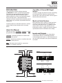
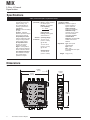
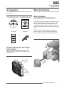
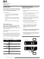
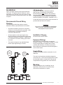
MIX
2 -Wire, 4-Channel
Signal Isolator
November 2008
206-774-00A
2-Wire, 4-Channel
Signal Isolator
MIX
Table of Contents
Introduction....................................................................................................................................................... 3
About this Manual ........................................................................................................................................ 3
Model and Serial Numbers .......................................................................................................................... 3
Inputs and Ouputs ........................................................................................................................................ 3
The 2-Wire, 4-Channel MIX Signal Isolator ................................................................................................. 3
Specifications ................................................................................................................................................... 4
Dimensions ....................................................................................................................................................... 4
Accessories ...................................................................................................................................................... 5
Docking Clamping Tool and Loop ID Location ............................................................................................. 5
Wire Termination .......................................................................................................................................... 5
Wire Installation ........................................................................................................................................... 5
Calibration ......................................................................................................................................................... 6
Calibration Setup ......................................................................................................................................... 6
Calibration Procedure .................................................................................................................................. 6
Installation......................................................................................................................................................... 7
Recommended Ground Wiring Practices ..................................................................................................... 7
CE Conformity .............................................................................................................................................. 7
Electrical Connections ................................................................................................................................. 7
Installation Category .................................................................................................................................... 7
Equipment Ratings ....................................................................................................................................... 7
Supply Wiring ............................................................................................................................................... 7
Mounting ...................................................................................................................................................... 7
Cleaning and Maintenance .......................................................................................................................... 8
Replacement of Consumable Materials ....................................................................................................... 8
Customer Support ........................................................................................................................................ 8
Symbols ....................................................................................................................................................... 8
MIX
2-Wire, 4-Channel
Signal Isolator
Introduction
The 2-Wire, 4-Channel MIX Signal
Isolator
This is the users’ manual for Moore Industries’
miniMOORE MIX 2-Wire, 4-Channel Signal Isolator.
The output loop-powered MIX provides 1000Vrms
input-to-output, and channel-to-channel, signal
isolation between up to four non-isolated transmitters
and a receiving device. This eliminates faulty
readings in process measurements caused by ground
loops, motor noise, and other unpredictable electrical
interference.
The MIX is a highly cost-effective means of protecting
process signals from distortions associated with
ground loops, motor noise and other common types of
ambient electrical interference.
Model and Serial Numbers
Moore Industries uses a system of model and serial
numbers to keep track of all of the information on
every unit it sells and services. If a problem occurs
with your MIX, check for a tag affixed to the unit
listing these numbers. Supply the Customer Support
representative with this information when calling.
The MIX provides four individual channels of 4-20mA
outputs ready for direct interface with a receiving
device.
About this Manual
Wherever you see a “WARNING”, “Caution” or “Note”
pay particular attention.
WARNING - Hazardous procedure or condition that
could injure the operator.
Caution - Hazardous procedure or condition that could
damage or destroy the unit.
Inputs and Outputs
The 2-wire, 4-channel MIX has four independent
4-20mA inputs with four corresponding isolated
4-20mA outputs (See Figure 1). Each channel has its
own zero (±5%) and span (±10%) pots for adjustment
as needed.
Note - Information that is helpful for a procedure,
condition, or operation of the unit.
Figure 1. The MIX has four, 2-wire, 4-20mA inputs and four 4-20mA outputs
INPUT
Channel B
Channel C
Channel D
+
-
+
INPUT
-
A
A
TOP VIEW
Ch-C
(-)
Ch-A
(+)
(-)
(+)
(+)
(-)
POWER
SUPPLY
MIX 4-CHANNEL
4-20mA
ONLY
4-20mA
4-20mA
RIGHT SIDE VIEW
4-20mA
4-20mA
Channel A
+
PS
+
-
4-20mA
-
+
RECEIVER
POWER
SUPPLY
+
4-20mA
ONLY
+
-
+
INPUT
-
B
B
-
+
PS
4-20mA
-
+
-
(+)
RECEIVER
+
4-20mA
ONLY
+
-
+
INPUT
-
C
C
4-20mA
-
+
-
+
INPUT
-
D
D
Ch-D
-
+
PS
-
4-20mA
(-)
+
-
4-20mA
ONLY
(-)
Ch-B
BOTTOM VIEW
RECEIVER
POWER
SUPPLY
+
(+)
-
+
PS
(-)
Ch-D
POWER
SUPPLY
+
-
Channel C
Ch-B
(+)
(-)
(+)
RECEIVER
4-20mA
4-20mA
4-20mA
4-20mA
Channel D
Channel A
(+)
(-)
Ch-C
Channel C
Ch-A
Channel B
OUTPUT
The Interface Solution Experts
3
MIX
2-Wire, 4-Channel
Signal Isolator
Specifications
2-Wire, 4-Channel Output-Loop Powered Isolator
Performance Accuracy: ±0.1% of span
(includes input accuracy,
output accuracy, and
the combined effects of
linearity, hysteresis and
repeatability)
Stability: ±0.2% of reading
per year
Isolation: 1000Vrms
between inputs and outputs
and channel to channel
Output Response Time:
100msec maximum to 99%
of output change; 50msec
to 90% output change
DC Input Resistance:
50 ohms for current;
1 Mohm for voltage
Ripple: <10mV peak-topeak maximum measured
across a 250 ohm resistor
Over-Voltage Protection:
42V maximum on output;
42V reverse polarity
protection on output
Maximum Input Over
Range: 100mA maximum
for current inputs
Burden: 1V maximum
Load Capability:
Performance
(continued)
Vs - 12Vdc
= ohms
0.02A
Output Current
Limiting: 25mA typical;
30mA maximum.
Operating Range:
-40°C to +70°C
(-40°F to +185°F)
@ 12V-30V,
Ambient
Conditions
-40°C to +55°C
(-40°F to +131°F)
@ 12V-42V
Storage Range:
-40°C to +85°C
(-40°F to +185°F)
Ambient Ambient Temperature
Conditions Effect:
(Continued) ±0.007% of span/°C
typical; ±0.015% of
span/°C maximum.
Relative Humidity:
0-95% non-condensing
RFI/EMI Immunity:
Less than ±0.1% of span
error when tested at
10V/m@20-1000MHz
Common Mode
Rejection: Exceeds 95dB
at 60Hz with a limit of
500Vrms
Adjustment
Weight
Type: Front panel
potentiometers
Span: ±10%
Zero: ±5%
(non-interactive when span
is set first)
241g (8.5 oz)
Dimensions
Figure 2. 2-wire, 4-channel MIX dimensions
114mm
(4.5 in)
25.4mm
(1.0 in)
111mm
(4.38 in)
+
-
+
INPUT
-
A
A
+
PS
+
-
4-20mA
-
+
-
4-20mA
ONLY
MULTI-CHANNEL
ISOLATOR
POWER
SUPPLY
MIX 4-CHANNEL
RECEIVER
POWER
SUPPLY
4-20mA
ONLY
+
-
+
INPUT
-
B
B
-
+
PS
4-20mA
-
+
-
+
RECEIVER
102mm
(4.03 in)
POWER
SUPPLY
4-20mA
ONLY
+
-
+
INPUT
-
C
C
-
+
PS
4-20mA
-
+
-
+
RECEIVER
POWER
SUPPLY
4-20mA
ONLY
+
-
+
INPUT
-
D
D
-
+
PS
-
4-20mA
+
-
+
RECEIVER
4
The Interface Solution Experts
MIX
2-Wire, 4-Channel
Signal Isolator
Accessories
Your miniMOORE MIX unit comes with the following
accessories:
Figure 3. MIX miniMOORE accessories
miniMOORE User Manuals on CD
miniMOORE Quick Set-Up Guide
Visit Us at: www.miinet.com
November 2008
For more information, visit us at: www.miinet.com
© 2008 Moore Industries-International, Inc.
750-75E05-01AN
Loop ID Label
Refer to Figure 1 for wire termination for your MIX unit.
Wire Installation
miniMOORE Quick Set-Up Guide
Specifications and information subject to change without notice.
©2008 Moore Industries-International, Inc.
All rights reserved.
Wire Termination
700-701-91A
Clamping Tool
The connectors must be removed from unit, to
properly install wires in each of the connectors.
Figure 5 below, illustrates how to use the wiring clamp
tool to correctly install the wire into connector. Insert
clamp in proper slot and press downward, this will
momentarily open terminal slot. Slide wire into place,
and then release pressure on clamp tool to lock wire in
place.
After correct wiring, following the wire termination
shown in Figure 1, place connector back onto unit.
Refer to Figure 4 for proper storage of clamping tool.
A
B
C
Figure 5. Using the clamping tool
D
-1067A
Docking Clamping Tool and Loop ID
Label Location
Figure 4 below illustrates proper location to dock
clamping tool after use and correct location for the
Loop ID label.
Figure 4. MIX miniMOORE accessories
Dock Clamp Tool
in connector
as shown for
storage.
Slide Loop ID
label into place
under transparent
front panel.
The Interface Solution Experts
5
MIX
2-Wire, 4-Channel
Signal Isolator
Calibration
Calibration Procedure
Before placing your MIX into service, a bench check
of basic operation is recommended to ensure that the
unit hasn’t sustained any damage during transit, and
to set zero and span for your application.
Every unit should be:
• Checked to verify that the appropriate MIX
model has been ordered for the intended
application.
With the unit incorporated into the appropriate setup
(as illustrated in Figure 6):
1. Apply the appropriate power to the “PS” side of
the setup.
2. Set the current calibrator to 0% of the rated span
for the type of MIX being calibrated.
For example, 4mA for a 4-20mA input unit.
• Connected in a calibration setup (described
later in this section) and checked for desired
output.
3. Adjust the MIX zero potentiometer (pot) until the
voltmeter in the setup reads 1V plus/minus the
stated accuracy specification.
• Adjusted for desired zero and span settings.
4. Set the calibrator to 100% of the rated span
(full scale) of MIX being calibrated.
For example, 20mA for a 4-20mA input unit.
Calibration Setup
Table 1 lists the equipment you will need to bench
check the MIX. These materials are not supplied by
Moore Industries, but should be available in
environments suited for calibration and maintenance of
electronic instruments.
Figure 6 shows the calibration setup for the 2-wire,
4-channel MIX.
Moore Industries recommends that the procedures in
this section be carried out at a technician’s bench or
in a similar lab-type environment. Do not calibrate the
MIX in the field or while installed in its application.
5. Adjust the span potentiometer (pot) until the
voltmeter reads 5V plus/minus the stated
accuracy specification across the load
resistor.
6. Repeat steps 2 through 5 until the voltage across
the load resistor is stable and within the rated unit
accuracy at both 0% and 100% of span.
7. Move the calibrator and power source to the next
channel and repeat steps 1 through 6 for each of
the remaining channels.
Figure 6. Calibrating the 2-wire, 4-channel MIX
CURRENT
CALIBRATOR
(SOURCE MODE)
Table 1. Equipment for MIX calibration
Device
Current
Calibrator
Power
Supply
Load
Resistor
Multimeter
Specification
–
TOP VIEW
Adjustable, calibrated to an accuracy of
±0.025% (EDC Model CR 103 or MV 105, or
equivalent)
Calibrated, 12-42Vdc, ±10%, nominal
BOTTOM VIEW
250 ohms (±0.01%) precision
Calibrated to an accuracy of ±0.025%,
minimum (Keithley Model 197, or Fluke
Model 8840 or 8842, or equivalent)
–
VOLTMETER
Screwdriver
6
+
Standard (Blade-type), head width 2.5 mm
(0.10 in), maximum
The Interface Solution Experts
250Ω
+
+
–
12-42VDC
POWER
SOURCE
MIX
2-Wire, 4-Channel
Signal Isolator
Installation
CE Conformity
Figure 2 on page 4 shows the physical dimensions
of the MIX. To install the MIX on a DIN-rail, set the
appropriate lip on the back of the unit on the top edge
of the DIN-rail and pivot downward until the unit snaps
into place.
Consult the factory for the most current information on
products that have been CE certified.
Recommended Ground Wiring
Practices
The following ground wiring practices must be
followed to ensure proper performance of the MIX:
•
Any Moore Industries’ product in a metal case,
enclosure or housing should be grounded. Units
in DIN housings, for example, should be
mounted on grounded rail.
•
All input signals to, and output signals from,
Moore Industries’ products should be wired using
a shielded, twisted pair technique. Shields are to
be connected to an earth or safety ground at the
unit itself.
•
Installation of any Moore Industries’ products
that carry the CE certification (Commission
Electrotechnique) must adhere to the guidelines
above in order to meet the requirements set forth
in applicable EMC (Electromagnetic Compatibility)
directives (EN55011, EN 50082-1, EN50082-2, etc.).
The maximum length of any unshielded input
and/or output signal wiring is 2 inches.
Figure 7. Installing the 2-wire, 4-channel MIX
WARNING:
If this unit is used in a manner not specified by
Moore Industries, the protection provided by
the equipment may be impaired.
Installation Category
All terminals are rated to CATII.
Equipment Ratings
Moore Industries’ transmitters do not generate
hazardous voltages. They measure voltage or current
inputs, and generate low voltages and currents
(<42Vdc and <25mAdc). Products connected to
Moore Industries’ transmitters should be designed to
receive these inputs.
Supply Wiring
NON-ISOLATED
2-WIRE
TRANSMITTER
–
+
+
All power connections shall be made with 16 to 20
AWG wire.
NON-ISOLATED
4-WIRE
TRANSMITTER
POWER
SUPPLY
–
+
MULTI-CHANNEL
ISOLATOR
–
The end of each conductor should be stripped no
more than 8mm. The end of the stripped wire should
be tinned with solder or inserted into a ferrule and
crimped before being placed into a terminal block.
MULTI-CHANNEL
ISOLATOR
Mounting
OR
When mounting the unit or installing it into an
application, ensure that the unit can be easily
removed for maintenance or repairs.
+
–
12-42VDC
POWER
SUPPLY
–
+
CURRENT
DRIVEN
DEVICE
i.e. DCS
+
–
12-42VDC
POWER
SUPPLY
–
+
CURRENT
DRIVEN
DEVICE
i.e. DCS
The Interface Solution Experts
7
MIX
2-Wire, 4-Channel
Signal Isolator
Cleaning and Maintenance
Maintenance of Moore Industries’ products is limited
to keeping the unit clean and the wire terminals free
of oxidation. This is best accomplished by installing
the unit in an area protected from dust, heat, moisture,
and corrosive atmospheres. Yearly visual inspections
should be performed to ensure that the unit is clean
and the electrical connections are in good repair.
Symbols
Table 2 shows the symbols used on Moore Industries’
products, the corresponding IEC/ISO symbol, and its
definition.
Table 2. Symbols on Moore Industries’ Products
O
Replacement of
Consumable Materials
IEC/ISO
Symbol
No consumable materials are used in the Moore
Industries’ products covered by EN 61010-1.
Customer Support
Recognized as the industry leader for delivering
top quality products and services to our customers,
Moore Industries is dedicated to quality. If any
product fails to perform up to rated specifications,
call us for help. Our team of technicians and
engineers will provide timely, accurate, and practical
answers to your process instrumentation questions.
Symbol on
Moore
Industries
Product
Definition
+PS
– PS
DCC
Direct Current
AC
ACC
Alternating Current
AC or DC
Direct and Alternating Current
GND
Protected Earth Terminal
If problems involve a particular MIX, there are several
pieces of information you can gather before you call
the factory that will help our staff get your answers
more efficiently. When you call, please have:
Protective Conductor Terminal
• The model number of the unit in question
Equipment protected throughout
by double insulation or
reinforced insulation (equivalent
to Class II of IEC 536)
• The serial number of the unit in question
• The job number (if available)
Caution (See manual for
information)
• The purchase order under which the unit was
shipped (if available)
Not Specified
+INPUT
– INPUT
Positive Input
Negative Input
Not Specified
+OUTPUT
– OUTPUT
Positive Output
Negative Output
Not Specified
NO
NC
CM
Normally Open
Normally Closed
Common
Not Specified
UNO
UNC
Upper Normally Open
Upper Normally Closed
Not Specified
LNO
LNC
Lower Normally Open
Lower Normally Closed
Not Specified
X
Transmitter Excitiation
Factory contact information is on the back cover.
8
The Interface Solution Experts
Declaration of Conformity
EMC Directive 2004/108/EC EN61326
• Manufacturer’s Name:
• Manufacturer’s Address:
Moore Industries-International, Inc.
16650 Schoenborn Street
North Hills, CA 91343-6196
USA
We herewith attest that the product detailed below meets EMC specifications defined by
EN61326-1, Electromagnetic Compatibility Requirements for Electrical Equipment for Control Use.
• Product Name:
2-wire, 4-channel Signal Isolator, MIX
MODEL
• Model Number(s):
MIX
*
/
INPUT /
*
OUTPUT
*
/
POWER
/
*
OPTIONS /
HOUSING
*
*
* Indicates any input, output, power, option and housing as stated in the product data sheet.
• Supplementary Information:
None.
November 2008
Date
Diane
Dian
ne Kulisek
Quality Assurance Director
Robert Stockham
Moore Industries-Europe General Mgr.
European Contact: Your Local Moore Industries Sales and Service Office
United States • [email protected]
Tel: (818) 894-7111 • FAX: (818) 891-2816
Australia • [email protected]
Tel: (02) 8536-7200 • FAX: (02) 9525-7296
Belgium • [email protected]
Tel: 03/448.10.18 • FAX: 03/440.17.97
The Netherlands • [email protected]
Tel: (0)344-617971 • FAX: (0)344-615920
China • [email protected]
Tel: 86-21-62491499 • FAX: 86-21-62490635
United Kingdom • [email protected]
Tel: 01293 514488 • FAX: 01293 536852
RETURN PROCEDURES
To return equipment to Moore Industries for repair, follow these four steps:
1. Call Moore Industries and request a Returned Material Authorization (RMA) number.
Warranty Repair –
If you are unsure if your unit is still under warranty, we can use the unit’s serial number
to verify the warranty status for you over the phone. Be sure to include the RMA
number on all documentation.
Non-Warranty Repair –
If your unit is out of warranty, be prepared to give us a Purchase Order number when
you call. In most cases, we will be able to quote you the repair costs at that time.
The repair price you are quoted will be a “Not To Exceed” price, which means that the
actual repair costs may be less than the quote. Be sure to include the RMA number on
all documentation.
2. Provide us with the following documentation:
a) A note listing the symptoms that indicate the unit needs repair
b) Complete shipping information for return of the equipment after repair
c) The name and phone number of the person to contact if questions arise at the factory
3. Use sufficient packing material and carefully pack the equipment in a sturdy shipping container.
4. Ship the equipment to the Moore Industries location nearest you.
The returned equipment will be inspected and tested at the factory. A Moore Industries representative will contact the person designated on your documentation if more information is
needed. The repaired equipment, or its replacement, will be returned to you in accordance
with the shipping instructions furnished in your documentation.
WARRANTY DISCLAIMER
THE COMPANY MAKES NO EXPRESS, IMPLIED OR STATUTORY WARRANTIES (INCLUDING ANY WARRANTY OF MERCHANTABILITY OR
OF FITNESS FOR A PARTICULAR PURPOSE) WITH RESPECT TO ANY
GOODS OR SERVICES SOLD BY THE COMPANY. THE COMPANY DISCLAIMS ALL WARRANTIES ARISING FROM ANY COURSE OF DEALING
OR TRADE USAGE, AND ANY BUYER OF GOODS OR SERVICES FROM
THE COMPANY ACKNOWLEDGES THAT THERE ARE NO WARRANTIES
IMPLIED BY CUSTOM OR USAGE IN THE TRADE OF THE BUYER AND
OF THE COMPANY, AND THAT ANY PRIOR DEALINGS OF THE BUYER
WITH THE COMPANY DO NOT IMPLY THAT THE COMPANY WARRANTS
THE GOODS OR SERVICES IN ANY WAY.
ANY BUYER OF GOODS OR SERVICES FROM THE COMPANY
AGREES WITH THE COMPANY THAT THE SOLE AND EXCLUSIVE REMEDIES FOR BREACH OF ANY WARRANTY CONCERNING THE GOODS OR
SERVICES SHALL BE FOR THE COMPANY, AT ITS OPTION, TO REPAIR
OR REPLACE THE GOODS OR SERVICES OR REFUND THE PURCHASE
PRICE. THE COMPANY SHALL IN NO EVENT BE LIABLE FOR ANY CONSEQUENTIAL OR INCIDENTAL DAMAGES EVEN IF THE COMPANY FAILS
IN ANY ATTEMPT TO REMEDY DEFECTS IN THE GOODS OR SERVICES
, BUT IN SUCH CASE THE BUYER SHALL BE ENTITLED TO NO MORE
THAN A REFUND OF ALL MONIES PAID TO THE COMPANY BY THE BUYER
FOR PURCHASE OF THE GOODS OR SERVICES.
United States • [email protected]
Tel: (818) 894-7111 • FAX: (818) 891-2816
Australia • [email protected]
Tel: (02) 8536-7200 • FAX: (02) 9525-7296
© 2008 Moore Industries-International, Inc.
ANY CAUSE OF ACTION FOR BREACH OF ANY WARRANTY BY
THE COMPANY SHALL BE BARRED UNLESS THE COMPANY RECEIVES FROM THE BUYER A WRITTEN NOTICE OF THE ALLEGED
DEFECT OR BREACH WITHIN TEN DAYS FROM THE EARLIEST DATE
ON WHICH THE BUYER COULD REASONABLY HAVE DISCOVERED
THE ALLEGED DEFECT OR BREACH, AND NO ACTION FOR THE
BREACH OF ANY WARRANTY SHALL BE COMMENCED BY THE
BUYER ANY LATER THAN TWELVE MONTHS FROM THE EARLIEST
DATE ON WHICH THE BUYER COULD REASONABLY HAVE DISCOVERED THE ALLEGED DEFECT OR BREACH.
RETURN POLICY
For a period of thirty-six (36) months from the date of shipment, and under
normal conditions of use and service, Moore Industries (“The Company”)
will at its option replace, repair or refund the purchase price for any of its
manufactured products found, upon return to the Company (transportation
charges prepaid and otherwise in accordance with the return procedures
established by The Company), to be defective in material or workmanship.
This policy extends to the original Buyer only and not to Buyer’s customers
or the users of Buyer’s products, unless Buyer is an engineering contractor
in which case the policy shall extend to Buyer’s immediate customer only.
This policy shall not apply if the product has been subject to alteration,
misuse, accident, neglect or improper application, installation, or operation.
THE COMPANY SHALL IN NO EVENT BE LIABLE FOR ANY INCIDENTAL
OR CONSEQUENTIAL DAMAGES.
Belgium • [email protected]
Tel: 03/448.10.18 • FAX: 03/440.17.97
The Netherlands • [email protected]
Tel: (0)344-617971 • FAX: (0)344-615920
China • [email protected]
Tel: 86-21-62491499 • FAX: 86-21-62490635
United Kingdom • [email protected]
Tel: 01293 514488 • FAX: 01293 536852
Specifications and Information subject to change without notice.


![ECT[DIN] [DIN] - Moore Industries International](http://vs1.manualzilla.com/store/data/005778735_1-93255c4f7d497ff32afcfe496e72d982-150x150.png)