1
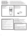
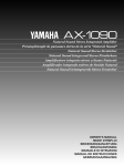
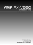
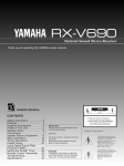
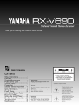
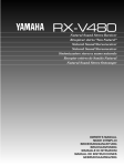
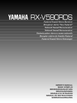
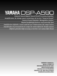
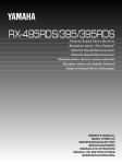
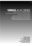
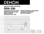
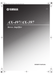
AX-390
Natural Sound Stereo Integrated Amplifier
Préampli/ampli de puissance stéréo de la série “Natural Sound”
Natural Sound Stereo-Verstärker
Natural Sound Integrerad Stereo Förstärkare
Amplificatore integrato stereo a Suono Naturale
Amplificador integrado estéreo de Sonido Natural
Natural Sound Geïntegreerde Stereo Versterker
OWNER’S MANUAL
MODE D’EMPLOI
BEDIENUNGSANLEITUNG
BRUKSANVISNING
MANUALE DI ISTRUZIONI
MANUAL DE INSTRUCCIONES
GEBRUIKSAANWIJZING
SUPPLIED ACCESSORIES
ACCESSOIRES FOURNIS
MITGELIEFERTE ZUBEHÖRTEILE
MEDFÖLJANDE TILLBEHÖR
ACCESSORI IN DOTAZIONE
ACCESORIOS INCLUIDOS
BIJGELEVERDE ACCESSOIRES
●
●
●
●
●
●
●
●
●
●
●
●
●
●
After unpacking, check that the following parts are included.
Après le déballage, vérifier que les pièces suivantes sont incluses.
Nach dem Auspacken überprüfen, ob die folgenden Teile vorhanden sind.
Kontrollera efter det apparaten packats upp att följande delar finns med.
Verificare che tutte le parti seguenti siano contenute nell’imballaggio dell’apparecchio.
Desembale el aparato y verificar que los siguientes accesorios están en la caja.
Controleer na het uitpakken of de volgende onderdelen voorhanden zijn.
Remote Control Transmitter
Emetteur de télécommande
Fernbedienungsgeber
Fjärrkontrollsändare
Telecomando
Transmisor del control remoto
Afstandbediening
This product complies with the radio frequency
interference requirements of the Council Directive
82/499/EEC and/or 87/308/EEC.
Cet appareil est conforme aux prescriptions de la directive
communautaire 87/308/CEE.
Diese Geräte entsprechen der EG-Richtlinie 82/499/EWG
und/oder 87/308/EWG.
Dette apparat overholder det gaeldende EF-direktiv
vedrørende radiostøj.
Questo apparecchio è conforme al D.M.13 aprile 1989
(Direttiva CEE/87/308) sulla soppressione dei
radiodisturbi.
Este producto está de acuerdo con los requisitos sobre
interferencias de radio frequencia fijados por el Consejo
Directivo 87/308 CEE.
Dit product voldoet aan de EEG normen betreffende
radio-frekwentie storingen 82/499/EEG en/of
87/308/EEG.
2
●
●
●
●
●
●
●
Batteries (size AA, R6, UM-3)
Piles (taille AA, R6, UM-3)
Batterien (Größe AA, R6, UM-3)
Batterier (storlek AA, R6, UM-3)
Batterie (dimensioni AA, R6, UM-3)
Pilas (tamaño AA, R6, UM-3)
Batterijen (maat AA, R6, UM-3)
For U.K. customers
If the socket outlets in the home are not suitable for the plug
supplied with this appliance, it should be cut off and an
appropriate 3 pin plug fitted. For details, refer to the
instructions described below.
Note: The plug severed from the mains lead must be
destroyed, as a plug with bared flexible cord is hazardous if
engaged in a live socket outlet.
Special Instructions for U.K. Model
IMPORTANT
THE WIRES IN THE MAINS LEAD ARE COLOURED IN
ACCORDANCE WITH THE FOLLOWING CODE:
Blue: NEUTRAL
Brown: LIVE
As the colours of the wires in the mains lead of this apparatus may
not correspond with the coloured markings identifying the terminals
in your plug, proceed as follows:
The wire which is coloured BLUE must be connected to the
terminal which is marked with the letter N or coloured BLACK. The
wire which is coloured BROWN must be connected to the terminal
which is marked with the letter L or coloured RED. Make sure that
neither core is connected to the earth terminal of the three pin plug.
FEATURES
●
●
●
●
●
60W + 60W (8Ω) RMS Output Power, 0.04% THD,
20–20,000 Hz
High Dynamic Power, Low Impedance Drive
Capability
Continuously Variable Loudness Control
CD DIRECT AMP Switch to Reproduce the Purest
CD Sound
Remote Control Capability
CONTENTS
English
Thank you for selecting this YAMAHA stereo amplifier.
Supplied Accessories .....................................................2
Caution ...........................................................................3
Controls and Their Functions .........................................4
Connections ...................................................................6
Basic Operations ............................................................8
Notes about the Remote Control Transmitter................11
Troubleshooting ............................................................12
Specifications ...............................................................13
CAUTION: READ THIS BEFORE OPERATING YOUR UNIT.
1. To assure the finest performance, please read this manual
carefully. Keep it in a safe place for future reference.
2. Install this unit in a cool, dry, clean place – away from
windows, heat sources, sources of excessive vibration,
dust, moisture and cold. Avoid sources of humming
(transformers, motors). To prevent fire or electrical shock,
do not expose the unit to rain or water.
3. Never open the cabinet. If something drops into the set,
12. AC outlet
Do not connect audio equipment to the AC outlet on the
rear panel if that equipment requires more power than the
outlet is rated to provide.
13. Voltage Selector (General Model only)
The voltage selector on the rear panel of this unit
must be set for your local main voltage BEFORE
plugging into the AC main supply.
Voltages are 110/120/220/240V AC, 50/60 Hz.
contact your dealer.
4. Do not use force on switches, controls or connection
wires. When moving the unit, first disconnect the power
plug and the wires connected to other equipment. Never
pull the wires themselves.
5. The openings on the cabinet assure proper ventilation of
the unit. If these openings are obstructed, the temperature
inside the cabinet will rise rapidly. Therefore, avoid
placing objects against these openings, and install the unit
in well-ventilated condition. Make sure to allow a space of
at least 10 cm behind, on the both sides and above the top
panel of the unit. Otherwise it may not only damage the
unit, but also cause fire.
IMPORTANT
Please record the serial number of this unit in the space
below.
Serial No.:
The serial number is located on the rear of the unit.
Retain this Owner’s Manual in a safe place for future
reference.
WARNING
TO REDUCE THE RISK OF FIRE OR ELECTRIC SHOCK,
DO NOT EXPOSE THIS UNIT TO RAIN OR MOISTURE.
6. Always set the VOLUME control to “– ∞” before starting
the audio source play. Increase the volume gradually to an
appropriate level after playback has been started.
7. Do not attempt to clean the unit with chemical solvents;
The apparatus is not disconnected from the AC power
source as long as it is connected to the wall outlet, even if
the apparatus itself is turned off.
this might damage the finish. Use a clean, dry cloth.
8. Be sure to read the “TROUBLESHOOTING” section
regarding common operating errors before concluding that
the unit is faulty.
9. When not planning to use this unit for long periods of time
(ie., vacation, etc.), disconnect the AC power plug from the
wall outlet.
10. To prevent lightning damage, disconnect the AC power
plug and disconnect the antenna cable when there is an
electrical storm.
11. Grounding or polarization – Precautions should be taken
so that the grounding or polarization of an appliance is not
defeated.
3
CONTROLS AND THEIR FUNCTIONS
FRONT PANEL
1 2
3
4
5
NATURAL SOUND STEREO AMPLIFIER AX-390
MONITOR
POWER
AUX
TAPE 1
TAPE 2
PHONO
TUNER
CD
CD DIRECT
AMP
COPY
VOLUME
BASS
PHONES
A
6
TREBLE
LOUDNESS
9
0
B
ON
ON
OFF
OFF
7
8
1 POWER switch
Press this switch to switch the power on. Press it again to
switch the power off.
* Standby mode <Europe and U.K. models only>
While the power is on, pressing the POWER key on the
remote control transmitter switches the unit to the standby
mode. (In this mode, the power indicator is half illuminated.)
2 Power indicator
Lights up while the power is on.
3 Remote control sensor
Receives signals from the remote control transmitter.
4 Input selector buttons and indicators
Select a program source to listen to. The indicator above the
selected button (source) will light up.
5 CD DIRECT AMP switch
Press this switch inward to listen to a CD source in the purest
sound. (Refer to page 10 for details.)
6 PHONES jack
When you listen with headphones, connect the headphones to
the PHONES jack. When listening with
PHONES
headphones privately, set both the
SPEAKERS A and B switches to the
OFF position.
4
BALANCE
SPEAKERS
A
7 SPEAKERS switches
Set the switch A or B (or both A and B) for the speaker system
(connected to this unit) you will use to the ON position. Set the
switch for the speaker system you will not use to the OFF
position.
8 Tone controls
BASS
Used to increase or decrease the low frequency response.
The 0 position produces flat response.
TREBLE
Used to increase or decrease the high frequency response.
The 0 position produces flat response.
9 BALANCE control
Adjusts the balance of the output volume to the left and right
speakers to compensate for sound imbalance caused by
speaker location or listening room conditions.
0 Continuously variable LOUDNESS control
Used to compensate for the human ears’ loss of sensitivity to
high and low-frequency ranges at low volume.
A VOLUME control
Used to raise or lower the volume level.
English
REMOTE CONTROL TRANSMITTER
The remote control transmitter provided with this unit is designed to control all the most commonly used functions of the unit. If the
CD player, tuner and tape deck connected to this unit are YAMAHA components designed for remote control compatibility, then this
remote control transmitter will also control various functions of each component.
For Control of This Unit
1 Input selector keys
Selects input source.
2 VOLUME +/– keys
Turns the volume level up/down.
YAMAHA HIFI SYSTEM
REMOTE CONTROL TRANSMITTER
AUX
DIR A
DIR B REC/PAUSE
1
2
PLAY
A/B
–
PRESET
+
A/B/C/D/E
DISC
PLAY
3
TAPE 2
TAPE 1
TUNER
1
3 POWER key
Turns the power on/off.
* <Europe and U.K. models only>
While the power is on, pressing the POWER key on the
remote control transmitter switches the unit from the
power-on mode to the standby mode, and vice versa. (In
the standby mode, the power indicator on the front panel is
half illuminated.)
CD
PHONO
POWER
For Other Component Control
VOLUME
2
3
Identify the remote control transmitter keys with your
component’s keys. If these keys are identical, their functions
will be the same. On each key function, refer to the
corresponding instruction on your component’s manual.
1 Tape deck keys
Controls tape deck.
* DIR A, B and A/B are applicable only to double
cassette tape deck.
* For a single cassette deck with automatic reverse
function, pressing DIR A will reverse the direction of
tape running.
2 Tuner keys
Controls tuner.
+: Selects higher preset station number.
–: Selects lower preset station number.
A/B/C/D/E Selects the group (A – E) of preset station
numbers.
3 CD player keys
Controls compact disc player.
* DISC is applicable only to compact disc changer.
5
CONNECTIONS
Before attempting to make any connections to or from this unit, be sure to first switch OFF the power to this unit and to any other
components to which connections are being made.
CONNECTIONS WITH OTHER COMPONENTS
When making connections between this unit and other components, be sure all connections are made correctly, that is to say L (left)
to L, R (right) to R, “+” to “+” and “–” to “–”. Also, refer to the owner’s manual for each component to be connected to this unit.
* If you have YAMAHA components numbered as 1, 2, 3, etc. on the rear panel, connections can be made easily by making
sure to connect the output (or input) terminals of each component to the same-numbered terminals of this unit.
Speakers A
LINE IN
Tape deck 2
LINE OUT
LINE IN
LINE OUT
Tape deck 1
GND
OUTPUT
Turntable
Right
Left
(Europe model)
GND
SPEAKERS
AC OUTLETS
SWITCHED
l00W MAX. TOTAL
MAINS
1
CD
2
PHONO
TUNER
3 or 5 4 or 6
AUX
3
TAPE 1
TAPE
PB
A
4
TAPE 2
REC
OUT
TAPE
PB
REC
OUT
B
A OR B : 8ΩMIN./SPEAKER
A
B : l6ΩMIN./SPEAKER
AUDIO OUT
OUTPUT
OUTPUT
To AC outlet
Right
Compact disc player
Tuner
Video cassette player,
LD player, etc.
: Refer to “ABOUT THE ACCESSORY TERMINALS” on page 7.
6
Left
Speakers B
Connect the SPEAKERS terminals to your speakers with wire
of the proper gauge, cut as short as possible. If the
connections are faulty, no sound will be heard from the
speakers. Make sure that the polarity of the speaker wires is
correct, that is, + and – markings are observed. If these wires
are reversed, the sound will be unnatural and will lack bass.
Do not let the bare speaker wires touch each other and do
not let them touch the metal parts of this unit as this could
damage this unit and/or speakers.
Notes
One or two speaker systems can be connected to this unit.
If you connect only one speaker system, connect it to either
the SPEAKERS A or B terminals.
● Use speakers with the specified impedance shown on the
rear of this unit.
● <General model only>
Banana Plug connections are also possible. Simply insert
the Banana Plug connector into the corresponding terminal.
●
English
CONNECTING SPEAKERS
How to Connect:
Red: positive (+)
Black: negative (–)
2
1
3
➀ Unscrew the knob.
➁ Insert the bare wire.
[Remove approx. 5mm
(1/4”) insulation from
the speaker wires.]
➂ Tighten the knob and
secure the wire.
ABOUT THE ACCESSORY TERMINALS
AC OUTLET(S) (SWITCHED)
GND terminal (For turntable use)
(Europe and General models) .......... 3 SWITCHED OUTLETS
(U.K. model) ........................................ 1 SWITCHED OUTLET
Use these to connect the power cords from your components
to this unit.
The power to the SWITCHED outlets is controlled by this unit’s
POWER switch or the provided remote control transmitter’s
POWER key. These outlets will supply power to any
component whenever this unit is turned on.
The maximum power (total power consumption of
components) that can be connected to the SWITCHED AC
OUTLET(S) is 100 watts.
Connecting the ground wire of the turntable to this terminal will
normally minimize hum, but in some cases better results may
be obtained with the ground wire disconnected.
7
BASIC OPERATIONS
3
2
7
NATURAL SOUND STEREO AMPLIFIER AX-390
MONITOR
POWER
TAPE 2
PHONO
AUX
TAPE 1
TUNER
CD
CD DIRECT
AMP
COPY
VOLUME
BASS
PHONES
TREBLE
BALANCE
1, 6
LOUDNESS
SPEAKERS
A
B
ON
ON
OFF
OFF
4
7
TO PLAY A SOURCE
1
4
Select the speakers to be used.
SPEAKERS
A
B
*
Set to the “ ∞ ” position.
2
3
5
6
Turn the power on.
POWER
ON
ON
OFF
OFF
If you use two speaker systems, press both the A and
B switches.
Play the source.
Select the desired input source by pressing the
corresponding input selector button.
Adjust to the desired output level.
AUX
PHONO
TUNER
CD
* The indicator above the selected button (source) will light
up.
* Note that pressing on each input selector button selects the
source which is connected to the corresponding input
terminals on the rear panel.
7
If desired, adjust the BASS, TREBLE, BALANCE and
LOUDNESS controls, etc. (refer to page 10).
Notes
●
If you select AUX, PHONO, TUNER or CD, be sure that
TAPE 1 and/or TAPE 2 are not being selected.
●
If you select TAPE 1 and TAPE 2 at the same time, the
result will be the sound from the tape deck 1.
●
For TAPE 1 and TAPE 2, whenever the button is pressed,
the corresponding input source is selected or canceled
alternately.
To turn off the power
Press the POWER switch again.
8
English
1, 4
NATURAL SOUND STEREO AMPLIFIER AX-390
MONITOR
POWER
TAPE 2
AUX
TAPE 1
PHONO
TUNER
CD
CD DIRECT
AMP
COPY
VOLUME
BASS
PHONES
TREBLE
BALANCE
2
LOUDNESS
SPEAKERS
A
B
ON
ON
OFF
OFF
TO RECORD A SOURCE TO TAPE
1
Select the source to be recorded.
AUX
PHONO
TUNER
CD
Notes
● VOLUME, BASS, TREBLE, BALANCE, LOUDNESS
controls and CD DIRECT AMP switch settings have no
effect on the material being recorded.
● To dub from tape to tape, select TAPE 2 by pressing it.
Only the following method of dubbing can be made by using
this unit.
RECORDER
SOURCE
* To dub from tape to tape, refer to the “Notes” shown at
right.
* When you select AUX, PHONO, TUNER or CD, make
sure that neither TAPE 1 nor TAPE 2 is also selected.
2
3
4
Tape deck connected to
the TAPE 2 terminals.
→
Tape deck connected to
the TAPE 1 terminals.
Play the source and then turn the VOLUME control up
to confirm the input source.
Begin recording on the tape deck.
To monitor the audio signals being recorded, press the
input selector button for the tape deck being used to
make the recording.
MONITOR
TAPE 2
TAPE 1
COPY
9
Selecting the SPEAKER system
Because one or two speaker systems can be connected to this
unit, the SPEAKERS switches allow you to select speaker
system A or B, or both at once.
SPEAKERS
A
B
ON
ON
OFF
OFF
Using the CD DIRECT AMP switch
You can enjoy the purest possible CD sound from your CD
player by pressing this switch inward. By doing so, CD’s input
signals are sent to the built-in amplifier special for CD directly
bypassing the input selector buttons, the BASS, TREBLE,
BALANCE and LOUDNESS controls, and then sent to the
power amplifier. This signal routing reproduces the purest CD
sound eliminating any alterations to the CD signals.
CD DIRECT
AMP
Adjusting the BALANCE control
Adjust the balance of the output volume to the left and right
speakers to compensate for sound imbalance caused by
speaker location or listening room conditions.
BALANCE
l
0
This control provides compensation for the human ears’ loss of
sensitivity to high and low-frequency ranges at low volume.
This control is adjustable to retain full tonal range at any
volume level.
l
2
2
3
3
4
4
L 5
Adjusting the continuously variable
LOUDNESS control
5 R
1
Adjusting the BASS and TREBLE
controls
LOUDNESS
FLAT
l
30 dB
2
l0
3
4
BASS
l
0
2
l
2
3
3
4
4
5
8
TREBLE
l
5
0
Set to the “FLAT”
position.
9
5
6
7
l
2
2
3
3
4
4
5
5
VOLUME
BASS
: Turn this clockwise to increase (or counterclockwise to decrease) the low frequency
response.
2
l8
l6
l4
20
l2
24
l0
28
8
34
6
4
40
TREBLE : Turn this clockwise to increase (or counterclockwise to decrease) the high frequency
response.
3
50
2
60
Set to the loudest
listening level that you
would listen to.
l
70
0
–dB
3
LOUDNESS
l
FLAT
30 dB
2
l0
3
9
4
8
5
10
6
7
Turn until the desired
volume is gained.
Battery installation
English
NOTES ABOUT THE REMOTE CONTROL TRANSMITTER
Remote control transmitter operation range
2
Remote control
sensor
1
3
Within approximately
6 m (19.7 feet)
30°
30°
Battery replacement
If you find that the remote control transmitter must be used
closer to the main unit, the batteries are weak. Replace both
batteries with new ones.
Notes
● Use only AA, R6, UM-3 batteries for replacement.
● Be sure the polarities are correct. (See the illustration inside
the battery compartment.)
● Remove the batteries if the remote control transmitter will
not be used for an extended period of time.
● If batteries leak, dispose of them immediately. Avoid
touching the leaked material or letting it come in contact with
clothing, etc. Clean the battery compartment thoroughly
before installing new batteries.
Notes
● There should be no large obstacles between the remote
control transmitter and the main unit.
● If the remote control sensor is directly illuminated by strong
lighting (especially an inverter type of fluorescent lamp etc.),
it might cause the remote control transmitter not to work
correctly. In this case, reposition the main unit to avoid direct
lighting.
11
TROUBLESHOOTING
If the unit fails to operate normally, check the following points to determine whether the fault can be corrected by the simple
measures suggested. If it cannot be corrected, or if the fault is not listed in the SYMPTOM column, disconnect the power cord and
contact your authorized YAMAHA dealer or service center for help.
SYMPTOM
CAUSE
REMEDY
The unit fails to turn on when the POWER
switch is pressed.
Power cord is not plugged in or is not
completely inserted.
Firmly plug in the power cord.
No sound.
Incorrect output cord connections.
Connect the cords properly. If the problem
persists, the cords may be defective.
Appropriate input selector button is not pressed. Press the appropriate input selector button
corresponding to the input source.
Set the SPEAKERS switch that corresponds to
the speakers to be used to the ON position.
Speaker connections are not secure.
Secure the connections.
The sound suddenly goes off.
The protection circuit has been activated
because of short circuit etc.
Turning the unit off and then on will reset the
protection circuit.
Only one side speaker outputs the sound.
Incorrect setting of the BALANCE control.
Adjust it to the appropriate position.
Incorrect cord connections.
Connect the cords properly. If the problem
persists, the cords may be defective.
There is a lack of bass, and no ambience.
The + and – wires are connected in reverse at
this unit or speakers.
Connect the speaker wires in the correct phase
(+ and –).
Sound “hums”.
Incorrect cord connections.
Firmly connect the audio plugs. If the problem
persists, the cords may be defective.
No connection from the turntable to the GND
terminal.
Make the GND connection between the
turntable and this unit.
Sound level is low.
The LOUDNESS control is functioning.
Set the LOUDNESS control to the FLAT
position.
The input source cannot be changed,
though any input selector button is
pressed.
The CD DIRECT AMP switch is ON.
Switch off the CD DIRECT AMP switch.
Using the BASS, TREBLE, BALANCE and
LOUDNESS controls does not affect the
tone.
The CD DIRECT AMP switch is ON.
The CD DIRECT AMP switch must be switched
OFF to use those controls.
The volume level is low while playing a
record.
The record is being played on a turntable with
an MC cartridge.
The player should be connected to the unit
through an MC head amplifier (available
separately).
The volume level cannot be increased, or
sound is distorted.
The power to the component connected to the
REC OUT terminals of this unit is off.
Turn the power to the component on.
The remote control transmitter does not
work.
Direct sunlight or lighting (of an inverter type of
flourescent lamp etc.) is striking the remote
control sensor of the main unit.
Change the position of the main unit.
The batteries of this remote control transmitter
are too weak.
Replace the batteries with new ones.
The power to this unit is off.
Turn the power to this unit on.
The sound is degraded when listening with
the headphones connected to the compact
disc player or cassette deck that are
connected with this unit.
12
The SPEAKERS switches are not set properly.
AUDIO SECTION
Minimum RMS Output Power per Channel
8 ohms, 20 Hz to 20 kHz, 0.04% THD ....................60W+60W
6 ohms, 20 Hz to 20 kHz, 0.04% THD ....................65W+65W
Maximum Output Power
6 ohms, 1 kHz, 10% THD
[General model only].............................................95W+95W
Dynamic Power per Channel
(by IHF Dynamic Headroom measuring method)
8/6/4/2 ohms..................................................80/95/115/125W
DIN Standard Output Power per Channel
4 ohms, 1 kHz, 0.7% THD
[Europe model only] .......................................................90W
IEC Power
8 ohms, 1 kHz, 0.04% THD
[Europe model only] .......................................................75W
Power Band Width
8 ohms, 25W, 0.08% THD..............................10 Hz to 40 kHz
Damping Factor
8 ohms, 20 Hz to 20 kHz ......................................100 or more
Input Sensitivity/Impedance
PHONO MM................................................2.5 mV/47 k-ohms
CD/TUNER/TAPE/AUX ..............................150 mV/47 k-ohms
Maximum Input Signal (1 kHz, 0.04% THD)
PHONO MM ..................................................................90 mV
Output Level/Impedance
REC OUT..................................................150 mV/0.6 k-ohms
Headphone Jack Rated Output/Impedance
Output Level (8 ohms, 0.04% THD) ...............................0.42V
Impedance ...............................................................390 ohms
Frequency Response (20 Hz to 20 kHz)
CD/TUNER/TAPE/AUX ..............................................0±0.5 dB
RIAA Equalization Deviation
PHONO MM ..............................................................0±0.5 dB
Total Harmonic Distortion
PHONO MM to REC OUT
20 Hz to 20 kHz, 1V.....................................................0.02%
CD/TUNER/TAPE/AUX to SP OUT
20 Hz to 20 kHz, 30W/8 ohms.....................................0.02%
Signal-to-Noise Ratio (IHF-A Network)
PHONO MM to REC OUT
(5 mV Input Shorted) ....................................................82 dB
CD/TUNER/TAPE/AUX to SP OUT
(Input Shorted, CD DIRECT ON/OFF)...........108 dB/102 dB
English
SPECIFICATIONS
Residual Noise (IHF-A Network, CD DIRECT ON/OFF)
.............................................................................50 µV/140 µV
Channel Separation (Vol. –30 dB)
PHONO MM (Input Shorted, 1 kHz) ...............................65 dB
CD/TUNER/TAPE/AUX
(Input 5.1 k-ohms Terminated, 1 kHz)..........................60 dB
Tone Control Characteristics
BASS: Boost/cut..............................................±10 dB (20 Hz)
Turnover Frequency.......................................(350 Hz)
TREBLE: Boost/cut ........................................±10 dB (20 kHz)
Turnover Frequency ..................................(3.5 kHz)
Continuous Loudness Control .............................– 30 dB (1 kHz)
(Level related equalization)
GENERAL
Power Supply
[U.S.A. and Canada models]..........................AC 120V, 60 Hz
[Europe and U.K. models] ..............................AC 230V, 50 Hz
[General model]....................AC 110/120/220/240V, 50/60 Hz
Power Consumption
[Europe model] ...............................................................130W
[U.K. and General models] .............................................150W
AC Outlets
3 SWITCHED OUTLETS
[Europe and General models]......................100W max. total
1 SWITCHED OUTLET
[U.K. model] .................................................100W max. total
Dimensions (W x H x D) ............................435 x 146 x 309 mm
Weight ..............................................................................7.3 kg
Accessories .....................................Remote control transmitter
Batteries
Specifications are subject to change without notice.
13
YAMAHA
YAMAHA
YAMAHA
YAMAHA
YAMAHA
YAMAHA
YAMAHA
ELECTRONICS CORPORATION, USA 6660 ORANGETHORPE AVE., BUENA PARK, CALIF. 90620, U.S.A.
CANADA MUSIC LTD. 135 MILNER AVE., SCARBOROUGH, ONTARIO M1S 3R1, CANADA
ELECTRONIK EUROPA G.m.b.H. SIEMENSSTR. 22-34, D-25462 RELLINGEN BEI HAMBURG, F.R. OF GERMANY
ELECTRONIQUE FRANCE S.A. RUE AMBROISE CROIZAT BP70 CROISSY-BEAUBOURG 77312 MARNE-LA-VALLEE CEDEX02, FRANCE
ELECTRONICS (UK) LTD. YAMAHA HOUSE, 200 RICKMANSWORTH ROAD WATFORD, HERTS WD1 7JS, ENGLAND
SCANDINAVIA A.B. J A WETTERGRENS GATA 1, BOX 30053, 400 43 VÄSTRA FRÖLUNDA, SWEDEN
MUSIC AUSTRALIA PTY, LTD. 17-33 MARKET ST., SOUTH MELBOURNE, 3205 VIC., AUSTRALIA
VU27730