1
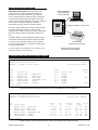
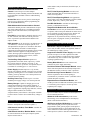
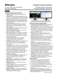
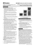
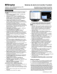
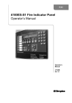
TrueAlarm® Fire Alarm Controls
UL, ULC Listed; FM, CSFM, and
Model 4010 Fire Alarm Control Panel for
®
NYC, MEA Approved*
TrueAlarm Analog Sensors and IDNet™ Addressable Devices
Features
Up to 250 addressable TrueAlarm or IDNet points**
Four, 2 A notification appliance circuits (NACs)
with solid state current protection
UL listed to Standard 864
Installation convenience features:
• Power-limited design with electronic modules
contained on one-piece chassis
• Up-front terminal blocks for wiring access
• Compact NEMA 1 rated cabinet is available in beige or
red and can be pre-shipped for early installation
Setup, programming, and maintenance features:
• Device level ground fault search, locate and isolate
• Auto Program, automatic module and device
programming for general alarm operation
• TrueAlarm individual analog sensing with front panel
information and selection access**
• “Dirty” TrueAlarm sensor maintenance alerts, service
and status reports including “almost dirty”
• Default TrueAlarm sensor device type operation
• Duplicate address error detection
• Front panel or PC programming
• TrueAlarm sensor peak value performance report
†
• WALKTEST™ silent or audible system test
• Software verification simulation mode
Supports the following IDNet devices** :
• Addressable manual stations
• Quad-state zone adapter modules (ZAMs) for initiating
device monitoring
• IDNet ground fault/short circuit isolator base for
TrueAlarm sensors
• Quad-state line powered individual addressable
modules (IAMs) for initiating device monitoring and
relay control
Available option modules include:
• Simplex 4120 Network, DACT, or City interface
• Equipment for Suppression Release Applications
(refer to data sheet S4010-0003)
• RS-232 ports for printers or maintenance terminal
• Class A NAC adapter module
• Additional power supply
Compatible with Simplex:
• TrueAlert™ Addressable Controllers and NAC power
extenders (IDNet controlled and conventional)
• 4003 Voice Control Panel
• 4081 Battery Cabinet with charger for 50 Ah batteries
† Simplex WALKTEST system test is protected under U.S. patent # 4,725,818.
© 2000 Simplex Time Recorder Co. All rights reserved.
4010 TrueAlarm Fire Alarm Control Panel
Description
TrueAlarm fire alarm control panels have the ability
to provide location accuracy for monitoring and control.
When equipped with TrueAlarm analog sensing for
smoke and heat detection, the processing power of the
control panel also has the ability to analyze conditions at
each location to provide accurate detection with
significantly reduced maintenance costs.
The Simplex 4010 TrueAlarm Fire Alarm Control Panel
has been specifically designed to provide addressable
operation and analog detection in a cost-effective package
for application sizes that previously were considered only
appropriate for conventional zoned monitoring.
Installation and Service Ease. The 4010 mounts on a
single chassis for quick installation and removal.
Terminal blocks are large and up-front for easy access
and inspection. Optional modules are easily and quickly
installed and programmed as required.
The 4010 cabinet provides convenient stud markers for
drywall thickness and nail-hole knockouts for quicker
mounting. Smooth cabinet surfaces are provided for
locally cutting conduit entrance holes exactly where
required. 4010 cabinets and electronics can be ordered
separately, allowing early cabinet installation.
Ground Fault Assistance. Ground fault problems
often occur during installation. The 4010 provides
isolating circuitry and software-controlled sequencing to
isolate ground faults to specific identified locations. This
assistance helps the installer to accurately locate the
wiring problem for quicker repair.
* This product has been approved by the California State Fire Marshal (CSFM) pursuant to
Section 13144.1 of the California Health and Safety Code. See CSFM Listing
7170-0026:226 for allowable values and/or conditions concerning material presented in this
document. It is subject to re-examination, revision, and possible cancellation. Accepted for
use – City of New York Department of Buildings – MEA35-93E. Additional listings may be
applicable, contact Simplex for the latest status.
** Simplex TrueAlarm analog smoke detection and IDNet addressable devices are
protected by one or more of the following U.S. Patents: 5,155,468; 5,173,683; 5,543,777;
5,400,014; 5,552,765; 5,552,763; DES. 377,460.
S4010-0001-4 4/00
4010 Operator Control Summary
4010 Display Panel and Diagnostic Mode
Extensive Feature List. The Simplex 4010 Fire Alarm
Control Panel provides access to an extensive feature list
that includes:
Convenient Status Information. With the locking
door closed, a window allows viewing of the status
display. The 4010 status panel provides a two line by 40
character, super-twist LCD information display and eight
status LED indicators as shown in the illustration below.
•
•
•
•
•
•
•
Providing easy and powerful operator information with
a logical, menu-driven display
Extensive and automatic diagnostics for maintenance
reduction
History Logs available from the LCD or capable of
(optionally) being printed
Software Verification, allowing detailed logic
programming simulation to be conducted without
activating connected outputs
Control Panel (or service PC) label editing
Password access control
Auto Program Quick Configuration (Quick-CFIG) of
connected modules and IDNet devices for general alarm
operation to quickly get the system up and running
From this display, the LED indicators will describe the
general category of activity being displayed with the LCD
providing more detail. For the authorized user, unlocking
the door will provide access to the control switches and
allow further inquiry by scrolling the display for
additional detail. (Refer to control panel functional
illustration below.)
WALKTEST™ Diagnostic Operation Mode. The
patented Simplex WALKTEST process allows a single
person to perform system test. The system records test
inputs such as intentional alarms or trouble and either logs
the response (silent WALKTEST operation) or outputs a
brief, recognizable audible notification signal (audible
WALKTEST operation).
Extended Operator Control Panel Functions
FIVE STATUS INDICATOR LEDs provide system status indications in
addition to LCD information, LEDs flash to indicate the condition and
then when acknowledged, remain on until reset
2 X 40 LCD READOUT, LED backlighted during normal
conditions and abnormal operating conditions, provides
up to 40 characters for custom label information
CONTROL
PANEL VIEW
with 4010 door
closed
THREE PROGRAMMABLE LEDs
provide custom labeling (labels insert
into a pocket), the top two LEDs are
selectable as red or yellow, the bottom
LED is selectable as green or yellow
** SYSTEM IS NORMAL **
12:02:15pm
Mon 6-Mar-00
FIRE
ALARM
SYSTEM
SUPERVISORY
SYSTEM
TROUBLE
ALARM
SILENCED
AC
POWER
ALARM
ACK
SUPV
ACK
TROUBLE
ACK
ALARM
SILENCE
SYSTEM
RESET
MENU
FUNCTION
DISABLE
ENABLE
EXIT
CLEAR
ENTER
ALARM ACK acknowledges a Fire Alarm condition,
logs the acknowledge and silences the operator
panel and all annunciator tone-alerts
PREVIOUS
SYSTEM RESET restores
control panel to normal when
all alarmed inputs are
returned to normal
NEXT
NINE EXTENDED FUNCTION KEYS (accessible with
door open) select and scroll through display prompts for
locating additional system information, performing
maintenance functions, or for front panel programming
SUP ACK acknowledges system supervisory
conditions, logs the acknowledge, and silences the
operator panel and all annunciator tone-alerts
ALARM SILENCE causes audible notification appliances
to be silenced, used after evacuation is complete and
while alarm source is being investigated
TROUBLE ACK acknowledges system troubles,
logs the acknowledge, and silences the operator
panel and all annunciator tone-alerts
Simplex Time Recorder Co.
2
S4010-0001-4 4/00
IDNet Addressable Interface
can also be programmed as a utility device to monitor for
temperature extremes in the range from 32° F to 155° F
(0° C to 68° C). This feature can provide freeze warnings
or alert to HVAC system problems.
Overview. The 4010 provides IDNet addressable device
communications. Using a two wire circuit, individual
devices such as manual fire alarm stations, TrueAlarm
sensors, and sprinkler waterflow switches can be directly
connected (or interfaced) to the IDNet controller to
communicate their identity and status. This addressability
allows the location and condition of the connected device
to be displayed on the 4010 panel LCD and on system
annunciators. Additionally, control circuits (fans,
dampers, etc.) may be individually controlled by using a
relay IAM (individual addressable module). The 4009
IDNet NAC Extender or the TrueAlert Addressable
controller can be controlled for local or remote
notification appliance expansion. (Refer to individual
device documentation for further details.)
To additional IDNet
devices, up to 250 total
CAUTION
DIS CONNE CT
P OW ER
BEF ORE
SE RVICING
TrueAlert Addressable Controller
TM
Modular TrueAlarm
sensor with base
TrueAlert Addressable Controller
Capacity. A total of 250 addressable monitor and control
points may be intermixed on the same pair of wires. By
using Zone Adaptor Modules (ZAMs) or Individual
Addressable Modules (IAMs), conventional initiating
devices can be connected to the IDNet circuit.
Modular TrueAlarm sensor
with IDNet isolator base
Supervised IAM
FIRE
ALARM
PULL DOWN
CAUTION
D IS CO NNE CT
P OW E R
B EF OR E
S E RV I CI NG
IDNet Addressable Operation. The IDNet controller
continuously interrogates each addressable device on the
communication channel for status condition such as:
normal, off-normal, alarm, supervisory, or trouble.
Sophisticated poll and response communication
techniques ensure supervision integrity and allow for
"T-tapping" of the circuit for Class B (Style 4) operation.
4009 IDNet NAC EXTENDER
TM
Addressable station
1
5
2
6
3
S I MPL EX TIME REC ORDER CO.
4009 IDNet NAC
Extender
7
4 0 90 -9 00 2
R ELAY IAM
INST AL. IN ST R. 5 74 -18 4
D AT E COD E:
4
8
1
Quick-Connect
TrueAlarm sensor
Wiring. Up to 10,000 total feet (3048 m) of twisted,
shielded 18 AWG wire may be connected to the IDNet
channel. The distance from the panel to the farthest device
may be up to 2500 feet (762 m). Unshielded wire may be
used in certain retrofit applications. IDNet wiring can be
either Class B (Style 4) or Class A (Style 6) depending on
the system requirements.
Monitor ZAMs and
Relay IAMs
FIRE ALARM
CONTROL
** SYSTEM IS NORMAL **
12:0 2:15pm
Mon 8 -Ma r-99
FI RE
AL ARM
SYST EM
SUPERVISORY
SYSTEM
TROUBL E
ALARM
SILENCED
AC
POWER
AL ARM
ACK
SUPV
ACK
T ROUBLE
ACK
ALARM
SI LENCE
SYST EM
RESET
CAUTION
DISCONNECT
POWER BEFORE
SERVICING
TrueAlarm Analog Sensors
4010 Control Panel with Typical IDNet Devices
TrueAlarm System Operation. IDNet
communications are used for TrueAlarm smoke and
temperature sensors. Every four seconds, smoke sensors
transmit an output value based on their smoke chamber
condition. The 4010 CPU maintains a current value, peak
value, and an average value of each sensor's output. Status
is determined by comparing the current sensor value to its
average value. Tracking this average value as a
continuously shifting reference point filters out
environmental factors that cause shifts in sensitivity.
Diagnostics and Default Device Type
TrueAlarm operation gives the 4010 system the ability to
automatically indicate when a sensor is almost dirty, dirty,
and excessively dirty. The NFPA 72 (National Fire Alarm
Code) requirement for a test of the sensitivity range of the
sensors is fulfilled by the TrueAlarm ability to maintain
the sensitivity level of each sensor.
Modular TrueAlarm sensors use the same base and
different sensor types (photoelectric smoke sensor, or heat
sensor) can be easily interchanged to meet specific
location requirements. This feature also allows intentional
sensor substitution during building construction. When
conditions are temporarily dusty, instead of covering the
smoke sensors (causing them to be disabled), heat sensors
may be installed without reprogramming the control
panel. Although the control panel will indicate an
incorrect sensor type, the heat sensor will operate at a
default sensitivity to provide heat detection for building
protection at that location.
Programmable Sensitivity. The sensitivity of each
sensor can be field programmed at the 4010 Control Panel
for different levels of smoke obscuration (in percent) or
for specific heat detection levels. In order to evaluate
whether the sensitivity should be revised, the peak value
is stored in memory and can be easily read and compared
to the alarm threshold directly in percent.
TrueAlarm heat sensors can be selected for
rate-of-rise detection as either 15° F (8.3° C) or 20° F
(11.1° C) per minute with an independent fixed limit of
135° F (57° C) or 155° F (68° C). TrueAlarm heat sensors
Simplex Time Recorder Co.
3
S4010-0001-4 4/00
TrueAlarm Information Details
True Alarm sensor data can be displayed on the
system LCD, on a remote maintenance terminal, or
printed on a remote printer. With the proper operator
access, a TrueAlarm Service Report can be generated to
list the specific details of each TrueAlarm device. This
report, as well as the Status Report can either be displayed
on the remote maintenance terminal or captured
permanently by using a remote 80 character printer.
Remote Maintenance
Terminal (Simplex
model 4190-9006)
TIME:
1:56:10
custom title
DATE: WED 9 OCT 96
USER: 1
Port 1 Card 5 A
ALARMS: 2
TROUBLES: 0
ACCESS: 1
SUPERVISORIES: 0
1:42:05 PM WED 9 OCT 96 1ST FLOOR EAST WING
SMOKE DETECTOR
1:55:16 PM WED 9 OCT 96 1ST FLOOR EAST
ALARM
WING
PULL STATION
PF1= Ack,
PF2= Silence,
PF3= System Reset,
ALARM
PF4= Login>
FIRE A LA RM
CONTROL
** SYSTEM IS NORMAL **
12:02:15pm
Mon 8-Mar-99
FIRE
ALA RM
S YS TE M
SU PE RV ISO RY
S YS TE M
T RO UB LE
ALA RM
SILE NC ED
AC
PO WE R
ALA RM
AC K
SU PV
AC K
TR OU BLE
AC K
ALA RM
S ILEN CE
S YS TE M
RE SE T
CAUTION
RS-232 connections, one per device
DI SCO NNEC T
POW ER BEFO RE
SER VIC ING
The figures below illustrate the format provided on either
the remote maintenance terminal or a printer. This
information is available at the system LCD by identifying
the specific point of interest and reading one point at a
time.
4010 Fire Alarm
Control Panel
Compatible RS-232 devices include the Simplex model
4190-9006 Terminal and the Simplex model 4190-9007,
80 column, 24 pin dot matrix printer. (The 2190-9039,
24 VDC, 40 column printer is compatible with the 4010
for event printing only.)
Remote Printer
(Simplex model 4190-9007)
4010 Fire Alarm Control Panel
RS-232 Connection Options
(Contact Simplex for information on the complete line of
TrueAlarm analog sensing products.)
TrueAlarm Status and Service Report Samples
Simplex 4010 Fire Alarm System
REPORT 3 : TrueAlarm Status Report
Zone
Name
M1-1
M1-2
M1-3
M1-4
M1-10
M1-11
Custom Label
ANALOG PHOTO
ANALOG ION
ANALOG PHOTO
ANALOG PHOTO
HEAT DETECTOR
ANALOG PHOTO
Page 1
2:43:03 pm Mon 6-Mar-00
Sensitivity
0.5 %
1.3 %
2.5 %
2.5 %
135 F
3.7 %
CLEAN ROOM
CLEAN ROOM
MAIN LOBBY
CONFERENCE ROOM 1
GARAGE
KITCHEN
Almost
Dirty
Device Status
NORMAL
NORMAL
NORMAL
NORMAL
NORMAL
NORMAL
*YES*
*YES*
END OF REPORT
Typical TrueAlarm Status Report Information Printout and/or Maintenance Terminal Screen
Simplex 4010 Fire Alarm System
REPORT 4 : TrueAlarm Service Report
Dev
Num
1
2
3
4
10
11
Custom Label
ANALOG PHOTO - CLEAN ROOM
ANALOG ION - CLEAN ROOM
ANALOG PHOTO - MAIN LOBBY
ANALOG PHOTO - CONFERENCE ROOM 1
HEAT DETECTOR - GARAGE
ANALOG PHOTO - KITCHEN
Page 1
2:56:09 pm Mon 6-Mar-00
Alarm
at:
0.5/ 83
1.3/209
2.5/185
2.5/161
135F/253
3.7/216
Avg
val
67
94
117
93
–-116
Current/
% alarm
68/ 1%
97/ 2%
117/ 0%
93/ 0%
63/-67F
116/ 1%
Peak/
% alarm
72/ 10%
101/ 1%
125/ 42%
93/ 0%
66/ 69F
110/ 36%
State
NOR
NOR
NOR
NOR
NOR
NOR
END OF REPORT
Typical TrueAlarm Service Report Information Printout and/or Maintenance Terminal Screen
Simplex Time Recorder Co.
4
S4010-0001-4 4/00
Standard Panel Features
media modules. May be both wired, both fiber optic, or
one of each.
N2 Communications for Serial Annunciator
Control. Control for up to 6 remote Simplex
Annunciator products including 24 Point I/O Module, and
LCD Annunciator. Includes extensive troubleshooting
diagnostics.
DACT, Point Reporting Module. Provides serial
output information that can send location details to a
remote receiving station.
DACT, Event Reporting Module. For applications
where simple event status information is required (Alarm,
Trouble, Supervisory, and AC power failure).
Access Port. RS-232 service port for connecting PC
tools for service diagnostics and for programming the
CPU Flash EPROM memory.
Dual RS-232 Module. Available for interfacing to
printers or a maintenance terminal.
IDNet Addressable Communications Channel.
Addressable channel provides communications for up to
250 remote addressable devices, including TrueAlarm
analog sensors and isolator bases (see descriptions on
page 3).
Single RS-232 Module with Service Modem
Connection. Provides one port dedicated for connection
to a printer, and a second port dedicated for dial-in from a
service terminal, typically located off-site. With an offsite terminal, programming changes and system
diagnostics can be performed remotely, reducing service
time for repair or reprogram. Security is maintained by
password protection.
Four NACs. Class B output is standard, rated for 2 A @
24 VDC nominal, with solid state current protection.
Class A operation is optional with the addition of an
adapter module.
NAC operation can be selected for “on-until-Silence” or
“on-until-Reset,” and can be Temporal pattern, 60 or
120 bpm March Time pattern, or continuous. Each NAC
is also individually selectable to control Simplex
synchronized visible notification appliances and to control
audible notification appliances using SmartSync™
control, allowing separate audible and visible appliance
operation using a common 2-wire circuit. (Contact
Simplex for more information.)
Optional Chassis Mount Modules
Standard 4 A Expansion Module. Provides two taps
of 2 A each, 28 VDC, filtered, non-regulated, similar to
the standard power supply capacity.
Suppression Release Power Supply. This module
provides two taps of 2 A each, regulated at 24 VDC
± 10%. Also included is a suppression release appliqué.
(This module may also be used for other applications
requiring regulated voltage.)
Two Auxiliary Output Circuits. Operation is
programmable for trouble, alarm, supervisory, or other
fire response functions. Output is one form “C” dry
contact each, rated 2 A @ 24 VDC. An optional relay kit
is available for switching up to 1/2 A at 120 VAC.
Battery Meter Module. Provides ammeter and
voltmeter for power supply monitoring.
Dual Circuit Class A NAC Adapter Module. Mounts
on the main 4010 printed circuit assembly and provides
the additional circuitry needed for Class A operation.
Power Supply. Standard output is 4 A @ 28 VDC,
filtered, non-regulated. Internal system power is provided
separately, allowing the 4 A to be available for NAC and
auxiliary power tap functions. Over-current protection is
solid state and self-resetting.
Dual Circuit City Connect Module. Provides the
interface required for direct wired reporting to
conventional city connection circuits. (Available with or
without disconnect switches.)
Auxiliary Power Tap. Provides up to 1/2 A of the
standard power supply voltage, over-current protected.
Expansion Power Distribution Module. This
module provides two additional termination points for the
1/2 A auxiliary power output, or for one tap of the
expansion power supply.
Battery Charger. Capable of charging up to 25 Ah
sealed lead-acid batteries (4010 cabinet mounted). A
recharge time of 24 hours is typical with stable 120 VAC
input. For applications requiring larger batteries, external
charger/cabinet assemblies are available.
External N2 Communications Modules
Up to six modules may be connected to the Simplex N2
serial communications bus.
A depleted battery cutout feature is front panel selectable
to advise and/or to reduce current when battery voltage is
low.
4606-9101 LCD Annunciators provide remote
acknowledge, reset, and alphanumeric status display.
(Refer to data sheet S4606-0001.)
Optional Expansion Slot Modules
(The 4010 is available with a Simplex 4120 Network
Interface. 4010 points can be declared “public.”)
4605 Series 24 Point I/O Modules are available for
remote mounting and provide 24 points that can be
programmed as either general purpose switch inputs or
system controlled outputs. Typical applications are for
remote annunciators and monitoring and control of other
related processes. (Refer to data sheet S4010-0002.)
4120 Network Interface, Fixed Media. Available for
wired applications.
4120 Network Interface, Modular Media. Available
for wired connections or fiber optic. Require separate
Simplex Time Recorder Co.
5
S4010-0001-4 4/00
4010 Operating Specifications
Input Power Requirements
Voltage Range
Frequency
Maximum Current
AC Input, 120 VAC base models
102 to 132 VAC
60 Hz
2A
AC Input, 240 VAC base models
204 to 264 VAC
50/60 Hz
1A
AC Input with 120 VAC expansion power supply
102 to 132 VAC
60 Hz
4A
AC Input with 240 VAC expansion power supply
204 to 264 VAC
50/60 Hz
2A
Environmental
Operating Temperature Range
32° to 120°F (0° to 49° C)
Operating Humidity Range
up to 93% RH, non-condensing @ 100.4° F (38° C) maximum
Output Ratings
Standard Power Supply Output
4 A total @ nominal 28 VDC
Auxiliary Power Tap
1/2 A maximum of standard power
supply voltage
Expansion Power Supply Output *
Additional 4 A @ nominal 28 VDC
Suppression Release Power Supply Output *
Additional 4 A @ 24 VDC ±10%
Output switches to battery
backup during mains failure
or brownout conditions
* Each power supply provides two output taps of 2 A each.
Current Ratings for Optional Modules and Remote LCD Annunciator
Model
Supervisory
Current
Module
Alarm
Current
4010-9810
DACT (Common Event Reporting)
40 mA
40 mA
4010-9816
DACT (Point Reporting)
40 mA
40 mA
4010-9821
4120 Network, wired communications
125 mA
125 mA
4010-9817
4120 Network Modular, add media cards separately
24 mA
24 mA
4010-9818
4120 Network Wired Media
47 mA
47 mA
4010-9819
4120 Network Fiber Optic Media
36 mA
36 mA
4010-9811
Dual RS-232
75 mA
75 mA
4010-9812
Single RS-232 with Service Modem
100 mA
100 mA
4010-9806
Dual Class A NAC Adapter
0 mA
0 mA
4010-9809
Dual Circuit City Connect
20 mA
36 mA
4010-9829
Dual Circuit City Connect w/o disconnect switches
20 mA
36 mA
4606-9101
Remote LCD Annunciator (refer to data sheet S4606-0001)
65 mA
140 mA
Base System with:
Supervisory
Current**
Alarm
Current**
no IDNet devices
195 mA
295 mA
System Current (supplied separate from power supply output)
50 IDNet devices
230 mA
330 mA
100 IDNet devices
265 mA
365 mA
150 IDNet devices
300 mA
400 mA
200 IDNet devices
335 mA
435 mA
250 IDNet devices
370 mA
470 mA
** Current Calculation Information:
1. To determine total supervisory current, add currents of modules in panel to base system value and all auxiliary loads.
2.
To determine total alarm current, add currents of modules in panel to base system alarm current and add all panel NAC
loads and all auxiliary loads.
Simplex Time Recorder Co.
6
S4010-0001-4 4/00
4010 Fire Alarm Control Selection Chart and Module Location Rules (refer to diagrams on next page)
Category
Model*
4010-9101
4010-9102
Control Panel
Assembly
4010-9201
(select one)
4010-9202
4010-9150
Description
Voltage
4010 Fire Alarm Control Panel with: door,
cabinet, power supply/battery charger, IDNet
interface, 4 NACs, 2 auxiliary relays, and external
N2 communications interface
120 VAC
240 VAC
4010 Fire Alarm Control Panel electronics only,
for pre-shipped cabinets, requires door
120 VAC
Color
Beige
Red
Beige
Red
NA
Optional Expansion Slot Features (two slots are available, select modules as required)
Category
Reporting and
Network
Modules
(select one)
Model
Description
4010-9810
DACT Module (Common Event Reporting)
4010-9816
DACT Module (Point Reporting)
4010-9821
4120 Network Interface Module with fixed, wired connections
Includes two, 7 ft long RJ45 cables
4010-9817
4120 Network Interface Module, Modular, requires 2 media modules
RS-232
Communications
(select one)
4010-9811
Dual RS-232 Interface Module
4010-9812
Single RS-232 Interface Module with Service Modem connection
Media Modules
(select 2 if using
4010-9817)
4010-9818
4120 Network Wired Media Module
4010-9819
4120 Network Fiber Optic Media Module
Media modules mount on the 4010-9817
module without impact to slot allocation
space.
Chassis Mounted Expansion Modules (select as required)
Category
Model
4010-9813
Additional
Power Supply
(select one)
Optional
Features
(select one)
Optional
Features
4010-9823
4010-9814
Description
120 VAC input
4 A Expansion Power Supply
240 VAC input
120 VAC input
4010-9824
Suppression Release Power Supply, 4 A @ 24 VDC,
regulated ± 10%, includes front panel suppression system appliqué
4010-9820
Battery Meter Module, Ammeter and Voltmeter
4010-9825
24 VDC Expansion Power Distribution Module, provides two additional termination points
for an expansion power supply tap or the auxiliary power output
4010-9806
Dual Circuit Class A (Style Z) NAC Adapter Module, 2 maximum
4010-9809
Dual Circuit City Connect Module
4010-9829
Dual Circuit City Connect Module w/o disconnect switches
240 VAC input
select 1 maximum
Accessories (select as required)
Category
Optional
Features
Batteries
(required if
batteries are
internal, select
one size)
Model
Description
4010-9826
120 VAC Auxiliary Relay Kit, allows one auxiliary relay to control up to 1/2 A @120 VAC,
select as required, 2 maximum
2975-9801
Semi-flush trim, beige, 1 7/16” (37 mm) wide
2975-9802
Semi-flush trim, red, 1 7/16” (37 mm) wide
2081-9272
6.2 Ah Battery, 12 VDC, 2 required
2081-9274
10 Ah Battery, 12 VDC, 2 required
2081-9288
12.7 Ah Battery, 12 VDC, 2 required
2081-9275
18 Ah Battery, 12 VDC, 2 required, Note: use will not allow bottom entry conduit
2081-9287
25 Ah Battery, 12 VDC, 2 required
Cabinets
(select one if
pre-shipped)
2975-9215
Red Cabinet
2975-9214
Beige Cabinet
Doors
(select one if
pre-shipped)
4010-9858
Red Door
4010-9857
Beige Door
Dimensions: 22” H x 18” W x 5 3/8” D
(559 mm x 457 mm x 137 mm)
Dimensions: 22” H x 18” W x 7/8” D
(559 mm x 457 mm x 22 mm)
* ULC listed models are designated by a “C” or “CF” suffix such as 4010-9010C or 4010-9101CF. “CF” indicates French labels. Contact your
local Simplex representative for details.
Simplex Time Recorder Co.
7
S4010-0001-4 4/00
4010 Module Layout Reference
BB+
—
—
—
—
TB1
AA+
SHLD
NAC 4
—
NAC 3
SHLD
IDNet
EXT N2
NAC 2
NAC 1
P2
TB3
4010-9809
or -9829
City Module
4010-9806
Class A
Module
FIRE
ALARM
SYSTEM
SUPERVISORY
SYSTEM
TROUBLE
ALARM
SILENCED
AC
POWER
ALARM
ACK
SUPV
ACK
TROUBLE
ACK
ALARM
SILENCE
SYSTEM
RESET
MENU
FUNCTION
DISABLE
ENABLE
EXIT
CLEAR
TB5
ENTER
TB6
—
AUX
POWER
TB7
NC
C
AUX1
NO
NC
4010-9813,
4098-9814
4010-9823,
or 4010-9824
Expansion Power Supply
NEXT
PREVIOUS
4010-9820
Meter Module
or
4010-9825
24 VDC Power
Distribution
Block
TB8
C
NO
AUX2
—
4010-9806
Class A
Module
Expansion
Slots 1 & 2
TB4
BATTERY
Mounting Information
Typical conduit entry area
(cut holes as required)
18" (457 mm)
TB1
P2
TB3
FIRE
ALARM
SYSTEM
SUPERVISORY
SYSTEM
TROUBLE
ALARM
SILENCED
TB4
AC
POWER
WATERFLOWLEFT WING
WATERFLOWRIGHT WING
ALARM
ACK
SUPV
ACK
TROUBLE
ACK
ALARM
SILENCE
SYSTEM
RESET
GROUND FAULT
21"
(533 mm)
MENU
FUNCTION
DISABLE
ENABLE
TB5
EXIT
CLEAR
TB6
ENTER
PREVIOUS
TB7
NEXT
6 1/4"
(159 mm)
3/4"
(19 mm)
Wall thickness guides
for 1/2" (13 mm)
wall board
Wall thickness guides
for 5/8" (16 mm)
wall board)
5 1/2"
(140 mm)
Knockout
screw/nail holes
(for semi-flush
mount)
Internal straps are
provided for wiring
management
(2 each side)
TB8
Door, 5/8"
(16 mm) thick
14 1/2" (368 mm)
Battery Area
No conduit entry or wiring in this area
Shaded area is for non-power limited wiring
Door and exposed
cabinet dimension
for semi-flush mount
1 3/8" (35 mm)
Wall board position
reference for
semi-flush mount
Simplex, the Simplex logo, TrueAlarm, WALKTEST, IDNet, SmartSync, and TrueAlert are either trademarks or registered trademarks of Simplex Time Recorder Co. in the U.S.
and/or other countries. NFPA 72 and National Fire Alarm Code are registered trademarks of the National Fire Protection Association (NFPA).
S4010-0001-4 4/00
Westminster, Massachusetts 01441-0001 USA
visit us on the world wide web at www.simplexnet.com
All specifications and other information shown were current as of printing and are subject to change without notice.