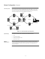
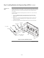
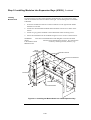
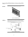
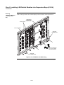
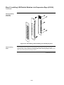
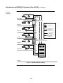
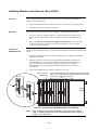
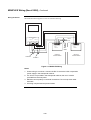
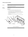
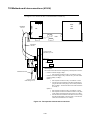
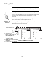
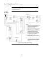
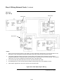
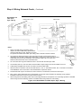
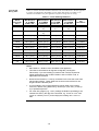
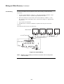
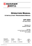
1
Fire 4100U Fire Indicator Panel Fire Alarm System, Installation & Maintenance Australian Australian Installation & Installation Maintenance Manual Manual LT0350 Copyrights and Trademarks 2004 Tyco Safety Products Westminster, Westminster, MA 01441-0001 USA. All specifications and other information shown were current as of document revision date, and are subject to change without notice. Tyco, Simplex, the Simplex logo, MAPNET II, IDNet, TrueAlarm, SmartSync, WALKTEST, MINIPLEX, and TrueAlert are trademarks of Tyco International Services AG or its affiliates in the U.S. and/or other countries. VESDA is a trademark of Vision Products Pty Ltd. Simplex fire alarm technology is protected by the following U.S. Patent Numbers: TrueAlarm analog smoke detection: 5,155,468; 5,173,683 and 5,543,777. IDNet and MAPNET II addressable communications; 4,796,025. TrueAlert addressable notification; 6,313,744 and 6,426,697. SmartSync horn/strobe control; 6,281,789. Approvals Australian Standard AS4428.1 SSL Listing Number afp1682 Manufacture The 4100U is a Fire Alarm manufactured by Tyco Safety Products for: Tyco Services Fire & Safety 47 Gilby Road Notting Hill VIC 3168 AUSTRALIA Phone : (03) 9538-7220 Fax : (03) 9538-7255 Product / Site Name Serial # Manufacture Date i Non-Disclosure Agreement Tyco (THE COMPANY) and the User of this/these document(s) desire to share proprietary technical information concerning electronic systems. For this reason the company is disclosing to the User information in the form of this/these document(s). In as much as the company considers this information to be proprietary and desires that it be maintained in confidence, it is hereby agreed by the User that such information shall be maintained in confidence by the User for a period of TEN YEARS after the issue date and only be used for the purpose for which it was supplied. During this period, the User shall not divulge such information to any third party without the prior written consent of the company and shall take reasonable efforts to prevent any unauthorised disclosure by its employees. However, the User shall not be required to keep such information in confidence if it was in their possession prior to its receipt from the company; if it is or becomes public knowledge without the fault of the User; or the information becomes available on an unrestricted basis from a third party having a legal right to disclose such information. The User's receipt and retention of this information constitutes acceptance of these terms. This information is copyright and shall not be reproduced in any form whatsoever. End User Liability Disclaimer The 4100U Fire Indicator Panel provides a configuration programming facility, which may be accessed via a programming computer using a “dongle”. Because this programming facility allows the user to define in detail the operation of the 4100U System being customised, changes may be made by the user that prevent this installation from meeting statutory requirements. The Company, therefore cannot accept any responsibility as to the suitability of the functions generated by the user using this programming facility. ii Model Number & Firmware Revision This manual applies to product with the following: Model number : 4100U Firmware revision : 11.08 and on Document Document Name : LT0350 4100U Installation & Maintenance Manual Cross Reference : 574-848 4100U Installation Manual (USA) Issue : 1.0-G 14 May, 2004 Amendment Log 14 May, 2004 Issue 1.0.6 Original based on 574-848 Rev G iii Cautions, Warnings, and Regulatory Information READ AND SAVE THESE INSTRUCTIONS. Follow the instructions in this installation manual. These instructions must be followed to avoid damage to this product and associated equipment. Product operation and reliability depends upon proper installation. DO NOT INSTALL ANY SIMPLEX® PRODUCT THAT APPEARS DAMAGED. Upon unpacking your Simplex product, inspect the contents of the carton for shipping damage. If damage is apparent, immediately file a claim with the carrier and notify your Simplex product supplier. SAFETY HAZARD - The 4100U CPU Card includes a lithium battery. There is danger of explosion if the battery is incorrectly replaced. Replace only with the same or equivalent type recommended by the manufacturer. Dispose of used batteries according to the manufacturer’s instructions. ELECTRICAL HAZARD - Disconnect electrical field power when making any internal adjustments or repairs. All repairs should be performed by a representative or authorized agent of your local Simplex product supplier. STATIC HAZARD - Static electricity can damage components. Therefore, handle as follows: • Ground yourself before opening or installing components (use the 553-484 Static Control Kit). • Prior to installation, keep components wrapped in anti-static material at all times. EYE SAFETY HAZARD - Under certain fiber optic application conditions, the optical output of this device may exceed eye safety limits. Do not use magnification (such as a microscope or other focusing equipment) when viewing the output of this device. RADIO FREQUENCY ENERGY - This equipment generates, uses, and can radiate radio frequency energy and if not installed and used in accordance with the instruction manual, may cause interference to radio communications. It has been tested and found to comply with the limits defined in AS4428.0-1997 and Amendment 1 : 2002. SYSTEM REACCEPTANCE TEST AFTER SOFTWARE CHANGES - To ensure proper system operation, this product must be tested in accordance with AS1670 after any programming operation or change in site-specific software. Reacceptance testing is required after any change, addition or deletion of system components, or after any modification, repair or adjustment to system hardware or wiring. All components, circuits, system operations, or software functions,known to be affected by a change must be 100% tested. In addition, to ensure that other operations are not inadvertently affected, at least 10% of initiating devices that are not directly affected by the change, up to a maximum of 50 devices, should also be tested and proper system operation verified. IMPORTANT: Verify 4100U System Programmer, Executive, and Slave Software compatibility when installing or replacing system components. Refer to Solution Bulletin SB01014 for compatibility information. iv Table of Contents Copyrights and Trademarks ................................................................................ i Approvals............................................................................................................. i Manufacture......................................................................................................... i Product / Site ....................................................................................................... i Non-Disclosure Agreement .................................................................................ii End User Liability Disclaimer...............................................................................ii Model Number & Firmware Revision..................................................................iii Document ...........................................................................................................iii Amendment Log .................................................................................................iii Cautions, Warnings, and Regulatory Information...............................................iv Table of Contents ............................................................................................... v List of Figures ...................................................................................................xiv List of Tables .....................................................................................................xv Chapter 1 Introduction to the 4100U Fire Alarm System ........ 1-1 Introduction .................................................................................................. 1-1 In this Chapter ............................................................................................. 1-1 System Configurations .................................................................................... 1-2 Overview...................................................................................................... 1-2 Standalone Configuration ................................................................................ 1-3 Overview...................................................................................................... 1-3 System Design............................................................................................. 1-3 MINIPLEX Configuration ................................................................................. 1-4 Overview...................................................................................................... 1-4 System Design............................................................................................. 1-4 RUI Communication..................................................................................... 1-5 Network Configuration ..................................................................................... 1-6 Overview...................................................................................................... 1-6 Hub and Star Configurations ....................................................................... 1-6 Connecting Loops........................................................................................ 1-7 System Design............................................................................................. 1-7 Network Communication.............................................................................. 1-7 4100 PIDs (Non-4100U) .................................................................................. 1-8 Annunciation Modules ................................................................................. 1-8 4100U Cabinet Part Identification Numbers (PIDs)......................................... 1-9 Overview...................................................................................................... 1-9 4100U Cabinets ........................................................................................... 1-9 v 4100U PIDs ..................................................................................................... 1-9 Overview...................................................................................................... 1-9 Assemblies, Cards & & Modules ................................................................. 1-9 Kits ............................................................................................................. 1-10 Labels ........................................................................................................1-10 Looms ........................................................................................................1-10 Chapter 2 Installing 4100U FACP Components ....................... 2-1 Introduction .................................................................................................. 2-1 In this Chapter ............................................................................................. 2-1 Introduction to FACPs (4100U) ....................................................................... 2-2 Overview...................................................................................................... 2-2 CPU Bay ...................................................................................................... 2-2 Master Motherboard .................................................................................... 2-3 Master Controller Daughter Card ................................................................ 2-4 Master Controller Daughter Card LEDs....................................................... 2-5 Operator Interface........................................................................................ 2-6 Additional CPU Bay Modules ..................................................................... 2-6 Expansion Bays ........................................................................................... 2-6 System Power Supply (SPS) ....................................................................... 2-7 System Power.............................................................................................. 2-8 The Power Distribution Interface (PDI)........................................................ 2-8 Step 1. Mounting Cabinets (4100U) ................................................................ 2-9 Overview...................................................................................................... 2-9 Step 2. Mounting Card Bays to Cabinets (4100U) .......................................... 2-9 Overview...................................................................................................... 2-9 Step 3. Configuring Cards (4100U) ............................................................... 2-10 Overview.................................................................................................... 2-10 Master Motherboard Configuration............................................................ 2-10 Master Controller Daughter Card Configuration........................................ 2-10 SPS Configuration ..................................................................................... 2-10 PDI Configuration ...................................................................................... 2-11 Configuring Other Cards............................................................................ 2-11 Step 4. Interconnecting Modules and Bays................................................... 2-11 Overview.................................................................................................... 2-11 Guidelines.................................................................................................. 2-11 Card Interconnections in the CPU Bay...................................................... 2-12 Card Interconnections Within Expansion Bays ......................................... 2-12 Basic Bay-To-Bay Interconnections .......................................................... 2-12 Connecting to Motherboards ..................................................................... 2-13 Step 5. Installing Modules into Expansion Bays (4100U) ............................. 2-15 Overview.................................................................................................... 2-15 Placement Guidelines................................................................................ 2-15 Installing 4” X 5” Cards .............................................................................. 2-18 vi Step 6. Installing LED/Switch Modules into Expansion Bays (4100U).......... 2-20 Overview.................................................................................................... 2-20 The LED/Switch User Interface ................................................................. 2-21 LED/Switch Controller Card.......................................................................2-21 LED/Switch Modules.................................................................................. 2-22 Configuring the LED/Switch Controller Card ............................................. 2-22 Activating the Communication Loss Feature............................................. 2-22 Mounting LED/Switch Modules to the Expansion Bay .............................. 2-23 Mounting the Controller Card Assembly....................................................2-24 Changing Display Card LEDs....................................................................2-24 Interconnecting Cards................................................................................ 2-25 Wiring Instructions ..................................................................................... 2-26 The Terminal Block Utility Module (4100U)................................................... 2-27 Overview.................................................................................................... 2-27 Mounting to the Electronics Bay ................................................................ 2-27 Chapter 3 Installing 4100 MINIPLEX Components (Non-4100U) ................................................... 3-29 Introduction ................................................................................................ 3-29 In this Chapter ........................................................................................... 3-29 Introduction to MINIPLEX Systems (Non-4100U) ......................................... 3-30 Overview.................................................................................................... 3-30 MINIPLEX System Components (Non-4100U) .............................................3-32 Overview.................................................................................................... 3-32 The RUI Card............................................................................................. 3-32 Transponder Cabinets ............................................................................... 3-32 The Remote Interface Card (RIC) ............................................................. 3-33 MINIPLEX System Guidelines (Non-4100U).................................................3-34 Overview.................................................................................................... 3-34 Guidelines.................................................................................................. 3-34 Installing Modules into Cabinets (Non-4100U).............................................. 3-35 Overview.................................................................................................... 3-35 Guidelines.................................................................................................. 3-35 Installing the RUI Motherboard................................................................. 3-35 Installing the RIC II Motherboard............................................................... 3-36 Connecting the 733-525 Harness............................................................. 3-37 MINIPLEX Wiring (Non-4100U)..................................................................... 3-39 Overview.................................................................................................... 3-39 Wiring Configurations ................................................................................ 3-39 Class A Wiring ........................................................................................... 3-39 Class B Wiring ........................................................................................... 3-39 Wiring Illustration ....................................................................................... 3-40 Chapter 4 Installing 4100U MINIPLEX Components ................ 4-1 Introduction .................................................................................................. 4-1 In this Chapter ............................................................................................. 4-1 Introduction to MINIPLEX Transponders (4100U)........................................... 4-2 Overview...................................................................................................... 4-2 Transponder Cabinets ................................................................................. 4-2 Transponder Interface Cards (TICs)............................................................ 4-2 Basic TICs ................................................................................................... 4-2 The Local Mode TIC (Not currently available in Australia). ......................... 4-3 TIC Illustrations............................................................................................ 4-4 vii Local Mode Specifications ........................................................................... 4-5 LEDs ............................................................................................................4-6 Card Specifications...................................................................................... 4-6 MINIPLEX System Guidelines (4100U)........................................................... 4-7 Overview...................................................................................................... 4-7 Guidelines.................................................................................................... 4-7 Configuring Cards (4100U).............................................................................. 4-8 Overview...................................................................................................... 4-8 CPU Motherboard DIP Switch ..................................................................... 4-8 TIC Configuration......................................................................................... 4-8 Configuring Other Cards.............................................................................. 4-8 TIC/Riser Mounting (4100U)............................................................................ 4-9 Overview...................................................................................................... 4-9 Mounting Instructions................................................................................... 4-9 TIC/Motherboard Interconnections (4100U).................................................. 4-10 RUI Wiring (4100U) .......................................................................................4-11 Overview.................................................................................................... 4-11 Wiring Configurations ................................................................................ 4-11 Chapter 5 Networking ................................................................ 5-1 Introduction .................................................................................................. 5-1 In this Chapter ............................................................................................. 5-1 Getting Started................................................................................................. 5-2 Overview...................................................................................................... 5-2 Introduction to the 4100 Network Interface Card (NIC) ................................... 5-3 Overview...................................................................................................... 5-3 Network Module Illustrations ....................................................................... 5-4 NIC Card LED Indications............................................................................ 5-4 NIC Motherboards ....................................................................................... 5-5 NIC Media Cards ......................................................................................... 5-6 Requirements and Limitations ..................................................................... 5-7 Step 1. Configuring Network Cards ................................................................. 5-7 Overview...................................................................................................... 5-7 Motherboard Jumper Settings .................................................................... 5-7 NIC Card Address Setting .......................................................................... 5-7 NIC Card Jumper Settings.......................................................................... 5-8 Wired Media Card Jumper Settings............................................................ 5-8 Step 2. Mounting Media Cards to the NIC....................................................... 5-9 Overview...................................................................................................... 5-9 Media Card Mounting .................................................................................. 5-9 Step 3. Mounting Network Cards................................................................... 5-10 Step 4. Wiring Network Cards ....................................................................... 5-11 Overview.................................................................................................... 5-11 Wiring Guidelines....................................................................................... 5-11 Wiring Distances........................................................................................ 5-12 Related Documentation ............................................................................. 5-12 Fiber-Optic Wiring...................................................................................... 5-13 Fiber Optic Connection Types ...................................................................5-13 4190-9010 Coupler Requirements ............................................................ 5-14 Wiring with the Wired Media Card ............................................................. 5-15 viii Wiring Illustrations ..................................................................................... 5-17 Wired Media, Style 7 Wiring .....................................................................5-17 Fiber Optic, Style 7 Wiring ........................................................................ 5-18 Wired Media and Fiber Optic, Style 7 Wiring............................................ 5-19 Chapter 6 The System Power Supply & Alarm Relay Card..... 6-1 Introduction .................................................................................................. 6-1 In this Chapter ............................................................................................. 6-1 SPS Specifications .......................................................................................... 6-2 Input/Output/BatterySpecifications .............................................................. 6-2 SPS Current Consumption .......................................................................... 6-3 Environmental Requirements ...................................................................... 6-4 SPS Configuration ........................................................................................... 6-4 Overview...................................................................................................... 6-4 Jumper Settings........................................................................................... 6-4 Setting the Device Address ......................................................................... 6-4 Adjusting Voltages ....................................................................................... 6-4 SPS LED Indications ....................................................................................... 6-5 LEDs ............................................................................................................6-5 Troubleshooting on SPS.................................................................................. 6-6 Overview...................................................................................................... 6-6 IDNet Power Monitor Trouble ..................................................................... 6-6 Extra Device ................................................................................................ 6-6 Class A Trouble ........................................................................................... 6-6 Earth Fault Search....................................................................................... 6-6 Short Circuit ................................................................................................. 6-6 Channel Fail................................................................................................. 6-6 No Answer/ Bad Answer.............................................................................. 6-6 Output Abnormal.......................................................................................... 6-6 The Alarm Relay Card ..................................................................................... 6-7 Overview...................................................................................................... 6-7 Mounting ...................................................................................................... 6-7 Configuration ............................................................................................... 6-8 Notes............................................................................................................ 6-8 Warning ....................................................................................................... 6-8 Specification ................................................................................................ 6-8 Chapter 7 SPS Field Wiring (4100U) ......................................... 7-1 Introduction .................................................................................................. 7-1 In this Chapter ............................................................................................. 7-1 General Field Wiring Guidelines...................................................................... 7-2 General Guidelines ...................................................................................... 7-2 SPS NAC Field Wiring Guidelines................................................................... 7-3 Overview...................................................................................................... 7-3 Guidelines.................................................................................................... 7-3 Class A NAC Wiring..................................................................................... 7-4 Class B NAC Wiring..................................................................................... 7-5 Power Supply Wiring Distances ...................................................................... 7-5 Overview...................................................................................................... 7-5 Class A NAC Wiring Table ......................................................................... 7-6 Class B NAC Wiring Table ......................................................................... 7-7 ix SPS Auxiliary Power Wiring ............................................................................ 7-8 Overview...................................................................................................... 7-8 Guidelines.................................................................................................... 7-8 Wiring........................................................................................................... 7-9 SPS Relay Wiring ..........................................................................................7-10 Overview.................................................................................................... 7-10 Aux 1 Relay ............................................................................................... 7-10 Alarm Relay Card ...................................................................................... 7-10 Relays ........................................................................................................ 7-11 SPS IDNet Wiring ..........................................................................................7-12 Overview.................................................................................................... 7-12 IDNet Wiring .............................................................................................. 7-12 Guidelines.................................................................................................. 7-12 Class A Wiring ........................................................................................... 7-13 Class B Wiring ........................................................................................... 7-14 Chapter 8 Installing 4100U IDNet & 4100MXP Cards ............... 8-1 Introduction .................................................................................................. 8-1 In this Chapter ............................................................................................. 8-1 The IDNet Card................................................................................................ 8-2 Overview...................................................................................................... 8-2 LEDs ............................................................................................................8-3 Specifications............................................................................................... 8-3 Installing the IDNet Card onto the PDI ............................................................ 8-4 Overview...................................................................................................... 8-4 Installing the ID-Net into a 4100 Card Bay ...................................................... 8-5 Overview...................................................................................................... 8-5 Configuring the Card ....................................................................................... 8-6 Overview...................................................................................................... 8-6 Setting the Shield Tie Point ......................................................................... 8-6 Setting the Address ..................................................................................... 8-6 Wiring to IDNet Devices .................................................................................. 8-7 Overview...................................................................................................... 8-7 Guidelines.................................................................................................... 8-7 Notes............................................................................................................ 8-8 Class A Wiring ............................................................................................. 8-8 Class B Wiring ............................................................................................. 8-9 Troubleshooting on IDNet.............................................................................. 8-10 Overview.................................................................................................... 8-10 IDNet Power Monitor Trouble ................................................................... 8-10 Extra Device .............................................................................................. 8-10 Class A Trouble ......................................................................................... 8-10 Earth Fault Search..................................................................................... 8-10 Short Circuit ............................................................................................... 8-10 Channel Fail............................................................................................... 8-10 No Answer ................................................................................................. 8-10 Bad Answer ............................................................................................... 8-10 Output Abnormal........................................................................................ 8-10 The 4100MXP................................................................................................ 8-11 Introduction ................................................................................................ 8-11 Power Connection ..................................................................................... 8-11 x Chapter 9 PC Software Connections ........................................ 9-1 Introduction .................................................................................................. 9-1 In this Chapter ............................................................................................. 9-1 Software Modes............................................................................................... 9-2 Overview...................................................................................................... 9-2 Software Modes........................................................................................... 9-2 Chapter 10 Australian Version Specifics................................ 10-1 Introduction ................................................................................................ 10-1 In this Chapter ........................................................................................... 10-1 Summary Of Australian Version Specifics..................................................... 10-2 Overview.................................................................................................... 10-2 AS4428 Requirements...............................................................................10-2 Australian Panel Format ................................................................................ 10-3 Overview.................................................................................................... 10-3 Australian / USA Differences ..................................................................... 10-3 4100U/4100A Differences.......................................................................... 10-3 4100U Fan Control Module ........................................................................... 10-4 Overview.................................................................................................... 10-4 Labeling ..................................................................................................... 10-4 Mounting & Connection ............................................................................. 10-4 Programming ............................................................................................. 10-4 Brigade Interfaces ......................................................................................... 10-6 Overview.................................................................................................... 10-6 Format........................................................................................................ 10-6 Applications ............................................................................................... 10-6 Chapter 11 Installation Checklist, Commissioning & Maintenance ............................................... 11-1 Introduction ................................................................................................ 11-1 In this Chapter ........................................................................................... 11-1 Installation Checklist...................................................................................... 11-2 Overview.................................................................................................... 11-2 Alignment & Adjustment ................................................................................ 11-3 Overview.................................................................................................... 11-3 Power Up & Placing into Operation ............................................................... 11-4 Maintenance .................................................................................................. 11-5 xi Appendix A The Device Configuration DIP Switch..................A-1 Overview......................................................................................................A-1 Appendix B Programming Requirements ................................B-1 Introduction ..................................................................................................B-1 In this Chapter .............................................................................................B-1 Required Features .......................................................................................B-1 Notes............................................................................................................B-1 Appendix C Checking System Wiring.......................................C-1 Overview..................................................................................................... C-1 Using the Volt/ Ohm Meter ........................................................................ C-1 Meter Readings .......................................................................................... C-2 Appendix D Earth Fault Detection.............................................D-1 Overview..................................................................................................... D-1 General Guidelines ......................................................................................... D-2 Earth Fault Searching from the Front Panel................................................... D-3 Overview..................................................................................................... D-3 Access Level Selection............................................................................... D-3 Starting the Earth Fault Search .................................................................. D-3 Search Option A: Select Location............................................................... D-4 Search Option B: Select Channel.............................................................. D-5 Search Option C: Last Search Result........................................................ D-5 Completing the Search ............................................................................... D-5 Search Results ............................................................................................... D-6 Overview..................................................................................................... D-6 Non-Point Faults ......................................................................................... D-6 Point Faults................................................................................................. D-6 Fault Not Found .......................................................................................... D-7 No Fault ...................................................................................................... D-7 Result Not Available ................................................................................... D-7 Earth Fault Search Example........................................................................... D-8 Appendix E Related Documentation.........................................E-1 Appendix F Compatible Actuating Devices ............................. F-1 Introduction ..................................................................................................F-1 In this Chapter .............................................................................................F-1 List of Approved Devices.................................................................................F-1 Compatible Detectors, IDNET .........................................................................F-4 Compatible Addressable Field Devices, IDNet ...............................................F-5 xii Appendix G Compatible Batteries............................................ G-1 Appendix H 4100U Specifications.............................................H-1 General ....................................................................................................... H-1 Fuses .......................................................................................................... H-1 Firmware Features...................................................................................... H-1 Voltage & Current Ratings of Modules & Assemblies .................................... H-2 Appendix I Power Supply & Battery Capacity Calculations ... I-1 Power Supply................................................................................................ I-1 Battery Capacity ........................................................................................... I-1 Appendix J Cable Characteristics............................................. J-1 IDNet............................................................................................................ J-1 4100 MAPNET II.......................................................................................... J-1 NETWORK .................................................................................................. J-1 Appendix K List of Drawings.....................................................K-1 xiii List of Figures Figure 1-1. Figure 1-2. Figure 1-3. Figure 1-4. Figure 2-1. Figure 2-2. Figure 2-3. Figure 2-4. Figure 2-5. Figure 2-6. Figure 2-7. Figure 2-8. Figure 2-9. Figure 2-10. Figure 2-11. Figure 2-12. Figure 2-13. Figure 2-14. Figure 2-15. Figure 2-16. Figure 2-17. Figure 2-18. Figure 2-19. Figure 2-20. Figure 3-1. Figure 3-2. Figure 3-3. Figure 3-4. Figure 3-5. Figure 3-6. Figure 3-7. Figure 4-1. Figure 4-2. Figure 4-3. Figure 4-5. Figure 5-1. Figure 5-2. Figure 5-3. Figure 5-4. Figure 5-5. Figure 5-6. Figure 5-7. Figure 5-8. Figure 5-9. Figure 5-10. Figure 5-11. Figure 5-12. Figure 5-13. Figure 5-14. Figure 6-1. Figure 7-1. Figure 7-2. Figure 7-3. Figure 7-4. Figure 7-5. Figure 7-6. Figure 7-7. Figure 8-1. Standalone 4100U System ........................................................... 3 MINIPLEX 4100U System ............................................................ 5 Hub/Ring Configuration ................................................................ 6 Interconnected Loop Configuration............................................... 7 Master (CPU) Motherboard (566-227)....................................... 2-3 Master Controller Daughter Card (566-149).............................. 2-4 Operator Interface...................................................................... 2-6 System Power Supply................................................................ 2-7 The Power Distribution Interface (PDI)...................................... 2-8 Bracket Mounting ....................................................................... 2-9 Bay-to-Bay Interconnections.................................................... 2-13 Power and Communication Wiring for Motherboards.............. 2-14 Expansion Bay 4”x 5” Card Placement.................................... 2-15 Expansion Bay Motherboard Placement ................................. 2-16 Mixed Module Placement ........................................................2-17 Slave Card/PDI Connection..................................................... 2-18 Installing the Motherboard in a 4100U Expansion Bay............ 2-19 LED/Switch Modules................................................................ 2-21 LED/Switch Controller.............................................................. 2-21 LED/Switch Card Mounting...................................................... 2-23 Controller Card Mounting......................................................... 2-24 Assembling / Disassembling the LED Display Card ................ 2-25 LED/Switch Controller Wiring .................................................. 2-26 Terminal Block Utility Module Mounting .................................. 2-27 MINIPLEX System Design....................................................... 3-31 The Remote Unit Interface Card.............................................. 3-32 The RIC II Card........................................................................3-33 Installing the RUI Motherboard in the CPU Bay ...................... 3-35 Installing the RIC II Motherboard into a 4100 Expansion Bay. 3-36 Power and Communication Wiring for the Transponder Cabinet (4100) ......................................................................... 3-38 MINIPLEX Wiring .....................................................................3-40 Transponder Interface Cards..................................................... 4-4 TIC Mounting ............................................................................. 4-9 Transponder Cabinet Interconnections.................................... 4-10 TIC Wiring to the Host Panel ................................................... 4-11 4100-6014 Network Interface Card............................................ 5-4 UT Motherboard with City Connection (565-274) ...................... 5-5 UT Motherboard without City Connection (565-275) ................. 5-5 The 4100/4120-0143 Fiber-Optic Media Card........................... 5-6 The 4100/4120-0142 Wired Media Card ................................... 5-6 Media Card Mounting ................................................................ 5-9 Installing the Daughter Card .................................................... 5-10 The Transient Suppressor ....................................................... 5-12 Fiber Wiring.............................................................................. 5-13 Coupler Wiring ......................................................................... 5-15 Wired Media Interconnections Between 4100U Motherboards5-16 Wired Media, Style 7 Wiring .................................................... 5-17 Fiber Optic, Style 7 Wiring ....................................................... 5-18 Wired Media and Fiber Optic, Style 7 Wiring........................... 5-19 The Alarm Relay Card ............................................................... 6-7 The Ferrite Bead (SX0005)........................................................ 7-2 Class A NAC Wiring................................................................... 7-4 Class B Wiring ........................................................................... 7-5 Auxiliary Power Wiring............................................................... 7-9 Auxiliary Relay & Alarm Relay Card Relays ............................ 7-11 Class A Wiring ......................................................................... 7-13 Class B Wiring ......................................................................... 7-14 The IDNet Card.......................................................................... 8-2 xiv Figure 8-2. Figure 8-3. Figure 8-4. Figure 8-5. Figure 8-6. Figure 9-1. Figure 9-2. Figure 9-3. Figure 10-1. Figure D-1. Figure G-1. Mounting onto the Power Distribution Interface......................... 8-4 Mounting into 4100 (legacy) Bay ............................................... 8-5 DIP Switch SW1......................................................................... 8-6 Class A Wiring ........................................................................... 8-8 Class B Wiring ........................................................................... 8-9 Service and Diagnostic Interface ............................................... 9-2 Data Transfer Interface.............................................................. 9-2 Bootloader Interface .................................................................. 9-3 Fan Control Module ................................................................. 10-5 Volt/Ohm Meter Readings ........................................................D-1 Earth Fault Search Example.....................................................G-8 List of Tables Table 2-1 Table 5-1 Table 5-2 Table 5-3 Table 5-4 Table 5-5 Table 6-1 Table 6-2 Table 6-3 Table 7-1 Table 7-2 Table 8-1 Table 8-2 Table 10-1 Table 10-2 Table A-1 Table C-1 Master Controller LEDs 1 through 4 ............................................. 2-1 4100 NIC & Media Cards – Electrical and Environmental Specifications................................................................................ 5-7 Wiring Distances......................................................................... 5-12 Dual Fiber Optic Cable Communications Distance Examples ... 5-14 Single Fiber Optic Cable Communications Distance Examples using 4190-9010 Bi-Directional Couplers .................. 5-14 566-227 CPU Motherboard Wired Media Connections .............. 5-16 SPS Input and Output Specifications ........................................... 6-2 SPS Current Specifications .......................................................... 6-3 Alarm Relay Card Jumper Positions............................................. 6-8 Class A Wiring Distances ............................................................. 7-6 Class B Wiring Distances ............................................................. 7-7 IDNet Specifications ..................................................................... 8-3 Cable Run Lengths .......................................................................8-8 Switch/LED Format.....................................................................10-4 Switch Status ..............................................................................10-4 Card Addresses ............................................................................A-2 Acceptable Zone and Signal Circuit Meter Readings.................. C-2 xv xvi Chapter 1 Introduction to the 4100U Fire Alarm System Introduction The 4100/4100U is an expandable fire alarm system that can be used as a standalone system with one host panel, or as a wide-ranging system with several remote cabinets, with or without multiple host panels. This chapter is an overview of standalone, MINIPLEX, and network 4100 system concepts. In this Chapter Refer to the page number listed in this table for information on a specific topic. Topic See Page # System Configurations 1-2 Standalone Configuration 1-3 1-4 MINIPLEX Configuration Network Configuration 1-6 4100 PIDs (Non-4100U) 1-8 4100U Cabinet Part Identification Numbers (PIDs) 1-9 4100U PIDs 1-9 1-1 System Configurations Overview The 4100U is available as a standalone system with one host panel, or as an expansive system with several remote back boxes, with or without multiple host panels. The type of configuration used depends on the size of the site into which it is being installed. The following types of configurations are offered: Standalone. Comprised of one FACP and its assorted warning devices, initiating devices, and signaling line circuit devices. MINIPLEX. A standalone system plus remote transponder cabinets, which allow for additional slave modules to be used. Typically used for multi-level buildings and small multi-building applications. Network. A multi-FACP system connected by network cards. Each panel maintains the status and control of its own circuit points while monitoring and controlling activity at other locations. Network nodes may perform similar tasks, or may be dedicated to specific functions. This chapter outlines the fundamental concepts of each configuration. 1-2 Standalone Configuration Overview The standalone version of the 4100U is used for smaller or single-building applications. A standalone system is ideally placed into a small building that requires a limited number of notification appliances and initiating devices. If a small building is being expanded, or if other buildings are being constructed in the same general area (as in a campus application), the standalone 4100U can be expanded into one of the larger systems described later. System Design The standalone 4100U uses one FACP (one, two, or three bays) containing the following: • CPU • System Power Supply for the 4100U (Universal Power Supply for the 4100) • Optional slave cards All appliances and devices are connected to that one FACP, as shown in Figure 1-1. To additional IDNET devices, up to 250 total to Device O 1 Smoke sensor with base 1 2 3 4 5 6 7 A D D R E S S C O 51 963 2 3 4 5 6 Supervised IAM Remote line powered isolator FIRE ALARM PULL DOWN Addressable station 5133IN2121IN2121 90ST9090- SI 9-33ST90AL9191AL9191 M 57BA ..I6361. 5755 PL UD NS .04 .04 IN.01 .09 EX RA TR ST2A TI TE M 28UC RU . C. E VD 1 2 3 4 5 AD DR ES S CO I/O Module Thermal sensor with base PULL TO OPEN DOOR OPERATO SYSTEM IS NORMAL 12:35:15 am MON 29 JAN 96 SYST ALA SUPERVI TROU SILEN O INTERFAC PANEL ALA TB AC ACKNO 4100 EMERGENCY INSTRUCTI ONS ALARM OR TROUBLE - SYSTEM INDICATOR TO - PRESS "ACK" LOCATED - REPEAT OPERATION UNTIL TO SILENCE - PRESS "ALARM RESTORE SYSTEM -TOPRESS - PRESS "ACK" TO FIRE ALARM CONTROL Figure 1-1. Standalone 4100U System 1-3 MINIPLEX Configuration Overview The MINIPLEX version of the 4100 Fire Alarm System, which is designed for moderately larger applications than the standalone configuration, allows up to 1000 monitor and/or control points and 2000 annunciator points to be controlled by a single FACP. Like the standalone system, only one CPU is used. Remote Unit Interface (RUI) data, and optionally power is distributed from the host panel to remote boxes called transponder cabinets. The exact system design varies, depending on whether the system is a 4100 or a 4100U: System Design • 4100U: Transponder interface cards (TICs), located in transponder cabinets, take the RUI data directly from the CPU motherboard and distribute it to modules nearby, thereby expanding the system’s status from standalone to MINIPLEX. • 4100: Remote interface cards (RICs), located in transponder cabinets, take the RUI data and optionally power from the remote unit interface (RUI) card in the host panel and distribute it to modules nearby, thereby expanding the system’s status from standalone to MINIPLEX. The MINIPLEX 4100 FACP must contain the following: • CPU • System Power Supply for the 4100U (Universal Power Supply for the 4100) • 4100 only (non-4100U): Remote unit interface (RUI) Card • Optional slave cards Each transponder cabinet, meanwhile, must contain a Transponder Interface Card (TIC) and any number of optional slave cards. Continued on next page 1-4 MINIPLEX Configuration, Continued RUI Communication The 4100 internal comms bus may be used to carry data from the CPU in the main cabinet to expansion equipment in a co-located cabinet. 4100 data from the CPU may be routed to remote cabinets (RTUs) in a MINIPLEX system by using the external RUI comms bus. An RUI line, routed from either the CPU Motherboard in the 4100U, or the RUI card in the 4100, allows the data to travel long distances. Once the RUI line terminates at a remote cabinet, the TIC (4100U) or RIC (4100) in that cabinet distributes the CPU’s data to the other modules within the cabinet. Power has to be supplied locally within each RTU, or routed from the main FIP. Figure 1-2, below, outlines this process in a typical MINIPLEX setup. RUI I/F Slave Risers from 4100U to Remote Transponders RUI Slave Slave RUI I/F Slave Slave Slave 9th Floor Transponder Unit 6th Floor Transponder Unit Transponders may be located further apart (within the 2500' limit) as called for by the application requirements. RUI I/F Slave Slave Slave 3rd Floor Transponder Unit Note: Although not shown, nested RUI is supported up to one level deep. 4100U RUI Risers - 4 MAX (same channel) (from CPU Motherboard or Remote Unit Interface Card) Figure 1-2. MINIPLEX 4100U System 1-5 Network Configuration Overview The 4100 can be expanded to a network system by using network interface cards (NICs). When a NIC is installed into a 4100 host panel, it is used to connect to other network nodes. Nodes may consist of other host 4100 panels, or they may be completely different: Graphical Command Centers (GCCs), and Visual Command Centers (VCCs) are all examples of what could be used as nodes. A node is a self-sufficient CPU that controls appliances and devices, which also has the capability of controlling and communicating with other nodes. The network configuration supports two prevalent architectures (or wiring configurations): hub (or ring), or star. A networked system can also use a combination of the two. Hub and Star Configurations The hub configuration consists of a main loop with nodes connected in a radial manner. The star configuration consists of several nodes connected directly to one common node. Physical bridge cards are used for the star configuration. Physical bridges reduce the amount of wire that would otherwise be needed to connect all nodes in a loop, and therefore cut down on system response time. A combination of the two styles is illustrated in Figure 1-3. Ring Topology Graphic Command Center (GCC) Network Display Unit (NDU) Hub Node Physical Bridge Links (Star Topology) Distributed Remote Node Locations Figure 1-3. Hub/Ring Configuration Continued on next page 1-6 Network Configuration, Continued Connecting Loops Network loops can be joined via physical bridge cards. There may be no more than two Style 7 network loops (two hub configurations) connected in tandem. For every two loops that are interconnected (using one physical bridge), there can be a maximum of three physical bridges used in a star configuration. See Figure 1-4. Remote Node Physical Bridge Link Hub Node Remote Loop Hub Node Local Loop Physical Bridge Link Graphic Command Center (GCC) Physical Bridge Link Physical Bridge Link Physical Bridging (Star Configuration) Figure 1-4. Interconnected Loop Configuration System Design Network Communication To be used as a network node, a 4100 panel must contain the following: • CPU • System Power Supply • 4100 Network Interface Card • Optional slave cards Network communication is achieved via 4100-6014 or 4100-6035 Network Interface Cards (NICs). Each network node requires a NIC. Once the FACP is a network node, it may be programmed to be fully in control of other nodes, or to be fully passive, or anywhere in between. 1-7 4100 PIDs (Non-4100U) The following is a list of existing 4100+/A cards and modules that may be used with 4100U. Annunciation Modules • 4100-5004 8 AZF Monitor Zone • 4100-0113 Dual RS232 Modem Interface • 4100-0110 MAPNET 2 Addressable Loop • 4100-3003 8 Relay Module • 4100-4321 6 Supervised Relays • 4100-3024 24 Relay Module • 4100-0302 24 I/O Module • 4100-0111 Quad Isolator Module • 4100-0149 Modular Network Card (required 2 media cards) • 4100-0142 Wired Media Card RS485 • 4100-0143 Fibre Optic Media Card • 4100-0301 LED Switch Controller • 4100-0154 VESDA High Level Interface • 4100-0157A 4100A PSU • 4100-0451 Printer • 4100-0301 64/64 LED/Switch Controller • 4100-0302 24-Point I/O Graphic Interface • 4100-0401 8-LED Display Card (Red LEDs) • 4100-0402 16-Point Display Card (Red/Yellow LEDs) • 4100-0403 8-Switch/8-LED Display Card (Momentary switches; red LEDs) • 4100-0404 8-Switch/16-LED Display Card (Maintained switches; one red and one green LED per switch) • 4100-0405 8-Switch/16-LED Display Card (Maintained switches; one red and one yellow LED per switch) • 4100-0408 8-Switch/8-LED Annunciator Control Switch Module • 4100-0450 Remote Panel LCD 1-8 4100U Cabinet Part Identification Numbers (PIDs) Overview This section lists all cabinet (back box) PIDs for the 4100U Fire Alarm System. 4100U Cabinets Empty cabinets with Doors (Cream Wrinkle)/ Number of bays that can be fitted: Number of bays • ME0447 18U x 210 Rack Cabinet, Window Door : 1-Bay • ME0268 21U x 310 Rack Cabinet, Window Door : 1-Bay • ME0255 28U x 310 Rack Cabinet, Window Door : 2-Bays • ME0257 40U x 310 Rack Cabinet, Window Door : 3-Bays • ME0454 18U x 210 Rack Cabinet, Solid Door : 1-Bay • ME0269 21U x 310 Rack Cabinet, Solid Door : 1-Bay • ME0265 28U x 310 Rack Cabinet, Solid Door : 2-Bays • ME0267 40U x 310 Rack Cabinet, Solid Door : 3-Bays 4100U PIDs Overview This section lists the PIDs that are supported by the 4100U Fire Alarm System. Assemblies, Cards & & Modules The following is a list of assemblies, cards and modules used in 4100U: • 566-084 Power Distribution Interface (ie the back-plane) • 742-516 CPU Motherboard (566-227) • 4100-7151 Master Controller (CPU Card 566-149) • 4100-2300 PDI back- Expansion Bay Assembly (includes the metalwork with the plane) • 4100-6033 and used Alarm Relay Card (566-058. Small card plugged onto the SPS to supply the Brigade I/F relays). • 4100-3101 IDNET Module – 250 pt capacity (566-044) • 4100-1288 64 LED/64 Switch Controller module w/mounting plate • 4100-1289 64 LED/64 Switch Controller module • 4100-1282 8 SW/16 LED red/yellow module • 4100-1287 24 Switch/24 red LED module • 4100-1284 8 Switch 16 red/green LED module • 4100-1281 8 Switch 8 yellow LED module Continued on next page 1-9 4100U PIDs, Continued Kits • 4100-0625 Transponder Interface Card • 4100-0160 Internet Interface Module (566-355). • 4100-9848AU System Power Supply, Australian version. • ME0456 Fan Control Module The following kits are available: • KT0419 A4 Document Holder, Stick-On, 3U High, Grey • KT0446 4100U Expansion Bay • KT0447 Expansion SPS, Bay Mounting • KT0448 Fused DC Distribution Bd, XSPS AU Mounting • KT0450 4100-4100U Upgrade, 19” RAC Mounting • KT0452 IDNet Mounted on 4100 Interface Bracket • KT0468 4100 MBd to 4100U Bay, Mounting Kit • KT0469 A5 Document Holder, Stick-On, 3U High, Grey Brigade Interfaces • KT0199 KT0207 19”, 3U ASE Mounting Bracket, plus ASE FAS Interface Loom • FZ9028 19”, 3U AIU/PPU Mounting Bracket & Loom Labels LB0602 LB0605 526-873 4100-1294 Operator I/F ISO/Test, Card Fan Control Zone Insert Card Slide In Label, LED Switch Module, 1 Sheet of 6 Module Slide In Labels, Panel Set Looms LM0309 LM0310 LM0311 734-008 734-075 SX0039 SX0052 4100U Mains Lead With Filter 4100U Battery Lead Set, 18U-21U (1976-132-1) 4100U Battery Lead Set, 28U-40U (1976-132-2) Harness, Power Comms, 4 Way, 2ft Length Harness, Power Comms, 4 Way, 8ft Length Sw/LED Module Ribbon Cable, 26 Way, 2in Sw/LED Module Ribbon Cable, 26 Way, 6in 1-10 Chapter 2 Installing 4100U FACP Components Introduction 4100U cabinets are available in one-, two-, and three-bay sizes. Each can be equipped with a solid or perspex door. This chapter describes how to mount all types of 4100U cabinets to a wall, and how to mount system card bays into the cabinets, modules to bays, etc. FACPs are assembled to order within the factory. Steps 2 to 6 below are therefore not typically required in the field, but are included in case of in-field system expansion. The section Introduction to FACPs describes the various components that make up the FACP. The assembly drawings 1976-136, 1976-137 are included in the appendix of this manual for reference. In this Chapter Refer to the page number listed in this table for information on a specific topic. Topic See Page # 2-2 Introduction to FACPs (4100U) Step 1. Mounting Cabinets (4100U) 2-9 Step 2. Mounting Card Bays to Cabinets (4100U) 2-9 Step 3. Configuring Cards (4100U) 2-10 Step 4. Interconnecting Modules and Bays 2-11 2-15 Step 5. Installing Modules into Expansion Bays (4100U) Step 6. Installing LED/Switch Modules into Expansion Bays (4100U) 2-20 The Terminal Block Utility Module (4100U) 2-27 2-1 Introduction to FACPs (4100U) Overview 4100U FACPs cabinets contain the CPU, operator interface, system power supply (SPS), backup batteries, and any additional modules that the panel requires. The FACP is the central hub (often referred to as a host panel) of a standalone or MINIPLEX fire alarm system. In a networked system, the FACP can be connected to other system FACPs, so that each host panel is a node on the network. CPU Bay In the standard (USA) version of 4100U the CPU bay contains an SPS, the Master Motherboard with CPU Daughter card, but no PDI to which 4” x 5” cards (e.g. IDNet card) can be fitted. Also, it has the Operator Interface (I/F) on its front, so no switch/LED display modules can be fitted to it. In the Australian version the SPS is fitted to a bracket behind a side-hinged 4U door that has the Operator I/F on it. The Master Motherboard (i.e. CPU Motherboard) is fitted to the right hand side of an expansion bay mounted directly below. This bay has a PDI fitted so can house 4”x 5”cards and Switch/LED Display Modules. Continued on next page 2-2 Introduction to FACPs (4100U), Continued Master Motherboard The 4100U Master motherboard that houses the CPU card is central to the 4100U system. It mounts in the first bay, occupying four inches of space on the right hand side. Neither has a card address DIP switch (the CPU is address 0). NETWORK WIRED MEDIA/ RS-232 TERMINAL BLOCK (TB3) XMIT RTS RCV CTS GND 1 5 RUI TERMINAL BLOCK (TB2) RUI RUI SHLD RUI RUI B+ BA+ A- RUI COMM EARTH SHIELD JUMPER (P9) 5 1 RS-232/NETWORK CARD PORT 1 JUMPER (P10) POWER/COMM TO SYSTEM POWER SUPPLY (P1) RUI CLASS A TROUBLE (LED1) COMMS CONNECTOR TO OPTION MOTHERBOARD (P8) RUI PRIMARY SHORT TROUBLE (LED2) RUI SECONDARY SHORT TROUBLE (LED3) HEADER CONNECTOR TO OPTION MOTHERBOARD (P3) BUS CONNECTOR (J1) (Reserved for future use) CPU DAUGHTER CARD CONNECTOR (J3) POWER CONNECTOR TO OPTION MOTHERBOARD (P7) POWER/COMMS TO ADJACENT BAY (P4) NETWORK DAUGHTER CARD CONNECTOR (J2) POWER/COMMS TO ADJACENT BAY (P5) RS-232/NETWORK CARD PORT 2 JUMPER (P11) POWER/COMMS TO ADJACENT BAY (P6) 1 8 NETWORK WIRED MEDIA/ RS-232 TERMINAL BLOCK (TB1) PIEZO XMIT RTS RCV CTS GND 24C RSRVD Figure 2-1. Master (CPU) Motherboard (566-227) Continued on next page 2-3 Introduction to FACPs (4100U), Continued Master Controller Daughter Card The master controller daughter card mounts onto the master motherboard. The master controller daughter card contains a service port, a direct drive user interface connection, and a port for a service modem. MODEM 2 SERVICE MODEM CONNECTOR (P4) SERVICE PORT COMM JUMPER (P1) LED1 LED2 LED3 CPU BOOTLOADER LEDs (LED1 – LED4) TROUBLE LED (LD5) CONNECTOR TO CPU MOTHERBOARD (P9) BAT ON SERVICE PORT BAT OFF BATTERY BACKUP ON/ OFF JUMPER (P3) SERVICE PORT (P5) DISPLAY DIRECT-DRIVE DISPLAY PORT (P6) CPU CARD BD ASSY 566-149 TROUBLE LED (LED5): OFF: No trouble. FLASHING: CPU has power but the software is failing to hit the watchdog ON: The 5 V is outside the acceptable range WARM START SWITCH (SW1) Figure 2-2. Master Controller Daughter Card (566-149) Continued on next page 2-4 Introduction to FACPs (4100U), Continued Master Controller Daughter Card LEDs The master controller daughter card LEDs indicate Bootloader status as shown in the table below. Table 2-1. Master Controller LEDs 1 through 4 Status Condition LED4 LED3 LED2 LED1 On (0.25s), Off (0.25s) On (0.25s), Off (0.25s) On (0.25s), Off (0.25s) On (0.25s), Off (0.25s) Bad Master CRC or No Master Present On Off Off Off Diagnostic Fail – RAM On Off Off On Diagnostic Fail – Bootloader CRC On Off On Off Downloading Master On Off On On Downloading CFIG On On Off Off Downloading MsgLib On On Off On Downloading BootLoader On On On Off Download Successful On On On On Bootloader Initialization Continued on next page 2-5 Introduction to FACPs (4100U), Continued Operator Interface The operator interface lets a user operate the panel. It provides alarm, trouble, and isolate status alerts, and lets the user review historical logs and perform diagnostics. Figure 2-3. Operator Interface Additional CPU Bay Modules The CPU bay can be equipped with many additional types of modules. The cards listed below are limited to the CPU bay only. 4100-6030 Service Modem Card. CPU mezzanine card. Provides a connection to remote PCs for diagnostics and programming purposes. (Not approved for use in Australia). 4100-6014 Modular Network Interface Card (NIC). A daughter card that mounts to the CPU motherboard. Performs 4100 networking operations. May be installed with the 4100-6056 Wired Media Card and/or the 4100-6057 Fiber Media Card. Expansion Bays An FACP always has the CPU in the first bay, but it may have further expansion bays. Expansion bays contain a variety of additional modules that the system might require. Continued on next page 2-6 Introduction to FACPs (4100U), Continued System Power Supply (SPS) In the USA, a number of variants of power supply are available, e.g. SPS, RPS, XPS, XCharger each with different portions of circuitry (eg NACs, Battery Charger, IDNet) fitted or not fitted. In Australia, only one variant (SPS) is currently available, and it has hardware and software that are specific to Australia. This unit is used as the main power supply, but may also be fitted directly to a card bay as an expansion supply. The system power supply (SPS) is mains powered and has backup batteries that get switched in on mains failure. It is the initial power source for the CPU and the host cabinet. The SPS provides 24V card power to the CPU motherboard and the other cards. It also supplies 24V power on a separate bus to the outputs, e.g. Notification Appliance Circuits (NACs). The SPS also has three on-board NACs that support reverse polarity supervision. It provides an IDNet channel, auxiliary power, an auxiliary relay, and it mounts and drives the Alarm Relay Card. The SPS performs functions such as brownout detect, battery transfer, battery recharge, earth fault detection, and power limiting of outputs. It provides voltage and current information to the CPU card, which can then be displayed at the user interface. IDNET TERMINAL BLOCK (TB1) NAC TERMINAL BLOCK (TB2) POWER/COMM TO NEXT PDI (P6) IDNET SHIELD JUMPER (P2) CITY/RELAY CARD TROUBLE INDICATION JUMPER (P3) POWER/COMM TO CPU MOTHERBOARD (P8) DEVICE ADDRESS SWITCH (SW1) BATTERY CONNECTORS: P4 P5 AUXILIARY RELAY TERMINAL BLOCK (TB4) AUXILIARY POWER TERMINAL BLOCK (TB3) EARTH FAULT MONITOR JUMPER (P1) CITY CARD CONNECTOR (P7) CITY / RELAY CARD MOUNTING AREA AC CONNECTOR (under board) Figure 2-4. System Power Supply Continued on next page 2-7 Introduction to FACPs (4100U), Continued System Power The FACP is powered by the SPS (System Power Supply), which gets its primary power from the AC mains and its secondary power from the backup batteries. The 24Vdc bulk power on the SPS is unregulated, and is divided into three feeds, i.e. 24V Card, 24V Signal, and 24V Aux Power. 24V Card which supplies the cards, and Aux power, which is accessible on screw terminals, are each rated at 2A and protected by a PTC. The 27.3V regulated battery charger is powered from the bulk supply and is switched off during alarm. The batteries only get connected to the bulk supply when the mains supply fails. The charger has two programmable options of rating, 1.4A for 618Ahr (called little-uns), and 3.3A for batteries above 18Ahr (called big-uns). The “heavy” 24V Signal feed is only accessible via the NACs on the SPS, or via a wire harness. IMPORTANT: AC power must be provided to the 4100U from a dedicated branch circuit. The Power Distribution Interface (PDI) In expansion bays, power and data are distributed via the power distribution interface (PDI). The PDI is a wiring board with eight card slots, each of which can accommodate a 4-inch (102 mm) x 5-inch (127 mm) slave card. If motherboards are used, they must be mounted over the PDI using metal standoffs. Standards cards, e.g. IDNet, plugged onto the PDI access only the 24V Card supply. If an XSPS is plugged onto the PDI, then the 24V Signal Bus is also powered. This is required for the 4100MXP which uses card power to power its electronics, but signal power to supply the 40V loop. POWER/COMMS CONNECTORS (P1-P3) 4100 POWER DISTRIBUTION INTERFACE ASSY 566-084 POWER SOURCE JUMPERS (P4, P5) AUDIO INTERFACE CONNECTORS (P6, P7) Figure 2-5. The Power Distribution Interface (PDI) 2-8 Step 1. Mounting Cabinets (4100U) Overview The important aspects of mounting the cabinet are: Access for the operator; Height of displays and controls; Free space for door opening; Cable entry for field wiring. Refer to AS1670 for the height requirement and minimum access requirements. In general, 18U – 28U cabinets will need to be wall mounted. Mounting holes and cabinet dimensions are shown in drawing 1919-22b. Door opening left/right should be specified with the order. The cabinets are symmetrical, top to bottom, so door opening can be swapped by removing the equipment, rotating the cabinet 180°, then re-fitting the equipment. Step 2. Mounting Card Bays to Cabinets (4100U) Overview FACPs are ordered from the factory with bays and cards fitted as per the panel order spreadsheet. Additional mounting bays may be ordered as KT0447 which includes the 19” rac mounting brackets and earth loom. Attach each mounting bracket to the two studs in each front corner to achieve the format shown below. Fit M6 cage nuts to the appropriate 19”rack holes, then attach the bay using M6 countersunk screws. ← Mounting Bracket ← Bay Front Figure 2-6. Bracket Mounting Refer to the assembly drawings in the Appendix. 2-9 Step 3. Configuring Cards (4100U) Overview The CPU, SPS, and all other modules to be mounted in the FACP cabinets must be configured to operate correctly in the system via their DIP switch and jumper ports. This section describes the hardware configuration for the CPU and SPS, since they will always be used in the CPU bay. Master Motherboard Configuration The CPU motherboard must be jumpered as follows: P9 determines whether the RUI SHIELD signal is connected to 24 C or Earth. • Position 1 – 2: SHIELD to 24 C (default). Set to this position unless the system uses a TrueAlert Power Supply. • Position 2 – 3: SHIELD to Earth. Set to this position only if the system uses a TrueAlert Power Supply. Note: Some devices that connect to RUI have inherently grounded shield terminals, in which case 24 C cannot be used. If 24 C is used, a Negative Ground Fault will occur. P10/P11: P10 is associated with Port 1 and P11 is associated with Port 2. P10 and P11 are used to set the CPU motherboard up to be attached to either a network card or a RS232/2120 card. • Position 1 – 2: Network card (NIC) attached to CPU motherboard (default). • Position 2 – 3: RS-232/2120 card attached to CPU motherboard. Master Controller Daughter Card Configuration The master controller daughter card must be jumpered as follows: P1 is used for engineering diagnostics (COMLAB). • Position 1 – 2 : Download or no connection. • Position 2 – 3 : Diagnostic mode. P3 configures the RAM battery as ON or OFF. • Position 1 – 2 : ON. • Position 2 – 3 : OFF. SPS Configuration The SPS must be configured as follows: SW1: Using DIP switch SW1, set the SPS device address. Use the address table in Appendix A. P2: If the SPS IDNet outputs are being used, you may change P2 to configure the IDNet shield connection. • Position 1 – 2 (bottom) : Connects the shield to 0 V (default). • Position 2 – 3 (top) : Connects the shield to earth ground. P3 configures relay 3 on the 4100-6033 Alarm Relay Card. • Position 1 – 2 (top) : Removes fault monitoring on relay 3 (default). • Position 2 – 3 (bottom) : Makes relay 3 activate when there is a fault. P1: Earth connect jumper. • Position 1 – 2 (rhs): Enables Earth fault monitoring. Set to this position unless the system uses a TrueAlert Power Supply under common 0 V. • Position 2 – 3 (lhs): Disables Earth fault monitoring. Set to this position only if the system uses a TrueAlert Power Supply under common 0 V. Continued on next page 2-10 Step 3. Configuring Cards (4100U), Continued PDI Configuration P4/P5: The PDI can be configured to draw its power from different sources via P4 and P5. • To draw power from an XPS on the PDI, set jumpers on P4 and P5 to position 2 – 3. • To draw power from P1 (from the previous PDI or SPS), set jumpers on P4 and P5 to position 1 – 2 (default). • To remove power from the PDI, remove the jumper from P4. Configuring Other Cards Refer to the appropriate installation instructions to configure other cards that are located in CPU and expansion bays. The 4100U ones are included in this manual. Refer to Appendix D for a list of publications. Step 4. Interconnecting Modules and Bays Overview Each card has to be interconnected with every other card in its bay. At the same time, bays in the FACP also have to be connected together. Read this section to ensure that cards and bays are interconnected. Refer also to drawings 1976-136 and 1976-137. Guidelines Review the following guidelines before interconnecting modules and bays. • The SPS provides 24 V power to the CPU motherboard. • The CPU motherboard provides 8 V (3 A capacity) for use by Legacy 4100 slave cards. 24 V card power is routed through the motherboard for slave card use. • 4100 internal comms and power are harnessed to other bays. Do not connect the 8 V at P7 to an 8 V converter on a Goldwing or remote interface card. • 24 V Card power from the SPS is rated at 2 A. • The 4-wire coms and power harness carries only the 24 V Card supply to a PDI, and not the 24V Signal supply. • Some of the wire harnesses supplied with cards are not required. It is recommended to store these spare harnesses in case of future requirements. Continued on next page 2-11 Step 4. Interconnecting Modules and Bays, Continued Card Interconnections in the CPU Bay Card Interconnections Within Expansion Bays Basic Bay-To-Bay Interconnections Use the following directions to connect the CPU to the SPS and other motherboards. 1. Connect P3 on the SPS to P1 on the CPU motherboard using the 8 wire harness with eight-position Molex minifit connector (provided). 2. Make sure the 10 way, right angle header, connector P3 on the CPU is secured to J1 on the next motherboard to the left. Repeat this for the third (leftmost) motherboard, and on if applicable. The power distribution interface (PDI) mounted to the back of each expansion cabinet carries 24V Card power and data to each 4”x 5” card. Refer to “Step 7: Installing Modules into Expansion Bays (4100U)” for instructions on mounting 4”x 5” cards to the PDI. Also bear in mind the following variations: • In a remote expansion cabinet, a transponder interface card (TIC) requires additional interconnections. This occurs in MINIPLEX systems. Refer to Chapter 3. • Regular motherboards require non-PDI interconnections to each other and to the CPU. Refer to “Step 5: Installing Modules into Expansion Bays (4100U).” The 4 wire harness 734-008 is used to carry 24V Card power and coms from bay to bay. Connector P1 on the PDI receives power from the previous PDI or from P6 on the SPS (or alternatively from P7, P8 on the CPU Motherboard). P2 on the PDI is used to carry power and coms to a 64/64 Controller. P3 is used to carry power and coms to the next PDI. Jumpers P4 and P5 on the PDI are set to positions 2-3 (right) to provide card power to the bay only if an XPS is fitted to the PDI. Jumpers P4 and P5 are set to positions 1-2 (left) to provide card power to the bay from P1 on the PDI. Note: Interconnections can become more involved if 4100 motherboards are used. Refer to “Step 5: Installing Modules into Expansion Bays (4100U)” if this is the case. Continued on next page 2-12 Step 4. Interconnecting Modules and Bays, Continued Basic Bay-To-Bay Interconnections (continued) Figure 2-7, below, shows the interconnections between three bays in a host panel. From Previous PDI P1 HARNESS 734-008 4100 POWER DISTRIBUTION INTERFACE ASSY 566-084 P2 P3 P4 P5 P6 P7 P3 P1 4100 POWER DISTRIBUTION INTERFACE ASSY 566-084 P2 P3 P4 P5 P6 P7 Figure 2-7. Bay-to-Bay Interconnections Connecting to Motherboards Panels with motherboards on the left side of the expansion bays require some non-PDI connections. If you need to connect a harness to a motherboard, refer to Figure 2-8 and follow these steps. Make sure to route the power and communication wiring on the left side of the bay. 1. Connect one end of the 733-525 Harness to a motherboard in an adjacent bay. If the adjacent bay is a CPU bay with no additional motherboards, connect the harness to the P8 and P7 connectors of the CPU motherboard. • Insert the harness connector with the blue wire into the P8 connector. Note that the P8 connector has eight pins. Insert the harness connector on either the top four pins or the bottom four pins, not in the middle. • Insert the harness connector with the white wire into the P7 connector. Note that the P7 connector has eight pins. Insert the harness connector on either the top four pins or the bottom four pins, not in the middle. If the adjacent bay is an expansion bay or a CPU bay with additional motherboards, connect the harness to the P2 and P3 connectors of the motherboard installed in the leftmost slot. Connect the harness as follows: • Insert the harness connector with the blue wire into the P2 connector. Note that the P2 connector has eight pins. Insert the harness connector on either the top four pins or the bottom four pins, not in the middle. • Insert the harness connector with the white wire into the P3 connector. Note that the P3 connector has eight pins. Insert the harness connector on either the top four pins or the bottom four pins, not in the middle. Continued on next page 2-13 Step 4. Interconnecting Modules and Bays, Continued Connecting to Motherboards (continued) 2. Connect the other end of the harness to the leftmost motherboard in the next bay, as described below. Make sure to route the wiring on the left side of the bay. • Insert the harness connector with the blue wire into the P2 connector. Note that the P2 connector has eight pins. Insert the harness connector on either the top four pins or the bottom four pins, not in the middle. • Insert the harness connector with the white wire into the P3 connector. Note that the P3 connector has eight pins. Insert the harness connector on either the top four pins or the bottom four pins, not in the middle. 733-525 Harness Connector with Blue Wire Goes to P2 Connector with White Wire Goes to P3 Figure 2-8. Power and Communication Wiring for Motherboards 2-14 Step 5. Installing Modules into Expansion Bays (4100U) Overview This section contains guidelines and instructions on installing 4”x 5” cards and traditional motherboards into 4100U card bays. IMPORTANT: This section applies to aftermarket modules for expansion bays only. If you do not need to install any aftermarket modules at all, and if you have followed Steps 1 through 6, you have completed the panel installation and can apply AC power. Placement Guidelines Refer to the following guidelines before mounting 4” x 5” cards and/or motherboards to an expansion bay. • Each expansion bay assembly includes a chassis, two end supports, one LED/switch frame, and a power distribution interface (PDI) board. • An expansion bay holds up to eight 4” x 5” modules. A double-size module, such as the expansion power supply (XPS), takes up two blocks of space as shown below. The Australian SPS takes up four blocks of space (note, the double sized XPS is not currently available for Australia). • Cards should be added from right to left if an XSPS is fitted. Block A Block C Block E Slots 7 + 8 I/O Wiring I/O Wiring I/O Wiring I/O Wiring 4" (102 mm) x 5" (127 mm) Module 4" (102 mm) x 5" (127 mm) Module 4" (102 mm) x 5" (127 mm) Module Expansion Power Supply Power Distribution Interface (PDI) (XPS) 4" (102 mm) x 5" (127 mm) Module I/O Wiring Block B 4" (102 mm) x 5" (127 mm) Module 4" (102 mm) x 5" (127 mm) Module I/O Wiring I/O Wiring Block D Block F (Note. Australian SPS is 4 slots wide. XPS is not available in Australia.) Figure 2-9. Expansion Bay 4”x 5” Card Placement Continued on next page 2-15 Step 5. Installing Modules into Expansion Bays (4100U), Continued • Up to eight 2” (51 mm) x 11 ½” (292 mm) motherboards can be installed in an expansion bay if no 4”x 5”modules are installed in the bay, and if the pins on the left connector (usually P1) on the leftmost motherboard are removed. Motherboards are mounted on top of the PDI in expansion bays. The data and power that would normally be bussed via the PDI is instead routed across the boards via ribbon cable from one board to the next. • Motherboards should be added from left to right. • Relay motherboards must be the rightmost motherboards. • In the first bay of an FACP, the CPU motherboard is the right most motherboard, and other motherboards are fitted to its left side. • The CPU motherboard generates the 8V supply required for 4100A motherboards. It also has the 4100A style Molex connectors to which a harness can be fitted as per Fig 2-8. Slot 5 Slot 6 4100 Option Bd Slot 4 4100 Option Bd Slot 3 4100 Option Bd This Slot Must Remain Empty Slot 2 4100 Option Bd Slot 1 Slot 7 Slot 8 4100 Option Bd Motherboards can be installed on top of the PDI in expansion bays. The data and power that would normally be bussed via the PDI is instead routed across the boards via ribbon cable from one board to the next. 4100 Option Bd • 4100 Option Bd Placement Guidelines (continued) Power Distribution Interface This slot cannot contain a motherboard unless the pins on P1 (or leftmost pin connector) are removed. Up to eight 2” (51mm) x 11 ½” (292 mm) motherboards can be mounted in an expansion bay. Seven motherboards fit into Slots 2 through 8; the eighth can be added in Slot 1 if its leftpost pins are removed. Figure 2-10. Expansion Bay Motherboard Placement Continued on next page 2-16 Step 5. Installing Modules into Expansion Bays (4100U), Continued As shown in the figure below, motherboards can be installed alongside 4”x 5” cards, if necessary. Slot 2 Slot 3 Slot 4 4100 Option Slot 1 4100 Option • 4100 Option Placement Guidelines (continued) Position Block E 5 Position Slots 7 + 8 7&8 I/O Wiring I/O Wiring 4" (102 mm) x 5" (127 mm) Module Expansion Power Supply PDI (XPS) No Boards Allowed in This Slot 4" (102 mm) x 5" (127 mm) Module I/O Wiring This slot cannot contain a motherboard unless the pins on P1 (or leftmost pin connector) are removed. Position Block F 6 (Note. Australian SPS is 4 slots wide. XPS is not available in Australia.) Figure 2-11. Mixed Module Placement Continued on next page 2-17 Step 5. Installing Modules into Expansion Bays (4100U), Continued Installing 4” X 5” Cards The power distribution interface (PDI) is mounted to the back of each expansion cabinet. The PDI contains slots for up to eight 4”x 5” slave cards. Since the PDI carries power and data across the entire bay, it solves most interconnection issues, especially between 4”x 5” cards. Use the following instructions and the figure below to mount 4”x 5” slave cards to an expansion cabinet. 1. Screw two standoffs and washers to the appropriate holes in the back of the cabinet. These holes must line up with the screw holes in the 4”x 5” card. See Figure 3-24. 2. Plug the 4”x 5” card into the appropriate blind mating connector. Seat the card firmly onto the PDI when installing to ensure complete insertion of the power connector into the PDI. 3. Secure the top of the card to the standoffs with two #6 torx screws and washers. WASHERS STANDOFFS 4”x 5” CARD SCREW RETAINERS #6 SCREWS PDI CONNECTOR (reverse side) PDI Figure 2-12. Slave Card/PDI Connection Continued on next page 2-18 Step 5. Installing Modules into Expansion Bays (4100U), Continued Installing Motherboards Use the following procedure when installing motherboards in an expansion bay. Start with the second slot from the left and fill to the right. The mounting items are available as KT0468. 1. Orient the motherboard with the connector labeled J1 on the right and the header labeled P1 on the left. 2. Attach four metal threaded standoffs and lockwashers into the screw holes on the chassis. 3. Attach two grey plastic standoffs to the motherboard socket mounting screws. 4. Secure the motherboard to the standoffs using four #6 torx screws as shown below. WARNING: Note that a 4100 Motherboard with daughter card cannot be fitted directly behind a 64/64 LED/Switch Controller. The same applies to the modules made on the bay mounting bracket (FA2255), e.g. ME0426 T-Gen. METAL STANDOFFS SCREW HOLES PLASTIC STANDOFFS #6 SCREWS SCREW HOLES LOCKWASHERS Figure 2-13. Installing the Motherboard in a 4100U Expansion Bay 2-19 Step 6. Installing LED/Switch Modules into Expansion Bays (4100U) Overview The LED/switch user interface consists of a variety of modules, mounted to the front of an expansion bay, which are configured via the 4100 Programmer. Each display module contains between 8 and 24 switches and LEDs, each one separately configurable. User interface functionality is driven by the 64/64 LED/Switch Controller Card, which mounts behind two of the display modules (typically in positions 3 and 4). The varieties of modules are as follows: • 4100-1288 LED/Switch Controller Card with mounting plate. • 4100-1289 LED/Switch Controller Card (no mounting plate; mounts on extra space of 4100-1288). • 4100-1280 8-Switch/8-LED Display Card. With red LEDs. • 4100-1281 8-Switch/8-LED Display Card. With yellow LEDs. • 4100-1282 8-Switch/16-LED Display Card. With one red and one yellow LED per switch. • 4100-1283 8-Switch/16-LED Display Card. With two yellow LEDs per switch. • 4100-1284 8-Switch/16-LED Display Card. With one red and one green LED per switch. • 4100-1285 16-Switch/16-LED Display Card. With red LEDs. • 4100-1286 Hands Off Auto (HOA) Switch Display Card. Provides 24 switches and 24 LEDs. The HOA uses an overlay to group every 3 switches together, denoting on, off, and automatic control of smoke control components. For every group of 3 switches, there are 3 LEDs (green-red-green). • 4100-1287 24-Switch/24-LED Display Card. With red LEDs. • 4100-1279 2” Blank display cover module to cover empty front panel space • 4100-1294 Slide-In Label Kit - one per 4100U cabinet • 4100-1276 8-Pluggable LEDs with 8 red LEDs • 4100-1277 16-Pluggable LEDs with alternating red and yellow LEDs • 4100-1278. 16-Switch/16-LED with alternating red and yellow LEDs, one per switch • 4100-1295 Hands Off Auto (HOA) switch display card. Provides 24 switches and 24 red LEDs. • 4100-1296 8-Switch/16 LED Display Card. With one green and one yellow LED per switch. • 4100-9843 Pluggable LED Kit, 8 Yellow LEDs • 4100-9844 Pluggable LED Kit, 8 Green LEDs • 4100-9845 Pluggable LED Kit, 8 Red LEDs • ME0456 Fan Control Module Continued on next page 2-20 Step 6. Installing LED/Switch Modules into Expansion Bays (4100U), Continued The LED/Switch User Interface Below is an illustration of a LED/switch bay from the user’s perspective. Figure 2-14. LED/Switch Modules The LED/switch controller card is a 4100 slave that mounts behind two LED/switch modules. The LED/switch controller handles up to 64 switches and 64 LEDs on the modules and communicates their status to the 4100 CPU. When a button is pressed on a module, the controller acknowledges the signal and reacts according to how that switch was configured via the 4100 Programmer. GND1 LED/SWITCH DISPLAY CONNECTOR (P4; reverse side) COMM LOSS LED (LED1) REMOTE ANNUNCIATOR JUMPER (P1) SW1 1 2 3 4 POWER/COMMS CONNECTORS (P2) (P3) P2 1 LED1 2 COMM LOSS 2 ADDRESS DIP SWITCH (SW1) P3 1 LED/Switch Controller Card 5 P1 6 7 8 Figure 2-15. LED/Switch Controller Continued on next page 2-21 Step 6. Installing LED/Switch Modules into Expansion Bays (4100U), Continued LED/Switch Controller Card, (continued) If more than 64 LEDs or 64 switches are used, a second controller may be installed. LED/Switch Modules All types of modules are mounted to the front of a bay, and are connected to each other via a ribbon cable. Each module operates by the same rules: when a button is pressed, the controller card sends the CPU the information, and the event programmed for that button occurs. Configuring the LED/Switch Controller Card The 64/64 LED/switch controller requires physical configuration, but the LED/Switch modules do not. Configuration consists of setting jumper P1 and setting the device address. Device Address is covered in Appendix A. Activating the Communication Loss Feature If the LED/switch controller is used in a remote annunciator, it can make the LED/Switch modules annunciate a communication loss condition. If communication loss occurs when this setting is activated, LED 1 of the first connected display card illuminates, and the piezo on the LED/switch controller sounds. The indication is silenced via the corresponding switch (switch 1 on the first display card). LED 1. This LED illuminates if communication loss between the controller and the CPU occurs. It is independent of jumper P1 (which configures different communication loss features). Use jumper port P1 to activate or deactivate the communication loss feature. • Position 1 - 2 deactivates the feature (default). • Position 2 - 3 activates the communication loss feature. Continued on next page 2-22 Step 6. Installing LED/Switch Modules into Expansion Bays (4100U), Continued Mounting LED/Switch Modules to the Expansion Bay Refer to the figure below to mount the display cards to the front of the expansion box. #6 UNC NUTS ADDITIONAL LED/SWITCH CONTROLLER LOCKWASHERS GROUND CONNECTION Controller assemblies can only be installed into these two slots GROUND CONNECTION Figure 2-16. LED/Switch Card Mounting Continued on next page 2-23 Step 6. Installing LED/Switch Modules into Expansion Bays (4100U), Continued Mounting the Controller Card Assembly Refer to the figures and instructions below to mount the controller card assembly to the back of one of the LED/switch cards. 4. Use four 322-123 Nuts and four 268-009 Washers to secure the 637-141 Bracket to the inside front of the expansion box. Note that there are only two locations where the bracket can be mounted, as shown in Figure 2-16. 5. Attach the header connector on the back side of the controller (P4) to the connector on the back side of one of the LED/switch modules. 6. Secure the controller card to the board using four #6 screws, as shown in Figure 5. Figure 2-17. Controller Card Mounting WARNING: 4100 mounts a T-Gen. Changing Display Card LEDs The 64/64 Controller Card cannot be mounted directly in front of a Motherboard or a Bay mounting bracket such as one that The 4100-1276 LED display card contains eight red LEDs and the 4100-1277 card contains 16 alternating red/yellow LEDs. The LED colors may be configured differently, as described in this section. Only the following LEDs are to be used to change color configurations. LEDs are available in sets of eight, as follows: • • • 4100-9843 (yellow) 4100-9844 (green) 4100-9845 (red) Continued on next page 2-24 Step 6. Installing LED/Switch Modules into Expansion Bays (4100U), Continued Changing Display Card LEDs, (continued) Figure 2-18. Assembling / Disassembling the LED Display Card Interconnecting Cards User interface wiring consists of connecting the LED/switch controller card to the expansion bay’s power distribution interface (PDI), and connecting display cards to each other. This section describes both procedures. Continued on next page 2-25 Step 6. Installing LED/Switch Modules into Expansion Bays (4100U), Continued Wiring Instructions The following directions are complete instructions on interconnecting display cards and connecting the controller card to a power source. 1. Use Harness 734-008 to connect P2 on the controller card to one of the 4-pin connectors on the PDI. 2. If there are multiple controller cards, use Harness 734-036 to connect P3 on the controller card to P2 on another controller card. 3. Interconnect all LED/switch display cards with the ribbon cables (provided). Connector P1 is the input; connector P2 is the output. TO PDI CONNECTOR OR ANOTHER CONTROLLER CARD HARNESS 734 008 26 - CONDUCTOR RIBBON CABLE P4 LED / SWITCH CONTROLLER (reverse side) IN OUT IN OUT IN HARNESS 734- 036 TO ANOTHER CONTROLLER CARD LED / SWITCH MODULE3 LED / SWITCH MODULE2 Figure 2-19. LED/Switch Controller Wiring 2-26 LED/ SWITCH MODULE1 The Terminal Block Utility Module (4100U) Overview The 4100-0632 Terminal Block Utility Module is an all-purpose terminal block that mounts to an expansion bay, above or below the power distribution interface (PDI). Each module utilizes one block of mounting space. The terminal block utility module has two 16-position terminal blocks that accept up to a maximum of 12 AWG (3.309 mm2) wire. Mounting to the Electronics Bay Follow the directions below to mount the terminal block utility module to the electronics bay. 1. Align the terminal block utility module to any two compatible screw holes on the electronics bay. Position the higher terminal block towards the middle of the bay. There are eight possible locations: four above and four below the PDI. Refer to the figure, below. 2. Secure the terminal block utility module to the electronics bay with two #6 screws and lockwashers. 3. The shorting strip may be removed or modified, depending on the application. SCREW HOLES FOR MODULE BRACKET SCREW HOLES FOR MODULE BRACKET TERMINAL BLOCK UTILITY MODULE #6 SCREW AND LOCKWASHER Figure 2-20. Terminal Block Utility Module Mounting 2-27 2-28 Chapter 3 Installing 4100 MINIPLEX Components (Non-4100U) Introduction 4100 host panel and remote locations. This chapter describes the transponder installation procedure for all MINIPLEX systems in non-4100U systems. In this Chapter Refer to the page number listed in this table for information on a specific topic. Topic See Page # Introduction to MINIPLEX Systems (Non-4100U) 3-30 MINIPLEX System Components (Non-4100U) 3-32 MINIPLEX System Guidelines (Non-4100U) 3-34 Installing Modules into Cabinets (Non-4100U) 3-35 3-39 MINIPLEX Wiring (Non-4100U) 3-29 Introduction to MINIPLEX Systems (Non-4100U) Overview The 4100 MINIPLEX Fire Alarm System uses transponder cabinets containing remote interface cards (RICs) to extend power and communication across large areas. MINIPLEX transponders allow the system to provide applications for up to 1000 monitor and/or control points and 2000 annunciator points (see note). Using 4100-style serial communications, up to 31 distributed MINIPLEX transponder locations are possible for initiating device circuit cards, MAPNET II/ TrueAlarm addressable communications interfaces, notification appliance circuit cards, LED/switch controls, auxiliary relay control cards, power supplies, and audio amplifiers. By selecting the required combinations of modules and mounting MINIPLEX transponders at the appropriate building locations, wire quantities are significantly reduced for all monitor and control functions. Since power for the local modules is provided from the local power supply, the wiring from the control panel need only be separate twisted, shielded pairs for data, voice, and telephone. Notes: • One point consists of one LED or one switch on an LED/switch module, one LED driver output on a graphic driver, or one switch input on a graphic switch input module. • Up to 32 modules can be controlled by one MINIPLEX transponder. Continued on next page 3-30 Introduction to MINIPLEX Systems (Non-4100U), Continued Overview (Continued) Seventh floor MINIPLEX transponder with solid door Legend: Sixth floor Speaker NAC TrueAlarm sensors and MAPNET II addressable circuits Fifth floor Audio riser wiring, twisted pair RUI communications wiring, twisted, shielded pair Fourth floor MINIPLEX transponder with LED/switch modules on door panel Third floor ACKNOWLEDGE Second floor FACP First floor Figure 3-1. MINIPLEX System Design 3-31 MINIPLEX System Components (Non-4100U) Overview The 4100 MINIPLEX system is comprised of a host panel containing everything required in a standalone cabinet (see Chapter 2), plus: • An RUI module in the master controller bay • One or more remote MINIPLEX transponder cabinets • A RIC II card in each transponder cabinet This section describes each component in turn. The RUI Card The RUI module consists of a motherboard and daughter card, which are used in the master controller bay of a MINIPLEX system to extend the length of communications wire to reach remote bays. Figure 3-2. The Remote Unit Interface Card The RUI card mounts onto a 562-799 or 562-856 Motherboard. Transponder Cabinets Communication wiring from the RUI module in the host panel extends to the RIC II card in a remote transponder cabinet. Continued on next page 3-32 MINIPLEX System Components (Non-4100U), Continued The Remote Interface Card (RIC) Remote interface cards (RICs) in the transponder cabinets allow for data, power, and audio interconnections between the 4100 host panel and remote locations. They support RUI connections in Style 4 and Style 7 wiring configurations. TB2 PIEZO/MICROPHONE TERMINAL BLOCK (TB2) TBL PIEZO CTRL LED CTRL PTT+ SHLD MIC REMOTE MICROPHONE CONNECTOR (P1) PTT- LED1 COMMS TROUBLE LED (LED 1): Lights if there is a line short on either primary or secondary lines, or if both comms inputs are absent. POWER/COMM TERMINAL BLOCK (TB1) GRN 8 +COMM PRIM +COMM PRIM SEC -COMM -COMM HEADER CONNECTOR (J1) +24 V +COMM +24 V +COMM 24C WHT 24C 1 Figure 3-3. The RIC II Card 3-33 MINIPLEX System Guidelines (Non-4100U) Overview The rules on this page apply exclusively to MINIPLEX systems. Review each guideline before installing a MINIPLEX 4100 system. Guidelines • The Style 4 RUI card supports MINIPLEX transponders and 4602/4603 serial annunciators on the same signaling line circuit. • Up to 4 RUI cards in the 4100 Control Panel can be used for distributing transponder wiring in different directions or for supporting different wiring requirements (such as using a Style 7 RUI for serial annunciators). • Up to 31 MINIPLEX transponders can be controlled from the 4100 Control Panel, and can be distributed as required among the RUI cards. • “T” tapping is not allowed unless less than 40 detectors/addressable devices are connected to the MINIPLEX. • Wiring from RUI cards is a minimum of 18 AWG (0.75sqmm) twisted, shielded pair. • The maximum wiring distance from the 4100 RUI card to a MINIPLEX transponder is 2500 feet (762 m). For Style 4 wiring, this can be extended to 10,000 feet (3 km) maximum if “T” tapping is used. 3-34 Installing Modules into Cabinets (Non-4100U) Overview Guidelines Installing the RUI Motherboard This section contains guidelines and instructions for mounting the RUI and RIC II modules into 4100 cabinets. • The RUI motherboard mounts into the CPU bay or, if necessary, an expansion bay. • The RIC II mounts into expansion bays only. Review the following guidelines before installing a motherboard into a cabinet. • If a power supply is installed in the bay, it must be installed on the far right of the bay and any relay modules must be installed in the slots immediately to its left. • Relay cards must be installed in the rightmost possible slots. This is necessary to allow for the proper routing of non-power limited wiring, which could be connected to a relay module. Mount the RUI motherboard (562-799 or 562-856) in a master controller bay as described below. 1. Orient the motherboard with the connector labeled J1 on the right and the header labeled P1 on the left. 2. Match the connector on the previously installed motherboard with the pins on the motherboard you are installing. Slide the motherboard to the left until the pins are completely inserted in the connector of the previously installed motherboard. If you are installing the leftmost board, the pins will remain unconnected. 3. Secure the motherboard to the chassis with four torx screws. CPU or 575-274 Motherboard An RUI motherboard can be installed in any of the remaining slots, or in an expansion bay. Relay motherboards must be mounted to the far right of the bay. P1 Power Supply J1 Figure 3-4. Installing the RUI Motherboard in the CPU Bay Note: RUI motherboards may also be installed in expansion bays. Refer to “Step 5: Installing Motherboards into Expansion Bays (Non-4100U)” in Chapter 2 for instructions. Continued on next page 3-35 Installing Modules into Cabinets (Non-4100U), Continued Installing the RIC II Motherboard The RIC II motherboard is installed into a remote transponder cabinet. Review the following guidelines before mounting RIC II motherboard. • If a power supply is installed in the bay, it must be installed on the far right of the bay and any relay modules must be installed in the slots immediately to its left. • Relay cards must be installed in the rightmost possible slots. This is necessary to allow for the proper routing of non-power limited wiring (typically 120 VAC wiring), which could be connected to a relay module. Use the following directions and Figure 3-5 to install a RIC II motherboard into a transponder cabinet. 1. The RIC II motherboard must be installed in the leftmost slot. Orient the motherboard with the connector labeled J1 on the right. 2. Secure the motherboard to the chassis with four torx screws. The RIC II motherboard must be installed in the leftmost slot. J1 RIC II Figure 3-5. Installing the RIC II Motherboard into a 4100 Expansion Bay 3. If you are installing the RIC II in a transponder cabinet with additional bays, you must connect a 733-525 Power and Communication Harness. Continue to the next topic for instructions. Continued on next page 3-36 Installing Modules into Cabinets (Non-4100U), Continued Connecting the 733-525 Harness If you need to connect a 733-525 Harness to a motherboard, refer to Figure 3-6 and follow these steps. Make sure to route the power and communication wiring on the left side of the bay. 1. Connect one end of the harness to a motherboard in an adjacent bay. If the adjacent bay is a master controller bay, connect the harness to the P2 and P3 connectors of the master controller motherboard and continue to step 2. If the adjacent bay is an expansion bay, connect the harness to the P2 and P3 connectors of the motherboard installed in the leftmost slot. Connect the harness as follows: 2. a. Insert the harness connector with the blue wire into the P2 connector. Note that the P2 connector has eight pins. Insert the harness connector on either the top four pins or the bottom four pins, not in the middle. b. Insert the harness connector with the white wire into the P3 connector. Note that the P3 connector has eight pins. Insert the harness connector on either the top four pins or the bottom four pins, not in the middle. Connect the other end of the harness to the leftmost motherboard in the next bay, as described below. Make sure to route the wiring on the left side of the bay. a. Insert the harness connector with the blue wire into the P2 connector. Note that the P2 connector has eight pins. Insert the harness connector on either the top four pins or the bottom four pins, not in the middle. b. Insert the harness connector with the white wire into the P3 connector. Note that the P3 connector has eight pins. Insert the harness connector on either the top four pins or the bottom four pins, not in the middle. Continued on next page 3-37 Installing Modules into Cabinets (Non-4100U), Continued TO 24 VDC RIC II RIC(565-233) II (565-233) Connector with Blue Wire Goes to P2 (OPTIONAL) UNIVERSAL POWER SUPPLY Connector with White Wire Goes to P3 733-525 Harness 733-672 Harness Figure 3-6. Power and Communication Wiring for the Transponder Cabinet (4100) 3-38 MINIPLEX Wiring (Non-4100U) Overview The RIC must be connected to the host panel via RUI cabling. This section explains how to wire the two together, and how to set up a system with multiple transponders connected to the same host panel. Wiring Configurations RUI cabling can be accomplished either through Class A or Class B wiring. Class A wiring allows transponder cabinets to communicate with the FACP even in the event of an open circuit somewhere in the loop. Class A wiring requires that two wires are routed from the CPU motherboard to each RIC, and then back again to the CPU motherboard. Class B wiring allows “T” tapping, and therefore requires less wiring distance per installation than Class A. Additionally, Class B wiring does not require end-of-line resistors, because each RIC communicates directly to the CPU. Make sure these prerequisites are accounted for before wiring: Class A Wiring Class B Wiring • AS1670 allows the loss of a maximum of 40 detectors/addressable devices to be caused by a single fault. • All transponder cabinets are installed within 2500 feet (762 m) of the FACP. • Conductors test free of all grounds. • All wires are between 12 (3.309 mm2) and 18 AWG (0.8321 mm2), or as the local code dictates. To connect the RUI card to RICs using Class A wiring, read the following instructions and refer to Figure 3-7, on the next page. 1. Route wire between 0.75 mm2 and 4 mm2 from the + (TB1-8) and - (TB1-6) terminals on the Comms “A” block of the 562-856/565-217 RUI card to the TB1-8 (+) and TB1-6 (-) terminals on the 565-233 RIC. 2. Route wire from the first RIC to the next one. Repeat for each transponder cabinet within 2500 feet (762 m). 3. Route wire from TB1-7 (+) and TB1-5 (-) on the last RIC to + (TB1-4) and (TB1-2) on the Comms “B” block of the 562-856/565-217 RUI card. To connect the RUI card to RIC II cards using Class B wiring, read the following instructions and refer to Figure 3-7, on the next page. 1. Route wire between 0.75 mm2 and 4 mm2 from the + (TB1-8) and - (TB1-6) terminals on the Comms “A” block of the 562-856/565-217 RUI card to the TB1-8 (+) and TB1-6 (-) terminals on the 565-233 RIC. 2. Route wire from the first RIC to the next one. Repeat for each transponder cabinet within 2500 feet (762 m). Continued on next page 3-39 MINIPLEX Wiring (Non-4100U), Continued Wiring Illustration The illustration below applies to Class A and Class B wiring. 4100 MINIPLEX MASTER 562-856 W/565-217 RUI COMMS "A" +24 V 24 C COMMS "B" T B 1 T B 1 8 II RIC 11 565-233 CLASS B MINIPLEX TRANSPONDER CLASS A T B 1 1 See Note 1 8 MINIPLEX TRANSPONDER Figure 3-7. MINIPLEX Wiring Notes: 1. Power wiring is not shown. Connect the RIC II card to the UPS or expansion power supply in the transponder cabinet. 2. If a UPS is not provided in the transponder cabinet, then 24 V must be provided from the host panel. 3. Maintain correct polarity on terminal connections. Do not loop wires under terminals. 4. All wiring is supervised and power limited. 3-40 1 II RIC 11 565-233 Chapter 4 Installing 4100U MINIPLEX Components Introduction MINIPLEX transponder interface cards (TICs) allow for data and power interconnections between the 4100 host panel and remote locations. This chapter describes the transponder installation procedure for 4100U MINIPLEX systems. In this Chapter Refer to the page number listed in this table for information on a specific topic. Topic See Page # 4-2 Introduction to MINIPLEX Transponders 4-7 MINIPLEX System Guidelines 4-8 Configuring Cards 4-9 TIC/Riser Mounting (4100U) 4-10 TIC/Motherboard Interconnections (4100U) 4-11 RUI Wiring (4100U) 4-1 Introduction to MINIPLEX Transponders (4100U) Overview The 4100U MINIPLEX system is comprised of a host panel containing everything required in a standalone cabinet (see Chapter 1), plus: • One or more remote MINIPLEX transponder cabinets • A transponder interface card (TIC) in each transponder cabinet This section describes each component in turn. Transponder Cabinets RUI Communication wiring from the RUI module in the host panel extends to a transponder interface card (TIC) in a remote transponder cabinet. The transponder cabinet has at least one TIC module in it, and can have one, two, or three bays. Transponder Interface Cards (TICs) The following TICs, audio risers, and audio riser controller modules are available for 4100U and/or 4100U MINIPLEX ® systems: • • Basic Transponder Interface Card (TIC) Module Local Mode TIC Module (not currently available in Australia) Transponder Interface Cards (TICs) receive data from 4100U host panels allowing remote locations to perform fire alarm functions. TIC modules are optionally available with local mode operation that provides basic (degraded mode) system functions in the event of a communication loss with the master panel. TICs receive communications from the 4100U host panel using Remote Interface (RUI) communications with either Style 4 or Style 7 wiring. Basic TICs The basic TIC is an addressable device that contains an RUI input, and a port for connecting to other transponder modules. The basic TICs use the same board, with some variations: • The basic TIC is an addressable device that contains RUI outputs, an audio riser output, a user interface output, and a port for connecting to motherboards. Continued on next page 4-2 Introduction to MINIPLEX Transponders (4100U), Continued The Local Mode TIC (Not currently available in Australia). The local mode TIC contains an RUI input, port for connecting to other transponder modules, and terminal block for connecting to an optional Local Mode Controller. Local Mode Controllers are mounted remotely from the transponder. Installation instructions are supplied with the controller. Local mode operation allows a TIC to provide life safety operations in the event of a communication loss with the master controller. More specifically, this provision means that fire alarm inputs and outputs within the transponder cabinet can still work in a limited capacity to allow continued functioning of local initiating devices and notification appliances connected to the TIC. Local mode is considered a “degraded” mode of operation because full fire alarm system functionality is not guaranteed. Because the TIC is a slave module that occupies an RUI address, it can indicate a trouble condition to the master controller in the event of a hardware failure. When local mode is initiated, all slave devices locally connected to the TIC are notified by the TIC that local mode is taking effect. From that point until communication is restored to the master controller, the TIC ”group-polls” all connected local slaves, and the slaves respond only in the event of an alarm input activation. Other status changes, including troubles, are not reported. Continued on next page 4-3 Introduction to MINIPLEX Transponders (4100U), Continued TIC Illustrations Below is an illustration of the various TIC and audio riser circuit boards. 4100-0620 BASIC TIC 4100-0625 LOCAL MODE TIC 2 DAR GROUND FAULT SEARCH ACTIVE LED1 16 15 SW1 1 2 3 4 LED1 CH2 LED2 CH1/DAR DIGITAL RISER ON-ENABLE NAA PDI RECEIVE ENABLE LED2 SW2 1 2 3 4 R4 NAA VOLUME LSB MSB 1 PRIMARY RECEIVE LED3 LED4 SECONDARY RECEIVE P2 4100-0622 DIGITAL AUDIO RISER 4100-0621 ANALOG AUDIO RISER 2 1 NAA OUT NE LI V 25 V 70 TB1 TB3 TB1 1 SHLD CH1/DAR CH2 TB2 1 PRI+ PRI- SHLD SEC+ SEC- PRI+ PRI- SHLD SEC+ SEC- SEC 1 SEC 2 DAR PRI 1 CHANNEL OUT NAA IN Figure 4-1. Transponder Interface Cards Note, the audio risers are not approved for use in Australia. Continued on next page 4-4 Introduction to MINIPLEX Transponders (4100U), Continued Local Mode Specifications Local mode is supported by the following: • 4100-3101/3104/3105 IDNet Card • 4100-5101/5102/5103 Expansion Power Supply NACs (including TrueAlert Non-Addressable SmartSync appliances) • 4100-5111/5112/5113 System Power Supply NACs (including TrueAlert NonAddressable SmartSync appliances) • 4100-5125/5126/5127 Remote Power Supply NACs (including TrueAlert NonAddressable SmartSync appliances) • 4100-5120/5121/5122 TrueAlert Power Supply NACs • 4100-1214 to -1225, 4100-1228 to –1239, 4100-1314 to -1325, 4100-1328 to – 1339, 100 W Amplifier NACs • 4100-1212/1213/1226/1227/1312/1313/1326/1327 Flex 50 Amplifier NACs • 4009-9401 TrueAlert Addressable Controller • 4100-1270 Phone Controller and 4100-1272/1273 Phone NAC cards • 4009-9201/ 9301 IDNet NAC Extender • 4100-5116 Expansion Signal Card Local mode is NOT supported by, but can co-exist with, the following: • 4100 Legacy cards • 4100-3101 to -3103 Auxiliary Relay Cards • 4100-6048 VESDA Interface Kit • 4100-6043/6044 RS-232/2120 Interfaces • 4100-1280 to -1287 LED/Switch Annunciators • 4100-1290 24-Point Graphic I/O Module • 4602-9101 SCU/ 4602-9102 RCU • 4603-9101 LCD Annunciator • 4100-1210/1211/1311 Audio Controller Board • 4100-6014 Network Interface Card • 4100-6052 DACT Bear in mind the following limitations for when local mode is in effect: • If an alarm is already activated when local mode is initiated, the alarm remains activated in local mode. • Software zones are not supported. Basic TrueAlert channels are supported. • Alarm verification is not supported. All alarms are reported immediately. • SMPL is not supported. • TrueAlarm sensors have fixed thresholds. Continued on next page 4-5 Introduction to MINIPLEX Transponders (4100U), Continued LEDs The TICs have the following LEDs: LED1. Illuminates to indicate communication loss with the CPU. LED2. Illuminates when an RUI ground fault search is active. LED3. Illuminates when Local Mode is active. LED4. Illuminates to indicate an RUI Style 7 primary trouble. LED5. Illuminates to indicate an RUI Style 7 secondary trouble. Refer to Figure 5-1 to see which LEDs are included on which TIC. Most TICs do not contain all LEDs. Card Specifications Table 5-1 lists the specifications for all TICs. Table 5-1. TIC Specifications Electrical Specifications Input Voltage Output Voltage Input Current 18-33 VDC 8 V @ 1 A; 100 mV p-p ripple 87 mA for all TICs. 112 mA for a local mode TIC connected to a local mode annunciator. Environmental Specifications Operating Temperature Humidity 32° to 120° F (0° to 49° C) 10% to 93% relative humidity at 90° F (32° C) 4-6 MINIPLEX System Guidelines (4100U) Overview The rules on this page apply exclusively to MINIPLEX systems. Review each guideline before installing a MINIPLEX 4100U system. Guidelines • All wiring is 18 AWG (0.8231 mm2) (minimum) and 12 AWG (3.309 mm2) (maximum). • All wiring is supervised and power-limited. • All wiring that leaves the building requires overvoltage protection. Install module inside an UL-Listed electrical box wherever wire enters or exits the building. A maximum of four 2081-9044 Modules may be connected to one channel. The 2081-9044 is rated for 200 mA (maximum). • AS1670 allows the loss of a maximum of 40 detectors/addressable devices to be caused by a single fault. • For Style 4 operation: - The maximum distance to any device is 2,500 feet (762 m). - “T” taps are allowed. - The total maximum distance (including all “T” taps) is 10,000 feet (3,048 m). - Maximum allowed line-to-line capacitance (“+” to “-” terminals) is 0.58 uF. For applications with shielded wire, be sure that the total capacitance from line to line plus the shield to either line is no more than 0.58 uF. • For Style 6 or Style 7 operation, the maximum loop distance is 2,500 feet (762 m). “T” taps are not allowed. • RUI comms are wired to remote cabinets from the CPU motherboard to one of the following transponder interface cards: 4100-0620 (566-093) or 4100-0625 (566-094). • Annunciators and transponder interface cards support Style 7 operation when the system is wired Class A. • The master control panel must be a 4100U Fire Alarm Control Panel. • The Style 4 RUI card supports MINIPLEX transponders and 4602/4603 serial annunciators on the same signaling line circuit. • Up to 4 RUI cards in the 4100U Control Panel can be used for distributing transponder wiring in different directions or for supporting different wiring requirements (such as using a Style 7 RUI for serial annunciators). • Up to 31 transponders can be controlled from the 4100U Control Panel, and can be distributed as required among the RUI cards. 4-7 Configuring Cards (4100U) Overview The TIC and all other cards to be mounted in the transponder cabinet and attached expansion bays must be configured to operate correctly in the system via their DIP switch and jumper ports. The CPU motherboard may have to be configured as well. CPU Motherboard DIP Switch P9 on the CPU motherboard determines whether the RUI SHIELD signal is connected to 24 C or Earth. • Position 1 – 2: SHIELD to 24 C (default). • Position 2 – 3: SHIELD to Earth. Note: Some devices that connect to RUI have inherently grounded shield terminals, in which case 24 C cannot be used. If 24 C is used, a Negative Ground Fault will occur. TIC Configuration The TIC must be assigned a device address via DIP switch SW1. Refer to Appendix A for the address switch table. Configuring Other Cards Refer to the appropriate publication to configure other cards that are located in the transponder cabinet and attached expansion bays. 4-8 TIC/Riser Mounting (4100U) Overview All TICs are mounted like any 4-inch (102 mm) X 5-inch (127 mm) card. This section describes the TIC/audio riser card mounting procedure, which is identical to that of other 4-inch (102 mm) X 5-inch (127 mm) cards. Mounting Instructions Use the following instructions and Figure 4-2, below, to mount 4”x 5” slave cards to an expansion cabinet. IMPORTANT: • The TIC must be mounted in the upper left position of the bay. • The audio riser card must be mounted directly below the TIC. 1. Screw two standoffs and washers to the appropriate holes in the back of the cabinet. These holes must line up with the screwholes in the 4-inch (102 mm) X 5-inch (127 mm) card. See Figure 5-2. Plug the 4-inch (102 mm) X 5-inch (127 mm) card into the top left PDI connector (P8). Secure the top of the card to the standoffs with two #6 torx screws and washers. 2. 3. WASHERS SCREW RETAINERS STANDOFFS TIC CARD #6 SCREWS PDI CONNECTOR (reverse side) PDI Figure 4-2. TIC Mounting Continued on next page 4-9 TIC/Motherboard Interconnections (4100U) Use Figure 4-3 to connect the TIC to a motherboard in another bay. RUI TMPR SW 24C INPUT PRI SHLD SEC P6 TB2 TB3 LED4 LED5 SPS OR RPS SW1 HARNESS 734-078 4100 COMM LOSS RUI G.F. SEARCH TIC LED1 POWER/ COMM LED2 P1 P1 P3 PDI 1 AUDIO RISER CARD 4100 POWER DISTRIBUTION INTERFACE ASSY 566-084 HARNESS 734-008 Connectors with Blue Wire go to P2 4100 POWER DISTRIBUTION INTERFACE ASSY 566-084 PDI 2 PDI Jumpers P4 and P5 on the PDI must be configured to provide power to the TIC. HARNESS 733-525 --- If there is a Power Supply in Bay 1, • Set Jumpers P4 and P5 in Bay 1 to Positions 2 and 3. --- If there is no Power Supply in Bay 1 with the TIC, you must obtain power from Bay 2 or Bay 3. Option 1 Connectors with White Wire go to P3 • Set Jumpers P4 and P5 in Bay 1 to Positions 1 and 2. • Connect one end of Harness 734-008 to Power/Comm plug on the SPS or RPS (P6) (or P2 on XPS) located in Bay 2 or Bay 3. Connect the other end of the harness to P1 in Bay 1. Option 2 • Set Jumpers P4 and P5 in Bay 1 to Positions 1 and 2. • Set Jumpers P4 and P5 to Positions 2 and 3 in bay with power supply that will provide power to the TIC in Bay 1. • Connect one end of Harness 734-008 to P2 or P3 in bay that will provide power to the TIC in Bay 1. Connect the other end of the harness to P1 in Bay 1. Figure 4-3. Transponder Cabinet Interconnections 4-10 RUI Wiring (4100U) Overview The TIC must be connected to the host panel via RUI cabling. This section explains how to wire the two together, and how to set up a system with multiple transponders connected to the same host panel. Wiring Configurations RUI cabling can be accomplished either through Class A or Class B wiring. Class A wiring allows transponder cabinets to communicate with the FACP even in the event of an open circuit somewhere in the loop. Class A wiring requires that two wires are routed from the CPU motherboard to each TIC, and then back again to the CPU motherboard. Class B wiring allows “T” tapping, and therefore requires less wiring distance per installation than Class A. Additionally, Class B wiring does not require end-of-line resistors, because each TIC communicates directly to the CPU. Figure 4-4. The Ferrite Bead Note: Use supplied ferrite beads with TICs. Loop wires once through the supplied ferrite bead(s) as shown in Figure 4-4. The illustration below shows both types of wiring. DASHED LINES ARE FOR CLASS A OPERATION PRI SHLD SEC PRI SHLD RUI LED3 B+ B- SHLD A+ A- LED4 LED3 LED4 • • • • • P1 MSB ADDRESS P9 123 ADDRESS RUI CPU MOTHERBOARD 566-227 TRANSPONDER INTERFACE ASSY 566-094 LSB Wire size must be between 18 AWG (0.8231 mm2) and 12 AWG (3.309 mm2). Maximum wiring distance: 2,500 feet (762 m). Maximum “T” tapping length: 10,000 feet (3,048 m). Maintain correct polarity on terminal Figure 4-5. TIC Wiring to the Host Panel connections. Do not loop wires under terminals. MSB TRANSPONDER INTERFACE ASSY 566-094 LSB LED1 LED1 LED2 LED2 P1 P2 P3 P1 P2 Continued on next page 4-11 SEC RUI LED5 LED5 4-12 Chapter 5 Networking Introduction A standalone or MINIPLEX 4100 system becomes a network node when a 4100 Network Interface Card (NIC) or other compatible network card is installed and connected to another network node. How network cards connect to each other depends on the type of media network cards being used. In this Chapter Refer to the page number listed in this table for information on a specific topic. Topic See Page # 5-2 Getting Started 5-3 Introduction to the 4100 Network Interface Card (NIC) Step 1. Configuring Network Cards 5-7 5-9 Step 2. Mounting Media Cards to the NIC 5-10 Step 3. Mounting Network Cards 5-11 Step 4. Wiring Network Cards 5-1 Getting Started Overview This chapter describes how to turn a standalone or MINIPLEX FACP into a network node. This process consists of the following: Step 1. Configuring cards for operation (using DIP switches and jumper ports) Step 2. Mounting media cards to the network interface card (NIC) Step 3. Mounting network cards Step 4. Wiring network cards Each step is described in this chapter. Before beginning the installation, review the next few pages for a detailed description of network cards and the media cards that mount onto them. 5-2 Introduction to the 4100 Network Interface Card (NIC) Overview The Network Interface Card (NIC) is a slave card that uses the standard 4100 serial bus to communicate with the master. The NIC connects FACPs in a network, allowing for communication between each panel via fiber, modem, or twisted shielded pair wire. The NIC is designed to be connected in a point-to-point arrangement, so that one wire fault does not cause the entire system to fail. The point-to-point arrangement provides the most secure and fault-tolerant wiring possible. Two types of media boards can be used with the NIC card. • The Fiber-Optic Media Card can be used for electrically noisy environments or for connecting externally to other buildings. • The Wired Media Card is used in all other types of applications. Up to two media boards can be plugged into each NIC. The same NIC can use a combination of two types of media boards (for example, a NIC may have a wired media card connected to port 1 and a fiber-optic media card connected to port 2). Continued on next page 5-3 Introduction to the 4100 Network Interface Card (NIC), Continued Network Module Illustrations DATA TRANSMIT/ RECEIVE LEDs (LED2 THROUGH LED5) MEDIA CARD 40-PIN CONNECTORS (P5, P6) DATA RATE JUMPER PORT (P3) DATA PROTOCOL JUMPER PORT (P3) MOTHERBOARD CONNECTOR (P4) ADDRESS DIP SWITCH (SW2) YELLOW LED (LED1) DIAL-UP SERVICE MODEM CONNECTOR (P2) RESET SWITCH (SW1) Figure 5-1. 4100-6014 Network Interface Card NIC Card LED Indications The 4100-6014 NIC has the following LEDs: LED1 (yellow). Illuminates when • The host 4100 requests it to illuminate • A transmission fails • It is off-line with the 4100 host • It needs to be configured LED2 (red). Illuminates when a data ‘0’ is received at the right port. LED3 (green). Illuminates when a data ‘0’ is transmitted at the right port. LED4 (red). Illuminates when a data ‘0’ is received at the left port. LED5 (green). Illuminates when a data ‘0’ is transmitted at the left port. Continued on next page 5-4 Introduction to the 4100 Network Interface Card (NIC), Continued NIC Motherboards The figures below are illustrations of two motherboards apart from the default CPU motherboard that can be used with the 4100 NIC. • The 565-274 Master Motherboard holds two daughter cards: the 4100 master controller card and the 4100 NIC. • The 565-275 Class B Motherboard holds the 4100 NIC by itself. FIELD WIRING TERMINAL BLOCK (TB1) UT MASTER CONTROLLER CONNECTOR (J2) INTERNAL COMMS CONNECTOR (P2) CITY CONNECT JUMPERS (P4) POWER/COMM BUS 2120 COMM/RS-232 CARD CONNECTOR (J3) CONNECTOR (J1) POWER/COMM BUS CONNECTOR (P1) SYSTEM POWER CONNECTOR (P3) FIELD WIRING TERMINAL BLOCK (TB2) Figure 5-2. UT Motherboard with City Connection (565-274) Note: The City (Brigade) connection is not used in Australia. 2120 COMM/RS-232 CARD CONNECTOR (J1) FIELD WIRING TERMINAL BLOCK (TB1) INTERNAL COMMS CONNECTOR (P2) POWER/COMM BUS CONNECTOR (P1) SYSTEM POWER CONNECTOR (P3) FIELD WIRING TERMINAL BLOCK (TB2) Figure 5-3. UT Motherboard without City Connection (565-275) Continued on next page 5-5 Introduction to the 4100 Network Interface Card (NIC), Continued NIC Media Cards There are two approved modules that can be plugged into the 4100-6014 NIC: • 4100-6057 Fiber-Optic Media Card (565-261) • 4100-6056 Wired Media Card (565-413) Each module is shown below. FIBER-OPTIC DATA: TRANSMIT (U1), RECEIVE (U2) 40-PIN NETWORK INTERFACE CARD CONNECTOR (J1) Figure 5-4. The 4100/4120-0143 Fiber-Optic Media Card 40-PIN NETWORK INTERFACE CARD CONNECTOR (P1) RESERVED (TB1) Figure 5-5. The 4100/4120-0142 Wired Media Card Continued on next page 5-6 Introduction to the 4100 Network Interface Card (NIC), Continued Requirements and Limitations Table 5-1. 4100 NIC & Media Cards - Electrical and Environmental Specifications Electrical Specifications Network Interface Card Startup, no media cards: 8 VDC @ 110 mA Nominal, no media cards: 20 to 32 VDC @ 0 mA Fiber Media Card Using 24 V power supply: 20 VDC @ 140 mA max. Using 5 V power supply (GCC/NPU): 5 VDC @ 130 mA max. Wired Media Card 4.75 to 5.25 VDC @ 170 mA max. Environmental Specifications (All Modules) Operating Temperature Humidity 32° to 120° F (0° to 50° C) 10% to 93% relative humidity at 90° F (32° C) Step 1. Configuring Network Cards Overview The NIC card, along with the each media card, all have jumpers that must be set as shown below. Motherboard Jumper Settings NIC-compatible jumper settings on CPU motherboards depend on which motherboards are used. Motherboard 565-274: • JW1 and JW2 must be installed. • Jumper plugs P5-P8 must not be installed. Motherboard 566-227: P10: Port 1 settings. P11: Port 2 settings. • P10/P11 position 1 – 2: Network card (NIC) attached to CPU motherboard (default). • P10/P11 position 2 – 3: RS-232/2120 card attached to CPU motherboard. NIC Card Address Setting Use SW2 to set the NIC card address. Refer to Appendix A for the address table. Continued on next page 5-7 Step 1. Configuring Network Cards, Continued NIC Card Jumper Settings There are two shunt jumper ports on the NIC card that need to be set: P3 and P4. P3: Determines the NIC data transmission rate, 57.6 kbits/second or 9600 bits/second. • Position 1 – 2 (the right two pins) or no pins jumpered: 57.6 kbits/second. • Position 2 – 3 (the left two pins): 9600 bits/second. P4: Determines the data protocol, 8-bit or 9-bit, that the NIC card is using. • Position 1 – 2 (the right two pins) or no pins jumpered: 9-bit. • Position 2 – 3 (the left two pins): 8-bit. All settings are labeled on the card. Wired Media Card Jumper Settings P2: Tells the system which wire type is to be used. • Positions 1 – 2, 5 – 6, and 7 – 8: 18 AWG shielded, twisted pair wiring. • Remove all jumpers to specify 24 AWG twisted pair telephone cable wiring. IMPORTANT: When using the wired media card, the Earth fault detection is performed on the left port only. Remove R1 (1 Ohm resistor) from the media card on the right port. 5-8 Step 2. Mounting Media Cards to the NIC Overview The 4100-6014 Network Interface Card (NIC) uses media cards to connect to other NICs. This section describes how the media cards are mounted onto NICs. Media Card Mounting NICs connect to each other via the three types of media cards. The types of media cards in the right and left ports are determined by the type of wiring that is being used across cards. Connect P1 on the wired media card, or J1 on the modem or fiber media cards, to P5 (the left port) on the NIC. To connect a second media card to the same NIC, connect it as described above, but use P6 (the right port) on the NIC. Note that any two types of media cards can be connected to the same NIC. MEDIA CARDS STANDOFFS FIT INTO HOLES 40-PIN CONNECTION (MEDIA CARD P1 OR J1 TO NIC P5) 4100-6014 NETWORK INTERFACE CARD Figure 5-6. Media Card Mounting 5-9 40-PIN CONNECTION (MEDIA CARD P1 OR J1 TO NIC P6) Step 3. Mounting Network Cards The 4100 NIC daughter card, shown in Figure 6-8 below, inserts into motherboards as follows: • If the 565-274 Master Motherboard is being used, the NIC daughter card is inserted into connector J1. • If the 566-227 Master Motherboard or 565-275 Motherboard is used, the NIC daughter card is inserted into connector J2. Figure 5-7. Installing the Daughter Card 5-10 Step 4. Wiring Network Cards Overview The nodes in the network now have to be wired together, so that the NIC in one host panel connects to the NIC in the next panel. This section contains guidelines and instructions for NIC wiring. Wiring Guidelines Refer to the following guidelines whenever field wiring the NICs. • Network nodes must be wired right to left port, regardless of the media type selected. • Style 7 protection is achieved by wiring the nodes in a loop fashion. A single fault (except an Earth fault) will cause the network to reconfigure for degraded Style 7 (Style 4) operation. A second fault (except an Earth fault) will result in the network dividing into two separate networks. • Style 4 is achieved by wiring the nodes in a linear fashion. Style 4 networks are not fault-tolerant and a single fault (except an Earth fault) will result in the network dividing into two separate networks. • Earth fault detection is performed on the left port only. When a network Earth fault occurs, the trouble is only reported on the node whose left port is connected to the span. • All 18 AWG (0.8231 mm2) wiring used with 4100-6056 Wired Media Cards must be twisted-shielded pair. All 24 AWG (0.2047 mm2) (telephone cable) used with 4100-6056 must be twisted pair. When shielded cable is used, the shield must be terminated to chassis Earth on the left port only. • It is permissible to use mixed media in a network. For example, some spans may be “wired media” while others are optical fiber or telephone modem. • Each NIC has a jumper for selecting between network data rates of 57.6 kbps and 9.6 kbps. All cards in the network must be set for the same rate. (When modem media or physical bridging is used, the data rate must be set for 9.6 kbps). • Each NIC has a jumper for selecting between 8- and 9-bit network protocols. All cards in the network must be set for the same network protocol. (When modem media or physical bridging is used, the protocol must be set for 8-bit). • All network wiring except the shield is supervised and power limited. • When wiring leaves the building, 2081-9044 Overvoltage Protectors are required. One overvoltage protector is installed where wiring leaves the building; another is installed where wiring enters the next building. Continued on next page 5-11 Step 4. Wiring Network Cards, Continued • 655-158 Transient Suppressor (ordered as part of 748-599) is required for each modem-to-telephone line connection. From Modem Transient Suppressor Assembly (655-158) added to RJ-31x as shown. If connecting to a terminal block, cut off one end of the cable. Strip back the cable to connect the two center wires, normally red and green, to the red and green wires in the block. 1 8 7 2 6 3 4 5 Grn Telephone Line Figure 5-8. The Transient Suppressor Wiring Distances Maximum wiring distances are shown in the Table below and in Appendix J. Table 5-2. Wiring Distances Media Type Size Data Rate Max Distance 24 AWG 57.6 kbps 7,000 ft (2,134 m) (0.2047 mm2) 9.6 kbps 12,000 ft (3,658 m) 18 AWG Wired Optical Fiber RS-232 57.6 kbps 10,000 ft (3,048 m) (0.8231 mm2) 9.6 kbps 17,000 ft (5,182 m) 50/125 um 57.6 or 9.6 kbps 10,000 ft (3,048 m) 62.5/125 um 57.6 or 9.6 kbps 15,000 ft (4,572 m) 18 AWG 57.6 kbps 50 ft (15 m) 9.6 kbps 300 ft (91 m) (0.8231 mm2) Notes: Related Documentation • The characteristics for 0.75 mm2 are shown in Appendix J. • 18 AWG (0.8231 mm2) fire-rated twisted, shielded pair must not exceed 58 pF per foot and be less than or equal to 6.385 Ohms per 1,000 feet (305 m). • 24 AWG (0.2047 mm2) twisted, unshielded telephone cable must not exceed 22 pF per foot and be less than or equal to 25.6 Ohms per 1,000 feet (305 m). Refer to the 900-242 Field Wiring Specifications or 900-143 Fiber Tutorial for additional NIC wiring information. Continued on next page 5-12 Step 4. Wiring Network Cards, Continued Fiber-Optic Wiring Connectors U1 (transmitter) and U2 (receiver) on the 4100-6057 Fiber-Optic Media Card are used to connect 4100-6014 NICs across parts of a network. Note: ST connectors with long strain relief boots are to be used with the fiber optic cable. Figure 6-10 shows how two network nodes are connected via fiber-optic cable. Fiber-Optic Cable U1 U2 U1 U2 U1 U2 U1 U2 FIBER MEDIA CARD 4100-6014 NETWORK INTERFACE CARD Figure 5-9. Fiber Wiring Fiber Optic Connection Types Dual Fiber Optic Cable Connections. The standard fiber optic connection between network nodes uses two fiber optic cables, one for transmit, and the other for receive. This connection allows for optimum communications distance. The available communications distance is determined by the properties of the specific fiber cable used. Distances can be determined using the information and examples shown below in Table 6-3. Single Fiber Optic Cable Connections. For applications where a single fiber cable is available, or where use of a single cable is desired, using a model 4190-9010 Bi-Directional Coupler at each node combines the separate transmit and receive signals into a single path (refer to the requirements list). This connection allows use of a single fiber cable, but it does reduce communications distance as indicated in the information and examples shown below in Table 6-4. Continued on next page 5-13 Step 4. Wiring Network Cards, Continued 4190-9010 Coupler Requirements The 4190-9010 Coupler (271-012) is used with the 565-261 Fiber Optic Media Board, revision “C” or higher. Two 4190-9010 Bi-Directional Couplers are required per connection, one at each node. The 4190-9010 is equipped with type ST connectors. To make type ST to type ST connections, an ST to ST coupler, by others, is required. ST to ST Couplers are available from: Black Box, part # FO200 Fiber Instrument Sales, part # F1-8101 Newark Electronics, part # 95F2097 (or equivalent) Table 5-3. Dual Fiber Optic Cable Communications Distance Examples Fiber Type 1* MIFL 2 Power Margin Distance 3 50/125 numerical aperture = 0.2 4 dB/km 4 dB 10,000 ft (3.05 km) 3 dB/km 3 dB 15,000 ft (4.57 km) 4 dB/km 4 dB 13,000 ft (3.96 km) 62.5/125 numerical aperture = 0.275 Budget 3 17 dB 3.75 dB/km 21.4 dB 3 dB 15,000 ft (4.57 km) *See notes at bottom of page. Table 5-4. Single Fiber Optic Cable Communications Distance Examples Using 4190-9010 Bi-Directional Couplers Fiber Type 1 MIFL 2 50/125 numerical aperture = 0.2 3 dB/km 62.5/125 numerical aperture = 0.275 3.2 dB/km Power Margin Distance 3 Budget 3 4190-9010 Coupler Loss 7,650 ft (2.33 km) 3 dB 21.4 dB 2 dB 8,200 ft (2.5 km) ST to ST Coupler Loss 9.4 dB 2 dB Notes for Tables Above: 1. Cable specifications are for 50 or 62.5 micron core with 125 micron cladding, multimode graded index fiber. Wavelength = 850 nm. 2. MIFL = Maximum Individual Fiber Loss. Numbers shown are for example reference only, refer to specific cable for exact specification. 3. Maximum cable length is determined by distance listed or by reaching budget value, whichever is shorter. Maximum distances listed for dual fiber cable are shorter than would be calculated. Budget using 4190-9010 Bi-Directional Coupler is the same with either size cable because the coupler input cables are 62.5/125 fiber allowing launch power to be the same. Continued on next page 5-14 Step 4. Wiring Network Cards, Continued 4190-9010 Coupler Requirements (continued) The illustration below shows coupler wiring. Figure 5-10. Coupler Wiring Wiring with the Wired Media Card Refer to the guidelines and figures in this topic to use wired media cards. IMPORTANT: TB1 on the wired media card must not be used when it is connected to the 4100-6014 NIC. • When the 565-413 Interface Card is used with 565-516, -407, or –409 Network Card, TB1 on the 565-413 Interface Card cannot be used. Connection to the motherboard is required as shown. • The shield should only be connected at one end of the line. The shield is connected to the left port. • When wiring leaves the building, 2081-9044 Overvoltage Protectors are required. One overvoltage protector is installed where wiring leaves the building; another is installed where wiring enters the next building. Continued on next page 5-15 Step 4. Wiring Network Cards, Continued Wiring with the Wired Media Card (continued) The Table below lists the 4100U master motherboard connections for the wired media card. Table 5-5. 566-227 CPU Motherboard Wired Media Connections Motherboard Port for Media Card Connected to P5 Wired Media Card Connection (Left Port) TB1-4 0V TB1-5 Earth ground TB1-6 INV (-) TB1-7 None TB1-8 NONINV (+) Motherboard Port for Media Card Connected to P6 Wired Media Card Connection (Right Port) TB3-1 NONINV (+) TB3-2 Reserved TB3-3 INV (-) TB3-4 Earth ground TB3-5 0V Figure 5-11, below, shows how two CPU motherboards with wired media network cards connect to each other in the 4100U. XMIT RCV 18 AWG 1 TB3 10 8 TB1 1 XMIT RCV Figure 5-11. Wired Media Interconnections Between 4100U Motherboards Continued on next page 5-16 Step 4. Wiring Network Cards, Continued Wiring Illustrations The figures below show how to wire the NIC. The illustrations use the 565-274 and 565275 motherboards only. If you are using the 4100U motherboard, refer to Figure 5-11 along with the figures below. Wired Media, Style 7 Wiring SEE NOTE 3 SEE NOTE 3 Notes: SEE NOTE 5 1. Refer to general wiring precautions in this chapter, as well as Field Wiring Specifications: document 900-082 for 4100; 900-242 for 4100U. 2. When the 565-413 Interface Card is used with 565-516, -407, or –409 Network Card, TB1 on the 565-413 Interface Card cannot be used. Connection to the motherboard is required as shown. 3. The shield should only be connected at one end of the line. The shield is connected to the left port. 4. On assembly 565-274, JW1 and JW2 must be installed. Jumper plugs must not be installed on P5-P8. 5. Each “wired” media cable requires two ferrite beads, one at each end (included in the shipping group). Refer to installation instructions 574-041 for proper bead mounting. Figure 5-12. Wired Media, Style 7 Wiring Continued on next page 5-17 Step 4. Wiring Network Cards, Continued Fiber Optic, Style 7 Wiring SEE NOTE 5 SEE NOTE 5 SEE NOTE 5 Notes: 1. Refer to general wiring precautions in this chapter, as well as Field Wiring Specifications: document 900-082 for 4100; 900-242 for 4100U. For specific information about fiber optic wiring, refer to the 900-143 Fiber Tutorial. 2. The maximum distance between nodes when using the fiber communication path is dependent upon the fiber’s multimode graded index: 10,000 feet (3,048 m) for 50/125 fiber; 15,000 feet (4,572 m) for 62.5/125 fiber. The maximum cable O.D. is 0.118 (3 mm). Reference document 900-143 for other fiber sizes. 3. ST connectors with long strain relief boots are to be used with the fiber optic cable. 4. On assembly 565-274, JW1 and JW2 must be installed. Jumper plugs must not be installed on P5-P8. 5. Cable clamps supplied with 748-531 are used to secure the fiber cable. Figure 5-13. Fiber Optic, Style 7 Wiring Continued on next page 5-18 Step 4. Wiring Network Cards , Continued Wired Media and Fiber Optic, Style 7 Wiring SEE NOTES 7 and 8 SEE NOTE 6 SEE NOTE 5 Notes: 1. Refer to general wiring precautions in this chapter, as well as Field Wiring Specifications: document 900-082 for 4100; 900-242 for 4100U. For specific information about fiber optic wiring, refer to the 900-143 Fiber Tutorial. 2. The maximum distance between nodes when using the fiber communication path is dependent upon the fiber’s multimode graded index: 10,000 feet (3,048 m) for 50/125 fiber; 15,000 feet (4,572 m) for 62.5/125 fiber. The maximum cable O.D. is 0.118 (3 mm). Reference document 900-143 for other fiber sizes. 3. ST connectors with long strain relief boots are to be used with the fiber optic cable. 4. On assembly 565-274, JW1 and JW2 must be installed. Jumper plugs must not be installed on P5-P8. 5. Cable clamps supplied with 748-531 are used to secure the fiber cable. 6. When the 565-413 Interface Card is used with 565-516, -407, or –409 Network Card, TB1 on the 565-413 Interface Card cannot be used. Connection to the motherboard is required as shown. SEE NOTES 7 and 8 7. The shield should only be connected at one end of the line. The shield is connected to the left port. 8. Each “wired” media cable requires two ferrite beads, one at each end (included in the shipping group). Refer to installation instructions 574-041 for proper bead mounting. 9. When wiring leaves the building, 2081-9044 Overvoltage Protectors are required. One overvoltage protector is installed where wiring leaves the building; another is installed where wiring enters the next building. Figure 5-14. Wired Media and Fiber Optic, Style 7 Wiring 5-19 5-20 Chapter 6 The System Power Supply & Alarm Relay Card Introduction The SPS is described in Chapter 2. A picture is shown in Figure 2.4. This chapter has the current and voltage ratings of the system power supply (SPS) and describes how it is installed and configured by the factory. It also describes the Alarm Relay Card that mounts onto the SPS to provide 3 extra relays. In this Chapter Refer to the page number listed in this table for information on a specific topic. Topic See Page # SPS Specifications 6-2 SPS Configuration 6-4 SPS LED Indications 6-5 Troubleshooting on SPS 6-6 The Alarm Relay Card 6-7 6-1 SPS Specifications Input/Output/Battery Specifications The following table summarizes the specifications for the SPS. Table 6-1. SPS Input and Output Specifications AC Input Specifications SPS in Standard Australian FACP 4100-9848AU 2 A Maximum 240 VAC + 6% -10% @ 50 Hz DC Output Specifications Nominal 28VDC Minimum: 19.5 VDC Maximum: 32 VDC Ripple: 2 VDC p-p @ full load (9A) Voltage 9A alarm load. Includes: NACs (+24V Sig); +24V Card; +24V Aux; SPS card power including on-board IDNet. Total Current (max) 5A non-alarm load. Includes as per above, allows for battery charging at high rate. 2A max. See note. 2A max 24V Card 24V Aux 3A max alarm load Each NAC (total A+B) 2A max non-alarm load (used as Aux 24V power). SPS IDNet Output 30 V or 35 V (see note below) Battery Charger Specifications Input Voltage Range 21-33 VDC Output Float Voltage 27.3 VDC ±200 mV @ 20°C, temperature compensated at approximately -36mV/°C (0° C to 50° C) Output Current Limit 1.4 A (For 6.2 – 18 Ah battery) 3.3 A (Default; for 18-110 Ah battery) Notes: • AC power must be provided to the 4100U from a dedicated AC branch circuit. The AC input is supervised. • 240 VAC: The service branch circuit breaker should be sized to handle at least 150 percent of the total required by all of the power supplies in the system. • The bulk supply (rated at 9A max) which feeds 24V Sig, 24V Card, 24V Aux also supplies the SPS Card including the on board IDNet, and the battery charger. The charger is disabled during alarms so as to make the 9A available on the other busses. (See the following table for the SPS current.) Continued on next page 6-2 SPS Specifications, Continued SPS Current Consumption • +24V Sig is used to supply the NACs. It can be made accessible by configuring a NAC as an aux power output (normally energized). The PDI has a 24V Sig bus that is only powered when an SPS is plugged directly on to it. (Not in standard configuration). The 4100 MXP is the only Australian approved card that takes power from this bus. All other cards draw power from +24V Card. • The battery circuit is supervised every 29 seconds. The battery test (custom control) is for 1 hour once per week. • The battery is connected to the charger but is normally disconnected from the bulk supply. During mains fail, and the 1 hour battery test, the battery gets connected to the bulk supply. • The IDNet output is 30V in the normal condition as is used to prolong battery standby. When it is necessary to activate large numbers of output devices on IDNet peripherals (such as piezo sounders), the output voltage is increased to 35V to provide sufficient voltage at the end of line to activate the piezo. The higher voltage state is an alarm condition for the purpose of standby battery calculation. The following table summarizes battery standby capabilities for the SPS. Voltage assumed is 24 V, which is the rated battery voltage for lead-acid type batteries. Table 6-2. SPS Current Specifications Standby Conditions Current • • 175 mA No alarms (NACs normal) IDNet LED ON, no IDNet devices connected Add to above for each additional set of 50 IDNet devices in standby, with IDNet at 30 V 40 mA Total current for fully loaded IDNet channel (250 devices) in standby 375 mA Alarm Conditions Current • • 185 mA 3 NACs ON IDNet LED ON, no IDNet devices connected Add to above for each set of 50 IDNet devices in alarm, 20 LEDs ON 80 mA Add to above for each set of 50 IDNet devices in alarm, LEDs OFF 50 mA Total current for a fully loaded IDNet channel (250 devices) in alarm, 20 LEDs ON 475 mA Notes: • Additional standby conditions: Trouble relay activated, power trouble LED on, IDNet LED on, battery charger off, auxiliary power load = 0 mA • Additional alarm conditions: Trouble relay activated, power trouble LED on, IDNet LED on, battery charger off, auxiliary power load = 0 mA, NAC alarm load = 0 mA, IDNet = 35 V Continued on next page 6-3 SPS Specifications, Continued Environmental Requirements The range of possible temperatures under which the SPS may function are between 0° C and 50° C (120° F). The SPS operates normally under non-condensing humidity conditions up to 93% with relative humidity at 32° C. SPS Configuration Overview This section contains information about SPS jumpers, DIP switches and potentiometers. Jumper Settings P2: If the SPS IDNet outputs are being used, you may change P2 to configure the IDNet shield connection. • Position 1 – 2 (bottom ): Connects the shield to 0 V (default). • Position 2 – 3 (top): Connects the shield to earth ground. P3: City Card and Relay Card operation • Position 1-2 (top): Install in pos. 1-2 only if a relay card 4100-6033 is installed and has relay 3 programmed for operation other than "Fault (Trouble)" • Position 2-3 (bottom): (default) For use with 4100-6033 if relay 3 is programmed for "activate on fault (trouble)" operation. (This option is used for Brigade connection) P1: Earth connect jumper. • Position 1 – 2 (rhs): Enables Earth fault monitoring. Set to this position unless the system uses a TrueAlert Power Supply under common 0 V. • Position 2 – 3 (lhs): Disables Earth fault monitoring. Set to this position only if the system uses a TrueAlert Power Supply under common 0 V. Setting the Device Address Refer to Appendix A to set the device address for the SPS with DIP switch SW1. Adjusting Voltages There are two 4mm (i.e. small), potentiometers on the 4100-9848AU SPS, situated below the centre of the pcb. These are adjusted in the factory and typically, will not need adjusting in the field. If it is required to adjust them, turning the potentiometer clockwise increases the voltage. R341 Battery Charger Voltage Adjust this potentiometer to achieve a charger voltage of 27.3V ± 0.1V at 20°C. (Allow -36V/°C for temperatures different to 20°C). R342 Voltage Measurement Calibration Adjust this potentiometer to match the measurement of charger voltage on the panel LCD with that on a calibrated voltmeter measuring the charger output. Use the “Card Status”option of the menu. Match the two readings to within 0.05Vdc. 6-4 SPS LED Indications LEDs The SPS has the following LEDs: LED1 (yellow). Illuminates when NAC 1 is ON or in Fault. LED2 (yellow). Illuminates when NAC 2 is ON or in Fault. LED3 (yellow). Illuminates when NAC 3 is ON or in Fault. LED4 (yellow). Illuminates to indicate a communications loss with the system CPU; normally off. If this LED is blinking, try re-loading the software to FLASH. LED5 (yellow). Indicates IDNet status. • Slow blink: Class A open circuit Fault. • Fast blink: Short circuit Fault. • On steady: No devices detected/ channel failure. • Normally off. LED6 (yellow). Indicates power supply status. • Single blink: Positive earth fault. • Double blink: Negative earth fault. • Triple blink: Battery Fault. • Quadruple blink: Charger Fault. • On steady: Overcurrent fault. • Normally off. LED7 (green). Illuminates when the power supply is powered from the AC line. Off when the power supply is de-energized, or when it is using battery backup power. 6-5 Troubleshooting on SPS Overview This section contains explanations of fault messages that may appear on the 4100U display when using the SPS. Heading text in the left margin shows the error message, while the paragraph next to it describes the likely cause of the message. IDNet Power Monitor Trouble There is no output voltage from the power supply. Refer to Chapters 2 and 6 for information on power supplies. Extra Device Appears if one or more extra devices (i.e., devices that have not been configured for the IDNet channel) are one the system. Only one message appears, regardless of the number of extra devices found. Class A Trouble There is an open on the IDNet channel. A hardware reset is required to reset the fault. Earth Fault Search Comes up during the Earth Fault Search diagnostic function. Once the search is initiated, the front panel display indicates how far along the search process has progressed (10%, 25%… 75%), and then shows the results of the search. The result either identifies the offending circuit or indicates that the earth fault could not be found. SPS circuits (IDNet, NAC, and aux power) are searched. System alarm and trouble processing is suspended during the search. Short Circuit Appears when a short is detected on the IDNet channel. This status clears automatically when the short circuit is removed. Channel Fail Appears when each device on the IDNet channel has been configured, and when none of the devices are communicating on the channel. This message does not appear if there are no configured devices on the IDNet channel. No Answer/ Bad Answer Occurs when the 4100 is put into a diagnostic mode and finds a device not responding, or responding unreliably. Refer to the 4100U PC Programmer Programming Manual (574849) for information on how to perform this diagnostic. Output Abnormal Occurs when 24 V is not present on TrueAlarm devices or when TrueAlarm sensor bases with relay driver outputs are not properly supervised or when isolator devices are in isolation mode. 6-6 The Alarm Relay Card Overview The Alarm Relay Card mounts on, and is driven by, the SPS. It has 3 relays each providing one set of voltage-free contacts. The relays are able to be configured under custom control, but the default operation is for system status, i.e. Fault (Trouble), Isolate (Supervisory), and Alarm, respectively. These are commonly used to drive the Brigade signalling. 10 Way FRC connects to P7 on SPS LD1 LD2 LD3 Fault (Trouble) Isolate (Supervisory) Alarm p 3 p 2 Energised Relay LEDs Normally Closed/ Normally Open Jumpers p 1 Energised Relay LEDs F3 F2 F1 3A, 5 x 15mm Fuses TB1 Terminal Block TROUBLE SUPERVISORY ALARM Figure 6-1. The Alarm Relay Card Mounting The Alarm Relay Card mounts on the SPS adjacent to the largest relay K3. With the power disconnected, fit the card using the 3 plastic stand-offs and one Torx screw with plastic sleeve. Connect P4 on the relay card to P7 on the SPS with the 10 way FRC provided. 6-7 The Alarm Relay Card, Continued Configuration The relays have one set of voltage-free contacts (see note below) connected to one pair of terminals via a header. The two terminals are configured for normally closed or normally open by positioning a jumper on the header. Table 6-3. Alarm Relay Card Jumper Positions Relay Alarm Isolate (Supervisory) Fault (Trouble) Notes Header P1 P2 P3 Normally Closed 1-2 (top) 1-2 (top) 1-2 (top) Normally Open 2-3 (bottom) 2-3 (bottom) 2-3 (bottom) • The common contact of each relay has a transient suppressor to earth, and must not be used to switch voltages greater than its rating. • The common contact is protected with a 3A fuse. • For default configuration the relays are normally de-energised and energise on Fault/Isolate/Alarm. • The corresponding LED illuminates when the relay is energized. • The relays may be configured under custom control to operate other than default. Warning If relay RL3 is configured for operation other than Fault (Trouble), jumper P3 on the SPS must be shifted to positions 1-2 (top). Specification CARD 20-32Vdc 15mA @ 24V, quiescent 37mA @ 24V, all relays on RELAYS Voltage-free changeover, suppresses to earth 30Vac, 32Vdc 2A, resistive load FUSE 5 x 15mm, Glass Cartridge, 3A (208-163) Input Voltage Input Current (nominal) Form Voltage Current F1, F2, F3 6-8 Chapter 7 SPS Field Wiring (4100U) Introduction This chapter shows how various devices are wired to an SPS. It includes connection to NACs, IDNet, relays, and power circuits. In this Chapter Refer to the page number listed in this table for information on a specific topic. Topic See Page # General Field Wiring Guidelines 7-2 SPS NAC Field Wiring Guidelines 7-3 Power Supply Wiring Distances 7-5 SPS Auxiliary Power Wiring 7-8 SPS Relay Wiring 7-10 SPS IDNet Wiring 7-12 7-1 General Field Wiring Guidelines General Guidelines Make sure these guidelines are accounted for before wiring: • All field wires must be 0.75 mm2 or greater and comply with AS1670.1 and the wiring code. • Conductors must test free of all grounds. • All wiring must be done using copper conductors only, unless noted otherwise. • If shielded wire is used, - the metallic continuity of the shield must be maintained throughout the entire cable length. - the entire length of the cable must have a resistance greater than 1 Megohm to earth ground. • Underground wiring must be free of all water. • In areas of high lightning activity, or in areas that have large power surges, the 2081-9027 Transient Suppressor should be used on monitor points. • Wires that run in plenum should be in conduit. • A system ground must be provided for earth detection and lightning protection devices. This connection must comply with approved earth detection. • Only system wiring should be run together in the same conduit. • Use supplied ferrite beads with all SPS field wiring including the Aux 24V. Loop wires twice through the supplied ferrite bead(s) as shown in Figure 7-1. (Extra can be ordered as SX0005.) Wires go twice through (1 turn) Figure 7-1. The Ferrite Bead (SX0005) Continued on next page 7-2 SPS NAC Field Wiring Guidelines Overview Each of the 3 NACs has two pairs of driven outputs (A+/A-, B+/B-) which operate together. NAC B outputs have polarity reversal supervision and expect a 10k EOLR. Each connected device must have a suitably rated blocking diode. NAC A outputs have an integral 10k to accommodate Class A (loop) wiring. Class A wiring is not mandatory under AS1670.1. The 3A max rating applies to each NAC, B + A outputs combined. NAC load current may be read on the LCD. The Australian SPS has extra decoupling capacitors fitted to the NAC outputs, and cannot be used to drive the Simplex range of addressable appliances. NACs may be programmed to be normally on and the terminals used as power supply outputs. See the SPS Auxiliary Power Wiring section following. Guidelines Review the following guidelines for NACs before you begin NAC field wiring. • All wiring shall be 0.75 mm2 to 4 mm2. • All wiring is supervised and power-limited. • The maximum alarm current is 3 A per circuit. The supervisory current is 2.03 mA at 24 VDC. • The nominal voltage rating is 24 VDC, 2 V p-p ripple (maximum). • The total available current from the SPS is 9 A. Any current used for card power by modules plugged into the PDI, as well as any auxiliary 24 VDC current, must be deducted from the total 9 A available current. • Terminal designations “+” and “-” are for the alarm state not the supervision state. Continued on next page 7-3 SPS NAC Field Wiring Guidelines, Continued Class A NAC Wiring To connect the SPS to reverse-polarity, non-addressable notification appliances using Class A wiring, read the following instructions and refer to the figure below. 1. Route wire (between 0.75 mm2 and 4 mm2) from the “B+”, “B-”, outputs on TB2 of the SPS to the appropriate inputs on a peripheral notification appliance. Use NAC1, NAC2, or NAC3 as configured.. 2. Route wire from the first appliance to the next one. Repeat for each appliance. 3. Route wire from the last appliance to the A+ and A- inputs on the same NAC circuit of TB1 of the SPS. 4. Repeat steps 1 through 3 for each NAC output you want to use. 5. Leave the 10 K, ½ W, brown/black/orange resistor (378-030) on each the “B+” to “B-” terminals of each unused NAC. No external end-of-line resistor is needed for circuits in use. 6. If the appliance/device to be used does not have an integral diode, a sufficiently rated blocking diode must be fitted between the incoming +ve wire and the +ve terminals of the device with cathode to the device. BLK 2 0.75 mm to 4 mm RED 2 TYPICAL APPLIANCE Important: Conductors must test free of all grounds. BLK RED Leave the 378-030 EOL Resistor (10 K Ohm, ½ W; brown/black/orange) on unused B+/B- terminals TYPICAL APPLIANCE RED BLK Ferrite beads required for EMC compliance. Use SX0005 or kit 4100-5129. 3 2 1 NAC2 NAC3 B+ B- A+ A- B+ B- A+ A- B+ B- A+ A- NAC1 NAC1 NAC1 LED1 LED2 LED3 P1 Figure 7-2. Class A NAC Wiring Continued on next page SPS NAC Field Wiring Guidelines, Continued 7-4 Class B NAC Wiring To connect the SPS to appliances using Class B wiring, read the following instructions and refer to the figure below. 1. Route wire (between 0.75 mm2 and 4 mm2) from the B+, B- outputs on TB2 of the SPS to the appropriate inputs on a peripheral notification appliance. Use NAC1, NAC2, or NAC3, as configured. 2. Route wire from the first appliance to the next one. “T” tapping is not allowed. Repeat for each appliance. 3. Route wire from the last appliance to the supplied EOLR or a 4081-9008 EOL Harness (10 K Ohm, ½ W; brown/black/orange). 4. Repeat steps 1 through 3 for each NAC output you want to use. 5. Leave the 378-030 EOL Resistor (10 K Ohm, ½ W; brown/black/orange) on each unused circuit. The circuit must connect “B+” to “B-” terminals. 6. If the appliance/device to be used does not have an integral diode, a blocking diode must be fitted between the incoming +ve wire and the +ve terminals of the device with cathode to the device. The illustration below shows Class B wiring. 4081-9008 EOL Harness 10K 1/2W (133-894) RED BLK RED Leave the 378-030 EOL Resistor (10 K Ohm, ½ W; brown/black/orange) on unused B+/B- terminals TYPICAL APPLIANCE RED BLK RED Important: Conductors must test free of all grounds. 2 0.75 mm to 4 mm TYPICAL APPLIANCE 2 Ferrite bead required for CE compliance. Use SX0005 or kit 4100-5129. RED 3 2 1 BLK BLK NAC2 NAC3 B+ B- A+ A- B+ B- A+ A- B+ B- A+ A- NAC1 NAC1 NAC1 LED1 LED2 LED3 P1 Figure 7-3. Class B Wiring Power Supply Wiring Distances Overview Before wiring from any type of power supply to notification appliances, check Tables 7-1 and 7-2 for wiring distances. 7-5 Class A NAC Wiring Table Table 7-1 lists the maximum distances from the NAC terminal block to the last appliance in a Class A configuration, depending on wire gauge and current. Use Table 7-1 to calculate wire distances for your application if you are using Class A wiring. Table 7-1. Class A Wiring Distances Alarm Current @ 24 V Max Distance w/ 18 AWG (0.8231 mm2) Max Distance w/ 16 AWG (1.309 mm2) Max Distance w/ 14 AWG (2.081 mm2) Max Distance w/ 12 AWG (3.309 mm2) 0.25 A 420 ft. (128 m) 667 ft. (203 m) 1,063 ft. (324 m) 1,691 ft. (515 m) 6 Ohms 0.50 A 210 ft. (64 m) 334 ft. (102 m) 532 ft. (162 m) 845 ft. (258 m) 3 Ohms 0.75 A 140 ft. (43 m) 222 ft. (68 m) 354 ft. (108 m) 564 ft. (172 m) 2 Ohms 1A 105 ft. (32 m) 167 ft. (51 m) 266 ft. (81 m) 423 ft. (129 m) 1.5 Ohms 1.25 A 84 ft. (26 m) 133 ft. (41 m) 213 ft. (65 m) 338 ft. (103 m) 1.2 Ohms 1.50 A 70 ft. (21 m) 111 ft. (34 m) 177 ft. (54 m) 282 ft. (86 m) 1 Ohm 1.75 A 60 ft. (18 m) 95 ft. (29 m) 152 ft. (46 m) 242 ft. (74 m) 0.86 Ohm 2A 53 ft. (16 m) 83 ft. (25 m) 133 ft. (41 m) 211 ft. (64 m) 0.75 Ohm 2.25 A 47 ft. (14 m) 74 ft. (23 m) 118 ft. (36 m) 188 ft. (57 m) 0.67 Ohm 2.50 A 42 ft. (13 m) 67 ft. (20 m) 106 ft. (32 m) 169 ft. (51 m) 0.60 Ohm 2.75 A 38 ft. (12 m) 61 ft. (19 m) 97 ft. (30 m) 154 ft. (47 m) 0.55 Ohm 3A 35 ft. (11 m) 56 ft. (17 m) 89 ft. (27 m) 141 ft. (43 m) 0.50 Ohm DC Resistance Notes: • Max Distance = distance from SPS/RPS to last appliance. • This table is calculated at 49 degrees Centigrade (120 degrees Fahrenheit). If you are installing in locations that could be exposed to higher temperatures, refer to NEC Tables 7 and 8 in NFPA code, or applicable local standard. • Distances are based on a 3 V drop, and take into account the worst-case panel output voltage. These distances are worst case to allow for one single load at the furthest point. • If circuit integrity wire is used instead of housing cable in a fire-rated enclosure, reduce wiring distances by 38 feet (12 m) for every 10 feet (3 m) of potential exposure. • For other wire gauges (e.g. 4 mm2) multiply the distance specified for the nearest wire size by the ratio of the wire area, e.g. for 3A on 4 mm2 look up 3A on 12AWG (3.3 mm2) and multiply the resulting 43m x 4.0/3.3 = 52m. Continued on next page 7-6 Power Supply Wiring Distances, Continued Class B NAC Wiring Table Table 7-2 lists the maximum distances from the NAC terminal block to the last appliance in a Class B configuration, depending on wire gauge and current. Use Table 7-2 to calculate wire distances for your application if you are using Class B wiring. Table 7-2. Class B Wiring Distances Alarm Current @ 24 V Max Distance w/ 18 AWG (0.8231 mm2) Max Distance w/ 16 AWG (1.309 mm2) Max Distance w/ 14 AWG (2.081 mm2) Max Distance w/ 12 AWG (3.309 mm2) DC Resistance 0.25 A 840 ft. (256 m) 1,335 ft. (407 m) 2,126 ft. (648 m) 3,382 ft. (1,031 m) 12 Ohms 0.50 A 420 ft. (128 m) 667 ft. (203 m) 1,063 ft. (324 m) 1,691 ft. (515 m) 6 Ohms 0.75 A 280 ft. (85 m) 445 ft. (136 m) 709 ft. (216 m) 1,127 ft. (344 m) 4 Ohms 1A 210 ft. (64 m) 334 ft. (102 m) 532 ft. (162 m) 845 ft. (258 m) 3 Ohms 1.25 A 168 ft. (51 m) 267 ft. (81 m) 425 ft. (130 m) 676 ft. (206 m) 2.4 Ohms 1.50 A 140 ft. (43 m) 222 ft. (68 m) 354 ft. (108 m) 564 ft. (172 m) 2 Ohms 1.75 A 120 ft. (37 m) 191 ft. (58 m) 304 ft. (93 m) 483 ft. (147 m) 1.71 Ohms 2A 105 ft. (32 m) 167 ft. (51 m) 266 ft. (81 m) 423 ft. (129 m) 1.5 Ohms 2.25 A 93 ft. (28 m) 148 ft. (45 m) 236 ft. (72 m) 376 ft. (115 m) 1.33 Ohms 2.50 A 84 ft. (26 m) 133 ft. (41 m) 213 ft. (65 m) 338 ft. (103 m) 1.2 Ohms 2.75 A 76 ft. (23 m) 121 ft. (37 m) 193 ft. (59 m) 307 ft. (94 m) 1.09 Ohms 3A 70 ft. (21 m) 111 ft. (34 m) 177 ft. (54 m) 282 ft. (86 m) 1 Ohm Notes: • Max Distance = distance from SPS or RPS to last appliance. • This table is calculated at 49 degrees Centigrade (120 degrees Fahrenheit). If you are installing in locations that could be exposed to higher temperatures, refer to NEC Table 7 and 8 in NFPA code, or applicable local standard. • Distances are based on a 3 V drop, and take into account the worst-case panel output voltage. These distances are worst case to allow for one single load at the furthest point. • If circuit integrity wire is used instead of housing cable in a fire rated enclosure, reduce wiring distances by 38 feet (12 m) for every 10 feet (3 m) of potential exposure. • For other wire gauges (e.g. 4 mm2) multiply the distance specified for the nearest wire size by the ratio of the wire area, e.g. for 3A on 4 mm2 look up 3A on 12AWG (3.3 mm2) and multiply the resulting 86m x 4.0/3.3 = 104m. Continued on next page 7-7 SPS Auxiliary Power Wiring Overview The panel, battery-backed, unregulated dc bulk power is available from the SPS via the NAC and the 24V Aux power terminals (1 pair only, ref fig 7-4). NACs not configured as switched outputs may be configured as auxiliary power point type in the 4100 Programmer. All of these are power-limited. Guidelines Review the following guidelines before using the SPS for auxiliary power. • Voltage rating: 24 VDC (nominal), 2 V P-P ripple (maximum). • The total auxiliary current available for non-alarm is 5 A. The total current available for the entire SPS is 9 A, including NAC, auxiliary, and card power. • All wiring is 0.75 mm2 to 4 mm2. • All SPS powered field wiring requires a ferrite bead (ref fig 7.1). • All wiring that leaves the building requires overvoltage protection. Install module 2081-9044 wherever wire enters or exits the building. A maximum of four 20819044 Modules may be connected to one channel. • When a NAC is configured as an auxiliary power circuit, no end-of-line resistor is used. • External wiring is not supervised unless an end-of-line relay is wired, coil to auxiliary power, and Normally Open contacts are monitored by a system power point. Relay current must be considered as part of the load. • Programming is required for the dedicated Auxiliary Power output (TB3). • The following devices may be connected to the 2 A Auxiliary Power: - 2088-series relays and door holders - 2098-series four-wire smoke detectors - 2190-series monitor and signal ZAMs - 4090-series IDNet ZAMs - 4098-series four-wire smoke detectors and duct detectors - 2190-9039 Printer - 4190-9050/9051 4-20 mA ZAMs - 4603-9101 LCD Annunciator • The Auxiliary Power output is rated at 2 A dc. • Where multiple loads are to be connected with individual protection, a Fused DC Distribution board may be fitted directly to the SPS bracket adjacent to TB3. Continued on next page 7-8 SPS Auxiliary Power Wiring, Continued Wiring The SPS can connect to auxiliary power appliances via the dedicated auxiliary power tap (TB3). If more power is needed, any of the three NAC outputs can be used for EMC auxiliary power. AUXILIARY POWER 2 0.75 mm to 4 mm AUXILIARY POWER AUXILIARY POWER Ferrite bead required for EMC compliance. Use SX0005 or kit 4100-5129. 2 TB2 B+ B- A+ A- B+ B- A+ A- B+ B- A+ A- Devices NAC points must be reconfigured as auxiliary power output points in the programmer Dedicated auxiliary power screw terminal (configured in the Programmer) Primary SPS TB1 24V 0V TB2 4090-9117 ISOLATOR To SPS/ RPS Class A aux power wiring requires the use of 4090-9117 IDNet Power Isolators, as shown above. TB3 2 0.75 mm to 4 mm AUXILIARY POWER TB1 TB2 4090-9117 ISOLATOR AUX POWER 0V 24V Return 2 • Maximum per NAC: 3 A • Maximum per Auxiliary Power output: 2 A • Class A wiring is possible only if 4090-9117 Power Isolators are used. • EMC compliant systems require ferrite beads. Use kit SX0005. Figure 7-4. Auxiliary Power Wiring 7-9 SPS Relay Wiring Overview The SPS has one programmable relay, Aux 1, with one set of voltage-free contacts (see below). It also has provision for mounting a 4100-6033 Alarm Relay that has 3 relays, each with one set of normally open (or normally closed) contacts available on a screw terminal block (see fig 6.1). Aux 1 Relay • The relay must be configured in the Programmer. • The relay circuit is rated to switch 2 A at 30 VAC or 32 VDC, resistive load. • Relay contacts are Form C voltage-free contacts (but with a 40V transorb from common to Earth. Do not switch voltages greater than the rating, or damage may result. • When power through the relay contacts is provided by the SPS 2 A Auxiliary Power, wiring is power-limited. • The relay circuit is not supervised. Alarm Relay Card The three relays have default functions of Fault (trouble), Isolate (supervisory) and Alarm, and are typically used for Brigade Signalling (refer to chpt 10). • The relays may be configured by the Programmer for alternate functions. • If used as Brigade relays, the jumper must be fitted to the bottom position on P3 on the SPS. If Fault (trouble) is programmed for an alternate function it must be fitted to the top position. • Only one pair of contacts is available for each, and is configured as normally open (NO) or normally closed (NC) by fitting a jumper on the adjacent headers P1 (Alarm), P2 (Isolate) and P3 (Fault). Use top position for NC and bottom position for NO. • The relays are each fuse protected (fuse 5 x 15mm, rating 3 A). • Relays are not supervised. Continued on next page 7-10 SPS Auxiliary Relay Wiring, Continued Relays The Figure below shows the SPS relays. TB2 B+ B- A+ A- B+ B- A+ A- B+ B- A+ A- SPS ALARM RELAY MODULE Dedicated Auxiliary 1 relay terminal block P7 TB4 P4 NO C NC TERMINAL BLOCK Figure 7-5. Auxiliary Relay & Alarm Relay Card Relays 7-11 SPS IDNet Wiring Overview This section describes how the IDNet on the SPS connects to addressable devices/detectors. The guidelines governing IDNet wiring guidelines are covered in chpt 8, IDNet Installation. IDNet Wiring Up to 250 IDNet initiating devices are supported on the SPS IDNet channel. The SPS supports both Class A (loop) and Class B(string) wiring. Class A wiring is mandatory for connection to more than 40 devices. Class A wiring allows IDNet appliances to communicate with the SPS even in the event of an open circuit somewhere in the loop. Class A wiring requires that two wires are routed from the SPS to each IDNet appliance, and then back again to the SPS. Class B wiring allows “T” tapping, and therefore requires less wiring distance per installation than Class A. Note that Class B wiring does not require end-of-line resistors, because each IDNet appliance communicates directly to the SPS. Guidelines Ferrite beads are required on the SPS IDNet cables (ref Fig 7.1). Refer to chpt 8 IDNet Installation for the guidelines governing IDNet wiring. Continued on next page 7-12 SPS IDNet Wiring, Continued Class A Wiring To connect addressable devices/detectors to the SPS IDNet using Class A wiring, read the following instructions. 1. 2. Ferrite beads are required on the SPS IDNet cables (ref Fig 7.1). Route wire (between 0.75 mm2 and 4 mm2) from the B+, B- outputs on TB1 of the SPS to the appropriate inputs on a peripheral IDNet device. 3. Route wire from the first IDNet device to the next one. Repeat for each device. 4. Route wire from the last IDNet device to the A+ and A- inputs on TB1 of the SPS. IDNetIDNet DEVICE DEVICE IDNet LOOP (CLASS A / STYLE G) IDNetIDNet DEVICE DEVICE IDNetIDNet DEVICE DEVICE Ferrite beads required. B+ B- SHLD A+ A- 3 2 1 P1 IDNet Figure 7-6. Class A Wiring Continued on next page 7-13 SPS IDNet Wiring, Continued Class B Wiring To connect addressable devices/detectors to the SPS IDNet using Class B wiring, read the following instructions. 1. 2. 3. Under AS1670.1 Class B wiring is allowed only for a maximum of 40 addressable devices. A ferrite bead is required on the SPS IDNet cable. On TB1, jumper B+ to A+, and jumper B- to A-. 4. Route wire (between 0.75 mm2 and 4 mm2) from the B+, B-. The illustration below shows Class B wiring. IDNet LINES TO DEVICES (CLASS B / STYLE 4) Ferrite bead required. B+ B- SHLD A+ A- 3 2 1 P1 IDNet Figure 7-7. Class B Wiring 7-14 Chapter 8 Installing 4100U IDNet & 4100MXP Cards Introduction Two loop cards are available in the 4100U 4”x 5”card format. These plug directly onto the PDI and form an intelligent interface between the 4100U CPU and one loop of addressable detectors/devices. The IDNet Card uses Mapnet Protocol and communicates with existing Mapnet detectors/devices plus the new IDNet devices. The 4100MXP communicates with the Tyco MX range of detectors/devices. In this Chapter Refer to the page number listed in this table for information on a specific topic.. Topic See Page # The IDNet Card 8-2 Installing the IDNet Card onto the PDI 8-4 Installing the ID-Net into a 4100 Card Bay 8-5 8-6 Configuring the Card Wiring to IDNet Devices 8-7 Troubleshooting on IDNet 8-10 The 4100MXP 8-11 8-1 The IDNet Card Overview The 4100U IDNet card receives 24V power (+24V Card Supply bus) and coms (i.e. communication with the CPU) via the PDI. There are several versions, configured by links soldered on the pcb. The 4100-3101 used in Australia, communicates with up to 250 devices. An IDNet card may be fitted to a 4100 (non-U) bay in an upgrade panel by use of a bracket and interface pcb plus 4100 style power and coms wiring harness. The part number for the IDNet card, plus Interface bracket is KT0452. IDNET LINE TERMINAL BLOCK (TB1) SHIELD JUMPER (P1) COMM TROUBLE LED (LED1) IDNET TROUBLE LED (LED2) ADDRESS DIP SWITCH (SW1) PDI CONNECTOR (P2) (on reverse side) Figure 8-1. The IDNet Card 8-2 The IDNet Card, Continued LEDs The IDNet card has the following LEDs: LED1. Normally off. Turns on steady if the IDNet card is not communicating with the 4100 CPU. LED2. Normally off. Illuminates to indicate a problem with the IDNet lines. • Steady on indicates channel failure. • One repetitive blink indicates a line short. • Two repetitive blinks indicate a Class A failure or an open line. Specifications Table 8-1. IDNet Specifications Electrical Specifications Input Voltage 24 VDC nominal from FACP (24V Card Supply from SPS) Coms/Power Voltage to IDNet Slaves 30 VDC (nominal) or 35 VDC @ 250 mA 36.5V max (See below) Coms/Power Current Limit 350mA ave current @ 49° C Coms/Power Wiring Distance 40 Ohms max loop resistance 0.58 µF capacitance max (line to line and shield to line) Environmental Specifications Operating Temperature 0° to 50° C • Voltage output to IDNet is normally 30 VDC. Output is increased to 35 VDC when LEDs, piezos, or other outputs are activated, as in the alarm state. • The 30/35V PSU on the IDNet is rated at greater than 350mA. The current limit is provided by a PTC. • Up to 250 IDNet devices are supported by one IDNet channel. • The IDNet card keeps track of which LEDs should be on at all times, and displays up to 20 at any given time. • Up to 43 coded piezo sounders are supported by one IDNet channel. 8-3 Installing the IDNet Card onto the PDI Overview The 4100-series IDNet card is designed to be mounted on the PDI in a 4100U expansion cabinet. The card can be mounted on any of the PDI connectors. Use connector P2, labeled on the back side of the IDNet card, to connect to any of the eight PDI connectors as shown in the figure below. WASHERS STANDOFFS SCREW RETAINERS IDNet CARD #6 SCREWS PDI CONNECTOR (reverse side) PDI Figure 8-2. Mounting onto the Power Distribution Interface 8-4 Installing the ID-Net into a 4100 Card Bay Overview If a 4100 is upgraded to 4100U, IDNet cards can be fitted to existing 4100 bays by use of the Interface Card plus bracket. The bracket mounts to the bay as a 4100 card motherboard does and takes up 1 slot. Blue + 3 Black 4" x 5" C B r a c ar d k et IDNET CARD Set Links White + 3 Black P2 Comms Blue + 3 Black LM0203 to next IDNet if required P3 Power Connect Comms and Power with LM0203 White + 3 Black A- A + - + B- B+ + - IDNET Card plus Interface Part Number KT0452 Wire detectors and devices + + - - + - Figure 8-3. Mounting into 4100 (legacy) Bay 8-5 Configuring the Card Overview Configuring the card consists of selecting the shield tie point, and setting the device address.. Setting the Shield Tie Point If a shielded cable is used, connect the cable shield to the dedicated terminal on TB1 and use jumper port (P1) to select where the shield will be tied. Setting the Address • Position 1 - 2 connects the shield to 0 V. • Position 2 - 3 connects the shield to Earth. The device address is set on DIP switch SW1, which is a bank of eight switches (see figure below). From left to right, these switches are designated as SW1-1 through SW1-8. The function of these switches is as follows: • SW1-1. This switch sets the baud rate for the internal 4100 communications line running between the card and the 4100 CPU. Set this switch to ON. • SW1-2 through SW1-8. These switches set the card’s address within the 4100 FACP. Refer to the table in Appendix A for a complete list of the switch settings for all of the possible card addresses. Note: You must set these switches to the value assigned to the card by the 4100 Programmer. Dip Switches SW1-2 through SW1-8 set the Card Address. Figure shows an Address of 3. 4100 Comm. Baud Rate. Switch (SW1-1) Must Be Set to ON ON OFF 1 2 3 4 5 6 7 8 Figure 8-4. DIP Switch SW1 8-6 Wiring to IDNet Devices Overview Up to 250 IDNet slave devices, such as smoke detectors and manual call points, can be connected to the IDNet card using Class A (loop) or Class B (line) wiring, with the following restrictions. Class A wiring allows the devices to communicate with the IDNet card even in the event of an open circuit somewhere in the loop. Class A wiring requires that two wires are routed from the IDNet card to each IDNet device, and then back again to the IDNet card. Under AS1670.1 every group of 40 devices (or less) must be separated by a Comms Isolator. Class B wiring allows “T” tapping, and therefore requires less wiring distance per installation than Class A. IDNet wiring does not require end-of-line resistors, because each IDNet device communicates directly to the IDNet card. A maximum of 40 devices is allowed to be connected this way. See Appendix F for a list of compatible devices and their ratings. Guidelines • Use ferrites. See Fig 7.1. • Shielded cable is recommended in electrically noisy environments. • IDNet cabling should not be run adjacent to other cabling, especially non-fire system cabling, e.g. mains. • The limiting factors of the 2 core cable connecting the IDNet devices to the IDNet Card are cable capacitance (attenuates the superimposed coms signal) and resistance (causes voltage drop of the supply voltage and comms signals). • The maximum capacitance of 0.58uF core to core must also include the mutual capacitance of core to earth. The latter is greatly increased when shielded cable is used. • Rather than do voltage drop calculations (see notes following), the following simplified rules are applied. • Allow a maximum of 40Ω to any device (Class B), and in any loop (Class A) with 125 devices or less. • Allow a maximum of 20Ω in any loop with 250 devices. • Linear de-rating between 40Ω and 20Ω may be applied between 125 devices and 250 devices. Use RL = 20Ω x (1 + (250-n)/125) where RL is the allowable line resistance and n is the number of devices used. E.g. for 200 devices the maximum resistance allowed may be extended from 20Ω to: 20Ω + 20Ω x (250 – 200) / 125 = 28Ω • Use the resistance specifications that apply to the cable being used. The values used in this manual allow 39Ω per km for 2 core of 1 mm2 for copper wire at 49°C. (A commonly used value is 34Ω per km for 2 core of 1 mm2 at 20°C). See Table 8.1. Note that this includes both cores. • Sounder bases and 6 point I/O modules do not draw the alarm load from the loop, but are powered from separate 24V terminals. • Where devices, e.g. sounder bases, are wired from a 24V source (e.g. supplied by 24V Aux Power or a NAC), and are in more than 1 zone, the power cable must also be isolated between zones by a 4090-9117AU Power Isolator Module. Continued on next page 8-7 Wiring to IDNet Devices, Continued Table 8-2 Cable Run Lengths 0.75 mm2 385 m 769 m Wire Size Distance Distance Notes 1 mm2 513 m 1,026 m 1.5 mm2 769 m 1,538 m 2.5 mm2 1,282 m 2,565 m 4 mm2 2,052 m 4,104 m Resistance 20Ω 40Ω 1. The circuit allowance per device on the loop is 0.5mA with the LED off, 2mA with the LED on. A maximum of 20 LEDs get turned on at one time by IDNet Card (i.e. in alarm). 2. The minimum voltage allowed at the furthest device to guarantee operation is 24.9Vdc. The IDNet boosts its output voltage from nominal 30V to nominal 35V during alarm. Class A Wiring To connect the IDNet card to devices using Class A wiring, read the following instructions and refer to the figure below. 1. Route wire between 0.75 mm2 and 4 mm2 from the IDNetB+, IDNetB- outputs on TB1 of the IDNet card to the appropriate inputs on a peripheral IDNet device. 2. Route wire from the first IDNet device to the next one. Repeat for each appliance. 3. Route wire from the last IDNet device to the IDNetA+ and IDNetA- inputs on TB1 of the IDNet card. 4. Separate every 40 devices (maximum) with a coms isolator (e.g. 4090-9116). 5. Separate sounder bases or 6 point I/O modules in zones using the 4090-9117 Power Isolate module. IDNET DEVICES 1 2 1 2 1 2 + 2 2 0.75 mm to 4 mm FERRITE BEAD FERRITE BEAD (see fig 7.1) IDNET CARD SHIELD SHIELD Figure 8-5. Class A Wiring Continued on next page 8-8 Wiring to IDNet Devices, Continued Class B Wiring To connect the IDNet card to appliances using Class B wiring, read the following instructions. 1. On TB1, jumper IDNetB+ to IDNet A+, and jumper IDNetB- to IDNetA-. If the jumper is absent, a Class A Trouble will be indicated on LED 2. 2. Route wire between 0.75 mm2 and 4 mm2 from the IDNetA+, IDNetA-, (or B+, B-) outputs on TB1 of the IDNet card to a junction box. Begin “T” tapping at the junction box. 3. Up to 40 devices maximum. 4. Sounder bases or 6 Point I/O modules in separate zones may not be wired in Class B. The illustration below shows Class B wiring. IDNET DEVICES 1 2 1 2 1 2 1 2 + 0.75 mm2 and 4 mm2 FERRITE BEAD (see fig 7.1) IDNET CARD Figure 8-6. Class B Wiring Note: Maintain correct polarity on terminal connections. Do not loop wires under terminals. 8-9 Troubleshooting on IDNet Overview This section describes the messages that may appear on the 4100 display when using the IDNet card. Trouble messages appear on the left as titles, and possible causes are listed to the right in the text. IDNet Power Monitor Trouble There is no output voltage from the IDNet power supply. Replace the IDNet card. Extra Device Appears if one or more extra devices (i.e., devices that have not been configured for the IDNet channel) are found on the system, or if a device is at an incorrect address. Only one message appears, regardless of the number of extra devices found. Viewing the trouble log will reveal the extra device address. Class A Trouble There is an open on the IDNet channel. After fixing the wiring fault, a hardware reset is required to reset the trouble. Earth Fault Search Appears while the IDNet card is searching for earth faults on the IDNet line. When this message is displayed, the IDNet card cannot show any alarms or other statuses. Short Circuit Appears when a short is detected on the IDNet channel. This status clears automatically when the short circuit is removed. Channel Fail Appears when devices have been configured, but none of the devices are communicating on the channel. This message does not appear if there are no configured devices on the IDNet channel. No Answer Appears when a device is missing. Bad Answer Appears when there is a faulty device or a noisy communications channel. Output Abnormal Occurs during any of these conditions: 24 V is not present on TrueAlarm devices. TrueAlarm sensor bases with relay driver outputs are not properly supervised. Isolator devices are in isolation mode. 8-10 The 4100MXP Introduction Power Connection The 4100MXP is a 4” x 5” card, similar to the IDNet, but allows the 4100U to communicate with a Loop of MX devices. The firmware in the 4100U sees the 4100MXP as an IDNet, and all the MX devices are matched to the nearest Simplex device. The main difference of 4100MXP from IDNet is that it has a nominal 40V loop supply voltage and is capable of supplying up to 1A of loop current. The power for this loop supply is drawn from the 24V Signal bus, which is only present on the PDI when an XSPS is directly attached to it. Details of the 4100MXP is provided in manuals LT0313 and LT0314. 8-11 8-12 Chapter 9 PC Software Connections Introduction The service port on the door with the Operator Interface enables the 4100U to connect to PCs running important utilities, such as diagnostics, programming, CPU firmware downloading, and channel monitoring. In this Chapter Refer to the page number listed in this table for information on a specific topic. Topic See Page # 9-2 Software Modes 9-1 Software Modes Overview The 4100U can connect to PCs running important utilities, such as diagnostics, programming, CPU firmware downloading, and channel monitoring. It connects to PCs running all of these utilities via the service port on the CPU daughter card. When a PC is located remotely from the FACP, the 4100-9832 Service Modem is used. Software Modes There are three basic software modes that the service port or service modem can be used to connect to: • Service and Diagnostics Mode • Data Transfer Interface Mode • Master Bootloader Interface Mode Each mode is described below. Service and Diagnostics Mode. The default functionality when a PC is connected to the FACP. On a PC, this mode provides application startup messages, an ASCII interface to a UI command set for diagnostics, and event reporting. The PC must be running terminal emulation software (e.g., Hyperterm). Connection to a PC is made via serial port or service modem. Important: When connecting via the service port, ensure your Flow Control is set to NONE in the Port Settings of your terminal emulator. Option 1 Option 2 serial download cable Laptop/PC running terminal emulation software 4100 Panel (with CPU modem card) running application Modem Laptop/PC running terminal emulation software Figure 9-1. Service and Diagnostic Interface Data Transfer Interface Mode. In this mode, the 4100 Programmer is enabled. This allows for slave downloading, as well as downloading a configuration and audio messages to the FACP, and uploading a configuration or history log from the FACP. Connection to a PC is made via serial port or service modem. Option 1 Option 2 serial download cable Laptop/PC running Programmer software 4100 Panel (with CPU modem card) running application Modem Laptop/PC running Programmer software Figure 9-2. Data Transfer Interface Note: The standard Simplex modem is not currently approved for use in Australia. Continued on next page 9-2 Software Modes, Continued Software Modes (continued) Master Bootloader Interface Mode. This mode downloads the Master CPU Exec firmware and the CFG.TXT file to the CPU via the serial port. serial download cable Laptop/PC running Laptop/PC running terminal emulation software programming file transfer 4100 Panel running Bootloader Figure 9-3. Bootloader Interface 9-3 9-4 Chapter 10 Australian Version Specifics Introduction This chapter provides detail on format and components that are specific to the Australian version 4100U that complies with AS4428. In this Chapter Refer to the page number listed in this table for information on a specific topic. Topic See Page # Summary Of Australian Version Specifics 10-2 Australian Panel Format 10-3 4100U Fan Control Module 10-4 Brigade Interfaces 10-6 10-1 Summary Of Australian Version Specifics Overview The Australian fire alarm standards differ from those in the USA. Shipping costs from USA to Australia are significant, and the Australian market is small compared to the USA market. It is therefore necessary to: • • • AS4428 Requirements have an Australian specific panel format that differs from the standard USA panel format; have some Australian specific components; limit the number of system components available in the Australian version. The 4100U Operator Interface does not comply with the AS4428.1 requirements for an FF (Firefighter Facility) that uses only an alphanumeric display for alarm zone status indication. The basic firmware of 4100U does not accommodate zones as described in AS4428.1. The standard SPS (System Power Supply) does not have the required charger and battery supervision and test facilities. Therefore the following are required for an Australian 4100U. • Use a different Operator Interface front label (overlay) and keypad with “Trouble” changed to “Fault”, “Supervisory” changed to “Isolate”. This overlay is also smaller and has different text in the instructions on the bottom. • Use an Australian version of the message library with “Trouble” changed to “Fault”, “Supervisory” changed to “Isolate”. • Configure the programmable control keys and indications on the Operator Interface with the functions shown in Figure 2-7. • Fit 8 Switch/16 LED Red/Yellow modules such that there is one switch plus one red and one yellow LED per zone to give individual zone isolate and alarm indications. • Configure zone and battery test functionality in custom control. The custom control programming requirements are covered in Appendix B. • Use an Australian version of the SPS (with a modified pcb and firmware). Because of low quantity, only one format is available, and this excludes the standard XPS (2 slot wide). The SPS communicates with the CPU Card. Note that in a Brigade connected FIP, the SPS controls the Brigade Interface relays. If the CPU Card fails, or if the SPS CPU fails, the Fault (Trouble) relay turns on. This watchdog action provided by the SPS is statutory. 10-2 Australian Panel Format Overview The main difference with the Australian panels is that they are assembled in the Australian (Tyco) range of rack cabinets. Australian / USA Differences Some further specific differences follow: • Only the Expansion Bay is used, with the Controller CPU and Motherboard mounted in the right hand side of the first one. The standard US Controller Bay is not used. • The Operator Interface is fitted to an Australian specific 4U hinged bracket mounted above the first bay. • Australian specific bay mounting brackets and trims are used. This includes the standard range of 19” rack mount panels and brackets. • Only one version of SPS is available. This mounts on a specific bracket and also to an expansion bay, and is unique to Australia. • Only one version of IDNet card is used, ie the 4100-3101. • Two of the addressable modules were modified specifically for AS4428, i.e. 40909117AU Addressable Power Isolations, and the 4090-9120AU 6 Point I/O. • Other cards / modules not used in Australia include the large range of Evacuation products and some modems. 4100U/4100A Differences Standard 4100 motherboards and cards fit in a 4100U bay. The following items however, do not fit: • 4100 Switch/LED display modules; • The range of Australian brackets that mount to the front of a 4100 bay. This includes some EWIS products, Brigade interface brackets, T-Gen bracket, and printer. • The metal bracket that mounts into a 4100 bay (as does a Motherboard), and houses: the 25W and 50W amplifiers; the T-Gen; two MiniGens; the 1948 24V 2A PSU; or the Powerblock PSU. A revised version of this bracket has been designed to mount the T-Gen, two MiniGens or the 1948 PSU into a 4100U bay. It does not, however, take the two amplifiers. The Powerblock. PSU is not available in this form. Note that although 4100 cards fitted to motherboards, and the bay mounting brackets, can be fitted in directly behind Switch/LED modules, they cannot be fitted behind the 64/64 Switch/LED Controller mounted to the inside of the bay door. This is typically mounted behind the LED/Switch Modules fitted to the 3rd and 4th positions from the left. 10-3 4100U Fan Control Module Overview ME0456 is a 4100U style Switch/LED display module specifically designed for fan control. It complies with the requirements of AS1668.1, 1998. It has rotary switches and LEDs for 4 fans. In order to accommodate the required rotary switches, the front plate is joggled forward so that it protrudes through the trim. Labeling The Fan Control switch positions of ON, AUTO and OFF, as per the standard, are permanently marked on the faceplate label. The labeling of the LEDs, ON, FLT, and OFF is marked on the removable fan name label card, LB0605, supplied with the module. The card may be reversed and different LED labelling used, e.g. as required for damper controls. The name area accommodates 3 rows of 6 letters at 5mm. A “soft” version of this label is available on the TSP website as LB0605. This template allows entry of the fan name on a PC for local printing. LED names may also be revised. Mounting & Connection The Fan Control module mounts to the frame of the 4100U Expansion bay door, from the front, by the studs on the module with the nuts and washers provided. Connection from “Out” of the adjacent Switch/LED module (or 64/64 Controller if it is the first module on that Controller) to “In” on the module is by the flat flexible cable provided (SX0039). Programming The Module is programmed as a standard 8 Switch/16 LED module. Up to 4 can be driven by one 64/64 Switch/LED Controller. Each fan control with one rotary switch uses two of the 8 “switches”, and 3 of the 16 LEDs of an 8 Switch/16 LED module as per Table 1. The other 4 LEDs are not fitted so must not be programmed. Table 10-1. Switch/LED Format Fan Control Switches 1 2 3 4 SW1, SW2 SW3, SW4 SW5, SW6 SW7, SW8 ON LD1 LD5 LD9 LD13 LEDs FLT LD2 LD6 LD10 LD14 OFF LD3 LD7 LD11 LD15 The switch functions for Fan Control 1 are shown in Table 2. The state with both switches closed is not physically achievable. Table 10-2. Switch Status SW1 Closed (up) Open (centre) Open (centre) SW2 Open (centre) Closed (up) Open (centre) Control Status On Off Auto Continued on next page 10-4 Figure 10-1. Fan Control Module 10-5 Brigade Interfaces Overview The Alarm Relay Card is typically used to provide a Brigade Interface. The default configuration is for the three relays to operate on Fault (Trouble), Isolate (Supervisory) and Alarm, respectively. The connection drawings for the Centaur ASE, Western Australia AIU and Queensland PPU are included in the appendix. Format These relays are normally de-energised and energise on the respective status. They have voltage-free contacts that are connected to two terminals and can be configured as normally open or normally closed by the positioning of links. Refer to Chapter 6 for details. If a normally energized relay is required to provide activation on complete loss of system power (Standby), the Aux Relay on the SPS can be programmed as normally on and its contacts connected in series/parallel with the contacts of the Fault (Trouble) relay as is applicable (ie series for normally closed, parallel for normally open). Where the Brigade interface is powered from the system power and monitored by the central station, this is not typically required. Note that the Aux relay programmed as normally energised, de-energising on Fault cannot be used to replace the Fault relay on the Alarm Relay Card as the latter is link connected to a hardware signal of “SPS CPU Fault”. Applications Standard rack mounting, 3U, Brigade Interface brackets are available as follows. FZ9028 includes the wiring loom. KT0199 requires KT0207 to provide the wiring loom with the encapsulated Interface (FP0740). Where there are space limitations, eg in the 18U cabinet, an A5 document holder (KT0469) can be fitted to the 3U ASE Bracket, or the 3U AIU/PPU bracket. At 220mm wide, this document holder is only half the width of the standard one that requires a whole 3U trim. KT0199 19”, 3U ASE Mounting Bracket KT0207 ASE FAS Interface Loom FZ9028 19”, 3U AIU/PPU Mounting Bracket and Loom Connection for the ASE is shown in drawing 1963-62. Connections for the AIU and PPU are shown in drawing 1901-267 sht2. For the AIU (Western Australia) the links on the Alarm Relay Card are fitted for normally open contacts. For the PPU (Queensland) and the ASE (most other territories) the links are fitted for normally closed contacts. 10-6 Chapter 11 Installation Checklist, Commissioning & Maintenance Introduction When a branch designs a system and orders a 4100U panel, a “Configuration Sheet” is prepared. The factory builds the panel to the configuration sheet. This includes fitting, connecting and configuring cards and modules. The factory programs and tests the panel to the configured sheet. The CPU Card and any 4100 style (legacy) cards that are fitted to motherboards are then removed and packaged with the panel for shipping. When the panel arrives on site the installers must unpack and check the panel, mount the cabinet, refit any packaged cards, and check the configuration before applying power. A registered electrician must connect the mains. The panel should then be powered up and checked for correct operation. With the mains turned off and the batteries disconnected, the field wiring is checked and connected to the field terminals on the various cards. The panel should then be powered up and re-programmed to accommodate all the connected field devices. Faults in the field wiring, misaddressed detectors / devices, mismatched detectors / devices will be displayed on the LCD. These should be cleared one at a time and then the system (panel plus connected devices) should be commissioned. In this Chapter Refer to the page number listed in this table for information on a specific topic. Topic See Page # Installation Checklist 11-2 Alignment & Adjustment 11-3 Maintenance 11-5 11-1 Installation Checklist Overview The following checklist should be completed by the installer. (Note that all pcbs are electronically tested and adjusted before being fitted to the FIP). 1. A) B) C) D) F) G) H) I) J) K) L) M) N) O) 2. A) B) C) D) E) F) G) H) I) J) K) I) CABINET & GENERAL Cabinet colour - Standard Cream Wrinkle (BFF 998 CW) - Other: ____________________________________ Cabinet undamaged (Paint OK) Door aligned correctly Window undamaged and fitted correctly Cabinet Door locks firmly, operates microswitch (if fitted) Lock - 003 Type & two keys supplied Door seals fitted to top and sides Display Keypad and 4U door fitted & aligned correctly Label LB0602 fitted to l.h.s. of Operator Interface Card bays fitted Operator Manual and battery leads included Panel rating label completed, fitted AS1668 Warning label fitted if Fan Control Modules used Applique label fitted to front. MODULES, CARDS & WIRING SPS fitted securely, pcb & components undamaged LED switch modules fitted correctly, spaced evenly FRCs connecting 64/64 Controller & modules fitted correctly Earth wires fitted to display door, card bays and bay front panels All 4100 style cards fitted to motherboards All 4100 style motherboards connected All 4” x 5” modules fitted securely All cards, modules addressed as per configuration sheet (see note 1 below) The Lithium battery is fitted to the holder on the CPU card Link P3 on the CPU card is fitted to the BAT ON position (see note 2) The CPU card is fitted to its motherboard and the 2 FRCs are connected All fan control zone name labels fitted. Notes 1. The 64/64 Controller Modules are addressed but the LED/Switch modules are not. 2. The Lithium battery on the CPU Card (Master Controller) that stores time and date is disconnected during shipping by fitting link P3 to the BAT OFF position. It must be reconnected at time of installation. 11-2 Alignment & Adjustment Overview All the 4100U cards and modules (pcbs) are tested and aligned in the factory before being supplied to the customer or fitted to a FIP. The only field adjustment that may be necessary is to set the battery charger voltage. (Note this has been set and should not need re-adjusting). R341 Battery Charger Voltage Should the battery charger voltage need adjusting, the method is as follows: 1. Run the system with the batteries connected and the door closed for at least 30 minutes to allow components to "warm up" (the longer the better). 2. Calculate the required no-load battery charging voltage by taking 27.3V for 20°C and subtracting approximately 0.1V for every 3°C above 20°C, or adding approximately 0.1V for every 3°C below 20°C. 3. With the system not in Alarm, disconnect the batteries. 4. Measure the voltage at the battery terminals and adjust to the voltage calculated in Step 2 by turning pot R341. 5. Re-connect the batteries. 11-3 Power Up & Placing into Operation To place the 4100U FACP into operation, perform the following steps: STEP 1 Ensure that the Mains Isolate Switch is OFF. STEP 2 Ensure that 240 VAC is connected to the panel from the mains distribution switchboard. STEP 3 and link Ensure that the Lithium battery is fitted to battery holder on the CPU card, P3 is fitted to the BAT ON position. Turn the Mains Isolate Switch ON. STEP 4 Check that the green "MAINS ON" LED indicator is on. The Controller performs tests on its memory, electronics, and the LCD. STEP 5 Check that the buzzer sounds and the LCD display “CPU Serial Number”. STEP 6 Check that the LCD has good visibility. STEP 7 Install and connect the batteries. Take care not to short the battery leads or connect in reverse polarity when connecting. STEP 8 on, and Press the Lamp Test key on the Operator I/F and check that all LEDs turn the LCD shows all black squares. STEP 9 Clear all faults one at a time. A full commissioning test should be carried out as per AS1670.1. Refer to the appendix in this manual for detail on checking wiring, and earth fault detection. Refer to the Operator’s Manual LT0351 for detail of the walk test that may be used for verifying correct detector operation. 11-4 Maintenance The 4100U system must be kept free from faults and tested on a weekly, monthly and annual basis to verify that it is operating correctly. The tests required by part 8 of the standard AS1851 Maintenance of Fire Protection Equipment are detailed in the 4100U Operator’s Manual, LT0351. The Operator’s manual also provides detail of report printing and performing tests that are useful for checking the system. 11-5 11-6 Appendix A The Device Configuration DIP Switch Overview Addressable cards include a bank of eight DIP switches. From left to right (see Figure A1, below) these switches are designated as SWx-1 through SWx-8. The function of these switches is as follows: • SWx-1. This switch sets the baud rate for the internal 4100 communications line running between the card and the CPU. Set this switch to ON. • SWx-2 through SWx-8. These switches set the card’s address within the 4100 FACP. Refer to Table A-1 for a complete list of the switch settings for all of the possible card addresses. Note: You must set these switches to the value assigned to the card by the 4100 Programmer. DIP Switches SWx-2 through SWx-8 set the Card Address. Figure shows an Address of 3. 4100 Comm. Baud Rate. Switch (SWx-1) Must Be Set to ON ON OFF 1 2 3 4 5 6 7 8 Figure A-1. DIP Switch SWx Continued on next page A-1 Overview, (continued) Table A-1. Card Addresses Address SW 1-2 SW 1-3 SW 1-4 SW 1-5 SW 1-6 SW 1-7 SW 1-8 Address SW 1-2 SW 1-3 SW 1-4 SW 1-5 SW 1-6 SW 1-7 SW 1-8 1 2 3 4 5 6 7 8 9 10 11 12 13 14 15 16 17 18 19 20 21 22 23 24 25 26 27 28 29 30 31 32 33 34 35 36 37 38 39 40 41 42 43 44 45 46 47 48 49 50 51 52 53 54 55 56 57 58 59 60 ON ON ON ON ON ON ON ON ON ON ON ON ON ON ON ON ON ON ON ON ON ON ON ON ON ON ON ON ON ON ON ON ON ON ON ON ON ON ON ON ON ON ON ON ON ON ON ON ON ON ON ON ON ON ON ON ON ON ON ON ON ON ON ON ON ON ON ON ON ON ON ON ON ON ON ON ON ON ON ON ON ON ON ON ON ON ON ON ON ON ON OFF OFF OFF OFF OFF OFF OFF OFF OFF OFF OFF OFF OFF OFF OFF OFF OFF OFF OFF OFF OFF OFF OFF OFF OFF OFF OFF OFF OFF ON ON ON ON ON ON ON ON ON ON ON ON ON ON ON OFF OFF OFF OFF OFF OFF OFF OFF OFF OFF OFF OFF OFF OFF OFF OFF ON ON ON ON ON ON ON ON ON ON ON ON ON ON ON ON OFF OFF OFF OFF OFF OFF OFF OFF OFF OFF OFF OFF OFF ON ON ON ON ON ON ON OFF OFF OFF OFF OFF OFF OFF OFF ON ON ON ON ON ON ON ON OFF OFF OFF OFF OFF OFF OFF OFF ON ON ON ON ON ON ON ON OFF OFF OFF OFF OFF OFF OFF OFF ON ON ON ON ON ON ON ON OFF OFF OFF OFF OFF ON ON ON OFF OFF OFF OFF ON ON ON ON OFF OFF OFF OFF ON ON ON ON OFF OFF OFF OFF ON ON ON ON OFF OFF OFF OFF ON ON ON ON OFF OFF OFF OFF ON ON ON ON OFF OFF OFF OFF ON ON ON ON OFF OFF OFF OFF ON ON ON ON OFF ON OFF OFF ON ON OFF OFF ON ON OFF OFF ON ON OFF OFF ON ON OFF OFF ON ON OFF OFF ON ON OFF OFF ON ON OFF OFF ON ON OFF OFF ON ON OFF OFF ON ON OFF OFF ON ON OFF OFF ON ON OFF OFF ON ON OFF OFF ON ON OFF OFF ON OFF ON OFF ON OFF ON OFF ON OFF ON OFF ON OFF ON OFF ON OFF ON OFF ON OFF ON OFF ON OFF ON OFF ON OFF ON OFF ON OFF ON OFF ON OFF ON OFF ON OFF ON OFF ON OFF ON OFF ON OFF ON OFF ON OFF ON OFF ON OFF ON OFF ON 61 62 63 64 65 66 67 68 69 70 71 72 73 74 75 76 77 78 79 80 81 82 83 84 85 86 87 88 89 90 91 92 93 94 95 96 97 98 99 100 101 102 103 104 105 106 107 108 109 110 111 112 113 114 115 116 117 118 119 ON ON ON OFF OFF OFF OFF OFF OFF OFF OFF OFF OFF OFF OFF OFF OFF OFF OFF OFF OFF OFF OFF OFF OFF OFF OFF OFF OFF OFF OFF OFF OFF OFF OFF OFF OFF OFF OFF OFF OFF OFF OFF OFF OFF OFF OFF OFF OFF OFF OFF OFF OFF OFF OFF OFF OFF OFF OFF OFF OFF OFF ON ON ON ON ON ON ON ON ON ON ON ON ON ON ON ON ON ON ON ON ON ON ON ON ON ON ON ON ON ON ON ON OFF OFF OFF OFF OFF OFF OFF OFF OFF OFF OFF OFF OFF OFF OFF OFF OFF OFF OFF OFF OFF OFF OFF OFF OFF OFF OFF ON ON ON ON ON ON ON ON ON ON ON ON ON ON ON ON OFF OFF OFF OFF OFF OFF OFF OFF OFF OFF OFF OFF OFF OFF OFF OFF ON ON ON ON ON ON ON ON ON ON ON ON ON ON ON ON OFF OFF OFF OFF OFF OFF OFF OFF OFF OFF OFF ON ON ON ON ON ON ON ON OFF OFF OFF OFF OFF OFF OFF OFF ON ON ON ON ON ON ON ON OFF OFF OFF OFF OFF OFF OFF OFF ON ON ON ON ON ON ON ON OFF OFF OFF OFF OFF OFF OFF OFF ON ON ON ON ON ON ON ON OFF OFF OFF ON ON ON ON OFF OFF OFF OFF ON ON ON ON OFF OFF OFF OFF ON ON ON ON OFF OFF OFF OFF ON ON ON ON OFF OFF OFF OFF ON ON ON ON OFF OFF OFF OFF ON ON ON ON OFF OFF OFF OFF ON ON ON ON OFF OFF OFF OFF ON OFF OFF ON ON OFF OFF ON ON OFF OFF ON ON OFF OFF ON ON OFF OFF ON ON OFF OFF ON ON OFF OFF ON ON OFF OFF ON ON OFF OFF ON ON OFF OFF ON ON OFF OFF ON ON OFF OFF ON ON OFF OFF ON ON OFF OFF ON ON OFF OFF OFF ON OFF ON OFF ON OFF ON OFF ON OFF ON OFF ON OFF ON OFF ON OFF ON OFF ON OFF ON OFF ON OFF ON OFF ON OFF ON OFF ON OFF ON OFF ON OFF ON OFF ON OFF ON OFF ON OFF ON OFF ON OFF ON OFF ON OFF ON OFF ON OFF A-2 Appendix B Programming Requirements Introduction This appendix identifies the programming that is required to comply with AS4428. It does not provide equations or detail of programming. The separate 4100 Programming Unit Manual tells how to use the PC-based 4100U Programmer. In this Chapter Refer to the page number listed in this table for information on a specific topic. Topic B-1 Required Features Required Features See Page # The following is a list of functions that must be programmed under custom control. Refer to Fig 2-7. Functionality must comply with AS4428.1, and be as described in the Operator’s manual LT0351. • Individual zone alarm indication, flashing until isolated, steady when isolated. • Common Zone Alarm indication, flashing when any zone in alarm is un-isolated, steady when all zones in alarm are isolated. • Individual zone isolate pushbutton and indication. • Zone Alarm Test pushbutton and indication. • Zone Fault Test pushbutton and indication. • Warning System Isolate pushbutton and indication. • Ancillary Control Function and Isolate pushbutton and indication as required. • Weekly 1 hour battery test. • Fault indication after 8 hours of isolate. Notes • The panel format is different to that on the programmer because the CPU card is fitted on the rhs of the first expansion bay, and extra cards may be fitted to the left of it. • The US options for power supply and AVF are selected, not the Canadian ones. • Features that do not comply with AS4428 must not be enabled, e.g. Alarm cut-out times. • Features that are statutory in AS4428 must not be pass-code protected, e.g. zone isolate, zone test (Fault and Alarm). B-1 Appendix C Checking System Wiring Overview This appendix contains instructions on how to use a volt/ohm meter to check system wiring. Using the Volt/ Ohm Meter When using the volt/ohm meter to check each circuit, make sure to adhere to the notes and instructions below. Notes: A. No Voltage B. Open Circuit • Ensure that no power is applied to the 4100U fire alarm panel and that all wiring is properly connected (terminal blocks, LED/switch module ribbon cables, etc.). • Use the earth stud in the control panel for all measurements to ground. • Each circuit must test free of all grounds and extraneous voltages. Use the volt/ohm meter as described in the steps below to check each circuit type. 1. At the control panel, locate wires from each initiating device or indicating appliance circuit. 2. Check each circuit for extraneous voltage by setting the volt/ohm meter to 300 VAC. Place the meter probes so that the black probe is on the “-” wire and the red probe is on the “+” wire. Meter readings must show 0 volts (see Figure D1A). 3. Set the volt/ohm meter to 60 VDC and repeat step 2. The meter must read 0 volts (see Figure D-1A). 4. Set the volt/ohm meter to OHMS x 10 and place the meter probes as described in step 2. Check the circuits using the resistance measurements in Table D-1. Locate and correct any abnormal conditions at this time. Note: If the reading indicates an open circuit in an initiating circuit, make sure the smoke detector heads are properly mounted and seated. The circuit may be open if smoke detector power is not present, and if separately powered 4-wire devices are used. 5. Check all other system wiring to verify that each circuit is free of grounds and extraneous voltages. C. Short Circuit Figure D-1. Volt/Ohm Meter Readings Continued on next page C-1 Appendix C: Checking System Wiring, Continued Meter Readings Table C-1 lists the correct meter readings for indicating appliances and initiating devices. Table C-1. Acceptable Zone and Signal Circuit Meter Readings Circuit Type Meter Reading Class B/Style B Initiating Device (Zone) Circuit From zone + to zone – (each zone) 3.3 K Ohms From zone + to ground Infinity From zone - to ground Infinity Class A/Style D Initiating Device (Zone) Circuit From zone + to zone – (each zone) Infinity From zone + to ground Infinity From zone - to ground Infinity From zone + OUT to + IN Less than 50 Ohms From zone - OUT to - IN Less than 50 Ohms Class B/Style Y Notification Appliance Circuit (each signal circuit) From + to ground Infinity From - to ground Infinity Resistance across circuit: In one direction In opposite direction 10 K Ohms Less than 200 Ohms Class A/Style Z Notification Appliance Circuit (each signal circuit) From + to ground Infinity From - to ground Infinity From zone + OUT to + IN Less than 50 Ohms From zone - OUT to - IN Less than 50 Ohms Resistance across circuit: In one direction In opposite direction Infinity Less than 200 Ohms Shielding Shield to ground Infinity Shield to - Infinity Shield to + Infinity MAPNET/IDNet II Loops (ZAMs and IAMs) From MAPNET/IDNet II + to ground Infinity From MAPNET/IDNet II - to ground Infinity C-2 Appendix D Earth Fault Detection Overview This appendix contains instructions on how to use the Earth Fault Search feature of the 4100U diagnostics menus. Earth Fault Search is a diagnostic search of external field wiring that assists in locating circuits with earth faults. An earth fault occurs when an electrical circuit is shorted to ground. Although most circuits operate with a single earth fault, multiple earth faults can disable communications. Because of this, earth faults must be located and repaired. Earth Fault Search is conducted by the FACP. The diagnostic may be activated using either the front panel interface or the Computer Port Protocol (CPP), via a service port. The 4100U supports two types of Earth Fault Searches: • Location Search. Searches all circuits at a location, such as a transponder or the main panel. For the purposes of Earth Fault Searching, - A location is composed of a group of slaves connected to each other via 4100 Comm (local RUI). - The main panel is defined as all slaves local to the Master CPU. - A transponder denotes all slaves associated with a single Transponder Interface Card (TIC)/Local Mode TIC slave. • IDNet Channel Search. Selectively enables channel isolators and repeaters to detect which segment of the channel wiring has a fault. - Earth faults are detected by one of the following: - A single designated power supply at a location. The power supply that detects the fault is designated via a jumper setting on the power supply slave. For any given location, only one power supply should detect earth faults. - Each 4009 IDNet NAC Extender on an IDNet channel. D-1 General Guidelines Review the guidelines below before initiating an Earth Fault Search. • The Detect Earth Fault jumper must be installed at each SPS, RPS, TPS, IPS, or 4009T for earth fault detection to occur. • Only one power supply per location is configured to detect earth faults. • For more reliable earth fault searching: - Use a Firefighter Telephone NAC for each telephone riser connection to a transponder. - Use IDNet channel isolators to isolate channel faults to a specific segment of channel wiring. - Set IDNet channel isolator addresses to the lowest IDNet device addresses, increasing with communication distance from the IDNet card. • If an earth fault is suspected on the IDNet channel with multiple isolators, start an IDNet Channel Search before doing a Location Search. If the Location Search is done first, it may not yield the correct location (this is a by-product of the extended amount of time required for the IDNet channel to initialize during a Location Search). Note: The 4009 IDNet NAC Extender has a common ground fault trouble that reports to the panel without running the Earth Fault Search. • Earth Fault Search detects only one fault at a time. Multiple faults require fixing the first fault and then repeating the search. • The FACP suspends normal operation for the duration of the Earth Fault Search. • Location Earth Fault Searches optionally allow exclusion of auxiliary power circuits from the search, so that modules connected to the 24 V auxiliary outputs can remain in operation during the search. • The option to exclude auxiliary power circuits does not apply to IDNet devices, because the entire IDNet communication channel is isolated during each search. • During the search, all related troubles are suppressed and a single trouble pseudo-point is activated (P438). • At the completion of the search, all slaves are restarted and normal panel operation resumes. • Earth Fault Search is only supported by new 4100U modules. 4100 Legacy (slot format) modules are not supported, with the following exceptions: - MAPNET channel isolation during location search - IPS for earth fault detection (not recommended). The Earth Fault Search may fail because the isolation circuits of some 4100U slaves (such as the 4100U telephone slave) do not support IPS. IMPORTANT: The fire panel cannot provide fire protection during an Earth Fault Search. D-2 Earth Fault Searching from the Front Panel Overview This section describes how to conduct an Earth Fault Search, from selecting the appropriate access code to correcting the fault. Access Level Selection The panel must be at the appropriate access level (1, 2, 3, or 4) in order to run diagnostics. To get to the correct access level, 1. Press the Menu button. The following message comes up (press the Next or Previous buttons, if necessary, to display it): Press <NEXT> or <PREVIOUS> to scroll Change Access Level? 3. Press the Enter button. Now you are prompted to log in or log out. 1=Login 2=Logout CURRENT ACCESS LEVEL = x 4. Press the "1" key on the numeric keypad to log in, so that the passcode prompt comes up. Enter a Passcode followed by <ENTER> 5. Enter the passcode and press the Enter button. ACCESS GRANTED displays briefly on the LCD, and then the display goes back to: 1=Login 2=Logout CURRENT ACCESS LEVEL = y You can now open the diagnostic menu as described in the next topic. Starting the Earth Fault Search To start an Earth Fault Search, 1. If necessary, press the Menu button to access the menus. 6. Press the Previous or Next buttons until the diagnostic functions option appears: Press <NEXT> or <PREVIOUS> to scroll Diagnostic Functions? 7. Press the Enter button. Then press Next or Previous buttons until the Earth Fault Search option appears: Press <NEXT> or <PREVIOUS> to scroll Earth Fault Search? Continued on next page D-3 Earth Fault Searching from the Front Panel, Continued Starting the Earth Fault Search, Continued 8. Press the Enter button. The following options become available when you press the Next and Previous buttons: Press <NEXT> or <PREVIOUS> to scroll Location Search Press <NEXT> or <PREVIOUS> to scroll IDNet Channel Search Press <NEXT> or <PREVIOUS> to scroll Last Search Result The search types are described below. When you have determined what kind of search to initiate, display its option (one of the three shown above) and press the Enter button. Each option has its own topic, below. Search Option A: Select Location If you select the Location Search menu item, a list of cards to search becomes available. Use the Next and Previous buttons to scroll through the list. If you find a card that you suspect is connected to a circuit with an earth ground, press the Enter button when that circuit is shown. Before you can start the search, the Aux Power Select option comes up. 1=Exclude 2=Include Exclude AUXPWR circuits from search? The number you select, 1 or 2, determines whether the auxiliary power circuit on the selected board is searched for earth grounds. If you exclude the auxiliary power circuit from the search, the circuit will continue to operate normally. Press 1 (or just press the Enter button) to exclude the card's auxiliary power circuits from the search, or press 2 to remove auxiliary power circuits from normal operation and search them for earth grounds. Now you are prompted to start the search. When the location you want to search is shown and "Press <ENTER> to start search" displays, the search is ready to start. A sample is shown below. CARD 1, SYSTEM POWER SUPPLY Press <ENTER> to start search NOTE: The FACP suspends normal operation for the duration of the search. Press the Enter button to start the search. As the search progresses, watch the display for an indication of how much of the search has been completed. The search can be aborted at any time if you press the Clear button. Earth Search In-Progress, Please Wait... Earth Search In-Progress, Please Wait... 40% Skip ahead to the "Completing the Search" topic. Continued on next page D-4 Earth Fault Searching from the Front Panel, Continued Search Option B: Select Channel If you select the IDNet Channel Search menu item, a list of IDNet channels to search becomes available. Use the Next and Previous buttons to scroll through the list. When the IDNet channel you want to search is shown and "Press <ENTER> to start search" displays, the search is ready to start. A sample screen is shown below. IDNET CHANNEL M12 Press <ENTER> to select for search NOTE: The FACP suspends normal operation for the duration of the search. Press the Enter button to start the search. As the search progresses, watch the display for an indication of how much of the search has been completed. The search can be aborted at any time if you press the Clear button. Earth Search In-Progress, Please Wait... Earth Search In-Progress, Please Wait... 40% Skip ahead to the "Completing the Search" topic. Search Option C: Last Search Result This option simply displays the last Earth Fault Search result. If there has been no search since the last system startup, or if the last search was aborted, the panel displays "RESULT NOT AVAILABLE." Completing the Search When a Location or IDNet Channel Search completes, all of the following occurs: • All slaves automatically reset. • The FACP turns off the Earth Fault Search trouble pseudo-point. • The panel displays the specific fault information. The panel can only return one Earth Fault Search result at a time. If another fault exists, it can only be found via diagnostics after the first fault is cleared. Faults will continue to appear, one by one, until each one has been found and corrected. IMPORTANT: Once you have been directed to an earth ground fault and corrected it, it is recommended that you restart the system (warm- or coldstart). Continue to the next topic for a list of search results and their required actions. D-5 Search Results Overview There are several types of results that can display at the end of an Earth Fault Search. This section covers all types of results. IMPORTANT: Once you have been directed to an earth ground fault and corrected it, it is recommended that you restart the system (warm- or coldstart). Non-Point Faults A non-point fault indicates a ground that cannot be traced to an addressable point (for example, a shield or an audio riser). The earth fault in this example is not occurring at the audio controller but somewhere in the riser: CARD 17, ANALOG AUDIO CONTROLLER AUDIO RISER 1 EARTH FAULT Non-point faults can be displayed for each of the following items: Point Faults • Shield (Flex 50/100 W Amplifier) • Audio Riser (Digital./Analog Audio Controller; Local Mode Transponder; may also annunciate as "DAR SECONDARY" (Digital Audio Riser Secondary) on transponder) • Remote Mic 1 and Push-to-Talk line (Digital./Analog Audio Controller) (other remote mics are not supported) • Channel Output (IDNet Card; MAPNET Interface Card) • RUI Channel (Master Controller Card) • Channel 1 to 3 (TrueAlert Power Supply) A point fault indicates a ground at a specific addressable point. The example below is a location earth ground search result, where 3 is the card address, 10 is the point number, and 0 is the sub-point number (not used): CARD 003, FLEX 50 AMPLIFIER 3-10-0 EARTH FAULT Point faults can be found at any point in the system that connects to field wiring. Some IDNet channel point fault examples are illustrated below. Fault not cleared. The message below shows that an IDNet channel that has been isolated for fault detection still has the earth fault: CARD 2, IDNET CARD (250 POINTS) M1, EARTH FAULT SEARCH FAULT CLEAR FAIL Fault between channel output and first isolator. The message below shows a fault between the IDNet channel output and the first isolator on the line: CARD 2, IDNET CARD (250 POINTS) M1, CHANNEL OUTPUT EARTH FAULT Continued on next page D-6 Search Results, Continued Point Faults, Continued 4009 IDNet NAC Extender/TrueAlert Addressable Controller faults. The message below shows a fault detected on the 4009 IDNet NAC Extender before the repeater connected to that circuit is turned on: CARD 2, IDNET CARD (250 POINTS) M1-18, 4009A NAC EARTH FAULT Conversely, the following example shows a fault detected after the repeater connected to that circuit is turned on: CARD 2, IDNET CARD (250 POINTS) M1-18, 4009A REPEATER EARTH FAULT IDNet isolator fault. The message below shows a fault detected after the IDNet isolator was turned on: CARD 2, IDNET CARD (250 POINTS) M1-3, IDNET ISOLATOR EARTH FAULT Fault Not Found If the message in the lower right corner of the LCD reads FAULT NOT FOUND (for a Location Earth Fault Search) or FAULT CLEAR FAIL (for an IDNet Channel Earth Fault Search), it means the search could not locate the fault, but it acknowledges that a fault exists. There are three main possibilities behind this message: • There are one or more internal wiring earth(s) in the system. • There are system defects (hardware or software, such as a failed isolation circuit). • An intermittent earth exists in the system (it occurs inconsistently and is therefore difficult to track via diagnostics). • The cable to the service port may be grounded due to the remote PC's 3-prong plug. Use a non-grounded plug adapter to the remote PC to get rid of the earth ground. • The fault is on an auxiliary output that was excluded from the search. The problem may have to be found manually and then corrected in some of the above scenarios. No Fault If the message in the lower right corner of the LCD reads NO FAULT, it means the IDNet channel search could not locate any earth faults on that channel. Result Not Available If the message in the lower right corner of the LCD reads RESULT NOT AVAILABLE, it means there is no result to view. This message comes up only when you have selected "Last Search Result" on the menu. D-7 Earth Fault Search Example The illustration below shows a MINIPLEX system with one transponder that has three earth faults: • SPS NAC on the SPS in the Main Panel • RPS AUXPWR output on the RPS in Transponder 1 • IDNet channel in Transponder 1 SPS NAC 2 SPS Main Panel RPS AUXPW R RPS RUI Transponder 1 = Ground Fault IDNet Iso 1 Iso 2 IDNet Channel M2 Figure F-1. Earth Fault Example The panel reports two earth faults—one for each power supply. The third fault is as yet unreported. The example below shows the progression of events in finding and repairing the three faults. They are presented as instructions to a technician who does not yet know about the third fault. A. Find and repair the fault in the main panel. 1. After opening the Earth Fault Search diagnostic menu option, select Location Search. 9. Select the SPS located in the Main Panel (this selects the Main Panel as the location for the search). 10. When prompted, select exclusion of AUXPWR circuits. 11. Start the search. (The panel turns on the earth fault search trouble pseudo-point and the keypad inactivity utility pseudo-point to disable timeout during the search). 12. The search completes. The panel indicates that NAC 2 on the SPS has the earth fault. All slaves are reset (and the panel turns off the earth fault search trouble pseudo-point). 13. Repair the earth fault on NAC 2. When this is done, the trouble from the SPS clears but the trouble from the RPS is still indicated. Continued on next page D-8 Search Results, Continued B. Find and repair the indicated fault on Transponder 1. 1. Select Location Search. 14. Select the RPS located in Transponder 1 (this selects Transponder 1 as the location for the search). 15. When prompted, select exclusion of AUXPWR circuits. 16. Start the search. (The panel turns on the earth fault search trouble pseudo-point and the keypad inactivity utility pseudo-point to disable timeout during the search). 17. The search completes. The panel indicates FAULT NOT FOUND because the fault is on the excluded AUXPWR circuit. All slaves in Transponder 1 are reset (and the panel turns off the earth fault search trouble pseudo-point). 18. Repeat the search but include the AUXPWR circuit this time. 19. The search completes. The panel indicates a fault on the AUXPWR point on the RPS. All slaves in Transponder 1 are reset (and the panel turns off the earth fault search trouble pseudo-point). 20. Repair the earth fault on AUXPWR. Even though you have fixed the fault, the trouble from the RPS is still not clearing. Remember that the only two faults you could see at first were from the SPS and RPS. It is time to find and clear the next fault. C. Find and repair the next indicated fault on Transponder 1. 1. Select Location Search. 21. Select the RPS located in Transponder 1. 22. When prompted, select exclusion of AUXPWR circuits. 23. Start the search. 24. The search completes. The panel indicates a fault on IDNet Channel M2. 25. Start another search, this time an IDNet Channel Search on Channel M2. 26. When prompted, select exclusion of AUXPWR circuits. 27. The search completes. The panel indicates a fault on the IDNet channel between isolators 1 and 2. 28. Repair the earth fault. The trouble from the RPS is cleared. D-9 Appendix E Related Documentation The following manuals are relevant. Other Australian 4100 manuals may be found on the TSP website. Book Part Number Title LT0293 4100A FIP AS4428 Operators Manual LT0294 4100A FIP AS4428 Installation Manual LT0295 4100A FIP AS4428 Technical Manual LT0307 4100 Field Wiring Diagrams LT0313 4100 MXP Engineering/Technical Manual LT0314 4100 MXP Installation Instructions LT0351 4100U Operators Manual (For ordering, LT0351 is A5, LT0351A4 is A4.) The following is a complete listing of US 4100U documentation. Book Part Number Title 574-037 4100/4120-0136 and 4100-6045 Decoder Modules Installation Instructions 574-046 4100/4120-0139 Dial-Up Service Modem Installation Instructions 574-197 4100U Fire Alarm Operator’s Manual 574-674 4100/4120-Series MAPNET Isolator Modules Installation Instructions 574-772 4100U XPS and XNAC Installation Instructions 574-800 4100U IDNet Cards Installation Instructions 574-836 4100/4120-Series Event and Point Reporting Digital Alarm Communications Transmitters (DACTs) Installation Instructions 574-839 4100U City and Relay Cards Installation Instructions 574-844 4100U Communication and Audio Interface Modules Installation Instructions 574-848 4100U Fire Alarm System/ System Installation Guide Continued on next page E-1 Appendix E: Related Documentation, Continued Book Part Number (cont.) Title (cont.) 574-849 4100U PC Programmer Programming Manual 575-978 4100/4120 Battery Cabinet Installation Instructions 579-117 4100U Back Boxes and Accessories Installation Instructions 579-159 4100U Digital/Analog Audio Controllers Installation Instructions 579-160 4100U Audio Input Card Installation Instructions 579-168 4100U Audio Operator Interface Installation Instructions 579-172 4100U Message Memory Expansion Cards Installation Instructions 579-173 4100U Flex Amplifiers Installation Instructions 579-174 4100U Digital/Analog Amplifiers Installation Instructions 579-175 4100U Class A and Expansion NAC Modules Installation Instructions 579-182 4100/4120-Series NIC and Media Modules Installation Instructions 579-184 4100/4120-Series Physical Bridges and 4100/4120-Series Media Modules Installation Instructions 579-194 4100-6030 Service Modem Installation Instructions 579-195 4100U Tamper Switch Installation Instructions 579-205 4100/4120-Series Class A / Class B Zone Modules Installation Instructions 579-220 4100/4120-Series Relay Modules Installation Instructions 579-221 4100/4120-Series Dual RS-232/2120 Modules Installation Instructions 579-222 4100/4120-Series MAPNET II Transceivers Installation Instructions 579-223 4100/4120-Series Class A / Class B NAC Modules Installation Instructions Continued on next page E-2 Appendix E: Related Documentation, Continued Book Part Number (cont.) Title (cont.) 579-175 4100U Class A and Expansion NAC Modules Installation Instructions 579-229 4100U Upgrade Kits Installation Instructions 579-246 4100U SPS/RPS Installation Instructions 579-248 4100-0632 Terminal Block Utility Module Installation Instructions 579-331 4100U Redundant Master Controller Installation Instructions 579-347 4100U Fire Alarm System Placement Guidelines 579-515 4100U Constant Supervision NAC (CSNAC) Modules Installation Instructions 579-516 4100U Expansion Signal (XSIG) Card Installation Instructions 579-571 4100-1265 DFSM (Degraded Fail-Safe Mode) Microphone Preamplifier Card Installation Instructions 579-575 4100U TFX Interface Installation Instructions E-3 Appendix F Compatible Actuating Devices Introduction This appendix describes the following: • • In this Chapter It lists devices that have been approved as compatible devices for use with the 4100A/4100U FIP. It lists the devices approved for use with the IDNet and shows the number allowed per loop. Refer to the page number listed in this table for information on a specific topic. Topic See Page # F-1 F-4 F-5 List of Approved Devices Compatible Detectors, IDNET Compatible Addressable Field Devices, IDNet List of Approved Devices Simplex Range - Conventional Detectors 4098-9413 4098-9414 4098-9415 4098-9416 2098-9201 2098-9576 Heat detector Type A Heat detector Type B Heat detector Type C Heat detector Type D Photoelectric smoke detector Ionisation smoke detector 4098-9618EA 4098-9619EA 4098-9621EA 4098-9621A 4098-9601EA 4098-9603EA Heat detector Type A Heat detector Type B Heat detector Type D Heat detector Type C Photoelectric smoke detector Ionisation smoke detector Continued on next page F-1 List of Approved Devices, Continued Hochiki Range - Conventional Detectors DCA-B-60R MK V DCC-A DCC-C DCD-A DCD-C DFE-60B DCA-B-90R MK 1 DFE-90D DFG-60BLKJ DFJ-60B DFJ-90D SPA-AB SIH-AM SIF-A MK 1 SIJ-ASN SLK-A SLG-A MK 1 SLG-AM MK 1 SLR-AS HF-24A MK 1 YBC-R/3A YBF-RL/4AH4 Type A heat detector Heat Type A Heat Type C Heat Type A Heat Type C Type B heat detector Type C heat detector Type D heat detector Type B heat detector Heat Type B Heat Type D Beam type smoke detector Ionisation smoke detector Smoke Smoke Photoelectric smoke detector Smoke Photoelectric smoke detector Smoke Ultraviolet smoke detector Plain - non indicating base LED Indicating base Olsen Range - Conventional Detectors B111B C24B C29BEX FW81B P24B P29B R23B R24BEX T54B T56B T56B V41B/V42B Beam type smoke detector Ionisation smoke detector Ionisation smoke detector Heat detector cable, Type E Photoelectric smoke detector Photoelectric smoke detector Infrared flame detector Dual spectrum infrared flame detector Probe type heat detector type E Heat detector types A,B,C,D with Z55B base Heat detector types A,B,C,D with Z54B base Ultraviolet flame detector Apollo Range - Conventional Detectors Series 60 Heat detector Type A Series 60 Heat detector Type B Series 60 Heat detector Type C Series 60 Heat detector Type D Series 60 55000-310 Aus Photoelectric smoke detector Series 60 55000-240 Aus Ionisation smoke detector Continued on next page F-2 List of Approved Devices, Continued Brooks Range - Conventional Detectors PFS-A PFS-B PFS-C PFS-D PFS-P PFS-P MK II PFS-I PFS-I MK II Heat detector Type A Heat detector Type B Heat detector Type C Heat detector Type D Photoelectric smoke detector Photoelectric smoke detector Ionisation smoke detector Ionisation smoke detector Cerberus Range - Conventional Detectors D01191A DL01191A Beam Beam The following range of detectors may be used with MAPNET Modules. Simplex Range - Analog Addressable Sensors 4098-9701 4098-9716 4098-9731 4098-9781 4098-9782 4098-9783 High / Very High sensitivity Photoelectric smoke Ionisation smoke Type A / Type B Heat Addressable LED Indicating base Addressable LED Indicating base with Sounder Addressable LED Indicating base with Relay 4098-9714/9714EA 4098-9717/9717EA 4098-9733/9733EA 4098-9754/9754EA Heat 4098-9789/9789EA 4098-9794/9794EA TrueAlarm Photoelectric smoke TrueAlarm Ionization smoke TrueAlarm Type A / Type B Heat TrueAlarm Multi-Sensor Photo / Type A / Type B driver TrueAlarm Addressable LED Indicating base TrueAlarm Addressable LED Indicating base with Sounder TrueAlarm Addressable Multi-Sensor LED Indicating base with Sounder TrueAlarm Addressable Multi-Sensor LED Indicating base 4098-9795/9795EA 4098-9796/9796EA 4098-9752/9752EA TrueAlarm Probe TrueAlarm Probe 4098-9755/9755EA Addressable Photoelectric Duct Addressable Photoelectric Duct Continued on next page F-3 List of Approved Devices, Continued Simplex MAPNET 2 Range – Addressable Field Devices 2190-9156 2190-9162 2190-9164 2190-9169 2190-9172 2190-9173 Module 4099-9032NL Mapnet 2 Monitor ZAM Mapnet 2 Signal ZAM Mapnet 2 Control ZAM Mapnet 2 Line Powered Short Circuit Isolator Mapnet 2 Supervised IAM Mapnet 2 Loop powered 2 Point Input / Output Mapnet 2 Addressable Manual Call Point Compatible Detectors, IDNET The following lists the detectors approved for use with IDNet and shows current rating and numbers allowed per loop. Device Type Operating Current mA Maximum Number Allowed Per Loop 4098-9714E Analogue Photoelectric Smoke Detector 4098-9717E Analogue Ionisation Smoke Detector 4098-9733E Analogue Heat Type A & B Detector 4098-9754E Analogue Multi (Heat/Photo) Detector 0.5 (2 with LED on) 0.5 (2 with LED on) 0.5 (2 with LED on) 0.5 (2 with LED on) 250 Maximum Number Allowed Per Line 40* 250 40* 250 40* 250 40* * Maximum allowed by AS1670.1. The above with 9714E, 9717E and 9733E use a (4098-) 9789E addressable base or 9794E addressable sounder base, or 9793 addressable isolator base. The 9754E uses a 9796E addressable base or 9795E sounder base. The maximum specified loop/line resistance is 40Ω. The maximum number of LEDs switched on by an IDNet in alarm is 20. F-4 Compatible Addressable Field Devices, IDNet The following lists the addressable devices approved for use with IDNet and shows current rating and numbers allowed per loop. Device Type Operating Current mA 4090-9116 IDNet Comms Isolator 4090-9118 Relay IAM with T-sense 4090-9117 Addressable Power Isolator 4090-9118 Relay IAM with T-Sense Input 4090-9119 Relay IAM with unsupervised Input 409-9120 6 Point I/O 4090-9001 Supervised IAM 0.5 (2 with LED on) 0.5 (2 with LED on) 0.5 (2 with LED on) 4090-9101 Monitor ZAM 4099-9032 Manual Call Point Maximum Addressable Point On Analogue Loop 250 Maximum Addressable Points on Analogue Line 40* 250 40* 250 40* 0.5 (2 with LED on) 250 40* 0.5 (2 with LED on) 250 40* 0.5 250 40* 0.65 (2.8 with LED on) 0.65 (2.8 with LED on) 0.65 (2.8 with LED on) 250 40* 250 40* 250 40* * Maximum allowed by AS1670.1. The maximum specified loop/line resistance is 40Ω. The maximum number of LEDs switched on by an IDNet in alarm is 20. The 6 Point I/O LED is powered from the external 24V supply, not from the loop. Note: The relays on the 6 Point I/O are not approved for switching field loads, i.e. the contacts may only be used to switch loads within an earthed cabinet. F-5 Appendix G Compatible Batteries The following batteries are compatible with the 4100U. • Power Sonic PS12 Series • Century Power Sonic PS12 series • Sonnenschein A200 Series • Sonnenschein A300 Series • Century Yuasa NP Series • Auscell CJ12 series • Power Block PB12 series G-1 Appendix H 4100U Specifications General System Capacity 2,000 points of addressable points, plus 2,000 points of annunciation. Expansion Up to capacity above. Up to 119 Addressable cards Cabinet Size Dependent on system configuration Cabinet Material 1.6mm Zintex Cabinet Finish Powder coated Cabinet Colour Cream Wrinkle Mounting Wall mount Mains Input Internal Power Supply Standby Battery Battery Charger PSU Supervision Temperature Humidity 240V AC, +6%, -10%, 50Hz 24V DC @ 9A 24V sealed lead acid up 110Ah 27.3V DC (nominal) Charger high/low, Battery low/fail -5°C to 45°C 10% to 90% RH non-condensing Refer to Table 6-1, 6-2 for full SPS specifications. Fuses Alarm Relay Card F1 Alarm, 3A, 15 x 5mm, Glass Cartridge F2 Supervisory, 3A, 15 x 5mm, Glass Cartridge F3 Trouble, 3A, 15 x 5mm, Glass Cartridge Fused Distribution Board (if fitted) F1 24V Out, 1A 20 x 5mm Glass Cartridge F2 24V Out, 1A 20 x 5mm Glass Cartridge F3 24V Out, 1A 20 x 5mm Glass Cartridge F4 24V Out, 1A 20 x 5mm Glass Cartridge Firmware Features • • • • • • • • WALK TEST System Test 4 Operator Access Levels Event Historical Logging Device selectable Alarm Verification Individual Zone Isolate Addressable device disable/enable Non-volatile Flash EPROM for field editable program changes Expansion cards firmware upgraded via download to flash EPROMs H-1 Voltage & Current Ratings of Modules & Assemblies The DC input voltage range of the following modules is 18-33Vdc. The current listed is nominal for 24Vdc, and may be used for battery capacity calculations. Module N/A 4100-6035 4100-3101 4100-1289 4100-0620 4100-0625 4100-6014 4100-6056 4100-6057 4100-6038 Name Master Controller Assembly (includes SPS, CPU, CPU Motherboard with RUI I/F, Operator Interface with LCD) Alarm Relay Card IDNet Module without Devices - per device add - with 250 devices add 64/64 Controller plus Switch LED Modules - no LED on - per LED on add - with 64 LEDs on add Transponder Interface, Basic Unit Transponder Interface, Local Mode Network Interface Card Wired Media Module Fibre Optic Media Module Dual RS232 Interface H-2 Quiescent 373mA Alarm 470mA 15mA 75mA 0.8mA 200mA 37mA 115mA 1mA 250mA 20mA 3mA 210mA 3mA 210mA 87mA 112mA 28mA 55mA 25mA 132mA 87mA 112mA 28mA 55mA 25mA 132mA Appendix I Power Supply & Battery Capacity Calculations Power Supply Part of the system design includes calculating that the quiescent load and the alarm load are each less than the rating of the power supply. Note that the quiescent load includes devices such as door holders that are normally energized, but get switched off during alarm. The SPS rating is included in the specifications in Chapter 6. Refer to AS1670.1 Section 8.2.3 for a definition of the loads to be calculated. Battery Capacity Battery capacity requirements are specified in AS1670.1, 2004, Section 3.16.4 with an example shown in Appendix C1. Calculate the quiescent load (Iq) and alarm load (Ia) from the currents listed in the specifications (Appendix H of this manual). Follow the example in AS1670.1. Note that the system current for both the quiescent and the alarm state can be checked on the panel by use of the System Current status point under Card Status for the SPS. I-1 Appendix J Cable Characteristics IDNet The IDNet cabling requirements are detailed in Chapter 8 of this manual. 4100 MAPNET II Line Characteristics Note: In the following paragraphs the term "MAPNET channel" is used to mean those lines connected to any one Mapnet Transceiver board. Parallel runs from the same board do not constitute separate channels. The term "continuous run" refers to the loop distance from the primary output, through all devices and back to the secondary output. Line characteristics are based on 0.58uF and/or 35 Ohms total line resistance. Total length of line on one MAPNET channel shall not exceed 3,000 m including all T-taps and parallel runs. Maximum length for ONE continuous MAPNET run is 1200 m for up to 128 MAPNET devices using 1.5 mm sq cable. When the run exceeds 850 m it is necessary to use twisted, shielded pair. NETWORK Copper Line Characteristics Network "Wired" (formerly called RS-485) Communication wiring shall be 0.75 mm sq twisted, shielded pair (TSP), or 0.22 mm sq twisted pair (TP). Shielded Cable is recommended for new installations. When shielding is used, the shield shall be connected to Earth Ground, at the Left Port end of span only. No T-tapping of the Network conductors is allowed. Network wiring is point-to-point, only. Maximum line length between ports at 57,600 and 9600 bits per second is shown in the table below. Maximum Wiring Distance 0.75mm sq TSP Wire. (Maximum capacitance between conductors is 174 pf. per meter) 0.22mm sq TP Wire. (Maximum capacitance between conductors is 66 pf. per meter) 57,600 bps 3,000 m 2,300 m 9600 bps 5,600 m 4,000 m Communication Speed Table J- 1 Network: Maximum Transmission Distances, "Wired" Network Continued on next page J-1 Network, Continued Fibre Optic Cable Characteristics All fibre cables shall be multimode, graded index. ST style connectors must be used. No physical strain shall be put on the cables. There must be no cable bends of less than a 50mm radius. Two methods are available for joining fibre cable. Splices provide a permanent, very low loss, fibre-to-fibre connection. Couplers provide temporary connection between two ST style connectors with a loss of 1.2dB. Both methods are permitted on a fibre Network. The characteristics of the 4100-0143 fibre optic media card are as follows. Mininium Launch Power into a 50/125 cable is 50 uW (-13 dBm). Minimum Launch Power into a 62.5/125 cable is 109.5 uW (-8.6 dBm). The maximum value for the minimum input sensitivity of the receiver is 1.0 uW (-30 dBm). Maximum line lengths for 50/125 and 62.5/125 cable are shown in the table below. Fibre CableFibre CableFib Loss Per Kilometer Power Margin Maximum distance 50/125 Fibre 4 db 4 db 3,050 meters 50/125 Fibre 3 db 3 db 4,500 meters 62.5/125 Fibre 4 db 4 db 4,000 meters 62.5/125 Fibre 3.75 db 3 db 4,500 meters Table J-2 Network: Maximum Distances, Optical Fibre All the information above is based on the minimum launch power of the transmitter into the specified cable and the maximum value of the minimum input sensitivity of the receiver J-2 Appendix K List of Drawings The following drawings are included and are referred to in the manual or are considered relevant. 1901-267 1919-22 1963-51 1963-62 1976-133 1976-136 1976-137 1976-141 1976-142 1976-143 1976-144 1976-145 Sheet 2, 4100U AIU/PSU Wiring Assembly Drawing RAC Cabinet Mounting Drawing KT0193 3U RAC Mounting ASE Drawing ASE FAS Interface Drawing 18U FIP Presentation Drawing 18U FIP Assembly Drawing 21U-40U Assembly Drawing 28U FIP Presentation Drawing 40U FIP Presentation Drawing 18U Expansion Presentation Drawing 28U Expansion Presentation Drawing 40U Expansion Presentation Drawing K-1 ©2004 Tyco Safety Products Westminster, Westminster, MA 01441-001 USA. Specifications and other information shown were current as of publication, and are subject to change without notice.