1
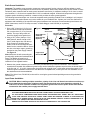
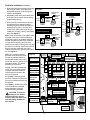
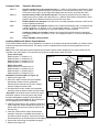
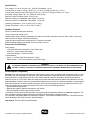
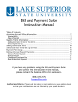
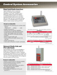
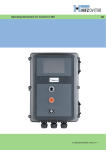
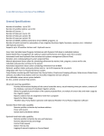
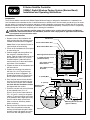
E-Series Satellite Controller
OSMAC Digital Wireless Paging System (Narrow Band)
Installation and Operating Instructions
Introduction
The E-Series satellite controller with OSMAC Digital Wireless Paging is designed for installation on a substantial concrete foundation with imbedded conduit of various diameters to enable power, field and earth ground wiring to be routed
into the cabinet. A mounting bolt positioner and basic mounting hardware components are included with each controller.
Additional materials required to complete the installation must be obtained separately. A material list can be compiled by
reading through the instructions completely prior to starting the installation.
CAUTION: For your protection and the safety of the product user, comply with all Caution and Warning
statements within this document. All installation practices must comply with all applicable national and/or
local electrical and construction codes.
Foundation Construction
1. Prepare a hole for the foundation and
wiring conduit using the minimum recommended dimensions shown in Figure 1.
*Note: Refer to local electrical codes for
required depth of buried wiring.
2. Trench to the foundation site as required
for each wiring run.
3. Position straight and sweep elbow conduit sections in foundation hole as
shown. Tape the conduit ends to seal out
dirt. Backfill soil to form a 6" (15.2cm)
foundation depth. Conduit should not
extend more than 2" above the finished
top surface of the foundation.
4. Prepare the sides of the foundation hole
with wood forms.
5. Prepare the mounting bolt positioner
with the 5/16 x 4-1/2" bolts and nuts
(provided) as shown in Figure 1. The
threads should extend 2" (51mm) from
the top surface of the bolt positioner.
6. Pour concrete into the formed foundation hole. Press the mounting bolt positioner into the concrete until it is flush
and level with the foundation surface
and aligned with the conduit.
7. Finish the concrete with a level flat area
for the pedestal base (13" x 13"
[33cm x 33cm] for the metal cabinet or
16" x 16" [41cm x 41cm] for the plastic
cabinet). To prevent pooling at the base
of the pedestal, add a slight taper away
from the cabinet base contact area.
Allow concrete to sufficiently harden
before continuing.
8. Remove the hex nuts from the mounting
bolts. Place the pedestal on the pad
ensuring all bolts pass though the holes
provided. Install a flat washer and a hex
nut on each bolt and tighten securely.
Figure 1
Wood Form
Plastic Cabinet Base Area
Metal Cabinet Base Area
Mounting Bolt Positioner
3" (76mm) Conduit – Field
(32 Stations Each)
30"
(76cm)
3/4" (19mm) Conduit –
Earth Ground
3/4" (19mm) Conduit–
AC Power
2" (51mm) Max.
FRONT
30"
(76cm)
Taper
6" (15.2cm)
Mounting Bolt
Positioner
See *Note
2"
(51mm)
Mounting Bolt w/ Hex Nuts
(Typical 4 Places)
Concrete
Earth Ground Installation
Important! The satellite surge protection components cannot properly function unless an efficient pathway to earth
ground is provided. The ground path must be as direct as possible, without sharp bends and must not exceed 30 ohms
resistance (when measured with an earth ground resistance test device). A resistance reading of 0–10 ohms is considered excellent, 11–20 ohms is acceptable and 21–30 is considered marginal. All electrical components throughout the
irrigation system should be grounded in a manner which provides the same ground potential.
The following instructions depict one of several acceptable earth grounding methods. Due to variables in soil composition and terrain, the method shown may not be suitable for your installation site. Contact your local Toro distributor for
assistance and availability of the required earth ground resistance test instrument. Recommended ground testers are:
AEMC Instruments, model 3710 clamp-on tester, or Biddle Megger, model 250260 (or equivalent).
Procedure
1. Drive a 5/8" (16mm) by 8' (2.5m) copper-clad steel rod into well-moistened
soil not more than 12' (3.7m) from the
satellite. The top of the ground rod
should be slightly below grade level.
2. Using a 5/8" (16mm) clamp or “Cad
weld” fastener, attach a length of #6
(6mm2) solid copper wire near the top
of the ground rod. Avoiding sharp
bends, route the wire through the foundation into the controller cabinet. Secure
the wire to the large copper ground lug
provided on the power supply chassis.
See Figure 2.
Note: Make sure the soil surrounding the
ground rod(s) remains well moistened at all
times. The addition of some form of
irrigation may be required if the satellite is
installed in a non-irrigated location.
Figure 2
850-00
Valve Cover
Ground Wire To
Additional
Ground Rod(s)
(Optional)
Chassis
Ground Lug
#6 (6mm2) Solid
Copper Ground Wire
WARNING
HIGH
VOLTAGE
115V
Copper-Clad
Ground Rod
12' (3.7m) Maximum
3. Measure the ground resistance per the instructions provided with the ground test instrument. If the resistance
exceeds the acceptable limit, additional ground rod(s) can be installed at a distance equal to twice the buried depth
of the first rod; i.e., 16' (4.9m). Interconnect the ground rods using #6 (6mm2) solid copper wire and test again. If the
measured ground resistance continues to read above the acceptable limit, contact your local Toro distributor for further assistance and recommendations.
Note: A Toro Valve Cover, P/N 850-00, works well for covering the ground rod and providing access to the ground wire
connection(s).
Input Power Installation
CAUTION: When installing multiple controllers, polarity of the Line and Neutral connections must be properly maintained throughout the irrigation system. Reversed polarity may cause damaging potentials to
exist at one or more controller locations. An equipment ground wire from the power source must also be
connected to the satellite power supply terminal block.
WARNING
AC POWER WIRING MUST BE INSTALLED AND CONNECTED BY QUALIFIED PERSONNEL ONLY.
ALL ELECTRICAL COMPONENTS AND INSTALLATION PROCEDURES MUST COMPLY WITH ALL APPLICABLE
LOCAL AND NATIONAL ELECTRICAL CODES. SOME CODES MAY REQUIRE A MEANS OF DISCONNECTION
FROM THE AC POWER SOURCE, INSTALLED IN THE FIXED WIRING, HAVING A CONTACT SEPARATION OF AT
LEAST 0.120" (3MM) IN THE LINE AND NEUTRAL POLES.
ENSURE THE AC POWER SOURCE IS OFF PRIOR TO CONNECTING TO THE CONTROLLER.
2
Input Power Installation (continued)
Procedure
1. Place the controller’s main power switch
in the Off position. See Figure 3.
2. Position the input voltage select switch to
the 115V (for 115-120V service) or 230V
(for 230-240V service) as required.
3. Remove the power wiring access cover
located on the back of the power supply
assembly. See Figure 4.
Note: The power and equipment ground
wires are connected to a terminal block
located on the back of the power supply
assembly. The power wire access hole provided will accommodate a 3/4" (19mm) conduit fitting. If conduit is required by code,
install a section of flexible 3/4" (19mm) electrical conduit from the foundation conduit to
this access hole.
4. Route the appropriate size 3-conductor
cable (10 AWG [2.5mm2] maximum) from
the power source location to the power
supply terminal block.
5. Reference Table 1 for the appropriate
type of power connection. Secure the
wires to the terminal block as indicated in
Figure 4.
6. Reinstall the power wiring access cover.
7. Apply power to the controller.
Figure 3
WARNING
HIGH
VOLTAGE
3.2A Fuse –
Station Output
On
Off
Main Power Switch/
1.5A Circuit Breaker
115V
4.0A Circuit Breaker –
Control Functions
Input Voltage
Select Switch
Table 1
Line
AC Service Type
115/120 V a.c. 50/60 Hz (Dom.)
Equip. Grnd.
Hot (Black)
230/240 V a.c. 50/60 Hz (3-Phase) Hot (Black)
230/240 V a.c. 50/60 Hz (Int)
Neutral
Green
Neutral (White)
Green/Yellow
Hot (Blue or Red)
Hot (Brown) Green/Yellow
Neutral (Blue)
Equipment Ground
Figure 4
Neutral
Line
Note: The satellite incorporates a 24 V a.c.
Hot Post feature on each station output
module which enables control valves to be
identified through momentary activation. To
utilize the Hot Post feature, the satellite
power supply must be switched on.
If you do not wish to use the Hot Post feature,
leave the controller’s main power switch Off
until the installation has been completed. See
page 4, Figure 6.
Cover (Side View)
3/4" (19mm) Conduit
(Optional)
Field Wire Installation
CAUTION: The E-Series OSMAC satellite is capable of operating up to 12 stations simultaneously when
operating with pump, or 16 stations simultaneously without a pump. To prevent possible controller
damage, total output current load must not exceed 3.2 amps. If more than one valve per station will be
connected, calculate the total in-rush current load which would be imposed in the maximum operating
conditions and use this value as a guide during installation and operation of the controller.
Procedure
1. Attach the control and common wires to each valve and/or valve-in-head solenoid leads using an approved waterproof splicing method. Route the wires into the controller cabinet through the 3" (76mm) conduit.
2. If automatic pump start is required, refer to the applicable wiring diagram in Figure 5 (page 4) and install accordingly.
Caution: Do not connect the pump starter directly to the controller’s pump start circuit – damage to
the controller will result.
Note: The pump circuit can also be utilized to control a master valve if required.
3
Field Wire Installation (continued)
3. Secure the field common wire(s) and pump
start relay (or master valve) wire to the
appropriate terminals on the Pump/Com
module. See Figure 6.
4. Momentarily touch each valve control wire
to the Hot Post to activate and identify the
corresponding valve(s).
Figure 5
Pump Power
Source
Single Controller
Pump
Com
Starter
Power
Source
Multiple Controllers
Magnetic
Pump
Starter
To Other
Controllers
Relay
5. Secure the valve control wires to the staPump
24 V a.c.
Pump Power
tion terminals in the preferred order of
1A Max.
Source
Pump
Com
operating sequence. Station terminals are
Mag.
numbered left to right, 1–32 (front) and
Pump
Pump
Starter
33–64 (back). Each terminal can accomPressure Switch With
Starter
2
Controller
Override
Com
Power
modate two 14 gage (1.5mm ) solid copper
Relay Source
wires. See Figure 6.
Pressure Switch
Pump Power
24 V a.c.
Pump
Source
Note: A loop is provided on the plastic chas1A Max.
(Typical)
Magnetic
sis below each output module enabling a
Pump
wiring strain relief to be installed when the
Starter
Pump
Starter
optional standard terminal block connector
Power
Com
is used. After connecting the field wires,
Source
Relay
install a nylon cable tie through the loop and
24 V a.c.
1A Max.
Pump
around the wire bundle. Ensure the terminal
block is properly mated with the output
module connector after tightening the cable
tie. See Figure 6.
Note: The 3-position switches
Figure 6
Field Common
provided on the pump/com mod24 V a.c. Output
LED Indicator
Field Common
ule and the optional station terLED Indicators
Control Switch
minal board enable local control
(one per station)
of the field common, pump circuit
Field Common
and station output. The switch
LED Indicator
positions are as follows:
Pump Circuit
ON (up) – Manually activates the
LED Indicator
circuit. The pump, field common
3A Fuse
or station output will remain on
24 V.a.c. Output
(Station Output)
until the switch is moved to the
LED Indicator
(fuse condition)
AUTO or OFF position.
24 V a.c.
OFF (center) – Manually opens
Output LED
the circuit. Operation of the circuit
Indicator
will not occur while the switch is in
this position.
1A Fuse
24 V a.c.
(Pump Circuit)
AUTO (down) – Enables the circuit
Hot Post
to be automatically controlled
Pump Circuit
Standard
during automatic or manual
Control Switch
Terminal Block
(hand-held radio) operation.
Station Output
CAUTION: To prevent
damage to the station
output circuit fuse, do not
exceed 3 amp load when manually activating multiple station outputs.
Switches (optional)
Pump Output
LED Indicator
Field Common
Terminals (3)
Pump Relay
Terminal
Station Output
Terminals
Cable Tie
Strain Relief
4
(optional)
Selecting the Decoder Radio Frequency
The narrow band decoder module assembly stores four user-selectable
radio frequencies. The frequencies are programmed at the factory or by
the distributor prior to delivery of the satellite. A set of jumper pins, located at the top center of the decoder module, enables the frequency to be
selected by simply placing the jumper on the appropriate pin set. In
most cases, the jumper will be configured properly by the distributor
prior to delivery. However if a frequency change is desired, place the
jumper on the pin set as indicated in Figure 7.
Figure 7
#4
#3
#2
#1
Frequency Number
Jumper Pins
Important: The base station transmitter and decoder must be set to
the same frequency to enable communication.
Assigning the Satellite Address Number
Each satellite requires a 3-digit address number to enable communication with the central controller and/or a hand-held radio. The address
numbers range from 1 (001) through 255 and are issued to the satellite
through an array of eight DIP switches, located on the decoder module
assembly. See Figure 8. In the down position, the switch is Off (open)
and represents a value of 0 (zero). In the up position, the switch is On
(closed) and represents the following address number:
Sw 1 = 1
Sw 2 = 2
Sw 3 = 4
Sw 4 = 8
Sw 5 = 16
Sw 6 = 32
Sw 7 = 64
Sw 8 = 128
To set the satellite address number, place the switch or combination of
switches to the On position which provides the numerical equivalent of
the desired address number.
For example: To set satellite address number 50 (050), start with all
eight DIP switches in the Off (open) position, then close switch numbers 2, 5 and 6; i.e., 2 (Sw 2) + 16 (Sw 5) + 32 (Sw 6) = 50.
Figure 8
DIP Switch Array
O1 2 3 4 5 6 7 8
N
Note: The narrow band satellite utilzes a built-in antenna located on the frequency module assembly. If site conditions
are such that an alternate antenna is required, the optional antenna adapter kit (P/N 102-1204) is required.
Testing Satellite Operation
• Performing a Control Circuit Self Test
A self-test feature is provided to check the functionality of various key
satellite control circuits. Before performing the test, ensure the Field
Common, Pump and Station Output control switches are set to the
AUTO (down) position.
The test is initiated by positioning the TEST/RESET switch, located on the
decoder module, to the TEST position as shown in Figure 9. Testing will
begin immediately and is indicated by the audible clicks of the control
relays and momentary illumination of the LED’s on the various PCB
assemblies. The test will repeat continuously until the TEST/RESET
switch is positioned to the center (normal operation) position.
Note: The RESET position resets the decoder microprocessor to factory
defaults. To take affect, the satellite must be powered up with the
switch in the RESET position. The switch should be placed in the NORMAL position after 15 seconds of operation.
Figure 9
• Performing a Station Output Test
Ensure the Field Common control switch is in the AUTO or ON position and the Pump Circuit control switch is set to the
appropriate position.
One at a time, position each Station Output control switch (if this option is installed) to the ON position and confirm
sprinkler operation.
5
Satellite Operations Using a Hand-Held Radio
The following list of satellite operations can be initiated in the field using a hand-held radio keypad. All operation commands must begin with the following keypad sequence: 9 followed by the 3-digit satellite address number. The command code is then entered, followed by additional digits which represent selected stations and/or run time values. All
station numbers from 1–9 must be entered with a preceding 0; i.e., station 1 is entered as 01.
Example: Confirm communication to the satellite by issuing a manual station start command as follows: Press 9 , the
3-digit satellite address code, command code 7521 and 01 (station 1). The LED indicator on the decoder module should
turn off momentarily. An audible click should be heard from the station relay and the corresponding station output LED
should turn on. Visually check for sprinkler operation. To step forward through the stations, press 1 ; to step back
through the stations, press 2 . To terminate the test, use command code 7520.
*
*
Command Code
7510
7511
7512
7513
7514
7515
7516
7517
7518
7520
7521
7524
7525
7526
7540
7543
7544
7546
8000
8001
8003 00
8003 01
8004
*
*
Operation Description
Turns off individual stations; e.g., 7510 01 02 40 turns off stations 1, 2 and 40.
Turns on individual stations; e.g., 7511 01 02 40 turns on stations 1, 2 and 40.
Syringes individual stations for a predetermined number of 30-second intervals (already defined
in the satellite); e.g., 7512 01 02 turns on stations 1 and 2 for 30-second intervals.
Disables individual stations; e.g., 7513 01 03 disables stations 1 and 3. After this command,
on and off commands will be ignored for stations 1 and 3 until the stations are re-enabled.
(See 7514.)
Enables individual stations; e.g., 7514 01 03 enable stations 1 and 3.
Sequentially syringes a specified station number range; e.g., 7515 10 20 will syringe stations
10 through 20 sequentially.
Sequentially syringes individual stations; e.g., 7516 10 11 will syringe stations 10 and 11.
Multiple syringe groups can also be run. Enter two dashes between stations to designate separate syringe groups; e.g., 7516 10 11 - - 22 24 26 28 will run two sequential syringes at the same
time on stations 10 and 11 and stations 22, 24, 26 and 28.
Turns on individuals stations for a specified number of hours, minutes and seconds; e.g.,
7517 01 30 00 23 24 25 turns stations 23, 24 and 25 on for 1 hour, 30 minutes and no seconds.
Turns on individual stations for a specified number of minutes; e.g., 7518 10 23 24 25 turns
on stations 23, 24 and 25 for 10 minutes.
Turns off a sequential station run operation (initiated by command code 7521).
Turns on a sequential station run operation; e.g., 7521 01 turns on station 1. To step forward
through the stations, press 1 ; to step back through the stations, press 2 .
Turns on individual stations as switches; i.e., does not simultaneously energize the pump.
Note: Will not turn off the pump if already running. E.g., 7524 25 35 45 turns on stations 25, 35
and 45 without energizing the pump.
Turns on individual stations as switches for a time given in minutes; i.e., does not simultaneously energize the pump in this command string, the run time is entered first, followed by the
station numbers; e.g., 7525 25 05 42 turns on stations 5 and 45 for 25 minutes without energizing the pump.
Turns on individual stations as switches for the time given in hours, minutes and seconds. In this command string, the run time is entered first, followed by the station numbers; e.g.,
7526 02 30 45 25 26 27 turns on stations 25, 26 and 27 for 2 hours, 30 minutes and 45 seconds.
Turns off all stations (this satellite only).
Disables all stations in all satellites (rain shutdown). Note: Satellite address code is not used
with 7543 or 7544 command codes. The stations will not respond to any further commands until
enabled.
Enables operation of all stations in all satellites. See Note above.
Sequentially syringes all stations for a set length of time; e.g., 7546 turns on all stations for
the predetermined number of 30 second intervals as defined in the syringe time.
Disables pump start.
Enables pump start to be assigned to a station; e.g., 8001 48 assigns pump start to station 48.
Disables operation and turns off all stations in the satellite with sequential shutdown.
Enables operation of all stations in the satellite.
Changes the password; e.g., 8004 7531 6108 will change the factory default password (7531)
to 6108.
*
*
6
Command Code
8006 01
8006 02
8006 03
8008
8009
8011
Operation Description
Sets the syringe time in 30-second intervals; e.g., 8006 01 0100 (without a password) or 8006
pppp 01 0100 (with a password) sets the syringe time to 100 intervals (50 minutes). The number
of intervals must be given as four digits with leading zeros but can be no greater than 0255.
Sets the time-out limit in 30-minute intervals. This must be specified using four digits with
leading zeros and no greater value than 0255; e.g., 8006 02 0060 (without a password) or 8006
pppp 02 0060 (with a password) sets the time-out limit to 30 hours.
Enables/disables the password. Use 8007 03 01 to enable password protection or 8007 03 00
to cancel password protection.
Configures stations as switches. Stations can be specified individually and in combination with
a range of stations; e.g., 8008 01 12 50 – 60 configures stations 1, 12 and 50 through 60 as
switches. Note: Only a single dash is used when entering a range of stations.
Configures stations for irrigation. Stations can be specified individually and in combination
with a range of stations; e.g., 8009 01 20 45 – 48 configures stations 1, 20 and 45 through 48 for
irrigation.
Resets EPROM to factory defaults.
Installing Additional 8-Station Output Modules
The E-Series OSMAC satellite can be upgraded to a maximum of 64 station outputs with the addition of 8-station output
modules and optional terminal boards. The station module is supplied with the required mounting hardware and connector cable.
Note: Each of the eight output module positions has a specific station number assignment. An output module can be
installed in any open position. The controller recognizes the module station order as follows:
(Front, left to right)
Module position 1 = Stations 1–8
Figure 10
Output Distribution
Module position 2 = Stations 9–16
Board
Module position 3 = Stations 17–24
Backplate
Latch
Module position 4 = Stations 25–32
(Back, left to right)
Module position 1 = Stations 33–40
Module position 2 = Stations 41–48
Ribbon Cable
Module position 3 = Stations 49–56
Module position 4 = Stations 57–64
Installation Procedure (Refer to Figure 10)
8-Station
1. Switch power supply Off.
Output Module
2. Place the 8-station module onto the backplate,
positioning it between the four guideposts.
Machine
Carefully press inward at the top of the module
Screw*
board to engage the plastic latch.
3. Ground and secure the module to the backplate
assembly using the single machine screw provided.
Self-Tapping
*Important: The machine screws connect the output
Screws
and station modules to the 24V power and ground
bus bars and must be installed in the designated
locations as indicated in Figure 10. Do not attempt to
use self-tapping screws in these locations.
4. Install the ribbon cable to the 8-station module and
Machine
Standard-Station
output distribution board receptacles as shown.The
Screws*
Output Terminal
ribbon cable connectors are keyed to insert lin one
Block
direction only.
Self-Tapping
Optional Station Output
5. Insert the optional station output terminal board
Screw
Terminal Board Assembly
assembly connector or standard terminal block to
the station module receptacle. Secure the terminal
board assembly to the chassis with three self-tapping screws and two machine screws provided.
6. Connect the valve wiring as described on page 4.
7. Switch power supply On.
7
Specifications
Line Voltage: 115-120 or 230-240 V a.c. 50/60 Hz (switchable), 130 VA
Current Draw (no load): 0.21A @ 115-120 V a.c., 60 Hz or 0.10A @ 230-240 V a.c., 50 Hz
Current Draw (maximum load): 0.91A @ 115-120 V a.c., 60 Hz or 0.45A @ 230-240 V a.c., 50 Hz
Secondary Voltage Output: 24 V a.c., 50/60 Hz, 3.0A (85 VA)
Maximum Load Per Station Output: 0.75A (18 VA)
Maximum Load Per Pump/Master Valve Output: 1A (24 VA)
Maximum Load Per Pump/Master Valve Output: 1A (24 VA)
Operating Temperature: -10°C to +60°C (14°F to 140°F)
Storage Temperature: -30°C to +65°C (-22°F to 149°F)
Hardware Features
Plastic or painted stainless-steel cabinetry
Front, back and top locking covers
Modular station output capacity upgradeable in 8-station increments. (48-station maximum when used in conjunction
with TouchNet; 64-station maximum with SitePro.)
Optional output terminal board configurations in 16-station increments
Optional antenna adapter kit available. Order kit number 102-xxxx.
Fuses and Circuit Breakers
Power Supply:
1.5A On/Off Switch/Circuit Breaker – Main Power Input
3.2A Fuse – Power Supply (Slow Blow)
4.0A Circuit Breaker – Control Functions
Control Modules:
Pump – 1.0A Fuse (Fast Blow, Automotive Type)
Station Output – 3.0A Fuse (Fast Blow, Automotive Type)
WARNING
IF FUSE REPLACEMENT IS REQUIRED, REPLACE WITH A FUSE OF THE SAME TYPE AND AMPERAGE RATING.
FAILURE TO COMPLY CAN RESULT IN SERIOUS INJURY AND/OR EQUIPMENT DAMAGE DUE TO FIRE HAZARD.
Electromagnetic Compatibility
Domestic: This equipment generates and uses radio frequency energy and if not installed and used properly, that is, in strict
accordance with the manufacturer's instructions, may cause interference to radio and television reception. It has been type
tested and found to comply with the limits for a FCC Class B computing device in accordance with the specifications in
Subpart J of Part 15 of FCC Rules, which are designed to provide reasonable protection against such interference in a residential installation. However, there is no guarantee that interference will not occur in a particular installation. If this equipment
does cause interference to radio or television reception, which can be determined by turning the equipment off and on, the
user is encouraged to try to correct the interference by one or more of the following measures:
• Reorient the receiving antenna.
• Relocate the irrigation controller with respect to the receiver.
• Move the irrigation controller away from the receiver.
If necessary, the user should consult the dealer or an experienced radio/television technician for additional suggestions. The
user may find the following booklet prepared by the Federal Communications Commission helpful:
"How to Identify and Resolve Radio-TV Interference Problems." This booklet is available from the U.S. Government Printing
Office, Washington, DC 20402. Stock No. 004-000-00345-4.
International: This is a CSPR 22 Class B product.
© 2000 The Toro Company, Irrigation Division
Form Number 373-0122 Rev B