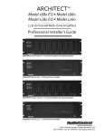
1
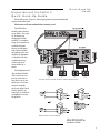
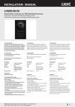
®
The Architect
Model 500 & Model 700
TM
Multi-Zone Power Amplifier / Speaker Optimizer
Professional Installer’s
Consciousness Guide
®
making good stereo sound better®
22410 70th Avenue West
Mountlake Terrace, WA 98043
Phone 425-775-8461 • Fax 425-778-3166
Internet http://www.audiocontrol.com
©1998. All rights reserved.
Important Information
Dealer Name _______________________________________
Date Installed ______________________________________
Serial Number _____________________________________
®
Contents
The Architect® Product Highlights . . . . . . . . . . . . . . . . . . . . . . . 1
Experienced Installer’s Quick Hook-Up Guide . . . . . . . . . . . . . 3
A Guided Tour Of The Architect . . . . . . . . . . . . . . . . . . . . . . . . 4
Hooking Up Your System . . . . . . . . . . . . . . . . . . . . . . . . . . . . . . 6
Installation: The Long Version . . . . . . . . . . . . . . . . . . . . . . . . . . 7
Placement . . . . . . . . . . . . . . . . . . . . . . . . . . . . . . . . . . . . . . . . 7
AC Power . . . . . . . . . . . . . . . . . . . . . . . . . . . . . . . . . . . . . . . 8
Remote Power Control . . . . . . . . . . . . . . . . . . . . . . . . . . . . . 8
Audio Hook-Up . . . . . . . . . . . . . . . . . . . . . . . . . . . . . . . . . . . 9
Speaker Wire Hook-Up . . . . . . . . . . . . . . . . . . . . . . . . . . . . 10
Doing The Deed . . . . . . . . . . . . . . . . . . . . . . . . . . . . . . . . . . . . 10
A Short Introduction To Equalizers And Acoustics . . . . . . 11
Audio Analysis Using Pink Noise . . . . . . . . . . . . . . . . . . . . 12
Information For Control Freaks . . . . . . . . . . . . . . . . . . . . . . . . 13
The Truth About Bass And
The Programmable Frequency Match Filter . . . . . . . . . . . . 14
Changing The PFM Modules . . . . . . . . . . . . . . . . . . . . . . . . . . 15
Troubleshooting . . . . . . . . . . . . . . . . . . . . . . . . . . . . . . . . . . . . 17
A Brazen Plug For Other AudioControl Products . . . . . . . . . . 18
Appendix A - Bridging The Architect . . . . . . . . . . . . . . . . . . . . 19
Appendix B - Building Your Own PFM Modules . . . . . . . . . . . 20
The Warranty . . . . . . . . . . . . . . . . . . . . . . . . . . . . . . . . . . . . . . 22
Legalese Section . . . . . . . . . . . . . . . . . . . . . . . . . . . . . . . . . . . . 23
Service Information . . . . . . . . . . . . . . . . . . . . . . . . . . . . . . . . . . 24
Block Diagram . . . . . . . . . . . . . . . . . . . . . . . . . . . . . . . . . . . . . 25
Specifications . . . . . . . . . . . . . . . . . . . . . . . . . . . . . . . . . . . . . . 25
The Architect
Model 500 & Model 700
Installer’s Guide
®
Product
Highlights
CONGRATULATIONS!
You are now installing a component which can dramatically
improve the performance of any multi-zone audio system, especially those utilizing in-wall speakers. The Architect Model 500 &
700 are American-designed, American-built “set and forget”
component which will provide a lifetime of trouble-free service.
The Architect Model 500 & 700 are made by the only electronics company in the world that specializes in equalizers, signal
processors and audio analyzers. And the company whose professional sound division sells the most popular one-third octave real
time analyzer in the world, the SA-3050. AudioControl’s passion
for high quality, meticulous attention to detail and pro sound
heritage shows itself in the dozens of awards we have won for our
designs, products and service. Now, as when we began, our
greatest satisfaction is our reputation for sonic excellence and
reliability among people just like you throughout the world.
This manual is designed to help you get everything you can
out of your new amplifier/equalizer. So, even though you’re dying
to see it in action, please take a few minutes to slog through our
not-so-weighty prose and learn how to get the most from your
new Architect. Anything with this many knobs deserves all the
explanation it can get.
The Architect® Product Highlights
600 Watts Strong — With twelve powerful channels of
amplification, The Architect will drive 50 watts per channel with
all channels driven. This is a true 600 watt amp design, so go
ahead and put a small quarry of rock speakers by the patio. Then
sit back and enjoy the sound.
Built For The Long Haul — The Architect has been designed
with durability in mind. The Lightdrive protection circuitry defends The Architect and your speakers against clipping, distortion,
damage, parties and even teenagers. Even if the party lasts all
weekend.
Light Drive Protection — Few things are more irritating than
a problem in one zone of an audio system effecting the entire
system. This will not happen with The Architect. Every stereo
output zone features independent protection against short circuits,
over-heating, DC offset and clipping. Even if the protection needs
to kick in, that doesn’t neccessarily mean that the affected zone
will shutdown. If a zone overheats, the smart protection reduces
the power to that zone, allowing it to cool down with only a
The Architect
Model 500 & Model 700
Installer’s Guide
1
Product
Highlights
minimal reduction in speaker volume. Of course the protection
circuits are smart enough to reset themselves when the problem is
solved.
Specially Designed Frequency Controls — (Model 700
only) The Architect Model 700 is intended to provide a dramatic
sound improvement for “small” speakers, such as those with 6inch and 8-inch woofers. The Architect’s 45Hz, 150Hz, 300Hz,
700Hz, 2500Hz and 12kHz band centers were chosen to optimize
in-wall and 2-way bookshelf speakers at critical frequencies where
adjustment is most advantageous. The bandwidths (or ‘Q’ as our
engineering types call it) have also been optimized for the difficulties that in-wall speakers present. This allows The Architect
Model 700 to improve the sound of these smaller speakers better
than any other equalizer.
PFM Programmable Subsonic Filter — The Architect’s
Programmable Frequency Match (PFM) circuitry is an installer
adjustable bass-blocking filter which protects small speakers and
improves their overall sound. The smaller woofers found in most
in-wall or bookshelf speakers cannot reproduce the bass of a
larger speaker (the laws of physics intervene). If called upon to
reproduce a bass note that would cause the speaker to move
PAST its maximum cone travel, damage can result - and even if it
doesn’t, severe audible distortion DOES. The solution is
AudioControl’s exclusive PFM circuit. It gives small woofers only
those frequencies they can use by “chopping off” bass below an
installer programmed frequency (40Hz is the factory setting). The
woofer is protected and can do a better job of reproducing midbass and higher frequencies.
Input Bussing – Sometimes you just want to feed the same
music to every room in the house. You could use a single, stereo
amp and series/parallel the speakers. The problem is that if you get
a short in the system or the amp dies, all of the zones go dead.
The Architect solves that dilemma by letting you send a single
stereo signal to all 12 channels of the Architect with the press of a
button. Every room enjoys independent protection and equalization.
*
Made in the Northwest Rainforest — The Architect began
its existence at our factory in Mountlake Terrace, Washington, a
few miles north of Seattle. Here, we also build precision test
instruments, equalizers and analyzers and a totally awesome line
of car stereo components. AudioControl began in 1977 and has
won so many audio industry awards for design and engineering
excellence that our reception room wall is starting to sag. But
enough about us. Let’s start getting the most from your audio system!
®
2
Quick Hook-Up
Guide
Experienced Installer’s
Quick Hook-Up Guide
What follows are “Express” hook-up diagrams for professionals and
experienced audio buffs.
Make sure to fill out and mail the warranty card.
The PFM filter
module comes factory
set at 40Hz. See page
16 for details on
changing the PFM
modules. A complete
range of frequencies is
available from the
factory and information is also available
on building your own
modules in Appendix
A. Modules are also
available from any
AudioConrol car
stereo dealer in a
pinch.
Final adjustment of
The Architect Model
700’s boost/cut controls in each zone is
best done with a onethird octave real time
analyzer and pink
noise test signal, but it
can be done by ear,
especially if you desire
to emphasize certain
frequencies.
Six Zone System with The Architect and Preamp/Controller
Remote Power Control Hookup
The Architect
Model 500 & Model 700
Installer’s Guide
3
A Guided Tour Of
The ArchitectTM Model 500 & Model 700
1
2
Front panel:
1. Stereo Speaker Optimizer Controls —
(Model 700 only) This sea of knobs provide up to
12dB boost or cut at 45Hz, 150Hz, 300Hz,
700Hz, 2500Hz and 12KHz. After initial adjustment the only time you would change the control
settings are 1) if you connect different speakers
into the system, 2) if (assuming the speakers
aren’t built-in) you move them significantly, such
as from a bookshelf to floor stands, or 3) if your
room acoustics change through addition or
rearrangement of furniture, wall or floor coverings, large hairy dogs, etc.
Note: If you have the Signal-Sense
turned on, then the status LED will
not turn on until there is an audio
signal present on that zone’s inputs.
®
4
3
4
2. Channel Status LEDs — These dualcolor LEDs serve two purposes. First, they
illuminate Green when the corresponding zone is
active. The second function of the status LED is
to turn Amber if something has caused that zone
to go into protection.
3. Protection LED — This LED also has
two faces. In normal operation it glows Green
when the remote power trigger is active and The
Architect is in stand-by. If the Protection LED
turns Amber, then one of the internal protection
circuits have come into use. All the protection
circuits automatically reset themselves when the
problem causing the fault has been fixed.
4. Power LED — Nothing too tricky
here...if you have the Master Power switch (on
the back panel) turned on and The Architect is
plugged into an active AC outlet, this little red
light will shine forth.
A Guided Tour Of
The Architect™ Model 500 & Model 700
2
3
4
8
9
1
6
5
7
Back panel:
1. Inputs — These unbalanced RCA inputs
connect to your control preamplifier’s outputs. The
signal sense and equalizer circuitry work in channel
pairs (1&2, 3&4, etc.) but you can still use each
input as a separate mono channel.
2. Input Bus Switches — Sometimes you need
to feed the same audio signal to multiple channels of
the Architect. The Input Bus switch lets you gang
three zones together with the press of a button.
3. Input Level Controls — These stereoganged controls vary the input sensitiviy of the
Architect.
4. Speaker Outputs — These terminal blocks
are designed to make an installer smile. You can
unplug the blocks and connect all of the speaker
wires to them without balancing The Architect on
your lap. This also makes it very simple to pre-wire
a system without ever taking The Architect out to the
installation site. The speaker connector blocks will
accept up to 12 awg wire.
5. Signal Sense Defeat — The signal sensing
circuitry activates a zone approximately one second
after an audio signal is present on the Input RCA
jacks. To defeat this function and leave The Architect ready to play at all times, press this switch in to
the recessed (Defeat) position.
6. Remote Power Control — This three pin
connector allows you to remotely turn on The
Architect. You can either use a contact closure
10
between the Control In and the +12VDC output or an
external 12 volt trigger between the Control In and
Ground terminals. The +12 volt output is not designed
to power other pieces of equipment. It is a current
limited output for switching The Architect only.
7. Ground Lift Switch – This switch selects
the level of isolation between the audio signal
ground and your AC earth ground. In normal
operation this switch should be in the Ground
position, but if you run into trouble with an AC
ground hum, try the other two settings for the
best operation. For your safety, the chassis is
always connected to ground regardless of the
switch setting.
8. Master Power Switch — This switch shuts
off the main AC power. Normally the only time you
need to turn off the master power is if the homeowner is going to be gone on vacation for the
summer.
9. AC Power Fuse — The Architect is
designed with several layers of protection circuitry.
This power fuse is here just in case something really
awful goes wrong.
10. Power Cord — The Architect draws a
hefty 1000 watts. Make certain that it is plugged
directly into the wall outlet or a power strip with
sufficient power rating. Since The Architect has
remote power switching, you can plug the unit into
an outlet that is always active.
The Architect
Model 500 & Model 700
Installer’s Guide
5
Hooking Up
Your System
Hooking Up Your System
What you’ll need:
1. The Architect Multi-Zone Power Amp.
2. RCA audio hook-up cables.
3. (Optional) A balanced line driver if you are going to
mount The Architect more than 20 feet from the control
preamp.
4. (Also Optional) Rack Mounting Kit to install the
Architect into a standard 19” rack.
5. Enough speaker wire to reach all of your speakers.
6. Multi-zone controller, receiver, or preamplifier.
7. Although you can set the speaker optimization controls
by ear, a real-time audio analyzer such as the
AudioControl SA-3052 is very helpful.
®
6
Installation:
The Long Version
Installation:
The Long
Version
What follows is a step-by-step guide to integrating The Architect into your multi-zone system. If it seems overly detailed, please
forgive us. We would rather tell you too much than too little.
First, check your new Architect for any shipping damage. We
pack ‘em pretty securely, but it’s a vicious world out there and
anything can happen twixt Mountlake Terrace, Washington, and
your installation.
Paperwork
Yes, filling out the warranty registration card is about as exciting as cleaning out your sock drawer, but we’d definitely like the
card back after you’ve hooked up The Architect and played with it
a while. We DO read each and every incoming card and react to
your suggestions. That’s how great products like this are created.
Next, record the serial number on the sales receipt and make
certain the home owner puts it away in a safe place. Stashing the
receipt away is very important in the unlikely event that your
Architect ever needs servicing, or…well things do happen…you
sometimes need to prove to an insurance adjuster that something as
great as The Architect was installed in the system.
Placement
The Architect is a very efficient amplifier, but it does need
some breathing room to operate properly. Make certain that the
vents on the top and bottom are not blocked and have at least ½”
of air space. Also make certain that heat sensitive components such
as CD or tape players are not directly on top of The Architect. Just
as a reminder, you should avoid putting any leaky potted plants in
your stereo stack.
A benefit of having a remote power control on The Architect is
that you can install it in another area of the house (such as a basement or utility room) away from the main component stack. Make
certain that you use a good quality audio line driver (the
AudioConrol BLD-10 and BLR-10 come to mind) to extend the
RCA cables if you choose this remote type of installation.
The Architect
Model 500 & Model 700
Installer’s Guide
7
Installation:
The Long
Version
AC Power
Under normal operating conditions, The Architect can draw
up to 1000 watts of AC power. Don’t plug it into a switched
outlet on your system unless you are certain that it can handle the
power rating. Also, please don’t cut off the ground pin on the
power connector. It is an important safety feature. If you need to
plug it into a two prong outlet, use a ground adapter (and connect
the ground on it).
Remote Power Control
The Architect has three levels of power control.
1. Main AC Power Switch — This is the master control and
must be turned ON for The Architect to function. When the main
power switch is on, the red Power LED on the front panel lights
up. Normally the only time that you would need to turn the AC
power switch off is when the system is going to be unused for an
extended period.
Installation Hint: If your
installation doesn’t require
this remote power turn-on, you
must put a short piece of wire
between the +12 V output and the
Control Input pins.
2. Remote Power Control — This removable 3-pin remote
connector on the rear panel allows simple interfacing with external
control systems. It accepts either a contact closure or external +12
volts DC (see diagram). The two-color Protection LED on the
front panel illuminates Green to show that the remote power
control is active and The Architect® is in Stand-by.
Note: The channels are paired into
stereo zones (channels 1&2, 3&4,
etc.). The signal-sense control
effects both channels in a zone at
the same time even if only one input
is used.
3. Signal-Sense Circuit — This provides individual zone
power control. When active, it senses that an audio signal is
present on the RCA inputs, enables the power and unmutes that
zone. The zone status LEDs on the front panel light up Green
when a signal is present.
In some installations it may be desirable to defeat the signalsense control and leave all zones active regardless of the audio
input. To defeat the signal-sense, press in the Signal-Sense Defeat
button on the rear panel.
Note: If you are not using the
Remote Power Control you must
connect the +12 V output to the
control input.
®
8
Audio hook-up
Installation:
The Long
Version
If you’re an installation veteran, this may seem repetitive, but
some things can never be repeated too many times (just ask our
Customer Support Department).
1. Turn off ALL components before making any connections.
2. When making connections, designate RED RCA plugs as
RIGHT and WHITE, BLACK, or GREY plugs as LEFT. In fact,
this is a good idea for ALL signal connections made in your audio
system. The key is consistency. Stick with the same color-coding
and you’ll reduce possible problems.
3. If the same audio signal needs to feed multiple channels the
Input Bus switch on the Architect must be pressed ‘in’.
4. Whenever possible, keep power cords away from signal
cables to prevent induced hum. This is especially important if you
bundle the cables to keep the installation neat looking.
5. Use quality interconnect cables. We’re not going to get into
the debate about whether $100/meter cables improve the sound,
but we know from experience that really, REALLY cheap cables
can cause a multitude of problems. They tend to break inside or
corrode, causing a loss of signal or hum. They also can have poor
shielding.
Twelve Channel Multi-Room System
using the BLD-10/BLR-10 line
driver
Bus switch out
6. If you need to run the RCA audio cables more than 20 feet
you should consider using a balanced line driver for the signals.
This will provide better noise rejection against nasty things like
hum, spikes, local
talk radio, etc. Ask
your AudioControl
representative for
more information
about line drivers.
The Architect
Model 500 & Model 700
Installer’s Guide
9
Doing the Deed
Speaker wire hook-up
The same rule applies to the speaker wires as the RCA connections. Establish a standard connection guideline and stick with
it. One conductor of the speaker wire is normally marked by a
different color (silver versus copper) or there is a ribbing on one
side. Typically this marked conductor is used for the positive (+)
speaker leads. Of course the really good wire has Positive and
Negative printed right on the wire jacket.
Take care when running the speaker wires not to cut the
insulation pulling around metal ducts or frames. Also, watch out
for errant staples punching into the wire.
If you do have a short in a speaker wire the protection circuits
in The Architect will show an amber status LED for the shorted
zone. The status LED will cycle on/off only when the volume is
turned up in the shorted zone.
See Appendix B for information about bridging The Architect
into mono operation.
Installation Hint: For the
absolutely best results, The
Architect™ Model 700 should be
adjusted with a real time analyzer
such as the AudioControl Industrial
SA-3052.
Doing The Deed
Before proceeding on to setting up the Speaker Optimization
controls on The Architect, it’s a good idea to make sure that you
have everything connected and working properly.
1.
Double-check all connections. Make certain that all of the
audio and speaker connections are firmly seated and tightened down.
2.
Turn on your audio system. The Power LED on The Architect should be Red, the Protection LED should be Green and
(unless you have defeated the Signal-Sense), all of the Zone
Status LEDs should be off.
3.
Start one of the audio sources playing and select a zone (how
you do this depends on your multi-room control system). The
zone status LED should light Green approximately one
second after the music begins.
4.
Continuing checking each zone to ensure that every one plays
properly.
5.
Congratulations! You’re ready to go on to setting the
Speaker Optimization controls.
You’re almost done! Now for the details of operation…
®
10
Doing the Deed
A Short Introduction To Equalizers And Acoustics
Magazine reviewers and audio system owners spend much
time critically appraising speaker and other stereo components.
Unfortunately, a phenomenon that has a very large effect upon
sound is not is easily judged or changed. That effect is the
ACOUSTICS of the environment in which you are listening.
Room acoustics is a complicated subject about which entire
textbooks have been written. We simply want you to be aware of a
few basics that have a direct effect on real time audio analysis.
Sound travels in waves, as
you probably learned in junior
high school. In a stereo system,
these waves are created by the
speakers. Like waves in a pond
created by a splash, sound waves
emanate from the transducers
(drivers) in your speakers and
spread out into the room. If your
room were infinitely big, that’s all
there would be to it. But just like
waves in a pond reach the bank
and reflect back, sound waves
bounce off walls, ceilings, and
floors, reflecting, reinforcing and
canceling each other as shown in
the figure above. Since sound is
energy, the way it reflects depends upon the angle of the surface,
the type of material and the frequency of the sound wave. Because
your listening position is likely to be towards the back of the Free
Field waves shown in the diagram, you also get part of the reflected Reverberant Field as well.
Room interaction
Now we add the next set of complications: Different frequencies of sound have different wave lengths (a function of frequency
and the speed of sound). Each frequency’s wavelength contributes differently to the Free and Reverberant Fields because they
are different sizes. For example, a 32Hz bass note has a wavelength of 35 FEET, while a 16,000Hz note has a wavelength just
under a tenth of an inch. Tiny treble waves can be caught and
neutralized by draperies, carpeting, upholstered furniture and
gangs of indolent Persian cats…while gigantic bass waves simply
slosh back and forth in the room.
The Architect
Model 500 & Model 700
Installer’s Guide
11
Doing the Deed
Another set of variables is the shape and volume of your
listening room. Large rooms require more bass energy to excite
waves within them. Small rooms need less energy, but reflect it
differently. And then there’s the fact that most rooms don’t have
four walls anymore, but open into dining rooms, lofts, cathedral
ceilings, etc. All of this means that predicting sound interaction
patterns is very difficult due to the irregularities of the room
shape.
As you can see, room acoustics is an important but complicated subject (To learn more about room acoustics, send for
AudioControl’s Technical Paper 107, “Small Room Acoustics DeMythologized”). The overall point that we’re trying to make is
that the various rooms in your home function as gigantic mechanical equalizers, boosting or cutting certain frequencies depending
on size, shape, volume, acoustic treatment and the position of the
speakers.
Audio Analysis Using Pink Noise
It may take several series of adjustments since there is some
interaction between each control. We have included some sample
settings and general descriptions of each control’s function on
page 13.
After initial adjustment the only time you would change the
control settings are 1) if you connect different speakers into the
system, 2) if (assuming the speakers aren’t built-in) you move
them significantly, such as from a bookshelf to floor stands, or 3)
if your room acoustics change through rearrangement of furniture,
wall or floor coverings, large hairy dogs, etc.
The following are examples of typical settings along with short
descriptions of each Architect Model 700 Speaker Optimizer
control. Naturally, the results of adjustments will vary depending
on the acoustic environment, type of speaker and sound sources
you are using, but this is a good starting point.
For an extensive description on the use for the SA-3052 real
time spectrum analyzer for these settings, please see that product’s
manual.
®
12
Information For Control Freaks
Information
for Control
Freaks
Here is a brief introduction to each of the Speaker Optimization control frequencies and what their effect on your music is.
45Hz — Low bass. This is about the lowest frequency which
in-wall, extension and small bookshelf speakers can achieve.
Boosting it too far might cause problems, even though The
Architect’s PFM filter cuts frequencies under 40Hz. But if your
speakers can take it, a mild boost will enhance bass instruments
such as Fender bass, kick drum, floor toms, timpani and double
bass violas.
150Hz — High bass. There’s a lot of bass information at this
frequency. In fact, most modern music is mixed to enhance this
area of the frequency spectrum. 150Hz also determines the depth
of male vocals and contains reverberant information which contributes to the spaciousness of sound. Boosting 150Hz can add
“POW!” and impact to bass or it can make the sound “bonky” and
“boomy”. This is a critical adjustment with small or in-wall speakers. Experiment with it.
Example Settings
300Hz and 700Hz — High and low midrange. These controls
directly effect the sound of instruments and vocals. These bands
also determine the speaker’s presence (whether the music sounds
far away or close in). Small speakers often produce too much
midrange, so these controls are candidates for being turned down
slightly during your initial experimentation. Definitely consider
reducing 700Hz if you are only using your extension speakers for
background music.
2500Hz — Treble. Female vocals and the “edge” of instruments such as guitars, snare drums, saxes, violins, etc. are found in
this range. If accentuated too much (by boosting this control)
sounds in the 2500Hz range can seem harsh and fatiguing to the
ear due to excessive output by the speaker or because of live,
reflective room acoustics.
12kHz — High treble. The fine detail, texture and sheen of
music is found here. The breathiness of vocals, the “sheen” of
cymbals, the high overtones of piano and strings. Actually, there’s
audible music information up to 20,000Hz on some CD’s and
most adult’s hearing is still pretty good at 15,000Hz. But we’ve
chosen 12,000Hz because it provides more useful control to
compensate for room acoustics and common small-speaker deficiencies.
The Architect
Model 500 & Model 700
Installer’s Guide
13
The Truth About
Bass & The
Programmable
Frequency
Match Filter
The Truth About Bass And
The Programmable
Frequency Match Filter
Now that digital audio is the favorite musical source, there’s
more low bass running around in a typical system. Low bass
injects large amounts of power into ANY kind of speaker — up to
60% of your amplifier’s output is being used to reproduce frequencies under 100Hz. That can really tax a system which is
driving multiple speakers from a single amplifier channel. The
second problem is that bass produces heat in the speaker. If more
heat is built up than the speaker can dissipate, the driver coil can
literally go into meltdown (or worse).
In addition, ultra-low bass and small speakers don’t always get
along, ESPECIALLY when you DO have ample power. The low
bass music content can cause over-excursion: The speaker cone
attempts to travel farther than its physical limits, potentially
causing damage (in some cases you can actually hear a clacking
sound!). Even before destruction sets in, there are other problems
with feeding super-low bass to small speakers. Most bookshelf
and in-wall loudspeakers are 2-way systems. That means that the
woofer also handles a large part of the critical midrange area.
When the woofer is bashing around trying to reproduce unrealistically low bass, it’s ability to produce midrange is compromised
due to intermodulation distortion. So not only don’t you get low
bass, you get lousy vocal and instrumental reproduction.
Pragmatically, it boils down to this: If you want ultra-low,
foundation-shaking bass from an in-wall speaker, you should add
in a separate subwoofer, a somewhat expensive approach. A more
economic approach is to equalize the speaker for maximum low
bass output WITHIN IT’S PRACTICAL RANGE and eliminate
®
14
lower frequencies which either can’t be reproduced or which incite
excessive cone travel.
The equalization part is handled by The Architect® Model
700’s 45Hz control. The prevention part is handled by The Architect® Programmable Frequency Match filter circuit. While it may
seem surprising, actually cutting off some of the lowest bass will
make the bass sound cleaner, punchier and even louder.
The Truth About
Bass & The
Programmable
Frequency
Match Filter
AudioControl’s Programmable Frequency Match circuit is an
adjustable subsonic filter which cuts off low frequencies. The PFM
filter’s cut-off point is adjustable via a small resistor module inside
The Architect®. When you receive your unit, it is programmed
with a 40Hz bass cut-off. Depending on the application, you may
want to change the filter frequency. Don’t let ego get in the way
and set the PFM too low because somebody thinks that a 6”
woofer should be able to play down to 20Hz.
The following standard module frequencies are available from
AudioControl: 20, 25, 35, 40, 45, 50, 60, 70, 80, 90, 100, 120,
130, 150, 200, and several higher frequencies going up to 6000Hz
which probably aren’t applicable except in very special circumstances. Each module’s frequency is determined by 6 resistors
inside a 14-pin DIP network. See Appendix A for details on
building your own modules.
PFM rolloff curve
Close-up view of PFM Modules
Note: The modules are not
directional so it does not matter
which way they are inserted.
The Architect
Model 500 & Model 700
Installer’s Guide
15
Changing The
PFM Modules
Changing The PFM Modules
WARNING: Unplug the Architect from AC
power before beginning. There are dangerous
voltages present inside.
The first task in changing the PFM modules
is to remove the top chassis of the Architect.
To do this, first remove the 18 screws marked
in the figure above. Now let your wrist relax
for a few moments and survey the innards of
this beast. The PFM modules are located on the
circuit board that runs along the rear of the
Architect (see figure).
Use a small screwdriver to gently pry the
existing modules from their sockets taking care
not to bend the contact pins.
Now you can install the replacement modules. There is
NO POLARITY to these
modules so they can install in
either direction.
Removing the Cover
Now you can put the top
back onto the Architect and go
back to enjoying your music.
Changing the PFM Modules
®
16
Troubleshooting
The Architect
Troubleshooting
The Architect
Almost all problems can be eliminated by re-checking the
wiring and settings of the Architect. If a problem cannot be solved
using the guide below, please call the AudioControl factory for
further assistance.
1. No Sound:
• Verify Power LED in on.
• Verify Protection LED is Green.
• Verify Channel Status LED for zone is Green.
• Verify Source unit is operating.
• Check the Speaker Connector plug on the rear panel.
• Check the AC Power Fuse on the rear panel.
2. Protection LED is Green, but no Channel Status LEDs are on:
• Verify Source unit is operating.
• Try turning up the volume higher.
• Defeat the Signal-Sense using switch on rear panel. All
Channel Status LEDs should turn on. If not, call the
factory.
3. Channel Status LED is Amber:
• Check speaker leads for short.
• If the Architect is excessively hot, turn down the volume
and allow it to cool off. The Status LED should turn back
to Green after a short while.
• The speaker impedance may be too low.
4. Protection LED is Amber:
• Something seriously wrong has happened inside the
Architect. Please contact the factory.
5. Speaker Buzzing or Cracking at high volume:
• Reduce the equalizer boost at 45Hz or 150Hz.
• Try a higher PFM filter frequency. The factory setting is
40Hz.
6. There is no signal, but the Channel Status LED is still Green:
• Check the Signal-Sense defeat switch on the rear panel. If
it is pressed in, the Channel Status LEDs will stay on as
long as the Remote Power Control is enabled.
• The Channel Status LEDs stays on for several minutes
after the audio signal has stopped to prevent prematurely
turning off during quiet passages or disk changes.
The Architect
Model 500 & Model 700
Installer’s Guide
17
A Brazen Plug
For Other
AudioControl
Products
A Brazen Plug For Other
AudioControl Products
AudioControl started out making graphic equalizers in 1977.
In a way, The Architect Model 700 is a powered equalizer and,
like our other models, can make a greater improvement in the
sound of your system than almost any other addition or upgrade.
More bass, better bass, less harshness and the ability to hear music
the way you want it.
We make our equalizers easy to use by incorporating features
such as paired or ganged sliders, as well as subsonic filters and, in
some models, built-in test analyzers
that let you make accurate
adjustments to instantly compensate for main system
speaker and room deficiencies.
In fact, AudioControl was the
world’s first manufacturer of a
SEVEN CHANNEL equalizer
for home theater use.
The Bijou - THX Room Equalizer
AudioControl manufactures a full line of sound processing
products for home theatre and multi-room audio installations. Our
multi-room controller is Stylish, Smart and Simple. It offers the
power to independently control the audio in 6 different rooms and
wall stations with enough styling options to fit any decor from
French Provincial to Nouveau Neon. The balanced line driver and
receivers stretch audio signals up to 1000 feet to extend the reach
BLD-10 4-channel Balanced Line Driver
BLR-10 4-channel Balanced Line Reciever
®
18
of amplifiers, CD Players and other audio components with
inexpensive twisted-pair wiring. For home theatre we offer equalizers to get the best possible sound on everything from Pro-Logic
to Dolby Digital. We also make a killer bass processor, The Phase
Coupled Activator. This component brings out the visceral reality
of your favorite films.
Okay, enough commercials.
Once again, we thank you for adding an AudioControl component to your system and hope you enjoy a lifetime of performance
and convenience.
The Director Model 46 Audio Multi-Room Controller
AudioControl Phase Coupled Activator
The Architect
Model 500 & Model 700
Installer’s Guide
19
Appendix A
Appendix A - Bridging The Architect
Caution - When bridging a zone, the minimum
speaker load impedance on that bridged output is
4 ohms. In a bridged system, each channel of the
bridged pair “sees” one half of the speaker load.
This means that a bridged amp driving a 4 ohm
speaker is operating into a 2 ohm load.
To increase the output power of The Architect, you can join
(bridge) the two channels of one zone into a single channel of 100
watts. Accomplishing this is a simple matter. Just connect the
audio input to both channels of that zone using a ‘Y’ cord adapter
and then connect the speaker terminals as shown in the diagram
below.
Bridge connection showing ‘Y’ cord
and Speaker Hookup
®
20
Appendix B
Appendix B - Building Your Own PFM Modules
Standard Module Frequencies
18dB/octave (14 pin)
Frequency
Frequency
20 Hz
100 Hz
25 Hz
120 Hz
35 Hz
130 Hz
40 Hz
150 Hz
45 Hz
170 Hz
50 Hz
200 Hz
60 Hz
270 Hz
65 Hz
350 Hz
70 Hz
500 Hz
80 Hz
725 Hz
90 Hz
950 Hz
AudioControl PFM filters use resistor modules for frequency
programming. All modules are constructed in the same way, with
the exception of the actual value of the resistors used. In each
module, ALL resistor values are equal. The resistor value for any
given frequency is chosen according to the following equation:
Resistor (kilohms) = 7200 ÷ frequency (Hz)
Example: To find the resistors needed for 1000 Hz.
R (kilohms) = 7200 ÷ 1000
R (kilohms) = 7.2
R = 7.2 K = 7200 ohms
Building Modules
PFM modules require 6 resistors mounted on a 14-pin DIP
header. In the 14-pin modules, the middle resistor position is
unused and may be left unconnected. We recommend 5% ¼ watt
carbon film resistors, or if you really want to be spot-on, 1%
metal-film resistors (difficult to get).
The DIP headers are available from Radio Shack or other
electronic parts distributors. Radio Shack seems to carry more
16-pin headers than 14-pin, so you may have to manufacture a 14pin unit by cutting off the last 2 pins. It will make things easier if
you buy a 16-pin IC socket as well. You can chuck the socket in
your vise and have a handy fixture to hold the header while you
solder.
Do not be confused by the modules from the factory that do
not show individual resistors. They really are there, just encased in
plastic.
Note: Center Resistor is absent
The Architect
Model 500 & Model 700
Installer’s Guide
21
Appendix B
Frequencies by Resistor Value
Five-percent resistors are available in 24 standard values per
decade (this means that from 10 to 100 ohms, there are 24 values). The following table lists the crossover frequencies that
result from using these standard 5% values.
Frequency Value
965 Hz
822 Hz
795 Hz
723 Hz
658 Hz
603 Hz
556 Hz
482 Hz
452 Hz
402 Hz
362 Hz
329 Hz
301 Hz
268 Hz
241 Hz
219 Hz
201 Hz
185 Hz
168 Hz
154 Hz
142 Hz
®
22
7500 Ω
8200 Ω
9100 Ω
10 KΩ
11 KΩ
12 KΩ
13 KΩ
15 KΩ
16 KΩ
18 KΩ
20 KΩ
22 KΩ
24 KΩ
27 KΩ
30 KΩ
33 KΩ
36 KΩ
39 KΩ
43 KΩ
47 KΩ
51 KΩ
Frequency Value
129 Hz
117 Hz
106 Hz
96 Hz
88 Hz
79 Hz
72 Hz
66 Hz
60 Hz
56 Hz
48 Hz
45 Hz
40 Hz
36 Hz
33 Hz
30 Hz
27 Hz
24 Hz
22 Hz
20 Hz
15 Hz
56 KΩ
62 KΩ
68 KΩ
75 KΩ
82 KΩ
91 KΩ
100 KΩ
110 KΩ
120 KΩ
130 KΩ
150 KΩ
160 KΩ
180 KΩ
200 KΩ
220 KΩ
240 KΩ
270 KΩ
300 KΩ
330 KΩ
360 KΩ
470 KΩ
The Warranty
The WARRANTY
People are scared of warranties. Lots of fine print. Months of
waiting around. Well, fear no more. This warranty is designed to
make you rave about us to your friends. It’s a warranty that looks
out for you and helps you resist the temptation to have your
friend, who’s “good with electronics”, try to repair your
AudioControl product. So go ahead, read this warranty, then take
a few days to enjoy your new Architect before sending in the
warranty card and comments.
“Conditional” doesn’t mean anything ominous. The Federal
Trade Commission tells all manufacturers to use the term to
indicate that certain conditions have to be met before they’ll honor
the warranty. If you meet all of these conditions, we will warrant
all materials and workmanship on The Architect for five (5) years
from the date you bought it, and we will fix or replace it, at our
option, during that time.
Here are the conditional conditions:
1. You have to fill out the warranty card and send it to us
within 15 days after installing the The Architect.
2. You must keep your sales receipt for proof of purchase
showing when and from whom the unit was purchased. We’re not
the only ones who require this, so it’s a good habit to get into with
any major purchase.
3. The Architect must have originally been purchased from an
authorized AudioControl dealer. You do not have to be the
original owner, but you do need a copy of the original sales slip.
4. You cannot let anybody who isn’t: (A) the AudioControl
factory; or (B) somebody authorized in writing by AudioControl
to service the The Architect equalizer. If anyone other than (A),
or (B) messes with The Architect, that voids your warranty.
5. The warranty is also void if the serial number is altered or
removed, or if The Architect has been used improperly. Now that
sounds like a big loophole, but here is all we mean by it:
Unwarranted abuse is: (A) physical damage (don’t use The
Architect® to level your projection TV); (B) improper connections
(120 volts into the RCA jacks can fry the poor thing); (C) sadistic
things. This is the best product we know how to build, but if you
strap it to the front bumper of your Range Rover, something might
break.
Assuming you conform to 1 through 5, and it really isn’t all
that hard to do, we get the option of fixing your old unit or replacing it with a new one.
Legalese Section
This is the only warranty given
by AudioControl. This warranty
gives you specific legal rights,
and you may also have rights
that vary from state to state.
Promises of how well The
Architect will work are not
implied by this warranty. Other
than what we’ve said we’ll do in
this warranty, we have no
obligation, express or implied.
We make no warranty of merchantability or fitness for any
particular purpose. Also neither
we nor anyone else who has been
involved in the development or
manufacture of the unit will have
any liability of any incidental,
consequential, special or punitive
damages, including but not
limited to any lost profits or
damage to other parts of your
system by hooking up to the unit
(whether the claim is one for
breach of warranty, negligence of
other tort, or any other kind of
claim). Some states do not allow
limitations of consequential
damages.
Failure to send in a properly
completed warranty card negates
any service claims.
The warranty included with the
unit shall supersede this plaintext version if there is any
inconsistency between the two.
The Architect
Model 500 & Model 700
Installer’s Guide
23
What to do if
you need
service
What to do if you need
service
First, contact AudioControl, either by phone (425)775-8461
or FAX (425)778-3166. We’ll verify if there is anything wrong
that you can fix yourself, or arrange to have it sent back to our
factory for repair. Please include the following items with the
returning unit:
1) A copy of your proof of purchase (that sales receipt we’ve
been harping about). No originals please. We cannot guarantee returning them to you.
2)
A brief explanation of the trouble you are having with The
Architect®. (You’d be surprised how many people forget
this.)
3)
A return street address. (No PO Boxes, please)
4)
A daytime phone number in case our technican has a question
about the problem you are having.
You’re responsible for the freight charges to us, but we’ll pay
the return freight back. We match whatever shipping method you
use to send it to us, so if you return the unit overnight freight, we
send it back overnight. We recommend United Parcel Service
(UPS) for most shipments.
Repair service is available at:
Attn: Service Department
22410 70th Avenue West
Mountlake Terrace, WA 98043 USA
Phone 425/775-8461 • FAX 425/778-3166
e-mail: [email protected]
®
24
BLOCK DIAGRAM
Block
Diagram &
Specifications
SPECIFICATIONS Model 500 & Model 700
Amplifier Power Rating . . . . . . . . . . . . . . . . . . . . . 50 Watts @ 8 ohms
Bridged Power . . . . . . . . . . . . . . . . . . . . . . . . . . . . 100 watts @ 8 ohms
Minimum Recommended Speaker Load . . . . . . . . . . . . . . . . . . . 4 ohms
(2 ohms in limited zones)
Damping Factor . . . . . . . . . . . . . . . . . . . . . . . . . . . . . Greater than 200
EQ Center Frequencies . . . . . . . 45Hz, 150, 300, 700, 2500 and 12kHz
S/N ratio . . . . . . . . . . . . . . . . . . . . . . >100 dB, A-wtd, ref. Full Output
Total Harmonic Distortion . . . . . . . . 0.05% (50 watts/8 ohms 20-20K)
Input Sensitivity . . . . . . . . . . . . . . . . . . . . . . . . . . . . . . . . 0-1V variable
Crosstalk . . . . . . . . . . . . . . . . . >75 dB (1 kHz, Any channel to channel)
Input Impedance . . . . . . . . . . . . . . . . . . . . . . . . . . . . . . . . . 100 Kilohms
Protection . . . . . . . . . . . . Clipping, Thermal, Short Circuit, DC Offset
Power Consumption (all channels driven full power) . . . . . . . 960 watts
Weight . . . . . . . . . . . . . . . . . . . . . . . . . . . . . . . . . . . . . . . . . . . 35 pounds
Dimensions . . . . . . . . . . . . . . . . . . . . . . . . . . . . 17"W x 16"D x 5.25"H
US Patent # . . . . . . . . . . . . . . . . . . . . . . . . . . . . . . . . . . . . . . . 5,708,577
Country of Origin . . . . . . . . . . . . . . . . . . . . . . . . . . . . . . . . . . . . U.S.A.
© AudioControl 1998, All Rights Reserved.
This manual was written, designed, printed and stuffed into the
box in the U.S.A. Probably on a really soggy day considering
where we live.
The Architect
Model 500 & Model 700
Installer’s Guide
25
®
making good stereo sound better®
22410 70th Avenue West
Mountlake Terrace, WA 98043
Phone 425-775-8461 • Fax 425-778-3166
Internet http://www.audiocontrol.com
P/N 9130440