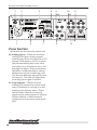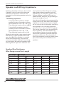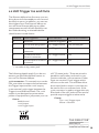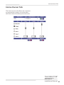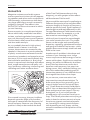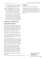
1
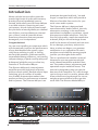
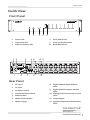
The Director™ Model M6400
16 CHANNEL MULTI-ZONE NETWORK MATRIX AMPLIFIER
Installation Manual
Important Safety Instructions
Important Safety
Instructions
1.
2.
3.
4.
5.
6.
7.
8.
9.
10.
11.
12.
13.
Read these instructions. Keep these instructions.
Heed all warnings.
Follow all instructions.
Do not use this apparatus near water.
Clean only with a dry cloth.
Do not block any ventilation openings. Install in accordance with the manufacturer’s
instructions.
Do not install near any heat sources such
as radiators, heat registers, stoves, or
other apparatus (including amplifiers) that
produce heat.
Protect the power cord from being walked
on or pinched particularly at plugs, convenience receptacles, and the point where
they exit from the apparatus.
Only use attachments/accessories specified by the manufacturer.
Unplug this apparatus during lightning
storms or when unused for long periods of
time.
Refer all servicing to qualified service
personnel. Servicing is required when
the apparatus has been damaged in any
way, such as power-supply cord or plug is
damaged, liquid has been spilled or objects
have fallen into the apparatus, the apparatus has been exposed to rain or moisture,
does not operate normally, or has been
dropped.
This apparatus shall not be exposed to
dripping or splashing, and no object filled
with liquids, such as vases or glasses, shall
be placed on the apparatus.
The lightning flash with arrowhead
symbol within an equilateral triangle
is intended to alert the user to the
presence of uninsulated “dangerous voltage”
within the product’s enclosure, that may be
of sufficient magnitude to constitute a risk of
electric shock to persons.
The exclamation point within an
equilateral triangle is intended to alert
the user of the presence of important operating and maintenance (servicing)
instructions in the literature accompanying the
appliance.
2
Caution: to reduce the risk of electric shock,
do not remove the top cover. There are no
user-serviceable parts inside. Refer servicing to
qualified personnel.
This equipment has been tested and found
to comply with the limits for a Class B digital
device, pursuant to part 15 of the FCC Rules.
These limits are designed to provide reasonable
protection against harmful interference in a
residential installation.
This equipment generates, uses, and can radiate radio frequency energy and, if not installed
and used in accordance with the instructions,
may cause harmful interference to radio communications. However, there is no guarantee
that interference will not occur in a particular
installation.
If this equipment does cause harmful interference to radio or television reception, which can
be determined by turning the equipment off
and on, the user is encouraged to try to correct
the interference by one or more of the following measures:
• Reorient or relocate the receiving antenna.
• Increase the separation between the equipment and the receiver.
• Connect the equipment into an outlet on
a circuit different from that to which the
receiver is connected.
• Consult the dealer or an experienced radio/
TV technician for help.
CAUTION: Changes or modifications to this
device not expressly approved by AudioControl
Inc. could void the user’s authority to operate
the equipment under FCC rules.
Recycling notice: If the time comes
and this apparatus has fulfilled its
destiny, do not throw it out into the
trash. It has to be carefully recycled
for the good of mankind, by a facility specially
equipped for the safe recycling of electronic
apparatii. Please contact your local or state
recycling leaders for assistance in locating a
suitable nearby recycling facility. Or, contact us
and we might be able to repair it for you.
Table of Contents
Table of Contents
Important Safety Instructions. . . . . . . 2
Introduction. . . . . . . . . . . . . . . . . . . . . . . 4
Congratulations! . . . . . . . . . . . . . . . . . . 4
Features . . . . . . . . . . . . . . . . . . . . . . . . . 5
Complimentary Features. . . . . . . . . . . 6
Quick View . . . . . . . . . . . . . . . . . . . . . . . 7
Getting Started. . . . . . . . . . . . . . . . . . . . 8
Installation Examples . . . . . . . . . . . . . . 8
Front Panel Features . . . . . . . . . . . . . . . 12
Rear Panel Features. . . . . . . . . . . . . . . . 14
Speaker Connections. . . . . . . . . . . . . . . 17
12 Volt Trigger Ins and Outs . . . . . . . . . 19
Internet Connectivity and Control. . . . 21
Acoustics. . . . . . . . . . . . . . . . . . . . . . . . . . 32
Equalization. . . . . . . . . . . . . . . . . . . . . . . 33
Advanced Discussions. . . . . . . . . . . . . . 36
Troubleshooting . . . . . . . . . . . . . . . . . . . 38
Block Diagrams. . . . . . . . . . . . . . . . . . . . 40
Specifications. . . . . . . . . . . . . . . . . . . . . . 42
Service. . . . . . . . . . . . . . . . . . . . . . . . . . . . 43
The Warranty. . . . . . . . . . . . . . . . . . . . . . 44
Installation Notes . . . . . . . . . . . . . . . . . 46
Foxtrot Box Step. . . . . . . . . . . . . . . . . . . 48
Network Settings
Default IP Address 192.168.0.249
©2015 AudioControl Inc All rights reserved.
Based on a true story.
THE DIRECTOR™
Model M6400
Installation Manual
3
Flowery Marketing Introduction
Introduction
When a whole-house audio system demands high levels of audio performance,
but the physical installation space is
limited, the AudioControl Director M6400
is an ideal solution. Requiring only two
rack spaces, this 16 channel power amplifier produces at least 65 Watts per channel
into 8 Ohms, and 100 Watts per channel
into 4 Ohms, with all channels driven.
Extensive protection features prevent
damage to your loudspeakers.
Congratulations!
You are now installing a component which
will dramatically improve the performance
of any distributed audio system, especially those utilizing in-wall, in-ceiling,
and invisible speakers. Ethernet control,
unparalleled energy efficiency, rack saving
compact design, superb sound quality and
bulletproof reliability are just a few key
features of The Director M6400.
American-designed and built, “set and
forget” component which will provide a
lifetime of trouble-free service for your
multi-room audio system.
The Director M6400 is designed and
manufactured by AudioControl, the only
electronics company in the world that
specializes in amplifiers, equalizers, signal
processors and audio analyzers. Our passion for high quality, meticulous attention
to detail, and pro sound heritage shows
itself in the dozens of awards we have won
for our designs, products, and service.
Now, as when we began, our greatest
satisfaction is our reputation for sonic
excellence and reliability among people
just like you throughout the world.
This is a professional installer’s manual.
We assume you are experienced with
multi-channel amplifiers and the Ethernet. The product setup, adjustment and
operation require network access. This
The Director M6400 16 channel power
manual is designed to help you get the
amplifier provides high levels of power,
pristine sound quality, flexible matrix input best out of this amplifier. So, even though
you’re dying to see it in action, please take
switching, plus a number of installaa few minutes to slog through our not-sotion-friendly features that makes it the
perfect product for performance oriented weighty prose and learn how to get the
most from The Director Model M6400.
audio systems. The Director M6400 is an
4
Features
Features
Here are some of the features that make
The Director M6400 a very unique product, unlike any other amplifier:
• Digital and Analog Input Matrix
Each zone can select and play
any digital or analog input. The
high-resolution digital inputs accept
32-96 kHz, 16/24-bit digital signals.
Each zone has a pair of RCA connectors as a loop output, for example: to
share that zone’s source with another
Director M6400. The digital outputs
can also play any analog or digital
input source.
• High Power Levels
There are 16 channels of 65 Watts
each into 8 Ohms, or 100 Watts into 4
Ohms. Each channel pair can also be
run in bridged mono at 175 Watts into
8 Ohms. Each high-efficiency amplifier is discretely made from discrete
components.
• Superior Sound Quality
Pristine sonics happens first in all
AudioControl designs and is not
compromised by any other feature.
(You often get the feeling that sound
quality is an afterthought with products from other companies.)
• Unparalleled Energy Efficiency
Whether from the point of view of
saving electricity, the Director M6400
amplifier has no equal. It is VERY energy efficient during operation, and
equally impressive during standby.
• Ethernet Control
Via a browser or Telnet commands,
you can control and query almost all
the functions of The Director M6400.
You can mute zones, change source
inputs, recall EQ presets, check line
voltage, display protection logs,
and get an email if something goes
wrong. And this is only a partial list!
• Signal Processing
You have at your command: graphic
equalization, parametric equalization, tweeter protection filters
and low frequency cutoff filters. In
addition, you can set up any zone
with low-pass and high-pass channels
for a two-way setup. The equalizer
settings are ganged with left and
right channels together, or you can
separate. Plus, there are six EQ
presets per zone to save and recall
settings.
• LightDrive Anti-clipping
With durability in mind, AudioControl’s LightDrive anti-clipping protection defends the system against
clipping, distortion, damage, and
even teenage parties. The Director
M6400 features the latest evolution
of LightDrive which adds a power-supply-tracking instantaneous
dynamic control to the smooth sound
of the traditional AudioControl LightDrive.
• Self Resetting Protection Features
Protection features are extensive and
include thermal, short circuit, clipping, ultrasonic and DC offset among
others. If the fault is removed, the Director M6400 resets. Plus, it can send
you an email if something happens.
• Pacific Northwest Heritage
Hard to believe, but we make this
product in the USA. We are very
proud of that fact. What is more important is the care we craft in at every
step, and the extensive knowledge
we have in all aspects of the product.
Plus, we back this up with a conditional five year warranty.
THE DIRECTOR™
Model M6400
Installation Manual
5
Features continued
Complimentary Features
• DHCP: An IP address is obtained
via DHCP by default. If a DHCP
server is not found on the network,
The Director M6400 will default to
192.168.0.249.
• 16 channels of AudioControl
amplification
• UPnP: Device discovery is enabled
on The Director M6400 for ease of
connectivity from a PC.
• Power consumption is less than 2 Watts
in standby
• Numbering: In the device discovery /
UPnP window, if you are using multiple Director M6400 amplifiers, you
will find that each Director M6400 is
numbered in the sequence they were
added onto the network.
• Removable rack ears
• Groups: Grouping has been enabled
for quick control of zones through
Telnet commands. Up to 4 groups can
be defined for control over Standby
and Source Selection.
• Import/Export: Exporting and Importing of the amplifier’s settings
– including EQ settings – has been
enabled. Now you can configure your
EQ settings as a template and apply
these to each Director M6400 amplifier in your system. A little refining of
those settings for each amp and you
will be in and out in no time.
6
• Any zone can play any input source
• Efficient power amplifiers and power
supplies
• Rack mountable 2U form factor
• Light weight (16 lbs)
• Stackable with other Director M6400
and Architect Model 2660 models
• Signal sense independent for each zone
• Input assignment independent for each
zone
• Super wonderful signal processing
allows for a wide variety of EQ options
and adjustments
• 12V Master trigger usable with contact
closure or 12V external source
• A and B digital inputs assignable to any
zone
• A and B digital outputs assignable from
any analog or digital input
• Analog RCA loop-through outputs
Quick View
Quick View
Front Panel
1
2
3
4
5
6
1. Power LED
4. Zone Status LED
2. Protection LED
5. Zone Level LED Ladder
3. Ethernet Status LEDs
6. Rack Mount Ears
2 3
1
5
4
6 8
7
9
10 11
12
Rear Panel
1. AC Input
2. AC Fuse
3. AC Power Switch
4. Ground Isolation Switch
8. Digital Coaxial Inputs A/B and
LEDs
9. Digital Coaxial Outputs A/B and
LEDs
5. Ethernet Port
10. Analog RCA Line Level Inputs and
LEDs
6. Master Reset Button
11. Loop Outputs
7. Master Trigger
12. Speaker Outputs and Zone Status
LEDs
THE DIRECTOR™
Model M6400
Installation Manual
7
Getting Started
Getting Started
1.
Turn off power to all components before making any
connections.
2. When making connections, designate red RCA plugs as right, and
designate white, black, or grey plugs
as left. This is a good idea for all signal connections made in your audio
system. The key is consistency. Stick
with the same color coding and you’ll
reduce possible problems.
3. Whenever possible, keep power
cords away from signal cables to prevent induced hum. This is especially
important if you bundle the cables to
keep the installation neat looking.
4. Use quality interconnect cables. We
know from experience that really
cheap cables can cause a multitude
of problems. They tend to break
inside or corrode, causing a loss of
signal or hum. They also have poor
shielding.
5. If you need to run the RCA audio
cables more than 20 feet, consider
using an active balanced line driver
for the signals. This will provide
better noise rejection against nasty
things like hum, spikes, local talk
radio, and metaphysical paranormal
phenomena, etc. The AudioControl
balanced line driver components
(BLD-10, BLR-10 and BLX-10) are an
excellent way to send audio over long
distances with standard Cat-5 wiring.
Check them out at audiocontrol.com.
6. If you are using the A and B digital
inputs, and running higher resolution
sample rates (96 kHz), use high-quality interconnect cables.
8
7. Dance in a fairy circle at midnight, on
the first full moon of the new year.
Ask Queen Mab for the IP address.
8. Connect The Director M6400 to the
network with an Ethernet cord, preferably one in good condition without
a broken tab.
9. Open your favorite internet browser
and open the web server within the
unit. It will show all features and
controls of the unit.
Installation Examples
The next pages show some typical installations of The Director M6400, and also
shows some of our fine AudioControl
components.
Installation Examples
Installation with 2 Bijou 600 Amplifiers
HD Tuner
Sonus 1
Digital
Out
Receiver
Digital
Out
CD
Zone 2
Analog out
Analog
Out
Sonus 2
Analog
Out
Sonus 3
Sonus 4
Analog
Out
Analog
Out
Digital
Out
Living
Room
Dining
Room
Kitchen
Family
Room
Pool
Patio
Garage
Art Studio
Super
Den
Bijou 600 in
Stereo
Bijou 600 in
Bridged Mono
THE DIRECTOR™
Model M6400
Installation Manual
9
Installation Examples
Installation with an Architect 2660
HD Tuner
Digital
Out
TV
Digital
Out
AVR
Zone 2
Analog out
CD
Analog
Out
Front
Door
Analog
Out
Service
Entrance
Sonus 1
Sonus 2
Analog
Out
Analog
Out
Analog
Out
Digital
Out
Upstairs Deck
Mids/Highs
Sub
Master Bath
Master Bedroom
Bus A Digital Input
Living Room
10
All inputs set to Bus A
Dining Room
Master
Closet
Bed 1
Bed 2
Nursery
Architect 2660 (Lower FLoor)
Hall
Bath
Patio
Installation Examples
Installation with one Bijou 600 Amplifier
TV
Sonus
Digital
Out
CD
Digital
Out
HD Tuner
Analog
Out
Cable Box
Analog
Out
Analog
Out
Digital
Out
Living
Room
Dining
Room
Kitchen
Family
Room
Bed 1
Bed 2
Bed 3
Quilting
Room
Digital
Input
Conservatory
Bijou 600 in
Stereo
THE DIRECTOR™
Model M6400
Installation Manual
11
Front Panel
Front Panel Features
1
2
3
4
1. Power LED – This dual color LED indicates when the unit is in standby, on,
or off
Red: The unit is in standby mode
and is ready to be turned on
via Ethernet or 12V triggering
5
4. Zone Status LED – This dual-color
LED indicates when the zone is in fault
mode, active, or in standby.
Red: The zone has detected a fault,
such as a DC offset or a load
short circuit.
Blue: The unit is on
Blue: The zone is active
Green:Coffee brewed
OFF: The unit is powered off
2. Protection LED – This red LED will
illuminate briefly during turn on/off
phases, and if a fault is detected in any
amplifier or the power supply (such
as overheating, over-current, or DC
offset). If a fault is detected, then the
unit will go into its protection mode to
prevent any damage to loudspeakers,
and to allow cooling.
3. Ethernet LEDs – These indicate the
status, readiness, and willingness, of
The Director M6400’s Ethernet communications protocol to (getting all
technical for a moment) strut its funky
stuff. The green LED glows when the
Ethernet is connected and operational,
and the yellow LED blinks during data
activity.
12
6
OFF: The zone is in standby
5. Zone Level LEDs – These three LEDs
light from the bottom to the top
depending on the zone’s output level
(-33, -20, -10 dBFS).
6. Rack Mount Ears – The unit comes
supplied with removable rack mount
ears. These allow the unit to be rack
mounted in a standard 19” wide rack,
with a 2U height. Use standard rack
mount screws and washers to secure
the unit in a rack. The unit does not
have to be supported at the rear if the
rack is located in a fixed location.
To remove the rack ears (making the
unit 17” wide), first unplug the power
cord, and then locate and undo the
four screws securing each ear to the
side of the chassis, and remove the
ears. Replace the screws securely back
into the chassis. Do not remove any of
the other screws from the chassis or
top cover. There are hazardous voltages inside the unit. Keep the rack ears in
a safe place.
Front Panel
Ventilation
This may be as good a time as any to
have “the talk” about ventilation. The
Director M6400 features cool-running
efficient switch mode power supplies
and Class D amplifiers. It is still a
16 channel amplifier, and therefore
requires good ventilation to properly
cool. The flow-through design of the
chassis allows stacking of multiple Director M6400 units (or mix and match
with our Architect Model A2660).
When rack mounting with equipment
other than these two AudioControl
units, please leave a 1U rack space
above and below.
If the amplifier should overheat, a
thermal sensor will put it into standby
mode, allowing the heatsink to cool
down. Once the amplifier has cooled
to a safe operating temperature,
the amplifier will reactivate. If this
occurs often, identify the cause of the
problem and take corrective action, for
example:
Provide additional ventilation
Do not install in a sealed location
with limited or no airflow
Install a fan in the rack
Make sure that the amplifiers are not
overloaded with speaker impedances
below the recommended minimum
Check that there are no short circuits
in the speaker cables or speakers.
Note: Each zone will shut off independently when a short circuit is
detected.
LED Function Table
LED
ZONE LEDs
Color
Red
Blue
Off
Description
The unit is in standby mode
The unit is on
The unit is powered off, or all the lights are off in your town
Red
The unit has detected a fault and is in protect mode*
Off
The unit is operating normally, or it is powered off
Color
Description
Blue
-10 dBFS zone output level
Blue
-20 dBFS zone output level
Blue
-33 dBFS zone output level
Red
Blue
Off
The zone has detected a fault, or a smooth-jazz saxophone
solo, and is in protect mode
The zone is active
The zone is in standby
*The protection LED also comes on for a short time during
power up or down
THE DIRECTOR™
Model M6400
Installation Manual
13
Rear Panel
Rear Panel Features
2
3
1
5
4
6
7
8
9
10
11
12
AC section
The use of any other type of fuse may
lead to an unsafe condition. If the fuse
blows again immediately, then unplug
the power cord and contact our fine
folks in customer service. Do not open
the unit, as there are no user-serviceable parts inside, and dangerous
voltages exist.
When rack-mounting the unit,
make sure that the power cord
and the AC power switch remain
readily accessible.
1. AC Input – Connect the supplied AC
power cord securely to this input. Plug
the other end into an AC mains outlet
of the correct voltage rating for your
unit. They are either 100 -120 VAC (50
– 60 Hz) or 220 – 240 VAC (50 – 60 Hz);
look at the check box to see how your
unit has been configured. The voltage
setting is not user-settable. This unit
is a class 1 device, do not defeat the
safety ground connection or use a
power cord that does not have the
safety ground pin.
2. AC Fuse – The main power supply fuse
may be checked or replaced. Make
sure that the power cord is unplugged
from the AC mains first. Then use a
flat-headed screwdriver to undo the
fuse carrier from the fuse holder.
Inspect the fuse and replace with the
exact same type indicated on the unit.
14
3. AC Power Switch – This switch shuts
off the main AC power. Normally the
only time you need to turn this off is
if the system is going to be shut down
for an extended period of time. Use
the Ethernet or master trigger inputs
to switch the unit between standby
and on.
Also turn the power switch off during
lightning storms, wind storms with
frequent power outages, or when a
giant robot from space is heading to
the power station for a light lunch.
4. Ground Isolation Switch – This switch
selects the level of isolation between
the audio signal ground and the AC
earth ground. In normal operation this
switch should be in the GND Ground
position. If there is trouble with an AC
Rear Panel
ground hum, try the other two settings
for the best operation. For safety, the
chassis is always connected to the
earth ground regardless of the switch
setting.
5. Ethernet LAN Port – This standard
port allows The Director M6400 to be
connected to a 10BaseT network via
CAT5 cabling. The unit can then be
controlled using its internal web server, accessible through standard and
popular (and some unpopular) web
browsers. No external software is required to run The Director M6400. See
the section on Internet Connectivity
and Control for detailed information.
6. Master Reset – If things are not going
well, for example you are unable
to communicate with The Director
M6400, press and hold down this
button for more than 3 seconds. This
will reset the internal Ethernet settings
and other odd things, and hopefully lead you along the pathway to
Ethernet communications once again.
Warning: Do not do this while turning
on the power switch, because all flash
memory will be erased, and the milk
in your fridge will go bad. In this case
you will have to go to the store and
get more milk, and inquire from our
fine lads in technical support about the
latest firmware file.
7. Master Trigger – If you are not using
the Ethernet connection to turn the
unit on, then you can use the TS 1/8”
connectors or the 3-pin block connector to turn on the unit or place it into
standby mode. Any one of these three
connections can be used as a trigger
input. For example, you could have
an external device such as one of our
glorious AudioControl home theater
receivers, turn on The Director M6400
when it is turned on.
If you are not using the Ethernet
connection to turn on The Director
M6400, and there is no trigger voltage
present at any of these trigger inputs,
then the unit will be in standby, with
all zones muted.
LED indicator – This LED is blue when
the master trigger input is active, and
off when it is inactive.
Digital Inputs/Outputs
8. Digital Inputs – These S/PDIF digital
inputs use standard RCA coaxial connectors.
The digital signals are transferred
directly to the advanced DSP section,
and are then available to any zone or
all zones at the same time. The digital
inputs are selected for any or all zones
using The Director M6400’s web page
interface.
The Signal Present LEDs light whenever a digital input signal is present at
the A or B inputs.
9. Digital Outputs – These S/PDIF digital
outputs use standard RCA coaxial
connectors.
The digital signals from each of these
outputs can be a copy of any zone’s
input pair (converted internally from
analog to digital), or a copy of the
digital inputs A or B. This is selectable
using The Director M6400’s web page
interface. For an example, this output
can be sent to the digital inputs of
another Director M6400 unit.
The Zone Status LEDs alight with joy
whenever the digital output is active.
THE DIRECTOR™
Model M6400
Installation Manual
15
Almost Done With The Rear Panel
2
3
1
5
4
6
7
Zone Section
(All details are the same for each zone)
10. Analog Inputs – These are line-level
analog RCA inputs. Analog signals
entering here from sources such as CD
players, DVD players, and TV outputs,
may be selected to play in this zone,
any other zone, all zones at once, and
the digital outputs. This extraordinary
flexibility is made possible by taking
ballet lessons from an early age, and
The Director M6400’s web server interface menus. The LED will light when
an analog input signal is present.
11. Loop Outputs – These line-level
analog RCA outputs are a hard-wired
copy of whatever is coming in on the
analog inputs directly above. These
can be used to feed the incoming
signals to the analog inputs of another
Director M6400 or other external
equipment such as stereo zone amplifiers.
16
8
9
10
11
12
Almost Done With The Rear Panel
Speaker Connections
12. Speaker Outputs – This 4-pin
connector allows easy connection of
two speakers for stereo operation,
or one speaker for bridged mono
operation.
Stereo Speaker Connection:
Note the polarity markings for each
pair of outputs.
Speaker Wiring
Establish a standard connection color
code and stick with it. One conductor of
the speaker wire is normally marked by
a different color (silver versus copper) or
there is a ribbing on one side. Typically this
marked conductor is used for the positive
(+) speaker leads. Some wires have positive and negative printed right onto the
wire jacket.
Match the polarity markings on the
unit with the polarity markings on your
speakers. If the wiring is incorrect then the
speakers will be out-of-phase, with a noticeable decrease in the bass response and
less than goodly-sounding awesomeness.
The speaker impedance
should be 4 Ohms minimum in
stereo operation.
See the next page for some handy
information about speaker and wiring
impedance.
Bridged Mono Speaker Connection:
Note the polarity markings of the inner
pair of connections. In this mode, the
input signals are combined in mono,
and the power from both channels
is combined to drive a single, more
powerful, speaker.
The speaker impedance
should be 8 Ohms minimum in
bridged mono operation.
To set the output to be in mono, use
The Director M6400’s web server
Operation menu (the first page that
shows up) and click on the Mono box
for this zone.
THE DIRECTOR™
Model M6400
Installation Manual
17
Speaker and Wiring Impedance
Speaker and Wiring Impedance
Speakers, like other resistors, when wired
in parallel “show” lower values than the
individual components. Here are two
examples for calculating speakers wired in
parallel:
Calculating Impedance
For three 8 Ohm speakers wired in
parallel (pluses connected to pluses)
the impedance is 1/8 + 1/8 + 1/8 = 3/8
Then take the inverse or 8/3 = 2.66 Ω
For two 8 Ohm speakers wired in
parallel (pluses connected to pluses)
the impedance is 1/8 + 1/8 = 2/8
Then take the inverse or 8/2 = 4 Ω
Often the real world is more complicated
than theory, and for speakers this is the
case. An eight Ohm speaker is not eight
Ohms at all frequencies. Plus passive
crossover networks add their own changing conditions. Be aware of speakers that
have significant dips from “nominal” val-
ues in portions of their frequency range,
and speakers that are rated at unusual
impedances, for example 3.5 Ohms. The
Director M6400 is tolerant of lower impedance loads, however, all good designs
use some margin of error.
Your choice of speaker wire gauge and the
length of the runs, also affects the speaker
impedance load presented to the amplifiers. As you can see in this table, even fairly
short speaker runs can have significant
resistance if you use a smaller wire gauge.
This can be a benefit if you are paralleling
lots of speakers. The wire itself acts as
an impedance limiter, since the amplifier
cannot see a speaker load lower than the
resistance of the wire. The downside of
this wire resistance is that you waste some
part of the total power available to the
speakers.
Speaker Wire Resistance:
Wire Gauge versus Run Length
Wire Gauge
18
Run Length
25’
50’
100’
250’
500’
24 GA
1.3Ω
2.6Ω
5.1Ω
12.8Ω
25.7Ω
22 GA
0.8Ω
1.6Ω
3.24Ω
8.1Ω
16.0Ω
20 GA
0.5Ω
1.0Ω
2.0Ω
5.0Ω
10.1Ω
18 GA
0.3Ω
0.6Ω
1.28Ω
3.2Ω
6.4Ω
16 GA
0.2Ω
0.4Ω
0.8Ω
2.0Ω
4.0Ω
14 GA
0.1Ω
0.25Ω
0.5Ω
1.26Ω
2.5Ω
12 GA
0.08Ω
0.16Ω
0.32Ω
0.8Ω
1.6Ω
12 Volt Trigger Ins and Outs
12 Volt Trigger Ins and Outs
The Director M6400 has five ways you can
bring the unit from standby to turn on and
be ready to serve. In addition, you can use
the triggers from The Director M6400 to
turn on more Director M6400s or other
components as well. All this flexibility can
be a little daunting, so the table below
should make it a tad clearer:
Method
How Triggered
LED Indicator
Mini Jacks Powered*
1
Ethernet
Ethernet Triggered
Yes
2
12 volt mini plug input*
12 v Trigger Active
Yes, unused jack
3
Jumped Phoenix
connector
12 v Trigger Active
Yes
4
Contact closure on
Phoenix connector
12 v Trigger Active
Yes
5
12 volt input on Phoenix
connector
12 v Trigger Active
Yes
* +12 volts on tip, mono jack
The following details apply if you do not
want to use the Ethernet web server to
turn on The Director M6400.
3-pin connector – To remotely turn on the
unit, use either a contact closure between
the Trigger Input and the +12V output,
or an external +12V trigger between the
Trigger In and GND terminals. The +12V
output is not designed to power other
pieces of equipment or jump start your car.
Pinout:
GND Ground
+12V Output
+12V Trigger Input
1/8” TS mono jacks – These are wired in
parallel to each other, and work in conjunction with the 3-pin connector. Either
input can receive a +12V trigger which
will turn on the unit. This will then allow
the unused jack to output +12V that can
be used to turn-on a second unit. If the
3-pin connector is used to trigger the unit,
then both of the 1/8” jacks can be used to
provide output triggers to other units.
Pinout:
Tip = +12V Trigger Input Sleeve = Ground
THE DIRECTOR™
Model M6400
Installation Manual
19
12 Volt Trigger (continued)
Power Up Process: When a +3 to +12V signal is sensed at the trigger input of either
of the 1/8” TS connectors, or the 3-pin
connector, the rear panel master trigger
indicator LED will change from off to blue.
All the zones will be held in standby for
about 2 seconds until the power supplies
have fully charged and performed their
self-tests. During this short process, the
front panel Power and Protection LEDs
will be red. Once this is complete, the
Power LED will turn blue and the Protection LED will turn off.
To trigger ON with a contact closure:
Power Down Process: As soon as a 0V
signal is sensed at the master trigger inputs, all zones will be muted and placed in
standby, and the rear panel master trigger
LED will change from blue to off. The front
panel Power LED will remain on, as the
main power supplies will be still energized.
If the master trigger Inputs remain at 0V
for 2 seconds, the main power supplies
will shut off; the front panel Power LED
will change from blue to red. The Protection LED will flash red once during the
power-down process.
The trigger input is biased towards
ground. This keeps the unit in standby
when nothing is connected.
If you are not using master triggering or
the Ethernet connection, then you must
install a short wire link from the +12V
output to the trigger input. To put the unit
into standby, remove the link.
Wire Link
20
Connect the contact closure between
+12V and Trigger Input
To trigger OFF with a contact closure:
Connect a 1 kΩ resistor between +12V
and Trigger Input
Connect the contact closure between
Trigger Input and GND
To use an external 12V trigger:
Connect the external ground to the
Director M6400 GND
Connect the external +12V output
voltage to the Director M6400 Trigger
Input
Internet Connectivity and Control
Internet Connectivity and Control
Setting up The Director M6400 is a breeze
(that’s what it says). Just plug it into an
existing network and let the DHCP server
assign The Director M6400 amplifier an IP
address. The Director M6400 amplifier will
then show up in your network device list,
if “network discovery” has been enabled in
your Windows computer. Double click the
icon for the amp, and your browser should
open to The Director M6400’s Operations
page. Alternative methods of connecting
are described below.
In your Windows based computer, change
your computer’s IP address to a static
address of 192.168.0.x – where x is a value
between 1 through 254, but not using 249.
If you don’t know where to start to find
out how to give your computer a static IP
address, please consult the Interwebs.
Other than connecting to the browser
for initial set up, configuration and EQ
settings, you will be able to control the
amplifier via Telnet. This is done through
the telnet port 23.
Important Note:
Be sure not to use a static IP address for
your computer that is in use by another
device – an IP address should be unique
across the local network – if it is not you’re
going to have a bad time.
Control Using a Browser
For Microsoft operating systems:
There are multiple ways to connect to The
Director M6400 amplifier. The simplest
way is to connect The Director M6400,
via the Ethernet port, to a network with a
DHCP server. The Director M6400 will obtain a local address from the DHCP server.
The Director M6400 amplifier should
appear in the list of network resources.
If it does not appear within a minute or
so, double check and make sure that you
have enabled network discovery or UPnP
devices to be shown.
If no DHCP server has been enabled in
your network, or you would like to directly
connect to The Director M6400 amplifier, use an Ethernet cable and connect
the two devices together. The default IP
address of The Director M6400 amplifier
is 192.168.0.249 when a DHCP server is
unavailable, so in order to connect to The
Director M6400, you will need to give your
computer a static IP address.
If you are connecting multiple units on
a network, The Director M6400s will
number themselves for immediate
identification as they are powered
up with a network connection .They
should be viewable from the Discovered Devices list in your Windows computer. Later on, you can rename them.
Important Note:
DCHP is default for The Director
M6400 and UPnP/device discovery is
enabled. However, if a DCHP server
is not found, the Director M6400’s
default IP address is 192.168.0.249.
If you aren’t using DCHP and plan to
assign static addresses, individually set
the IP address by connecting directly
to The Director M6400 amplifier with
a computer first. Never allow two
devices with the same IP address on
the network.
THE DIRECTOR™
Model M6400
Installation Manual
21
Internet Connectivity (continued)
For Apple/Mac Desktops and Laptops:
Communications Options
Apple does not support UPnP device discovery. Your easiest method for connecting with a Mac is to directly connect to The
Director M6400 amplifier. The default IP
address of The Director M6400 amplifier
is 192.168.0.249 so in order to connect to
The Director M6400, you will need to give
your computer a static IP address.
The Director M6400’s web server “Device
Configuration” page has lots of communications options you can play about with
to your own delight or at your peril. If you
know what you are doing, then you will
feel right at home.
Change your Mac’s IP address to a static
address of 192.168.0.x – where x is a value
between 1 through 254, but not using 249.
If you don’t know where to start to find
out how to give your computer a static IP
address, please consult the Interwebs.
Be sure not to use a static IP address for
your computer that is in use by another
device – an IP address should be unique
across the local network – if it is not you’re
going to have another bad time.
22
Here are a few notes:
Server Gateway must be specified in order
to access the SNTP time server, likewise
for your email alerts to function properly.
DNS must be specified as well for the
SNTP and SMTP functions to work –
8.8.8.8 (Default) or 8.8.4.4 are public DNS
servers that the good folks at Google have
enabled for you to use.
Control via Telnet Commands
Control Via Telnet Commands
To control The Director Model M6400 in
an automation network, you will need
nerves of steel, and a controller that can
send and receive telnet commands and
responses.
To turn on main power:
The command and response structures
of the controls provided via telnet are
in simple human language. Power on is
simply “power1” followed by a carriage
return to end the command. Command
feedback is confirmed by an echo of
the command, followed by a carriage
return, then another statement of “01”
followed by the command string, then a
carriage return and a line feed to end the
response string. If there is a value-change
like volume up, then the confirmation
response will include the new value at the
end of the string.
To mute or turn Zone 5 off:
Telnet Session Length:
Sending a command to the The Director
Model M6400 opens a telnet session –
nothing tricky, just send it a command
and it will respond. The session will
remain open for 4 hours, and then close.
If another command is received within
that 4 hours, then the clock restarts. The
session will close 4 hours from the time
of the last command received. If your
automation system treats such activity as
dropping off the network, then pinging
it in the early AM every day is probably a
good practice.
Control Command Examples:
Increment volume by 1, in Zone 3, where
volume before the command is 51:
Command: power1<CR>
Response: power1<CR>
01power1<CR><LF>
Command: Z5off<CR>
Response: Z5off<CR>
01Z5off<CR><LF>
Note:
The query ZONEON? returns a description of the on state of all the zones,
where each zone is separated by a space.
1 equals on, and 0 equals off. So if zones
6 and 7 are on and all the other zones are
off the information will be displayed like:
0 0 0 0 0 1 1 0 0 0. Also note that the last
two values in position 9 and 10 are reflecting the state of the digital outputs. The response to the query ZONEOFF? will return
the opposite values if zones 6 and 7 are off
as it is confirming that the zones are off so
that value is positive: 1 1 1 1 1 0 0 1 1 1.
Please visit our delightful website for
further information and a splendid table of
control commands:
www.audiocontrol.com/
home-audio/network-amplifiers/
the-director-model-m6400
(As things in the fast-paced world of
technical documentation are constantly
changing, visiting our website is one way
to make sure you have the latest information.)
Command: Z3vol+<CR>
Response: Z3vol+<CR>
01Z3vol52<CR><LF>
THE DIRECTOR™
Model M6400
Installation Manual
23
Operation Tab
Operation Tab
This is the first page you see when connecting to The Director M6400 via a web
browser.
Lock: Click the padlock logo to lock or
unlock the pages for editing. Locking will
provide protection from accidental or
not so accidental adjustments of the unit
configurations.
Build: This shows the version number of
the currently installed firmware.
24
Global Settings: This section shows the
AC line voltage status, the overall temperature of the unit, and allows you to
turn the power on or off, and the signal
sensing on or off. The log count is
also a link to a pop up page which will
describe the most recent events.
Operation Tab
Groups: Grouping allows for channels
to be grouped (there are 4 groups to
choose from in the tiny box) for control via telnet for simple and efficient
operations. The telnet commands
are listed on our website of destiny.
Grouping allows for quick control over
the on/off and signal source states of
each group.
Temperature: Provides the status of the
channel temperature.
Protection: Shows the channel protection
status.
Mono: Click this button to combine both
channels in this zone into mono. This
is useful if you want to connect a
single speaker, such as a subwoofer,
in bridged mono, thus combining the
power of the two amplifiers into one.
Make sure your speaker’s impedance
is 8 Ohms or higher. Alternatively, you
could leave the two speakers connected as normal and they will both
play the same. This can be ideal where
stereo sound is not really needed.
Standby: The standby on/off buttons
control the state of each individual
channel – whether the channel is on
or not.
Input Source: Allows you to choose where
each channel pair is getting its input
source. The small drop-down menu
shows the available input sources.
Trim: Trim the levels of the zone output.
The range of adjustment is suitable for
balancing SPL in grouped zones, for
example, 3 sets of speakers grouped
for a living room. It will also serve as
a way to limit volume in a particular
zone if, for some reason, you don’t
want to use the maximum volume
setting found in the zone configuration
page. Input levels can be set using the
Device Configuration Tab.
THE DIRECTOR™
Model M6400
Installation Manual
25
Device Configuration Tab
Device Configuration Tab
In this menu, you can rename the
amplifier, rename each channel pair or
zone, rename the input sources, set the
global networking parameters, save your
settings, export your signal processing EQ
settings and configuration data as a file,
and Import previously-exported settings,
even from another Director M6400 amplifier in the system, or pre-designed EQ
curve templates.
26
Be sure to select “Save Settings” after
you have completed your changes on this
page, otherwise your changes will disappear and you will be snookered.
The renamed zones and input source
names will appear in the other menu tabs
and drop-down menus.
Device Configuration Tab
Here is one example where the amp, zone, and input names have been changed:
Here is what happens when you are save your settings using the “Save Settings” button
THE DIRECTOR™
Model M6400
Installation Manual
27
Signal Processing Tab
Signal Processing Tab
Equalization of each zone’s sonic goodness affects both channels within each
zone. First select the zone of interest
using the row of 8 buttons along the top
of the signal processing display. Please
see a later section for a discussion of the
methods and benefits of equalization,
and see the notes below regarding saving
your settings. Equalization can be very
powerful, however it takes some work to
adjust properly, and like makeup, it can
easily be done wrong. It is much easier
and more accurate, if you have some instrumentation/audio analysis gear. Please
see our website for details of our fine
audio analyzer products that will take the
guesswork out of successfully setting the
EQ in each zone.
Vital Signs: This line displays a quick view
of the device name, input source,
group, zone status, temperature, and
protection status.
28
Graphic EQ: Adjustment of the graphic
EQ of the selected zone is done by
dragging the EQ sliders to the desired
position, or by clicking where you want
the position/ value to be, or by clicking
the +/- buttons. Note that the sliders
can be moved down as well as up, and
this is not a sign of weakness.
Parametric EQ: In addition (or subtraction) to the graphic EQ sliders,
there are two separate parametric
equalizers per zone, for the ultimate
in room-acoustics problem solving
(or problem creating). Each parametric EQ has adjustments for the
frequency, width, and the level boost
or cut. For an example of their use, if a
certain frequency sets all the dentures
rattling in an old folk’s home, a
narrow-width filter can be tried at the
denture-rattling-onset-frequency, with
a cut in the level.
Signal Processing Tab
Shelving EQ: Just when you would be
forgiven for thinking “wow, that’s a lot
of EQ flexibility,” wait.. there’s more.
At no extra charge, two sliders offer
bass and treble EQ adjustment of
the shelving kind. Shelving EQ, used
in combination with the graphic EQ
and parametric EQ, gives you the fine
opportunity to upset things royally, or
to be the better person, with kindness
and EQ moderation for all. Start with
the graphic EQ flat, apply a bit of
shelving bass or treble EQ, and see
how that sounds. Maybe that will do.
Volume: The volume slider, as the name
suggests, was designed to hypnotize
little kittens that might be watching
the little rectangle go up and down
on your screen. The effect is quite
adorable. The slider can also be used
to set the volume in the zone. One
extra adjustment allows you to set the
maximum-allowable volume per zone,
such as teenager’s rooms, and one
adjustment sets the turn-on volume
level. The maximum level is defined as:
“That threshold volume level, which
if exceeded, brings forth the coming
of the broom-handle thumping on the
ceiling, and the loud exclamations of
“turn it down.””
High and Low Pass Filters: These 4 different filter types allow you to quickly
choose a design for your system,
either to set up protection from low
and high frequencies, set up a 2-way
crossover with a subwoofer and mids/
highs, or set up a bandpass filter. The
filters can also be chosen slowly, with
considerable forethought and care,
possibly while mulling things over in
your favorite comfy chair, with a cup
of tea and a plate of delicious buttered
crumpets. As each filter type is chosen,
the current high pass and low pass frequencies are shown in the adjustable
boxes just below.
To prevent over-stress of speakers by
sending frequencies lower than they
are physically able to handle, use the
subsonic filter. For most inwall speakers, we recommend a setting of 40 Hz
or higher. Contrary to popular thought,
higher often sounds better for this low
frequency filter. Similarly, to save the
tweeters, be conservative with the
setting of the tweeter protection filter.
It could save you a service call.
As there is a plethora of power available
(do not be fooled by The Director
M6400’s lightweight appearance) you
can set up a 2-way crossover with a
subwoofer playing the lows, and a
pair of speakers paying the mids and
highs. Enable the Low Pass Mode filter
and bridge-mono the output from one
zone for your subwoofer. It will just
receive the low frequencies (in mono)
and receive the combined power
from both channels. Then use another
zone’s channel pair in stereo with
the High Pass mode selected for that
zone, to power the speakers playing
the mids and highs. Select the same
input channel for both zones. See the
system diagrams for a picture of this,
or see the video on our website of our
technical support engineers performing an interpretive dance.
Loudness: Select this for the zone for a
low frequency boost at lower listening
levels
Signal Sense: Select this, and the zone
will turn on automatically when it
senses a signal present at its selected
input.
Once you have the EQ settings just the
way you like them, you must save the
settings. Please see the details on the
next page.
THE DIRECTOR™
Model M6400
Installation Manual
29
Saving EQ memories and Import/Export
Saving EQ memories and Import/Export:
It is important to save your Signal Processing to a memory. If you do not need to
have multiple EQ memories for recall, it is
still necessary for the Signal Processing to
be saved should the power go out. When
saving your Signal Processing, the Save
function saves all 8 zones of Signal Processing. Once these are saved, you can export these settings from the configuration
page for back up purposes or for making a
template that can be repeatedly used.
You may save all of the information on
this page by selecting “Save To Memory”.
All the graphic and parametric equalizer
settings as well as any crossover setting
will be retained in that number memory.
The information saved in the memory is
the information on this Signal Processing
web page since the information on the
other pages is saved separately.
30
Home Owner Tab
Home Owner Tab
The home owner tab allows the customer
to operate the system, once the other
tabs have been locked to prevent access.
THE DIRECTOR™
Model M6400
Installation Manual
31
Acoustics
Acoustics
Magazine reviewers and audio system
owners spend much time critically appraising speakers and other audio components.
Unfortunately, a phenomenon that has a
very large effect upon sound is not easily
judged or changed. That effect is the
ACOUSTICS of the environment in which
you are listening.
Room acoustics is a complicated subject
about which hefty textbooks have been
written, and entire galaxies have gone to
war over. We simply want you to be aware
of a few basics that have a direct effect on
real time audio analysis.
As you probably learned in high school,
sound travels in waves. In an audio
system, these waves are created by the
speakers. Like waves in a pond created by
a splash, sound waves emanate from the
transducers (speakers) and spread out into
the room. If your room were infinitely big,
that’s all there would be to it. But just as
waves in a pond reach the bank and reflect
back, sound waves bounce off walls, ceilings, and floors, reflecting, reinforcing and
canceling each other as shown here:
Since sound is energy, the way it reflects
depends upon the angle of the surface,
the type of material and the frequency of
the sound wave. Because your listening
position is likely to be towards the back
32
of the Free Field (waves shown in the
diagram), you also get part of the reflected Reverberant Field as well.
Now we add the next set of complications:
Different frequencies of sound have different wave lengths (a function of frequency
and the speed of sound). Each frequency’s
wavelength contributes differently to the
Free and Reverberant Fields because they
are different sizes. For example, a 32 Hz
bass note has a wavelength of 35 feet,
while a 16,000 Hz note has a wavelength
just under a tenth of an inch. Tiny treble
waves can be caught and neutralized by
draperies, carpeting, upholstered furniture
and gangs of indolent Persian cats…while
gigantic bass waves simply slosh back and
forth in the room.
Another set of variables is the shape and
volume of your listening room. Large
rooms require more bass energy to excite
waves within them. Small rooms need less
energy, but reflect it differently. And then
there’s the fact that most rooms don’t
have four walls anymore, but open into
dining rooms, lofts, cathedral ceilings, etc.
All of this means that predicting sound
interaction patterns is very difficult due to
the irregularities of the room shape.
As you can see, room acoustics is an
important but complicated subject. To
learn more about room acoustics, get a
copy of AudioControl’s Technical Paper
107, “Small Room Acoustics De-Mythologized”. You can download this paper from
www.audiocontrol.com (search “De-mythologized”) or if you’re still into the
printed page, call us and we’ll mail you a
copy. The overall point that we’re trying to
make is that the various rooms in a home
function as gigantic mechanical equalizers, boosting or cutting certain frequencies depending on size, shape, volume,
acoustic treatment and the position of the
speakers.
Equalization
Benefits of Equalization
Equalizing the System
Rarely is the room and room decor
designed to get the most out of the
audio system. In fact, almost always the
opposite is the case where the speaker
positions and sizes are dictated by some
factors which are actually contrary to
good sound. This real world situation is
where equalization can provide great
benefits.
Before proceeding with equalizing the system, it is a good idea to make sure everything is connected and working properly.
You know how to check connections, and
here are some reminders specific to The
Director M6400, as well as the steps to
equalize.
Speaker positions, furniture, and general
room layouts may cause peaks in the frequency response. Fortunately these peaks
can be tamed by judicious equalization.
Also, it may be that the client has specific
tastes, such as being the most interested
in hearing voices such as cricket broadcasts, and you can tailor the sound to
these tastes. Remember there are memories in The Director M6400 and you could
use different settings via the memories for
different sources.
2. Connect to this specific unit of The
Director M6400 over the network by
entering its unique IP address into a
browser (Firefox, Safari, Chrome are
preferred).
At all times, though, the laws of physics
are hard to violate, although we do try our
best. Equalization cannot make terrible
acoustics sound terrific, only better. If the
room has a tile floor and glass walls for
example, the best case results will still be
pretty bad by most measures. Further,
while equalization can do wonders to help
a less than perfect speaker, nothing will
make a mediocre speaker sound fabulous. In other words, for best results, start
with good speakers and reasonable room
acoustics, if possible.
Note: For the absolutely best results, the
equalizer controls on The Director D6400
should be adjusted with a real time analyzer such as the AudioControl Industrial
SA-4100i. Visit www.audiocontrolindustrial.com for more analysis products.
1. Turn on the system. The Power light on
the left front panel should be blue .
3. Make sure the unit is turned on and
turn off signal sense in the Operation
page on the browser. On the front
panel all zone status lights should start
red and then turn to blue.
4. If any are not blue, check the Operation page to see if you need to unmute
any zones.
5. Play pink noise through the system
into the zones you are going to adjust.
If needed, there is a pink noise audio
file at www.audiocontrol.com. Search
for “pink noise”. The signal is playing
through The Director M6400 when
the LED’s level meter on front panel
responds to the volume.
6. Assuming you have wireless network
access, now grab your trusty real time
analyzer (RTA) and go into the zone
you wish to adjust.
7. Place the microphone in the middle of
the area of listening at the height of
the typical listeners head.
continued..
THE DIRECTOR™
Model M6400
Installation Manual
33
Parametric and Graphic EQ
EQ continued
8. In general, use the equalizer controls to lower peaks in the frequency
response first. Peaks obscure the
surrounding sounds and lowering the
peaks will unleash overshadowed
sounds. There is more information in
the next section on equalization and
AudioControl has factory training,
called Train in the Rain where we
explore this subject in depth.
You can save different settings to different
memories and see which one the clients
like. Their taste may be different than
yours.
Parametric and Graphic
Equalization
The graphic equalization controls in The
Director M6400 are selected to correspond with the characteristics of wall and
ceiling speakers, and as such are very
effective. Graphic controls are the easiest
to tune and provide a “graphic” representation of what the adjustments are.
Parametric equalization requires selecting the frequency, the bandwidth of the
control, as well as the level of adjustment,
not an easy task to get correct. In general,
parametric equalization is valuable for
very large areas of change or very narrow
areas.
Parametric equalization in The Director
M6400 most likely is best used for taming
very narrow peaks. Do not use for very
narrow dips as these dips are likely caused
by cancellations and will not respond to
equalization boost.
Here is an introduction to each of the
graphic control frequencies and what
their affect is on music.
45 Hz — Low bass. This is about the
lowest frequency which in-wall, extension and small bookshelf speakers
can achieve. Boosting it too far might
cause problems, even though The
Director M6400’s subsonic filter cuts
frequencies below your adjustment
point. But if your speakers can take
it, a mild boost will enhance bass
instruments such as Fender bass, kick
drum, floor toms, timpani and double
bass viols.
150 Hz — High bass. There’s a lot of bass
information at this frequency. In fact,
most modern music is mixed to enhance this area of the frequency spectrum. 150Hz also determines the depth
of male vocals and contains reverberant information which contributes to
the spaciousness of sound. Boosting
150Hz can add “POW!” and impact to
bass or it can make the sound “bonky”
and “boomy”. This is a critical adjustment with small or in-wall speakers.
Experiment with it.
300 Hz and 700 Hz — High and low midrange. These controls directly affect
the sound of instruments and vocals.
These bands also determine the
speaker’s presence (whether the music
sounds far away or close in). Small
speakers often produce too much
midrange, so these controls are candidates for being turned down slightly
during your initial experimentation.
Definitely consider reducing 700Hz
if you are only using your extension
speakers for background music.
2500 Hz — Treble. Female vocals and the
“edge” of instruments such as guitars,
snare drums, saxes, violins, etc. are
found in this range. If accentuated too
much (by boosting this control) sounds
in the 2500Hz range can seem harsh
34
Subsonic and Tweeter Protection
and fatiguing to the ear due to excessive output by the speaker or because
of live, reflective room acoustics.
12 kHz — High treble. The fine detail,
texture and sheen of music is found
here. The breathiness of vocals, the
“sheen” of cymbals, the high overtones of piano and strings. Actually,
there’s audible music information up
to 20,000Hz on some CDs and most
adult’s hearing is still pretty good at
15,000Hz. We’ve chosen 12,000Hz because it provides more useful control
to compensate for room acoustics and
common small-speaker deficiencies.
Presets
On The Director M6400 there are six
memories if you wish to have different
configurations. Those memories are saved
on the Signal Processing tab. When saving
a memory, you are saving all the signal
processing page settings (equalization and
filters).
Subsonic and Tweeter
Protection Filters
The Subsonic (aka High Pass) filter and
Tweeter Protection (aka Low Pass) filter
are adjusted on the signal processing web
page along with equalization. Their function is simply to make the speakers sound
better, play louder, and last longer.
All speakers have frequency response
limitations. For the best performance, we
want to operate speakers in their linear
zone, that is the frequencies where their
sound reproduction is not compromised
by mechanical limitations.
If you do operate speakers near or at their
mechanical limits, sound is compromised
and parts of the speakers are stressed and,
in some cases, heat up shortening its life.
In other words, both the tweeter protection and subsonic filter are very important
tools. Experiment with higher subsonic
filters, and lower tweeter protection
settings, than you might think from the
published specifications of the speaker.
If you do these experiments with higher/
lower settings, most likely, you will find
the system actually sounds much better
than pushing the frequency limits. For
sure the speaker will be less stressed and
last longer.
THE DIRECTOR™
Model M6400
Installation Manual
35
Advanced Discussions
Advanced Discussions
In Wall Volume Controls
12 volt output, use a relay to prevent
over loading The Director M6400.
(The Director M6400 itself only takes 1
milliamp to turn on.)
What happens to the in-wall volume control if the amplifier power is greater than it
can handle?
It will not be pretty but then again no
one will die. Typically, the magnetics of
the volume control will be over taxed,
saturate and thereby become a lower
impedance than rated. This will encourage The Director M6400 amplifier
to put out even more power possibly
putting the amp into protection. If
not this extreme, there is an excellent
chance the volume control saturation
will damage the sound quality. The
upshot is use a volume control with a
margin of safety.
What are the power requirements and
BTU outputs of The Director M6400?
Installation of multiple units
Can you stack units of The Director M6400
on top of each other without an air space
in between?
The Director M6400 is a very energy
efficient amplifier and emits little heat
so air spaces between units, while always helpful, are not mandatory for a
background music system. In addition,
the slots on the bottom of The Director
M6400 coupled with those on the top
produce a chimney effect for moving
air.
How many units may I put on one 15
amp breaker?
It depends. Since an individual unit of
The Director M6400 may draw a maximum of 1300 watts and you are limited
to 1500 watts per device by most
codes, there should be a separate 15
amp circuit for each.
The circumstances where The Director
M6400 draws maximum power are
very rare outside of an engineering
lab. Maximum power is using a sine
wave input which has at least a third
higher energy density than music.
This would mean that all channels are
operating at maximum, an unlikely
situation even during a really fun party.
Even more unlikely is all channels on
multiple units operating at full output.
You know the system better than we
do, so it is your decision. If the only use
is background music, then the oneeighth power in the specifications at
the end of this manual is a reasonable
May you daisy chain or y-cord audio and
power trigger connections?
Daisy chaining audio is easy as there
are Loop output jacks, which can be
used to drive the next amplifier.
For power control, it is easiest to have
an Ethernet connection to each unit.
The 12 volt mini jacks are powered to
turn on another unit when the main
unit is on (not standby). If you need
more than 15 milliamps current on the
36
There is more detailed information
in the specifications section of this
manual. In general, we feel a conservative, but real life design criteria is
1/8th power. This will be a quite loud
listening level for most rooms and
assumes all zones driven at the same
time. You will be amazed at how cool
The Director M6400 is at this level.
One rule does not fit all situations, so
apply your knowledge of the particular
circumstances involved. Also, see the
section below on unique rooms and
SPL.
Advanced Discussions
(actually conservative) power draw. Of
course, you will want to include a margin of safety for unusual circumstances. And in the final analysis, you have
to do what the electrical inspector tells
you to do.
What should I use the “Trim” controls in
the browser for?
more than two speakers for these
reasons.
What about large rooms as well as
rooms where the listener is far from the
speakers?
The Trim controls are an easy-to-access level setting control which you
can use while in the zone. The Trim
controls allow minor not major adjustments.
Unique Rooms and SPL in Large Areas
Are there any special considerations for
bathrooms?
Bathrooms are irregular rooms, rooms
within a room, with high ambient
background noise, often with noise
masking type of ambient sound, highly
reflective, and often fairly large. If
you pause and think about that for a
moment, these are some of the more
challenging rooms.
Commercial noise masking systems
rely on “white noise” which sounds
remarkably like a bathroom exhaust
fan and like the sound of water in a
shower-both of which are louder than
the background noise level in the other
parts of the house. So if the client
wants to rock out in the bathroom,
and particularly the shower, you need
to have speakers very near to them.
Modern day larger bathrooms need
Typical in-wall speakers are designed
to be near the listener. In common
rooms with eight foot ceilings and
other usual dimensions, in-wall speakers typically are not much more than
eight feet from the listener. In large
mansions, the game changes. Twenty
foot ceilings are normal and typical
speakers are too far away to provide
the client much SPL (sound pressure
level). There are in-wall speakers
designed for these longer “throw” distances. In general, larger rooms with
more height require more speakers
and speakers with tighter “directivity”
to get party-level SPL. In this case,
also, size matters and bigger speakers
are better.
Do you bite your thumb at us Sir?
I do bite my thumb sir.
THE DIRECTOR™
Model M6400
Installation Manual
37
Troubleshooting
Troubleshooting
Many problems can be eliminated by
re-checking the wiring and settings of the
unit. If a problem cannot be solved using
the guide below, please call the AudioControl team for further assistance, or e-mail
us at [email protected]
b.If the unit is excessively hot, turn
down the volume and allow it to
cool off. The protection LED should
turn off after a short while. Verify
that any ventilation holes have not
become blocked.
1. No Sound
c. The speaker impedance may be too
low. Use an ohmeter to measure
the impedance on the speaker
wires.
a.Verify the Power LED is Blue.
b.Verify Protection LED is Off.
c. Verify Zone Status LED is Blue.
d.Verify that the correct input has
been selected in the web server
menus
e.Verify the source unit is operating.
f. Check the speaker connector plugs
on the rear panel are secure.
g.Unplug the power cord and check
the AC Power Fuse on the rear
panel.
2. Protection LED is off, but none of
the Zone Status LEDs are on:
a.Defeat the signal-sense circuits
using the signal sense switch on the
web server Operation tab. All of the
zone status LEDs should turn on.
If they do not, call AudioControl’s
customer service.
b.Verify the source unit is operating.
c. Increase the preamp volume if signal sense is engaged, or just going
steady.
3. Channel Status LED is Red:
a.Check speaker leads for a short.
Swap speaker connectors on rear to
see if the problem moves with the
wires.
38
4. Speaker channels are cutting in and
out:
a.If using external volume controls,
check that they can handle the
power output.
b.Make sure the speaker impedance
is not less than 4 Ohms, or 8 Ohms
when used in bridged mono.
c. There may be a short in the wires.
Suspect a short if the problem happens only at the highest volumes.
5. Protection LED is Red:
a.Disconnect power from the unit
for 3 to 4 minutes and reconnect to
power.
b.Disconnect all speaker wires. If
it still turns red, and the unit has
cooled, something rather serious
has happened inside the unit. Call
AudioControl’s lonely folks in customer service.
Troubleshooting
6. Speaker Buzzing or Crackling at high
volume:
10. The Director M6400 looks like this:
a.Reduce any preamplifier/equalizer
low-frequency boost.
b. Turn off your “Sounds of the Pacific Northwest” chainsaw and
bacon-frying CD.
a.It has been installed upside down.
b.You are trying a new Yoga position.
7. There is no audio input signal, but
the Zone Status LEDs are still blue:
a.Check the signal-sense switches in
the unit’s web server tabs. If they
are not engaged, the zone status
LEDs will stay on as long as the
master trigger is enabled.
b.The zone status LEDs stays on for
2 minutes (depending on music
volume) after the audio signal has
stopped. This delay helps prevent
prematurely muting during quiet
passages or song changes.
8. The unit is on but you cannot trigger
it off
• The unit will stay on if either the
12v master trigger is on, or jumpered on.
9. Is an in-wall volume control rated at
60 Watts (continuous) adequate?
• Just barely is the simple answer. Go
for one with a higher rating if you
want a reliable long-lasting system.
Though the Director M6400 is rated
at 65 Watts, it is a conservative
number, and it can put out more
power if only a few channels are
driven. In contrast to the conservative rating of the Director M6400,
the wall volume control may be
rated using favorable assumptions. Also make sure the volume
control power rating is continuous
not peak. The continuous rating is
about one-third of peak.
THE DIRECTOR™
Model M6400
Installation Manual
39
Block Diagrams
Block Diagram
Analog
Inputs
1 - 16
S/PDIF
Inputs
A-B
Gain
ADC
10 X 10
Stereo Matrix
Analog
Pass Thrus
1 - 16
Parametric
Graphic EQ
High Pass /
Low Pass
Filters
Time Align
Delay
Volume
Limiter
DAC
Amplifiers
Speaker
Outputs
1 - 16
S/PDIF
Outputs
A-B
40
Block Diagrams
Over Simplified Block Diagram
Out
In
Power
Ethernet
Internet Control
Easi-on-line ordering
The Old Clam Buffet
THE DIRECTOR™
Model M6400
Installation Manual
41
Specifications
Specifications
Output Power
Per Channel............................................... 65 Watts @ 8 Ohm, 100 Watts @ 4 Ohm
Bridged Mono............................................................................ 175 Watts @ 8 Ohm
Signal to Noise Ratio............................................................ > 105 (A wtd, ref full output)
Crosstalk................................................................................................ > 80 dB @ 1 kHz
Damping Factor...................................................................................................... > 200
Gain........................................................................................................................ 27 dB
Analog Input Sensitivity.....................................1 Vrms for full output, level at maximum
DAC Specifications.............................................32 – 96 kHz sample rate, 16/24 bit depth
AC Power Requirements
Standby..................................................................................................... <2 Watts
Idle............................................................................................................. 35 Watts
1/8th power (loud listening level).............................................................. 220 Watts
Full Power................................................................................................1300 Watts
BTU/hr Output
Standby................................................................................................... 6.8 BTU/hr
Idle..........................................................................................................121 BTU/hr
1/8 power (loud listening level) ............................................................... 314 BTU/hr
Full Power............................................................................................... 890 BTU/hr
Dimensions
Height........................................................................................................ 3.5” (2U)
Width (ears on).................................................................................................19.0”
Width (ears off)................................................................................................. 17.0”
Depth............................................................................................................... 15.5”
Weight............................................................................................................. 16 lbs
Network Settings
Default IP Address............................................................................192.168.0.249
Please note: Because of AudioControl’s bold and daring quest to push back the frontiers of
audio perfection, all specifications are subject to change without notice, and at any time,
including (and not limited to) lunchtime, teatime, or when our engineers run around the
factory shouting “Eureka!”
42
Service
What to do if you need service
First, if you need service, it is probably
best to go and see a trained health care
professional.
If the Director M6400 needs service, then
please contact AudioControl, either by
e-mail or phone. We will verify if there is
anything wrong in the system that you can
correct yourself, or if it needs to be sent
back to our factory for repair.
Please include the following items when
returning the unit:
1. A copy of your proof of purchase. No
originals please. We cannot guarantee
returning them to you.
2. A brief explanation of the trouble you
are having with the unit. (You’d be
surprised how many people forget
this.) If you can supply a really detailed
description of the problem, this would
be so much better, and our service
technicians may add you to their
Christmas Card list. Please include
any notes about the system and other
components you are using. Is it an
intermittent problem that only occurs
on the first full moon of Spring?
3. A return street address. (No PO Boxes,
please).
5. Package the unit in the original
packaging if you still have it, and if the
cat hasn’t had three litters of kittens
in the box. Use great care and plenty
of good packing materials to protect
the unit and prevent it from moving
about inside the box. Do not use loose
materials like packing peanuts or real
peanuts.
You are responsible for the freight charges
to us, but we’ll pay the return freight back
as long as the unit is under warranty. We
match whatever shipping method you
use to send it to us, so if you return the
unit overnight freight, we send it back
overnight. We recommend United Parcel
Service (UPS) for most shipments.
Repair service is available at:
Attention: Service Department
22410 70th Avenue West,
Mountlake Terrace,
WA 98043 USA
Phone 425-775-8461
FAX 425-778-3166
e-mail: sound.great@audiocontrol.
com
4. A daytime phone number in case our
technicians have a question about the
problem you are having, or if they are
just feeling lonely.
THE DIRECTOR™
Model M6400
Installation Manual
43
Please Remain Calm
The Warranty
In just the same way as being covered in
honey and thrown into a dark pit full of
hungry woodchucks, people are scared of
warranties. Lots of fine print. Months of
waiting around. Well, fear no more. This
warranty is designed to make you rave
about AudioControl. It’s a warranty that
looks out for you and your client, plus
helps you resist the temptation to have
your friend Sparky, who’s “good with electronics,” try to repair your AudioControl
product. So go ahead, read this warranty,
then register the information at www.
audiocontrol.com/product-registration
and include your comments.
Our warranty has conditional conditions!
“Conditional” doesn’t mean anything
ominous. The Federal Trade Commission
tells all manufacturers to use the term
to indicate that certain conditions have
to be met before they’ll honor the warranty. If you meet all of these conditions,
AudioControl will, at its discretion, repair
or replace any AudioControl products
that exhibit defects in materials and/or
workmanship during the warranty on your
product for five (5) years from the date
you bought it, and we will fix or replace it,
at our option, during that time.
Here are the conditional conditions:
1. You must fully register your purchase
within 15 days of the purchase date
by going to the AudioControl product
registration page at www.audiocontrol.com/product-registration. Failure
to register your product will negate
the warranty.
2. You need to hold on to your sales
receipt! All warranty service requires
original sales receipt documentation.
The warranty only applies to the
original purchaser from an authorized
AudioControl dealer. Note: Products
purchased from unauthorized dealers
are not covered under warranty.
44
3. If an authorized AudioControl dealer
installs your AudioControl product,
the warranty is five years, otherwise
the warranty is limited to one year.
4. Our warranty covers AudioControl
products that have been installed
according to the instructions in the
installation manual.
5. You cannot let anybody who isn’t:
(A) the AudioControl factory; or (B)
somebody authorized in writing by
AudioControl service your AudioControl product. If anyone other than (A),
or (B) messes with your AudioControl
product, the warranty is void.
6. The warranty is void if the serial number is altered, defaced or removed,
or if your product has been used
improperly. Now that may sound like
a big loophole, but here is what we
mean by this: Unwarranted abuse is:
(A) physical damage (don’t use your
product to level your dining room
table); (B) improper connections (120
volts into the RCA jacks can fry the
poor thing); (C) sadistic things! This
is the best product we know how to
build, but for example if you mount it
to the front bumper of your car, drop
it over the Niagara Falls or use it for
Clay Pigeon shooting practice, something will go wrong.
Assuming you conform to 1 through 6, and
it really isn’t all that hard to do, we get the
option of fixing your product or replacing
it with a new one at our discretion.
In the event that your product is out of
warranty or not covered under our warranty you may request to have any damage
repaired at our normal “Out of Warranty”
repair cost.
Please Remain Calm
Legalese Section
This is the only warranty issued by AudioControl. This warranty gives you specific
legal rights, and you may also have rights
that vary from state to state. Promises of
how well your AudioControl product will
work are not implied by this warranty.
Other than what we’ve said we’ll do in this
warranty, we have no obligation, express
or implied. We make no warranty of merchantability or fitness for any particular
purpose. Also neither we nor anyone else
who has been involved in the development or manufacture of the unit will have
any liability of any incidental, consequential, special or punitive damages, including but not limited to any lost profits or
damage to other parts of your system by
hooking up to the unit (whether the claim
is one for breach of warranty, negligence
of other tort, or any other kind of claim).
Some states do not allow limitations of
consequential damages.
THE DIRECTOR™
Model M6400
Installation Manual
45
Installation Notes
Installation Notes
Installation:
Installer:
Zone
1/2
3/4
5/6
7/8
9/10
11/12
13/14
15/16
Notes/Poems
46
Room
Source
Installation Notes
Installation:
Installer:
Zone
Room
Source
1/2
3/4
5/6
7/8
9/10
11/12
13/14
15/16
Notes/Poems
THE DIRECTOR™
Model M6400
Installation Manual
47
Hurrah, you are done!
FoxTrot Box Step
3
1
5
6
2
4
START
FINISH
48
Manual PN 913-127-0 Rev A