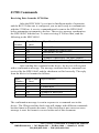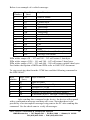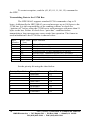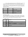
1
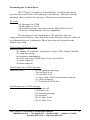
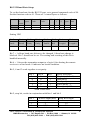
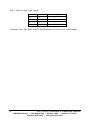
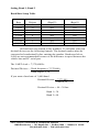
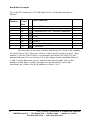
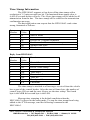
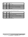
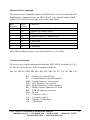
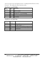
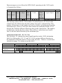
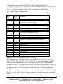
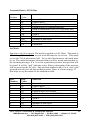
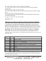
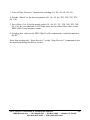
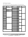
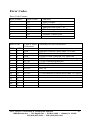
HDV100A3 Command
Response Protocol
Documentation Number: HDV100A3-0812CR
International Headquarters
B&B Electronics Mfg. Co. Inc.
707 Dayton Road -- P.O. Box 1040 -- Ottawa, IL 61350 USA
Phone (815) 433-5100 -- General Fax (815) 433-5105
Home Page: www.bb-elec.com
Sales e-mail: [email protected] -- Fax (815) 433-5109
Technical Support e-mail: [email protected] -- Fax (815) 433-5104
B&B Electronics -- June 2008
HDV100A3 Command & Response Manual
Cover Page
B&B Electronics -- 707 Dayton Rd. -- PO Box 1040 -- Ottawa, IL 61350
PH (815) 433-5100 -- FAX (815) 433-5104
Table of Contents
INTRODUCTION ........................................................................................ 1
OPERATION ............................................................................................... 1
Command Protocol ................................................................................ 2
Formatting the Control Bytes................................................................. 3
DETAILED DESCRIPTION OF GENERAL FUNCTION CODES ....... 4
Command Acknowledgement ................................................................. 4
RS-232 Baud Rate Setup ........................................................................ 5
Setting Baud 1, Baud 2........................................................................... 7
Baud Rate Example ................................................................................ 8
Time Stamp Information ......................................................................... 9
Master Reset Command ....................................................................... 11
Vendor Information .............................................................................. 11
J1708 COMMANDS .................................................................................. 12
Receiving Data from the J1708 Bus ..................................................... 12
Transmitting Data to the J1708 Bus .................................................... 14
Set Filter Active .................................................................................... 15
Set Filter Off......................................................................................... 16
Broadcast Message .............................................................................. 17
J1939 COMMANDS .................................................................................. 19
Start Receive on J1939 Bus .................................................................. 20
Stop Receive on J1939 Bus .................................................................. 20
Arbitration Field (Y1, Y2, Y3, Y4) ........................................................ 21
Transmit Data to J1939 Bus ................................................................ 23
Set Mask ............................................................................................... 23
Set Filter 1 to 4 .................................................................................... 24
J1939 Header Worksheet ..................................................................... 26
ERROR CODES ........................................................................................ 27
HDV100A3 Command & Response Manual
Table of Contents
B&B Electronics -- 707 Dayton Rd. -- PO Box 1040 -- Ottawa, IL 61350
PH (815) 433-5100 -- FAX (815) 433-5104
i
WARNING!
This Model HDV100A3 Converter Module allows
you to connect to active J1708 / J1939 networks.
It is possible that your transmissions through this
converter module could cause malfunction of the
network operation, damage to software or
equipment, or bodily harm.
Do Not Transmit Any Messages to the
network without a complete understanding
of the operation of the network.
B&B Electronics Mfg. Co. specifically disclaims
any responsibility for damage or injury to
software, hardware, equipment or persons as a
result of using this product.
WARNING!
ii
HDV100A3 Command & Response Manual
B&B Electronics -- 707 Dayton Rd. -- PO Box 1040 -- Ottawa, IL 61350
PH (815) 433-5100 -- FAX (815) 433-5104
Introduction
The HDV100A3 works with a command protocol to send and receive data
from J1708/J1587 and J1939 vehicle networks. Networks can be addressed
individually or to/from both at once if they are both present on the vehicle.
Note that the HDV100A3 is powered from the vehicle side of the interface.
If the device is to be used without a vehicle, it will be necessary to connect
power to the device through the 15-pin connector. Positive voltage is
connected on pin 8. Pin 7 is connected to ground.
Operation
The HDV100A3 performs several functions in order to reduce the overhead
and timing requirements of the host application when communicating with
the J1708 and J1939 bus. The device handles collision detection and retries
with no additional interaction from the host application. This greatly reduces
the processor overhead required by the host in order to communicate
efficiently with the vehicle bus.
HDV100A3 Command & Response Manual
B&B Electronics -- 707 Dayton Rd. -- PO Box 1040 -- Ottawa, IL 61350
PH (815) 433-5100 -- FAX (815) 433-5104
1
Command Protocol
The HDV100A3 uses a simple protocol to communicate to vehicle bus. The
protocol is divided into four parts:
Start Of Frame (SOF)
Control Field (shown in light gray)
Data Field (shown in dark gray)
Checksum (CS)
SOF
1 byte
Intelligent Mode Message Structure
Number of
Control Bytes Number of
Control Bytes
Data Bytes
1 byte
1 to 20 bytes
1 byte
Data Bytes
CS
1 to 100 bytes
1 byte
The Start of Frame byte is the first byte in a valid frame and is
always 01 hex.
The Control Field sets up the function and control of the
HDV100A3 hardware and is formatted as shown below.
Control Field Structure
Number of Control ID Byte Function Byte
Bytes to Follow
1 byte
1 byte
1 byte
Control Data Bytes
Up to 20 bytes
The first byte of the Control Field is the number of control bytes in
the message. This value indicates the number of control bytes, excluding
itself, to follow. If the message doesn’t contain any control bytes, the
Number of Control Bytes value will be set to 00 hex as a placeholder.
The next part of the message frame is the data field. The data field
is preceded by the number of data bytes, excluding itself, to follow and is set
to 00 hex if no data is present in the message. The data field is reserved for
data that is to be communicated to the vehicle bus.
Data Field Structure
Number of
Data Bytes
Data Bytes
1 byte
Up to 100 bytes
The last element of a valid message is the checksum. The checksum
is calculated by adding ALL bytes from the Start of Frame (inclusive) to the
last data byte and using the last 8 bits as a checksum.
2
HDV100A3 Command & Response Manual
B&B Electronics -- 707 Dayton Rd. -- PO Box 1040 -- Ottawa, IL 61350
PH (815) 433-5100 -- FAX (815) 433-5104
Formatting the Control Bytes
The 2nd byte is “Number of Control Bytes” to follow and always
precedes the control field. The third byte is the ID byte. This byte tells the
hardware where to direct the message. Valid entries for functions are:
ID Codes
=01 Message for J1708
=02 Message for J1939
=08 General message (for control of the HDV100A3 device)
=05 Device identification (reverse compatible)
The fourth byte is the function byte. The functions that are
supported are listed below. Note that some of the function codes are followed
by additional bytes of information. These bytes must be included in the
control byte count.
Valid General Function Codes
Function codes
=01 change PC baud rate, followed by 3 bytes (UB3, Baud1, Baud2)
=02 send time stamp
=04 hardware handshaking
=08 reset converter, followed by 2 bytes (01,and 02)
=10 time stamp off
=20 time stamp on
Valid Entries for J1708 Functions
Function codes
= 07 set broadcast message
= X8 set filter X off
= X9 set filter X on
= 11 Sync with J1708 bus and start reception
= 10 Stop reception
= 12 Transmit to J1708 bus
Valid Entries for J1939 Functions
Function codes
=00 Receive off
=01 Receive on
=02 Transmit message
=08 Set mask
=X8 set filter X off
=X9 set filter X on
HDV100A3 Command & Response Manual
B&B Electronics -- 707 Dayton Rd. -- PO Box 1040 -- Ottawa, IL 61350
PH (815) 433-5100 -- FAX (815) 433-5104
3
Detailed Description of General Function Codes
Command Acknowledgement
All commands sent to the device will be acknowledged. If no error occurs an
ACK will be sent with the ID byte that accompanied the command. If an
error occurred, a NACK will be sent with the ID byte that accompanied the
command as well as a Function code of $05 and the Error Code. The
responses will not be shown for each command since it is the same for almost
all commands. Below is the format of the ACK/NACK response. If an
ACK/NACK response is different for a particular command, it will be
specified.
ACK/NACK Format:
Byte
Byte
Number
Value
1
01
2
01 or 03
3
aa
4
bb
5
cc
6
00
7
CS
Function
Start of frame
Number of control bytes = 1 for ACK, 3 for NACK
ID byte 08 = internal command
Function code 02 = send time stamp
Number data bytes
Checksum
aa – ID Byte
$01 = J1708 Interface
$02 = J1939 Interface
$05 = Device Id
$08 = RS-232 Interface
$09 = Message Xmit OK Response
bb – FC Byte
None = Command Received and Valid
$05 = A error was detected, NACK
cc – CD Byte
None = No Error Condition
Error Code = See Section 5.10
4
HDV100A3 Command & Response Manual
B&B Electronics -- 707 Dayton Rd. -- PO Box 1040 -- Ottawa, IL 61350
PH (815) 433-5100 -- FAX (815) 433-5104
RS-232 Baud Rate Setup
To set the baud rate for the RS-232 port, set a general command code of 08.
Set the function code to 01. Then set 3 control bytes as follows.
Function Start
of
Frame
Byte # 1
Value
01
Control Command Function UB3 Baud Baud Data Check
Bytes Code
Code
1
2 Bytes Sum
2
05
3
08
4
01
5
6
8
9
00
10
Setting UB3
Bit 7
Divisor
Latch
Bit 6
Set
Break
Bit 5
Set
Parity
Bit 4
Even
Parity
Bit 3
Parity
Enable
Bit 2
Stop
Bits
Bit 1
Word
Length 1
Bit 0
Word
Length 0
Bit 7 = 1 allows baud rate divisor to be changed. 0 baud rate change is
blocked. Bit 7 should not be set. The setting and resetting of this bit is
handled internally.
Bit 6 = 1 forces the transmitter output to a logic 0 for alerting the remote
receiver to a line break. 0 indicates no break condition.
Bit 5, 4 and 3 work together to set parity
Bit 5
*
0
0
1
1
Bit 4
Bit 3
*
0
0
1
1
1
0
1
1
1
*Don’t care state.
Parity Selection
No parity (default)
Odd parity
Even parity
Force parity “1”
Force parity “0”
Bit 2, stop bit, works in conjunction with bits 1 and bit 0
Bit 2
0
1
1
Word Length (bits)
5,6,7,8
5
6,7,8
Stop Bit Length
1 (default)
1½
2
HDV100A3 Command & Response Manual
B&B Electronics -- 707 Dayton Rd. -- PO Box 1040 -- Ottawa, IL 61350
PH (815) 433-5100 -- FAX (815) 433-5104
5
Bits 1 and 0 set the word length
Bit 0
0
0
1
1
Bit 1
0
1
0
1
Word Length
5
6
7
8 (default)
Default value. The HDV100A3 should always be set to 8-bit word length.
6
HDV100A3 Command & Response Manual
B&B Electronics -- 707 Dayton Rd. -- PO Box 1040 -- Ottawa, IL 61350
PH (815) 433-5100 -- FAX (815) 433-5104
Setting Baud 1, Baud 2
Baud Rate Setup Table
Baud
Rate
9600
14400
19200
38,400
57,600
115,200
230,400
460,800
Decimal
Divisor
48
32
24
12
8
4
2
1
Hex Divisor MSB
(Baud 2)
$00
$00
$00
$00
$00
$00 (default)
$00
$00
Hex Divisor LSB
(Baud 1)
$30
$20
$18
$0C
$08
$04 (default)
$02
$01
All baud rates are entered as hex numbers. To calculate your own
decimal divisor use the following formula. The decimal number must be
converted to hexadecimal before entering the number. Baud rates below
9,600 are not recommended because of the difference in speed between the
vehicle bus and PC serial port.
The UART clock = 7,372,800 Hz
Decimal Divisor = Clock frequency ( 7,372,800)
Baud output x 16
If you want a baud rate of 9,600 baud
Decimal Divisor = 7,372,800
9,600 x 16
Decimal Divisor = 48 = 30 hex
Baud 1= 30
Baud 2= 00
HDV100A3 Command & Response Manual
B&B Electronics -- 707 Dayton Rd. -- PO Box 1040 -- Ottawa, IL 61350
PH (815) 433-5100 -- FAX (815) 433-5104
7
Baud Rate Example
To set the PC baud rate to 57,600 baud, N,8,1, format the message as
follows.
Byte
Number
1
2
3
4
5
6
7
8
9
Byte
Value
Hex
01
05
08
01
03
08
00
00
1A
Byte Function
Start of frame
Number of control bytes
Command byte (08 = internal command)
Function Bbte (01 = change baud)
UB3
Baud 1
Baud 2
Number of data bytes
Checksum
The first byte is the start of frame and always 01. Next is the number
of control bytes (05). There are 5 bytes in the control section (in gray). Byte
number 3 sets the HDV100A3 to an internal operation (08). Byte 4 is the
internal function to be executed; (01) is the change baud command. Bytes 5,
6, and 7 set the baud rate, parity, stop bits and word length. Next is the
number of data bytes, in this case there are no data bytes. Last is the
checksum, the value is the 8 bit addition of bytes 1 to 8.
8
HDV100A3 Command & Response Manual
B&B Electronics -- 707 Dayton Rd. -- PO Box 1040 -- Ottawa, IL 61350
PH (815) 433-5100 -- FAX (815) 433-5104
Time Stamp Information
The HDV100A3 supports a four-byte rolling time stamp with a
resolution of 1.5 microseconds per bit. The maximum time stamp value is
6,442.45 seconds before roll over. The 4-byte time stamp will be added to all
transmission from the bus. The time stamp will be added to the transmission
confirmation message.
The host application can request that the HDV100A3 send a time
stamp, formatted as follows.
Byte
Number
1
2
3
4
5
6
Byte
Value
01
02
08
02
00
0D
Function
Start of frame
Number of control bytes
ID byte 08 = internal command
Function code 02 = send time stamp
Number data bytes
Checksum
Reply from HDV100A3
Byte
Number
1
2
3
4
5
6
7
8
9
Byte
Value
01
05
0A
XX
XX
XX
XX
00
CS
Function
Start of frame
Number of control bytes
ID 0A = time stamp
Time msb
Time msb-1
Time msb – 2
Time lsb
Data bytes 00
Checksum
The time stamp is attached to all messages received from the vehicle
bus as part of the control header. After the start of frame byte, the number of
control bytes, ID byte and the next 4 bytes are the time stamp. The fourth
byte is the MSB the seventh byte is the LSB.
Message time stamping is the default condition when the
HDV100A3 is placed in the smart mode. To stop the time stamp from being
added to the J1708 message, send the following command to the
HDV100A3.
HDV100A3 Command & Response Manual
B&B Electronics -- 707 Dayton Rd. -- PO Box 1040 -- Ottawa, IL 61350
PH (815) 433-5100 -- FAX (815) 433-5104
9
Byte
Number
1
2
3
4
5
6
Byte
Value
01
02
08
20
00
2B
Function
Start of frame
Number of control bytes
ID byte 08 = internal command
Function code 20 = stop time stamping
Number data bytes
Checksum
To resume time stamping send the following command:
Byte
Number
1
2
3
4
5
6
Byte
Value
01
02
08
10
00
1B
Function
Start of frame
Number of control bytes
ID byte 08 = internal command
Function code 10 = resume time stamping
Number data bytes
Checksum
Time stamping will resume after reset.
10
HDV100A3 Command & Response Manual
B&B Electronics -- 707 Dayton Rd. -- PO Box 1040 -- Ottawa, IL 61350
PH (815) 433-5100 -- FAX (815) 433-5104
Master Reset Command
The master reset command allows the HDV100A3 to be reset from the PC.
Sending this command resets the HDV100A3 to the default mode (dumb
mode). You will lose all setting sent in the smart mode.
Byte
Number
1
2
3
4
5
6
7
8
Byte
Value
01
04
08
08
01
02
00
18
Function
Start of frame
Number of control bytes
ID byte 08 = internal command
Function code 08= master reset
Check byte
Check byte
Number data bytes
Checksum
Note after sending a master reset the baud rate is 115.2 kbps.
Vendor Information
To receive the vendor information from the HDV100A3 send hex (01, 01,
05, 00, 07) to the device. It will respond as follows:
Hex (01, 0B, 85, MM, DD, MA, M1, M2, MO, 00, VV, VV, 00, DB, CS)
0B = Number of control bytes
85 = Compatibility with other models
MM = Month firmware was created
DD = Day firmware was created
MA = Major firmware revision number
M1 = MSB of minor firmware revision
M2 = LSB of firmware revision
MO = Model
VV = Customer code 1
VV = Customer code 2
DB = Number of data bytes
CS = Checksum
HDV100A3 Command & Response Manual
B&B Electronics -- 707 Dayton Rd. -- PO Box 1040 -- Ottawa, IL 61350
PH (815) 433-5100 -- FAX (815) 433-5104
11
J1708 Commands
Receiving Data from the J1708 Bus
After the HDV100A3 is set into its Intelligent mode of operation
and the RS-232 data rate is configured, you are now ready to communicate
with the J1708 bus. A receive command must be sent to the HDV100A3
before attempting to transmit to the bus. The receive message synchronizes
the HDV100A3 with the bus. To start receiving J1708 bus data, send the
following to the HDV100A3.
Byte
Number
1
2
3
4
5
6
Byte Value
(hex)
01
02
01
11
00
15
Byte Function
Start of frame
The number of control bytes
ID byte 01= J1708
Function code 11 hex start receive
Number of data bytes (00 place holder)
Checksum (bytes 1 through 5 added together)
After sending this command to the device, the device will respond
with a confirmation message. The message confirms that the command was
received by the HDV100A3 and the checksum verified correctly. The reply
from the device is formatted as follows:
Byte
Number
1
2
3
4
5
Byte Value
(hex)
01
01
01
00
03
Byte Function
Start of frame byte
Control byte
ID byte (ID of the sent message)
Number of data bytes
Checksum
The confirmation message is sent in response to a command sent to the
device. The ID byte and the check-sum will change with different commands
but the format will remain the same. If the checksum is not correct an error
message is sent. Its format is covered at the end of this document.
12
HDV100A3 Command & Response Manual
B&B Electronics -- 707 Dayton Rd. -- PO Box 1040 -- Ottawa, IL 61350
PH (815) 433-5100 -- FAX (815) 433-5104
Below is an example of a vehicle message:
Byte
Number
1
2
3
4
5
6
7
8
9
10
11
12
13
14
15
16
Byte Value
(hex)
01
05
01
03
D3
2B
AB
07
80
54
4D
BE
B8
1A
4F
BA
Byte Function
Start of Frame
# of Control Bytes
Control Byte
Timestamp
Timestamp
Timestamp
Timestamp
# of Data Bytes
MID
PID
Data
PID
Data
Data
J1587 Checksum (2’s Compliment)
Message Checksum
PIDs with a range of 0 – 127 and 256 – 383 will return 1 data byte.
PIDs with a range of 128 – 191 and 384 – 447 will return 2 data bytes.
PIDs with a range of 192 – 253 and 448 – 509 will return variable data bytes.
For further description of MIDs and PIDs refer to SAEJ1587 document.
To stop receiving data from the J1708 bus send the following command to
the HDV100A3.
Byte
number
1
2
3
4
5
6
Byte value
(hex)
01
02
01
10
00
14
Byte Function
Start of frame
The number of control bytes
ID byte 01= J1708
Function code 10 hex stop receive
Number of data bytes (00 place holder)
Checksum (bytes 1 through 5 added together)
After sending this command to the device, the device will respond
with a confirmation message and data will cease. Note that there is the
possibility of an incomplete message being sent to the PC after sending this
command. Use the check-sum to verify all messages.
HDV100A3 Command & Response Manual
B&B Electronics -- 707 Dayton Rd. -- PO Box 1040 -- Ottawa, IL 61350
PH (815) 433-5100 -- FAX (815) 433-5104
13
To restart reception, send the (01, 02, 01, 11, 00, 15) command to
the HDV.
Transmitting Data to the J1708 Bus
The HDV100A3 supports standard J1708 commands of up to 21
bytes. Additionally the HDV100A3 can send messages up to 100 bytes to the
J1708 bus. It is the responsibility of the sending software to check for
“ignition off” before using the J1708 bus to send messages with more than 21
bytes to the bus. Failure to check for a “quiet bus” condition before
transmitting a long message may cause erratic bus operation. The format to
send information to the J1708 bus is shown below:
Byte
Number
1
2
3
4
5
6
Byte Value
(hex)
01
03
01
12
02
XX
YY
CS
Byte Function
Start of frame
Number of control bytes
ID bytes 1= J1708
Function code 12 (hex) transmit to J1708 bus
Priority byte 00000010 set bit 0 to 7 see below
Number of data bytes to follow (excludes checksum byte)
Data bytes up to 100 bytes
Checksum
Set the priority bit using the chart below.
Priority Byte Value
1
2
3
4
5
6
7
8
14
Binary Value
00000001
00000010
00000100
00001000
00010000
00100000
01000000
10000000
Hex Value
01
02
04
08
10
20
40
80
HDV100A3 Command & Response Manual
B&B Electronics -- 707 Dayton Rd. -- PO Box 1040 -- Ottawa, IL 61350
PH (815) 433-5100 -- FAX (815) 433-5104
After sending a transmit message to the HDV100A3 you will get the
confirmation message if the checksum is correct. A transmit complete
message is sent to the PC after the device successfully transmits the message
to the J1708 bus. A second message should not be sent to the device before
confirming that the first message has been sent. The transmit confirmation is
formatted as follows:
Byte Number
1
2
3
8
9
Byte Value
(hex)
01
01
09
00
0B
Byte Function
Start of frame
Number of control bytes
ID bytes 9 = transmit OK
Number of data bytes
Checksum
J1708 Message Filter
The J1708 message filter will operate on 4 different MID’s. Only messages
with the same MID as set in the filter will be sent to the PC. The filters will
be OR’ed together so that multiple MID’s can be filtered, MID1 or MID2 or
MID3. The format for the setting of J1708 filtering is as follows:
Set Filter Active
Byte
Byte
Function
Number Value
1
2
3
4
5
6
7
01
03
01
X9
XX
00
CS
Start of frame
Control bytes
ID byte 1 = J1708 message
Set filter 9 = Set filter active
Value of MID to filter On
Data bytes
Checksum
X = filter number 1 to 4
HDV100A3 Command & Response Manual
B&B Electronics -- 707 Dayton Rd. -- PO Box 1040 -- Ottawa, IL 61350
PH (815) 433-5100 -- FAX (815) 433-5104
15
Set Filter Off
Byte
Byte
Number Value
Function
1
2
3
4
6
7
Start of frame
Control bytes
ID byte 1 = J1708 message
Set filter 8 = Set filter inactive
Data bytes
Checksum
01
02
01
X8
00
CS
X = filter number 1 to 4
Setting all filters off will stop all data from the J1708 bus. When all filters
are set off you must send the receive J1708 command to start receiving all
bus messages.
16
HDV100A3 Command & Response Manual
B&B Electronics -- 707 Dayton Rd. -- PO Box 1040 -- Ottawa, IL 61350
PH (815) 433-5100 -- FAX (815) 433-5104
Broadcast Message
The HDV100A3 supports one broadcast message. Once configured by the
host application, this message will be sent repeatedly by the HDV100A3 at a
programmed time interval. This feature is useful to provide a “heartbeat”
function to the J1708 bus with no overhead to the host application’s software.
Sending 0 in the time value stops the broadcast message from being sent.
To start a broadcast message the time interval, message slot,
priority, number of data bytes, and the data must be sent to the HDV100A3.
Once sent, the HDV100A3 will send the message out on the bus at the
specified interval. Existing bus traffic or any bus messages sent to the
HDV100A3 from the host application take priority over a pending broadcast
message.
Once a broadcast message is started the “Stop Broadcast 07”
message must be sent before any changes to the broadcast message can be
made. Changing from one time value (17) to another (37) without stopping
the broadcast will cause the HDV100A3 to act erratically.
Byte
Number
Byte
Value
Function
1
2
3
4
5
6
7
01
04
01
X7
0X
PP
YY
DATA
CS
Start of frame
Control bytes
ID byte 1 = J1708 message
Set broadcast 7 = On
X = Time interval (see chart)
Message slot number (01 only active at this time)
Priority (see chart below)
Data bytes
From 4 to 21 bytes
Checksum
HDV100A3 Command & Response Manual
B&B Electronics -- 707 Dayton Rd. -- PO Box 1040 -- Ottawa, IL 61350
PH (815) 433-5100 -- FAX (815) 433-5104
17
To stop broadcast transmission it is not necessary to send the whole message.
The message below will stop broadcast transmission.
Byte
Number
Byte
Value
Function
1
2
3
4
7
8
01
02
01
07
00
0B
Start of frame
Control bytes
ID byte 1 = J1708 message
Set broadcast 7 = On X = Time interval (see chart)
Data bytes
Checksum
Byte 4 Values
Byte
Value
07
17
27
37
47
Time
Value
Stop broadcast
.5 sec.
1.0 sec
1.5 sec
2.0 sec
Byte 6 (Priority) Values
Byte Value
(hex)
Byte Value
Binary
Priority
01
02
04
08
10
20
40
80
00000001
00000010
00000100
00001000
00010000
00100000
01000000
10000000
1
2
3
4
5
6
7
8
18
HDV100A3 Command & Response Manual
B&B Electronics -- 707 Dayton Rd. -- PO Box 1040 -- Ottawa, IL 61350
PH (815) 433-5100 -- FAX (815) 433-5104
J1939 Commands
The J1939 protocol is similar to the J1708 protocol.
The message starts with Start of Frame byte 01. The number of
control bytes will be 06. The control code for J1939 is 02. The function
codes (XX) are as follows:
00=Sets receive function off
01=Sets receive on
02=Transmits a message with data
04=Set mask
19=filter 1 set on
18=filter 1 set off
29=filter 2 set on
28=filter 2 set off
39=filter 3 set on
38=filter 3 set off
49=filter 4 set on
48=filter 4 set off
Function codes are shown in detail below.
Before operating the HDV100A3 in the J1939 mode it is
recommended that the baud rate be set to 115.2kb. This is done by sending
the following code: (01, 05, 08, 01, 03, 04, 00, 00 16). After sending this
command the baud rate of the sending device (PC) must also be changed.
Because of the difference in baud rates between the J1939 bus and
the RS-232 serial bus, the HDV100A3 may miss messages on the J1939 bus.
This depends on bus load, message length, and filter settings.
Sending any message with a control code of (02) to the J1939 bus
stops the operation on the J1708 bus. If you wish to restart operation on the
J1708 bus you must send the start J1708 reception message (01, 02, 01, 11,
00, 15). Sending this message stops operation on the J1939 bus.
Function codes 00 and 01, Receive OFF, ON operate together to control a
receive register. Sending the command (01, 02, 02, 01, 00, 06) starts
reception on the J1939 bus. This command resets the filter mask to all zeros
(don’t care). All bus traffic is then received. However, it may not be possible
to send all messages to the PC side. Any message that is not serviced before
the next message is received will be overwritten by the new message.
Sending the command (01, 02, 02, 00, 00, 05) turns off the receiver. It is
HDV100A3 Command & Response Manual
B&B Electronics -- 707 Dayton Rd. -- PO Box 1040 -- Ottawa, IL 61350
PH (815) 433-5100 -- FAX (815) 433-5104
19
wise to set the receiver off when not in use. Sending the Start Receive clears
the mask. This renders the filter function useless.
Start Receive on J1939 Bus
Byte
Byte
Function
Number
Value
1
01
Start of frame
2
02
Control bytes
3
02
ID byte 02 = J1939 message
4
01
Function code 01 start reception
5
00
Data bytes
6
06
Checksum
Stop Receive on J1939 Bus
Byte
Number
1
2
3
4
5
6
20
Byte
Value
01
02
02
00
00
05
Function
Start of frame
Control bytes
ID byte 02 = J1939 message
Function code 00 stop reception
Data bytes
Checksum
HDV100A3 Command & Response Manual
B&B Electronics -- 707 Dayton Rd. -- PO Box 1040 -- Ottawa, IL 61350
PH (815) 433-5100 -- FAX (815) 433-5104
Data messages received from the HDV100A3 operating in the J1939 mode,
is formatted as follows:
Control Field
Data Field
Start
# of Contr Time Stamp # of Arbitration
of Control Byte 4 Bytes Data
Field
Frame bytes
Bytes
01
05
02 msb
# of
Data
Bytes
in
Message
lsb ZZ Y1 Y2 Y3 Y4
0X
Bus Data
Up to 8 Bytes
Check
sum
The message starts with 01. The number of control bytes is 05. Next is the
control byte 02, followed by the time stamp, four bytes, with msb first. The
number of data bytes is the number of bytes to follow excluding itself and the
checksum byte. Next is a four byte that contains the arbitration field. J1939
divides this field for different functions show in the chart below. The number
of data bytes sent by the bus is next. This will be a value between 0 and 8.
Next is the bus data followed by the checksum byte.
Arbitration Field (Y1, Y2, Y3, Y4)
The first byte Y1 contains the most significant bits in the J1939 arbitration
field. It is followed by Y2, Y3 and Y4. J1939 assigns different function to
the arbitration field that must be observed by the user. There is a work sheet
included on page 33 to help set up this field.
Arbitration Byte
Arbitration Bit
Y1
Y2
Y3
Y4
7 6 5 4 3 2 1 0 7 6 5 4 3 2 1 0 7 6 5 4 3 2 1 0 7 6 5 4 3 2 1 0
J1939 Arbitration Field 29 28 27 26 25 24 23 22 21 20 19 18 17 16 15 14 13 12 11 10 9 8 7 6 5 4 3 2 1
Bit Position
J1939 Function
Priority R D PDU Format
PDU Specific
Source Address
bits
P
HDV100A3 Command & Response Manual
B&B Electronics -- 707 Dayton Rd. -- PO Box 1040 -- Ottawa, IL 61350
PH (815) 433-5100 -- FAX (815) 433-5104
21
A message received from the HDV will be formatted as follows:
<01><05><02><06><C7><CC><ED><0D><67><80><20><00><08><F0><7D><DA><00>
<00><FF><FF><DA><C9>
The < > are placeholders and are NOT transmitted with the data.
** = value changes with message.
Byte
Number
1
2
3
4
5
Byte
Value
01
05
02
06
C7
Function
6
7
8
9
10
11
12
13
14
15
16
17
18
19
20
21
22
CC
ED
0D
67
80
20
00
08
F0
7D
DA
00
00
FF
FF
DA
C9
Time stamp MSB –2 **
Time stamp LSB **
Number of data bytes to follow (13 dec) **
First byte of arbitration field **
Second byte of arbitration field **
Third byte of arbitration field **
Fourth byte of arbitration field **
Number of data bytes in bus message **
Data bytes **
Data bytes **
Data bytes **
Data bytes **
Data bytes **
Data bytes **
Data bytes **
Data bytes **
Checksum **
Start of frame
Control bytes
ID byte 02 = J1939 message
Time stamp MSB **
Time stamp MSB –1 **
Function code 02 sends data to the J1939 bus.
The transmit code is set up as follows: (01, 06, 02, 02, XX, XX, XX, XX,
DD, YY, YY, YY, YY, YY, YY, YY, YY, CS). The header starts with 01.
There are six control bytes (06). The control code is (02). The transmit
command is (02). The arbitration field is filled out as shown above. There is
also a worksheet to help fill out this field. Next is the number of data bytes in
the data payload. The data payload for the message is entered in the data
field. After a transmission is successfully sent out and confirmed by at least
one active node, an acknowledge message is sent to the PC
(01, 01, 02, 00, 04). There is a form on page 33 to help set up the arbitration
field.
22
HDV100A3 Command & Response Manual
B&B Electronics -- 707 Dayton Rd. -- PO Box 1040 -- Ottawa, IL 61350
PH (815) 433-5100 -- FAX (815) 433-5104
Transmit Data to J1939 Bus
Byte
Number
1
2
3
4
5
6
7
8
9
Byte
Value
01
06
02
02
XX
XX
XX
XX
DD
DATA
CS
Function
Start of frame
Control bytes
ID byte 1 = J1708 message
Function byte 02 transmit message
MSB of arbitration field (J1939 priority bits)
MSB-1
MSB-2
LSB of arbitration field (J1939 source address)
Number of data bytes
From 0 to 8 bytes
Checksum
Set Mask
Function code 04 set mask. The mask is applied to ALL filters. The mask is
32 bits long. The last 3 bits are not used and must be set to zero. This mask
covers the 29-bit arbitration field. To use the filter function, the mask must
be set. The mask determines what position(s) will be tested and matched to
the incoming message. If a 1 is set in a particular position, that position will
be tested. It will be “and” with any active filters to determine if the message
will be passed to the PC side. Any position marked with a 0 is a “don’t care”
position and will pass all data in that position. There is a form on page 33
that helps set up the mask for the arbitration field.
Byte
Number
1
2
3
4
5
6
7
8
9
10
Byte
Value
01
06
02
04
XX
XX
XX
XX
00
CS
Function
Start of frame
Control bytes
ID byte 02 = J1939
Function byte 04 set mask
MSB of arbitration field (J1939 priority bits)
MSB-1
MSB-2
LSB of arbitration field (J1939 source address)
Number of data bytes
Checksum
HDV100A3 Command & Response Manual
B&B Electronics -- 707 Dayton Rd. -- PO Box 1040 -- Ottawa, IL 61350
PH (815) 433-5100 -- FAX (815) 433-5104
23
The mask can be used to look at a group of messages:
To set the mask to filter on the J1939 priority field, the mask would be
loaded with:
(01, 06, 02, 04, E0, 00, 00, 00, 00, ED)
To set the mask to filter on the J1939 PGN field, the mask would be loaded
with:
(01, 06, 02, 04, 07, FF, F8, 00, 00, 0B)
To set mask to filter on both the priority field and the PGN field the mask
would be loaded with:
(01, 06, 02, 04, B7, FF, F8, 00, 00, BB)
Set Filter 1 to 4
Function codes 18 and 19, 28 and 29, 38 and 39, 48 and 49 are filter pairs.
These filters are set by sending the desired arbitration code to each filter, 1 to
4. The filters work with the mask function. If the mask is set to zero in a
position (don’t care) the value of the filter in that position doesn’t matter.
The filter arbitration field is set to match the aberration code of the incoming
message. A match of the filter “and” the mask will pass the message to the
PC. The X9 sets the filter On; X8 sets the filter Off, where X=1 through 4.
Important: the receiver and each filter must have a different arbitration
code. If the receiver and a filter are given the same arbitration code the
controller may become erratic. It will need to be powered-off reset to recover
from this error.
Byte
Number
1
2
3
4
5
6
7
8
9
10
Byte
Value
01
06
02
YY
XX
XX
XX
XX
00
CS
Function
Start of Frame
Control bytes
ID byte = J1708 message
Function byte (18 or 19) (28 or 29) (38 or 39) (48 or 49)
MSB of arbitration field (J1939 priority bits)
MSB-1
MSB-2
LSB of arbitration field (J1939 source address)
Number of data bytes
Checksum
To use the HDV100A3, the filter for a particular J1939 PGN the following
procedure must be followed.
24
HDV100A3 Command & Response Manual
B&B Electronics -- 707 Dayton Rd. -- PO Box 1040 -- Ottawa, IL 61350
PH (815) 433-5100 -- FAX (815) 433-5104
1. Turn off the “Receive” function by sending (01, 02, 02, 00, 00, 05).
2. Set the “Mask” to the desired pattern (01, 06, 02, 04, XX, XX, XX, XX,
00, CS).
3. Set a filter (1 to 4) to the match value (01, 06, 02, YY, XX, XX, XX, XX,
00, CS). Be sure that this is NOT the same as any other filter value or the
HDV100A3 may become erratic.
4. Sending this value to the HDV100A3 will continuously send this match to
the PC.
Note that sending the “ Start Receive” or the “Stop Receive” command resets
the mask rendering the filters useless.
HDV100A3 Command & Response Manual
B&B Electronics -- 707 Dayton Rd. -- PO Box 1040 -- Ottawa, IL 61350
PH (815) 433-5100 -- FAX (815) 433-5104
25
J1939 Header Worksheet
This worksheet will aid in filling out/decoding the J1939 arbitration field.
Bit
Number
29
28
27
26
25
24
23
22
21
20
19
18
17
16
15
14
13
12
11
10
9
8
7
6
5
4
3
2
1
J1939
Function
Priority Bits
CAN Frame
Entry
Reserved
Data Page
PDU-Format
(PGN Byte 2)
0
0
Hex
Value
Byte 1
Byte 2
PDU Specific
(PGN Byte 3)
Byte 3
Source Address
Byte 4
0
0
0
26
HDV100A3 Command & Response Manual
B&B Electronics -- 707 Dayton Rd. -- PO Box 1040 -- Ottawa, IL 61350
PH (815) 433-5100 -- FAX (815) 433-5104
Error Codes
Error Code Format:
Byte Number
Byte Value
1
01
2
03
3
05
4
XY
5
0Z
6
00
7
CS
Error Code
DEC
1
2
3
4
5
6
7
8
9
10
11
12
13
14
15
HEX
1
2
3
4
5
6
7
8
9
A
B
C
D
E
F
Function
Start of frame
Number of control bytes
Function code error = 05
ID of message that caused error
Error code (see chart below)
Number of data bytes
Checksum
Type of Error
Generated
Meaning of Error Generated
Gen
Gen
Gen
J1708
J1708
J1708
Inbuffer overflow; more than 127 bytes
Checksum mismatch
Protocol error; function, ID, code bad
J1708 input buffer full missed bus message
J1708 command unknown
J1708 output buffer full
J1939
Bus off
J1708
J1708 inbuffer overflow more than 127 bytes
HDV100A3 Command & Response Manual
B&B Electronics -- 707 Dayton Rd. -- PO Box 1040 -- Ottawa, IL 61350
PH (815) 433-5100 -- FAX (815) 433-5104
27