1
Industrial Flat Panel IFP1500, IFP1900, ___________________
Preface
IFP2200
1
___________________
Overview
SIMATIC
2
___________________
Safety information
Industrial Monitors
Industrial Flat Panel IFP1500,
IFP1900, IFP2200
Operating Instructions
Installing and connecting the
3
___________________
device
___________________
4
Commissioning the device
___________________
5
Operating the device
Maintaining and servicing
___________________
6
your device
___________________
7
Technical information
___________________
A
Technical Support
___________________
B
List of abbreviations
11/2014
A5E31298376-AC
Legal information
Warning notice system
This manual contains notices you have to observe in order to ensure your personal safety, as well as to prevent
damage to property. The notices referring to your personal safety are highlighted in the manual by a safety alert
symbol, notices referring only to property damage have no safety alert symbol. These notices shown below are
graded according to the degree of danger.
DANGER
indicates that death or severe personal injury will result if proper precautions are not taken.
WARNING
indicates that death or severe personal injury may result if proper precautions are not taken.
CAUTION
indicates that minor personal injury can result if proper precautions are not taken.
NOTICE
indicates that property damage can result if proper precautions are not taken.
If more than one degree of danger is present, the warning notice representing the highest degree of danger will
be used. A notice warning of injury to persons with a safety alert symbol may also include a warning relating to
property damage.
Qualified Personnel
The product/system described in this documentation may be operated only by personnel qualified for the specific
task in accordance with the relevant documentation, in particular its warning notices and safety instructions.
Qualified personnel are those who, based on their training and experience, are capable of identifying risks and
avoiding potential hazards when working with these products/systems.
Proper use of Siemens products
Note the following:
WARNING
Siemens products may only be used for the applications described in the catalog and in the relevant technical
documentation. If products and components from other manufacturers are used, these must be recommended
or approved by Siemens. Proper transport, storage, installation, assembly, commissioning, operation and
maintenance are required to ensure that the products operate safely and without any problems. The permissible
ambient conditions must be complied with. The information in the relevant documentation must be observed.
Trademarks
All names identified by ® are registered trademarks of Siemens AG. The remaining trademarks in this publication
may be trademarks whose use by third parties for their own purposes could violate the rights of the owner.
Disclaimer of Liability
We have reviewed the contents of this publication to ensure consistency with the hardware and software
described. Since variance cannot be precluded entirely, we cannot guarantee full consistency. However, the
information in this publication is reviewed regularly and any necessary corrections are included in subsequent
editions.
Siemens AG
Industry Sector
Postfach 48 48
90026 NÜRNBERG
GERMANY
A5E31298376-AC
Ⓟ 11/2014 Subject to change
Copyright © Siemens AG 2014.
All rights reserved
Preface
These operating instructions contain all the information you need for commissioning and
operation of the SIMATIC Industrial Flat Panel IFP.
It is intended both for programming and testing personnel who commission the device and
connect it with other units (automation systems, programming devices), as well as for service
and maintenance personnel who install add-ons or carry out fault/error analyses.
Basic knowledge required
A solid background in personal computers and Microsoft operating systems is required to
understand this manual. General knowledge in the field automation control engineering is
recommended.
Scope of the operating instructions
These operating instructions apply to all IFP1500, IFP1900 and IFP2200 Industrial Flat
Panels with the order numbers 6AV7863-....
Scope of this documentation
The SIMATIC Industrial Flat Panel is supplied with the following documents:
● In printed form: Quick Install Guide SIMATIC IFP1500, IFP1900, IFP2200, Installation
and Commissioning Instructions
● Electronically as PDF file on the "Documentation and Drivers" CD/DVD:
– SIMATIC IFP1500, IFP1900, IFP2200 Operating Instructions
– Operating Manual SIMATIC IPC Wizard
You can find the operating manual in the IPC Wizard installation directory after
installing the IPC Wizard.
Conventions
In these operating instructions, the SIMATIC IFP is also referred to as "Flat Panel" or
"device".
At some places in these operating instructions, the general term "Windows Embedded
Standard" is used to refer to "Windows Embedded Standard 2009" and "Windows
Embedded Standard 7". "Windows 7" is used as an abbreviation for "Windows 7 Ultimate".
A touch device generally refers to a device with a touch screen, as opposed to a pure
"display device". Touch screen is the general term for a capacitive multi-touch screen and
resistive single touch screen.
Industrial Flat Panel IFP1500, IFP1900, IFP2200
Operating Instructions, 11/2014, A5E31298376-AC
3
Preface
Figures
This manual contains figures of the described devices. The supplied device may differ in
some details from the figures. Within some of the figures, one device is used to represent all
Industrial Flat Panels.
History
The following earlier release versions of these operating instructions have been published:
Edition
Comment
09/2012
First Edition
06/2014
Description of devices with capacitive multi-touch screen
11/2014
Update with IPC Wizard 2.1 and corrections
Industrial Flat Panel IFP1500, IFP1900, IFP2200
4
Operating Instructions, 11/2014, A5E31298376-AC
Table of contents
Preface ................................................................................................................................................... 3
1
Overview................................................................................................................................................. 7
1.1
1.2
1.3
1.3.1
1.3.2
1.3.3
1.3.4
1.3.4.1
1.3.4.2
1.4
2
Safety information ................................................................................................................................. 17
2.1
2.2
3
General safety instructions .....................................................................................................17
Notes about usage ..................................................................................................................19
Installing and connecting the device ...................................................................................................... 21
3.1
3.1.1
3.1.2
3.1.3
3.1.4
3.1.5
3.2
3.2.1
3.2.2
3.2.3
3.2.4
3.3
3.3.1
3.3.2
3.3.3
3.3.4
3.3.4.1
3.3.4.2
3.3.5
3.3.5.1
3.3.5.2
3.3.6
3.3.7
4
Product description ................................................................................................................... 7
Scope of delivery ...................................................................................................................... 9
Construction of the devices ....................................................................................................10
IFP1500, IFP1900, IFP2200 Multitouch..................................................................................10
IFP1500, IFP1900, IFP2200 Touch ........................................................................................12
IFP1500 Touch/Key ................................................................................................................13
Interfaces ................................................................................................................................14
Standard versions ...................................................................................................................14
Extended versions ..................................................................................................................14
Accessories .............................................................................................................................15
Preparing for installation .........................................................................................................21
Checking the delivery package ...............................................................................................21
Permitted mounting positions .................................................................................................22
Checking clearances...............................................................................................................24
Preparing the mounting cutout ................................................................................................25
Labeling the function keys ......................................................................................................26
Mounting the device ................................................................................................................28
Notes on installation................................................................................................................28
Mounting clips or mounting brackets, position for IP65 ..........................................................29
Fastening the device with mounting clips or mounting brackets ............................................31
Position of the mounting clips for IP66 ...................................................................................32
Connecting the device ............................................................................................................33
Overview .................................................................................................................................33
Notes on connection ...............................................................................................................35
Connecting the protective earth ..............................................................................................36
Connecting the power supply .................................................................................................37
Connecting the DC power supply ...........................................................................................37
Connecting an AC power supply ............................................................................................39
Connecting the device to a PC ...............................................................................................41
Standard version .....................................................................................................................41
Extended version ....................................................................................................................41
Connecting a USB device .......................................................................................................41
Securing the cables ................................................................................................................42
Commissioning the device .................................................................................................................... 43
4.1
4.2
4.2.1
4.2.1.1
4.2.1.2
General information on commissioning ..................................................................................43
Notes on various device configurations ..................................................................................44
SIMATIC IPC Wizard 2.1 ........................................................................................................44
System requirements ..............................................................................................................44
Installing IPC Wizard...............................................................................................................45
Industrial Flat Panel IFP1500, IFP1900, IFP2200
Operating Instructions, 11/2014, A5E31298376-AC
5
Table of contents
5
Operating the device ............................................................................................................................. 47
5.1
Operator input options ........................................................................................................... 47
5.2
Operating a device with resistive single touch screen ........................................................... 48
5.3
Operating a device with capacitive multi-touch screen .......................................................... 49
5.4
Operating a Touch/Key device............................................................................................... 51
5.5
IPC Wizard functions ............................................................................................................. 53
6
Maintaining and servicing your device ................................................................................................... 55
6.1
6.2
6.3
7
A
Technical information ............................................................................................................................ 57
7.1
7.1.1
Certificates and approvals ..................................................................................................... 57
Programmable logic controllers ............................................................................................. 60
7.2
7.2.1
7.2.2
Directives and declarations .................................................................................................... 60
ESD guideline ........................................................................................................................ 60
Electromagnetic compatibility ................................................................................................ 62
7.3
7.3.1
7.3.2
7.3.3
7.3.4
7.3.5
7.3.6
7.3.7
7.3.8
7.3.9
Dimension drawings ............................................................................................................... 63
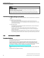
Dimension drawing of the IFP1500 Multitouch ...................................................................... 63
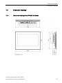
Dimension drawing of the IFP1500 Monitor and Touch ........................................................ 64
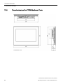
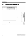
Dimension drawing of the IFP1900 Multitouch ...................................................................... 65
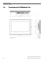
Dimension drawing of the IFP1900 Monitor and Touch ........................................................ 66
Dimension drawing of the IFP2200 Multitouch ...................................................................... 67
Dimension drawing of the IFP2200 Monitor and Touch ........................................................ 68
Dimension drawing of the IFP1500 Touch/Key ..................................................................... 69
Dimension drawing Host Unit USB ........................................................................................ 70
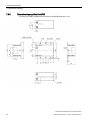
Dimensions for labeling strips ................................................................................................ 71
7.4
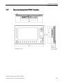
Rating plate ............................................................................................................................ 72
7.5
7.5.1
7.5.2
7.5.2.1
7.5.2.2
7.5.2.3
Technical specifications ......................................................................................................... 73
General technical specifications ............................................................................................ 73
Ambient conditions ................................................................................................................. 75
Transport and storage conditions .......................................................................................... 75
Operating conditions .............................................................................................................. 76
Information on insulation tests, protection class and degree of protection ............................ 79
7.6
7.6.1
7.6.2
7.6.3
7.6.4
7.6.5
Interface description ............................................................................................................... 80
24 V DC Power Supply .......................................................................................................... 80
DVI-D interface....................................................................................................................... 81
DisplayPort ............................................................................................................................. 82
USB interface, Type B ........................................................................................................... 83
USB hub, Type A ................................................................................................................... 83
Technical Support ................................................................................................................................. 85
A.1
B
Cleaning the device ............................................................................................................... 55
Spare parts and repairs ......................................................................................................... 56
Recycling and disposal .......................................................................................................... 56
Service and support ............................................................................................................... 85
List of abbreviations .............................................................................................................................. 87
Glossary ............................................................................................................................................... 89
Index .................................................................................................................................................... 91
Industrial Flat Panel IFP1500, IFP1900, IFP2200
6
Operating Instructions, 11/2014, A5E31298376-AC
1
Overview
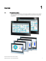
1.1
Product description
SIMATIC Industrial Flat Panels are LCD monitors suitable for industrial use with a brilliant
TFT display which can be connected to all SIMATIC IPCs as well as almost all generally
available PCs.
Industrial Flat Panel IFP1500, IFP1900, IFP2200
Operating Instructions, 11/2014, A5E31298376-AC
7
Overview
1.1 Product description
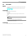
Features of SIMATIC Industrial Flat Panels
● Rugged front
● Brilliant TFT display with a wide reading angle;
Resistive single touch screen in sizes 15", 19" and 22"
Capacitive multi-touch screen available in sizes 15", 19" and 22"
● Available as pure display device (monitor) or touch device
● Can be placed up to 5 m from the IPC
● DVI-D and DisplayPort V1.1 interface
● Multi-monitoring support
● Backlighting can be dimmed via software
● 24 V DC power supply
● Degree of protection IP65 in installed state
● Enclosure type: Front face only Type 4X/Type 12 (indoor use only)
● Up to 16 million colors
Additional features of the Extended versions
● Up to 30 m away from PC possible via DVI
● Power supply (with USB) 24 V DC and 100-240 V AC
● 2 USB ports
● Also available as touch/key version with front USB interface
Industrial Flat Panel IFP1500, IFP1900, IFP2200
8
Operating Instructions, 11/2014, A5E31298376-AC
Overview
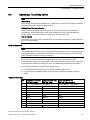
1.2 Scope of delivery
1.2
Scope of delivery
The product package includes the following components:
Name
Figure
Number
Industrial Flat Panel
1
Installation instructions
1
(Quick Install Guide)
"Mounting clips and power supply
plugs" accessory kit
12
1
"Connecting cables" accessory kit
DVI connecting cable
1
2 m in length, for commissioning
USB connecting cable, 2 m 1
Power supply cable 230 V AC
"Documentation and Drivers" CD
1
2
1
2
1
1
Not with standard display device (monitor)
Only for devices with AC power supply
Industrial Flat Panel IFP1500, IFP1900, IFP2200
Operating Instructions, 11/2014, A5E31298376-AC
9
Overview
1.3 Construction of the devices
1.3
Construction of the devices
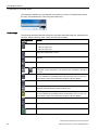
1.3.1
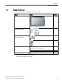
IFP1500, IFP1900, IFP2200 Multitouch
This section describes the design of the multi-touch devices, using the IFP1900 Multitouch
as an example.
Front view and side view
①
②
③
Display/touch screen
Recesses for mounting clips
Mounting seal
Industrial Flat Panel IFP1500, IFP1900, IFP2200
10
Operating Instructions, 11/2014, A5E31298376-AC
Overview
1.3 Construction of the devices
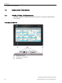
Rear view
①
②
③
④
Rating plate
Interface name
Equipotential bonding
Retaining elements for strain relief of the connecting cables
Industrial Flat Panel IFP1500, IFP1900, IFP2200
Operating Instructions, 11/2014, A5E31298376-AC
11
Overview
1.3 Construction of the devices
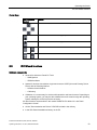
1.3.2
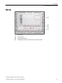
IFP1500, IFP1900, IFP2200 Touch
This section describes the design of the monitor and touch devices, using the IFP1500
Touch as an example.
Front view and side view
①
②
③
Display/touch screen
Recesses for mounting clips
Mounting seal
Rear view
See section "IFP1500, IFP1900, IFP2200 Multitouch".
Industrial Flat Panel IFP1500, IFP1900, IFP2200
12
Operating Instructions, 11/2014, A5E31298376-AC
Overview
1.3 Construction of the devices
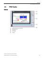
1.3.3
IFP1500 Touch/Key
Front view
①
②
③
④
⑤
Display and function keys with LED
Alphanumeric keys
Control keys
Cursor keys
USB port
Industrial Flat Panel IFP1500, IFP1900, IFP2200
Operating Instructions, 11/2014, A5E31298376-AC
13
Overview
1.3 Construction of the devices
1.3.4
Interfaces
1.3.4.1
Standard versions
①
②
③
④
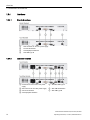
1.3.4.2
X80 connector for 24 V DC power supply
X71 DVI-D interface
X70 DisplayPort interface
X60 USB Type B
Extended versions
①
②
③
④
Connection for 100 to 240 V AC power
supply
X80 connector for 24 V DC power supply
X71 DVI-D interface
⑤
X61/X62 USB Type A
⑥
⑦
X63 USB link interface
X60 USB Type B
X70 DisplayPort interface
Industrial Flat Panel IFP1500, IFP1900, IFP2200
14
Operating Instructions, 11/2014, A5E31298376-AC
Overview
1.4 Accessories
1.4
Accessories
This section contains the number of accessories available at the time of publication of the
operating instructions. You will find additional accessories on the Internet at:
● Industry Mall (https://mall.industry.siemens.com)
● Expansion components and accessories (http://www.automation.siemens.com/mcms/pcbased-automation/en/industrial-pc/expansion_components_accessories)
All Industrial Flat Panels
Name
Specification
Order number
DVI line
3 m long
6AV7860-0BH30-0AA0
5 m long
6AV7860-0BH50-0AA0
3 m long
6AV7860-0DH30-0AA0
5 m long
6AV7860-0DH50-0AA0
3 m long
6AV7860-0CH30-0AA0
5 m long
6AV7860-0CH50-0AA0
15"
6AV2124-6QJ00-0AX0
19"
6AV2124-6UJ00-0AX0
22"
6AV2124-6XJ00-0AX0
Mounting clips service pack
20 pieces
6AV6671-8XK00-0AX3
Mounting brackets service pack
2 x 8 latch fasteners
6AV7672-1JC00-0AA0
Touch pen
only for devices with resistive single
touch screen
6AV7672-1JB00-0AA0
Name
Specification
Order number
Cable set (DVI/USB cable)
10 m long
6AV7860-1EX21-0AA1
15 m long
6AV7860-1EX21-5AA1
20 m long
6AV7860-1EX22-0AA1
30 m long
6AV7860-1EX23-0AA1
DisplayPort line
USB line
Protective foil for the touch screen
Extended version
Touch/Key Extended version
Name
Film for labeling the function keys
(slide-in labels)
Order number
Print templates for the slide-in labels
are available on the "Documentation
and Drivers" CD/DVD.
6AV7672-0DA00-0AA0
Industrial Flat Panel IFP1500, IFP1900, IFP2200
Operating Instructions, 11/2014, A5E31298376-AC
15
Overview
1.4 Accessories
Industrial Flat Panel IFP1500, IFP1900, IFP2200
16
Operating Instructions, 11/2014, A5E31298376-AC
Safety information
2.1
2
General safety instructions
Open equipment and the Machinery Directive
WARNING
The device constitutes open equipment
The device constitutes open equipment. This means that the device may only be installed
in enclosures or cabinets which provide front access for operating the device.
Access to the enclosure or cabinet in which the device is installed should only be possible
by means of a key or tool and for trained and authorized personnel.
Electrocution risk when control cabinet is open
When you open the control cabinet, there may be a dangerous voltage at certain areas or
components.
Touching these areas or components can cause electrocution.
Always disconnect the cabinet from the mains before opening it.
The device may only be used in machines which comply with the Machinery Directive
The Machinery Directive specifies precautions to be taken when commissioning and
operating machinery within the European Economic Area.
Failure to follow these precautions is a breach of the Machinery Directive. Such failure may
also cause personal injury and damage depending on the machine operated.
The machine in which the HMI device is to be operated must conform to Directive
2006/42/EC.
Hazardous areas
When operating the HMI device in hazardous areas the following warning applies.
WARNING
Explosion Hazard
Do not disconnect while circuit is live unless area is known to be non-hazardous.
Substitution of components may impair suitability for Class I, Division 2 or Zone 2.
Risque d'Explosion
Ne pas déconnecter pendant que le circuit est sous tension, sauf si la zone est nondangereuse. Le remplacement de composants peut compromettre leur capacité à satisfaire
à la Classe I, Division 2 ou Zone 2.
Industrial Flat Panel IFP1500, IFP1900, IFP2200
Operating Instructions, 11/2014, A5E31298376-AC
17
Safety information
2.1 General safety instructions
High frequency radiation
NOTICE
Unwanted operating states
High-frequency radiation, for example from cellular phones, interferes with device functions
and can cause device malfunction.
This causes injury and damages the system.
Avoid high-frequency radiation:
• Remove the sources of radiation from the vicinity of the device.
• Switch off radiating devices.
• Reduce the radio output of radiating devices.
• Observe the information on electromagnetic compatibility (Page 76).
Industrial Security
Siemens offers products and solutions with Industrial Security functions that support the safe
operation of equipment, solutions, machines, devices and/or networks. They are important
components in a comprehensive Industrial Security concept. As a result the products and
solutions from Siemens are constantly evolving. Siemens recommends obtaining regular
information regarding product updates.
For safe operation of Siemens products and solutions appropriate protective measures (e.g.,
cell protection concept) must be taken and each component must be integrated in a
comprehensive Industrial Security concept, which corresponds with the current state of
technology. The products of other manufacturers need to be taken into consideration if they
are also used. You can find addition information on Industrial Security under
(http://www.siemens.com/industrialsecurity).
Sign up for our product-specific newsletter to receive the latest information on product
updates. For more information, see under (http://www.siemens.de/automation/csi_en_WW).
Disclaimer for third-party software updates
This product includes third-party software. Siemens AG only provides a warranty for
updates/patches of the third-party software, if these have been distributed as part of a
Siemens software update service contract or officially released by Siemens AG. Otherwise,
updates/patches are undertaken at your own risk. You can find more information about our
Software Update Service offer on the Internet at Software Update Service
(http://www.automation.siemens.com/mcms/automation-software/en/software-updateservice/Pages/Default.aspx).
Notes on protecting administrator accounts
A user with administrator privileges has extensive access and manipulation options in the
system.
Therefore, ensure there are adequate safeguards for protecting the administrator accounts
to prevent unauthorized changes. To do this, use secure passwords and a standard user
account for normal operation. Other measures, such as the use of security policies, should
be applied as needed.
Industrial Flat Panel IFP1500, IFP1900, IFP2200
18
Operating Instructions, 11/2014, A5E31298376-AC
Safety information
2.2 Notes about usage
2.2
Notes about usage
NOTICE
Device is approved for indoor use only
The device may be damaged if operated outdoors.
• "Indoor use only"
• Operate the device indoors only.
Industrial applications
The device is designed for industrial use. It conforms to the following standards:
● Requirements of the emission standard for industrial environments, EN 61000-6-4: 2007
● Requirements for interference immunity EN 61000-6-2: 2005
● Immunity to interference acc. to EN 55024
● Radio interference suppression acc. to EN 55022, Class B
Use in residential areas
Note
Device is not intended for use in residential areas
The device is not intended for use in residential areas. Operating the device in residential
areas can affect radio or TV reception.
If you operate the device in a residential area, you must ensure conformance to Class B
limits according to EN 55011 regarding the emission of radio interference.
Suitable measures for achieving the degree of noise suppression for Limit Class B include,
for example:
● Installation of the device in grounded control cabinets
● Use of filters in electrical supply lines
Individual acceptance is required.
Risk analysis and measures
WARNING
Hazards emanating from unprotected machines or plants
The results of a risk analysis can reveal any hazards emanating from unprotected
machinery. Such hazards may pose a risk of personal injury.
You can prevent personal injury caused by hazards as specified in the risk analysis by
taking the following measures:
• Installing additional protective devices on machinery and plants. In particular, it must
also be ensured that the programming, configuration and wiring of all I/Os used takes
place in accordance with the safety performance (SIL, PL or Cat.) identified by the
requisite risk analysis.
• Use of the device in accordance with its intended purpose, which can be verified by
means of a system function test. This test can detect programming, configuration and
wiring errors.
• Documentation of the test results, which must be entered in the relevant safety reports if
required.
Industrial Flat Panel IFP1500, IFP1900, IFP2200
Operating Instructions, 11/2014, A5E31298376-AC
19
Safety information
2.2 Notes about usage
Environment
NOTICE
Ambient conditions and chemical resistance
Ambient conditions not suited for the device can adversely affect operation. Chemical
agents, such as detergents or operating material, can change the color, shape and
structure of the device surface. The device may be damaged. This may lead to
malfunctions.
For this reason, the following precautionary measures should be taken:
• Only operate the device in closed rooms. Failure to comply with these instructions will
render the warranty null and void.
• Only operate the device in the ambient conditions specified in the technical
specifications.
• Protect the device against dust, moisture and heat.
• The device may not be used in harsh operating environments, such as areas subject to
acidic vapors or gases, without additional protective measures (e.g. a clean air supply).
• Only use suitable detergents. Only use suitable detergents. Read the information about
Chemical resistance of the HMI devices and industrial PCs
(http://support.automation.siemens.com/WW/view/en/39718396) on the Internet.
TFT displays
NOTICE
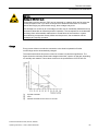
Burn-in effect and backlight
A permanent picture with bright images can result in a burn-in effect. The longer the same
content is displayed on the screen, the longer it will take for the burn-in effect to disappear.
Screen savers that use active black when the backlight is on reduce the burn-in effect. The
brightness of the backlight decreases incrementally during operational life.
• Activate the screen saver, for example, "starfield simulation".
You can extend the service life of the display and the backlight with the following measures:
• Reduce the backlight.
• Pay attention to the length of time the backlight is activated.
Additional information is available in the section "General Technical Specifications".
Defective pixels in the display
The manufacturing process of modern displays does not currently guarantee that all pixels of
the display are perfect. It is therefore inevitable that the display will contain a small number
of defective pixels. This does not limit the function in any way provided the defective pixels
are not all in one location.
Additional information is available in the section "General Technical Specifications".
Industrial Flat Panel IFP1500, IFP1900, IFP2200
20
Operating Instructions, 11/2014, A5E31298376-AC
Installing and connecting the device
3.1
Preparing for installation
3.1.1
Checking the delivery package
3
Procedure
1. When accepting a delivery, please check the packaging for visible transport damage.
2. If any transport damage is present at the time of delivery, lodge a complaint at the
shipping company in charge. Have the shipper confirm the transport damage
immediately.
3. Unpack the device at its installation location.
4. Keep the original packaging in case you have to transport the unit again.
Note
Damage to the device during transport and storage
If a device is transported or stored without packaging, shocks, vibrations, pressure and
moisture may impact the unprotected unit. Damaged packaging indicates that ambient
conditions have already had a massive impact on the device and it may be damaged.
This may cause the device, machine or plant to malfunction.
• Keep the original packaging.
• Pack the device in the original packaging for transportation and storage.
5. Check the contents of the packaging and any accessories you may have ordered for
completeness and damage.
6. Please inform the delivery service immediately if the package contents are incomplete or
damaged or do not correspond with your order. Fax the enclosed form "SIMATIC IPC/PG
Quality Control Report".
WARNING
Electric shock and fire hazard due to damaged device
A damaged device can be under hazardous voltage and trigger a fire in the machine or
plant. A damaged device has unpredictable properties and states.
Death or serious injury could occur.
Make sure that the damaged device is not inadvertently installed and put into operation.
Label the damaged device and keep it locked away. Send off the device for immediate
repair.
Industrial Flat Panel IFP1500, IFP1900, IFP2200
Operating Instructions, 11/2014, A5E31298376-AC
21
Installing and connecting the device
3.1 Preparing for installation
NOTICE
Damage from condensation
If the device is subjected to low temperatures or extreme fluctuations in temperature
during transportation, as is the case in cold weather, for example, moisture can build up
on or inside the device (condensation).
Moisture causes a short circuit in electrical circuits and damages the device.
In order to prevent damage to the device, proceed as follows:
• Store the device in a dry place.
• Bring the device to room temperature before starting it up.
• Do not expose the device to direct heat radiation from a heating device.
• If condensation develops, wait approximately 12 hours or until the device is
completely dry before switching it on.
7. Please keep the enclosed documentation in a safe place. It belongs to the device. You
need the documentation when you commission the device for the first time.
8. Write down the identification data of the device.
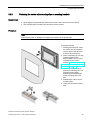
3.1.2
Permitted mounting positions
The device is suitable for installation in:
● Mounting cabinets
● Control cabinets
● Switchboards
● Consoles
In the following, all of these mounting options are referred to by the general term "cabinet".
The device is self-ventilated and approved for inclined mounting at angles up to +/-35° in
stationary cabinets.
NOTICE
Damage due to overheating
Inclined installation reduces the convection by the device and therefore the maximum
permitted ambient temperature for operation.
If there is sufficient forced ventilation, the device can also be operated in the inclined
mounting position up to the maximum permitted ambient temperature for vertical
installation. The device may otherwise be damaged and its certifications and warranty will
be rendered null and void.
For information on permitted ambient temperatures, refer to the section Technical
specifications (Page 73).
Industrial Flat Panel IFP1500, IFP1900, IFP2200
22
Operating Instructions, 11/2014, A5E31298376-AC
Installing and connecting the device
3.1 Preparing for installation
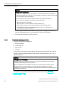
Mounting position
Select one of the approved mounting positions for your device. The approved mounting
positions are described in the following sections.
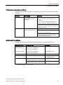
Mounting in horizontal format
All devices are suitable for horizontal mounting positions.
A maximum ambient temperature of +50 °C is permitted for vertical mounting of the IFP1500
(0° tilt angle); a maximum of +40 °C is permitted for inclined mounting.
The ambient temperature for the IFP1900 and IFP2200 when installed vertically should not
exceed +45 °C.
Mounting in vertical format
All monitor and touch versions also support vertical mounting.
A maximum ambient temperature of +40 °C is permissible for vertical mounting (0° tilt angle);
a maximum of +35 °C is permitted for inclined mounting.
Industrial Flat Panel IFP1500, IFP1900, IFP2200
Operating Instructions, 11/2014, A5E31298376-AC
23
Installing and connecting the device
3.1 Preparing for installation
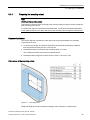
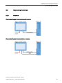
3.1.3
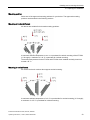
Checking clearances
The following clearances are required around the device to ensure adequate self-ventilation:
● At least 15 mm to the right and left of the mounting cutout (in x direction) to allow for
insertion of the mounting clips during installation
● At least 50 mm above and below the mounting cutout (in y direction) for ventilation
● At least 10 mm behind the rear panel of the device (in z direction)
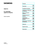
The figure below shows the clearances required with horizontal and vertical installation of the
device:
①
②
Clearance for horizontal installation (all devices)
x
At least 15 mm distance
y
At least 50 mm distance
z
At least 10 mm distance
Clearance for vertical installation (monitor and touch versions only)
Note
Ensure that the maximum ambient temperature is not exceeded when mounting the device
in a cabinet and especially in a closed enclosure.
Industrial Flat Panel IFP1500, IFP1900, IFP2200
24
Operating Instructions, 11/2014, A5E31298376-AC
Installing and connecting the device
3.1 Preparing for installation
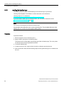
3.1.4
Preparing the mounting cutout
Note
Stability of the mounting cutout
The material in the area of the mounting cutout must be sturdy enough to ensure permanent
safe mounting of the device.
To achieve the degrees of protection described below, it must be ensured that deformation
of the material cannot occur due to the force of the mounting clips or operation of the device.
Degrees of protection
The various degrees of protection of the device can only be guaranteed if the following
requirements are met:
● To achieve the degree of protection specified in the technical specifications: Material
thickness at the mounting cut-out: 2 mm to 6 mm
● Permitted deviation from plane at the mounting cutout: ≤ 0.5 mm
This condition must also be met for the installed device.
● Permitted surface roughness in the area of the seal: ≤ 120 µm (Rz 120)
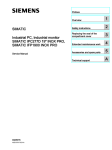
Dimensions of the mounting cutout
Figure 3-1
Mounting cutout
Width and height should be reversed accordingly when mounting in vertical format.
Industrial Flat Panel IFP1500, IFP1900, IFP2200
Operating Instructions, 11/2014, A5E31298376-AC
25
Installing and connecting the device
3.1 Preparing for installation
3.1.5
Labeling the function keys
Use labeling strips for project-related labeling of the function keys of your device.
Labeling strip templates are available in a Word document on the Internet at:
Labeling strips for 15" widescreen
(http://support.automation.siemens.com/DE/view/en/59000814)
If you would like to make your own labeling strips, you can find the dimensions under
"Dimensions for labeling strips (Page 71)".
Note
Do not write on the keyboard to label the function keys.
Any printable and writable film can be used as labeling strip. The permitted thickness of the
labeling strip is 0.15 mm. Do not use paper labeling strips.
Procedure
Proceed as follows:
1. Edit the template on a PC and then print it.
2. Apply a fixation spray film to the labeling strips.
The printout can be made water and smudge-proof with a fixation spray. The color printer
ink will not bleed onto the keyboard film as well.
3. Cut out the labeling strip.
4. Cut the corners at a 45° angle so that it is easier to slide the strip into the slot.
5. When the ink has dried, slide the labeling strips into the guide leaving a 3 cm clearance at
the end.
Industrial Flat Panel IFP1500, IFP1900, IFP2200
26
Operating Instructions, 11/2014, A5E31298376-AC
Installing and connecting the device
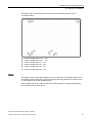
3.1 Preparing for installation
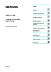
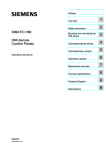
The figure below shows the positions of the guides for the labeling strips of the 15"
Touch/Key version.
①
②
③
④
⑤
⑥
Guide for labeling strips F1, F3 ... F15
Guide for labeling strips F2, F4 ... F16
Guide for labeling strips F17 ... F22
Guide for labeling strips F23 ... F26
Guide for labeling strips F27 ... F31
Guide for labeling strips F32 ... F36
Result
The labeling strips protrude approximately 3 cm out of the slot. The template dimensions for
the labeling strips are designed so that the labeling is correctly placed for the function keys.
It is not necessary to secure the labeling strip.
When installing the device, make sure that the labeling strips do not get jammed between
the mounting cutout and the device.
Industrial Flat Panel IFP1500, IFP1900, IFP2200
Operating Instructions, 11/2014, A5E31298376-AC
27
Installing and connecting the device
3.2 Mounting the device
3.2
Mounting the device
3.2.1
Notes on installation
Before installing the device, please ensure that the installation location complies with the
following:
WARNING
Risk of fire
The device is classified for use as "Open Type" according to UL508 in the Industrial Control
Equipment sector. In the event of overheating, the device may discharge burning materials
that can cause a fire.
Keep in mind:
• Requirement for approval and operation of the device according to UL508 is its
installation in a UL508-compliant enclosure.
• Install the device in an enclosure that meets the requirements of paragraphs 4.6 and
4.7.3 of the standards IEC/UL/EN/DIN-EN 60950-1.
● Ensure that the protective contact socket of the building installation is easily accessible
and that there is a mains disconnect switch in switchgear cabinet installations.
● Position the device so that it is not exposed to direct sunlight.
● Position the device so that it is easily accessible for the operator.
● Choose a suitable installation height.
● Ensure that the air vents of the device are not covered as a result of installation. Note the
permitted mounting positions.
Industrial Flat Panel IFP1500, IFP1900, IFP2200
28
Operating Instructions, 11/2014, A5E31298376-AC
Installing and connecting the device
3.2 Mounting the device
3.2.2
Mounting clips or mounting brackets, position for IP65
Types of mounting clips and mounting brackets
You can mount the device as follows:
● Device with 15", 19" or 22" display:
With 12 steel mounting clips (included in the scope of supply and available as
accessories, see section "Accessories")
● Device with 15", 19" or 22" display:
With 6 mounting brackets (available as accessories, see section "Accessories")
Industrial Flat Panel IFP1500, IFP1900, IFP2200
Operating Instructions, 11/2014, A5E31298376-AC
29
Installing and connecting the device
3.2 Mounting the device
Positions of the mounting clips or mounting brackets for IP65
To achieve the IP65 degree of protection for the device, the mounting clips or brackets must
be affixed at the positions shown below.
Device
Position
Touch screen device
with:
•
15" display
•
19" display
•
22" display
Touch/key device
with:
•
15" display
Industrial Flat Panel IFP1500, IFP1900, IFP2200
30
Operating Instructions, 11/2014, A5E31298376-AC
Installing and connecting the device
3.2 Mounting the device
3.2.3
Fastening the device with mounting clips or mounting brackets
Requirement
● All packaging components and protective films have been removed from the device.
● The mounting clips included in the accessory kit are to hand.
Procedure
Note
If the mounting seal is damaged, the degree of protection is not guaranteed.
Proceed as follows:
1. Working from the front, insert
the device into the mounting
cut-out. Secure the device to
prevent it from falling out.
2. Insert a mounting clip into the
cutout provided on the
device. Make sure it is in the
correct position; see the
section "Mounting clips or
mounting brackets, position
for IP65 (Page 29)".
3. Tighten the threaded pin to
secure the mounting clip. The
maximum torque when
tightening the threaded pins
of the mounting clips is 0.5
Nm.
4. Repeat steps 2 and 3 for all
mounting clips.
5. Check the fit of the mounting
seal.
Industrial Flat Panel IFP1500, IFP1900, IFP2200
Operating Instructions, 11/2014, A5E31298376-AC
31
Installing and connecting the device
3.2 Mounting the device
Mounting with optional mounting brackets
Mounting brackets can be used instead of mounting clips in steps 1 to 5:
3.2.4
Position of the mounting clips for IP66
Positions of the mounting clips
To achieve IP66 degree of protection instead of IP65 for a device with capacitive multi-touch
screen, fasten 4 additional mounting clips (available as accessories) at the positions marked
by the red boxes. The 15" display meets IP66 even without additional mounting clips.
Device
Position
Touch screen device
with:
•
19" display
•
22" display
Industrial Flat Panel IFP1500, IFP1900, IFP2200
32
Operating Instructions, 11/2014, A5E31298376-AC
Installing and connecting the device
3.3 Connecting the device
3.3
Connecting the device
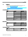
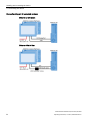
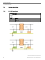
3.3.1
Overview
Connection diagram for standard monitor version
Connection diagram for standard touch version
Industrial Flat Panel IFP1500, IFP1900, IFP2200
Operating Instructions, 11/2014, A5E31298376-AC
33
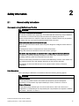
Installing and connecting the device
3.3 Connecting the device
Connection diagram for extended versions
Distance up to 5 meters
Distance of 5m to 30m
Industrial Flat Panel IFP1500, IFP1900, IFP2200
34
Operating Instructions, 11/2014, A5E31298376-AC
Installing and connecting the device
3.3 Connecting the device
3.3.2
Notes on connection
Requirement
● The device has been installed according to the information provided in these operating
instructions.
● Ensure only shielded data cables are used for operation, as described in the section
Accessories (Page 15).
Connection sequence
Connect the device in the following sequence:
1. PE conductor
2. Power supply
Perform a power-up test to ensure the power supply is connected with the correct
polarity.
3. PC
4. I/Os if needed
Note
Damage to the device
Failure to adhere to the connection sequence can damage the device.
Make sure you connect the device according to sequence listed above.
You disconnect the device in the reverse order.
Connecting the cables
When connecting the cables, make sure that you do not bend the contact pins.
Industrial Flat Panel IFP1500, IFP1900, IFP2200
Operating Instructions, 11/2014, A5E31298376-AC
35
Installing and connecting the device
3.3 Connecting the device
3.3.3
Connecting the protective earth
The relevant symbol on the device identifies the terminal for the earth connection.
Requirement
● T20 screwdriver
● Cable lug for M4
● PE conductor with a minimum cross-section of 2.5 mm2
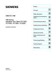
Procedure
1. Clamp the cable lug onto the
earth connection.
– PE conductor: yellow-green,
as depicted.
– Equipotential bonding: black
2. Using the M4 thread, firmly attach
the cable lug to the earth
connection on the device.
3. Connect the PE conductor or
equipotential bonding with the
earth connection of the cabinet or
plant in which the device is
installed.
Industrial Flat Panel IFP1500, IFP1900, IFP2200
36
Operating Instructions, 11/2014, A5E31298376-AC
Installing and connecting the device
3.3 Connecting the device
3.3.4
Connecting the power supply
Depending on the device version, you can operate the device with the following voltage:
● Standard monitor and standard touch versions: 24 V DC
● Extended versions: 24 V DC or 100 to 240 V AC
Note
To turn off the device completely, disconnect it from the power supply. The device does not
have an on/off switch.
3.3.4.1
Connecting the DC power supply
Note before connecting
NOTICE
Damage to device due to inadequate cable cross-section
Using power supply cables with cross-sections that are too small can damage the device in
the event of a short circuit. Only connect cables, therefore, with a minimum cross-section of
1.3 mm2 (16 AWG) and a maximum cross-section of 3.3 mm2 (12 AWG).
Note
The device may only be connected to a 24 V DC power supply that meets the requirements
of a safe extra-low voltage (SELV) according to IEC/EN/DIN EN/UL 60950-1.
The power supply must meet the requirements of NEC Class 2 or LPS according to
IEC/EN/DIN EN/UL 60950-1.
Since the ground/negative pole of the 24 V power supply and PE are connected to the
housing, the SELV power supply automatically becomes a PELV power supply. Bear this in
mind when connecting other devices.
Industrial Flat Panel IFP1500, IFP1900, IFP2200
Operating Instructions, 11/2014, A5E31298376-AC
37
Installing and connecting the device
3.3 Connecting the device
Procedure
1. Ensure that the cable ends of the
power supply lines are fitted with end
sleeves.
2. Fasten the end of a connecting cable
L+ and a connecting cable M with the
supplied power supply terminal.
3. Connect the power supply terminal to
the relevant terminal on the device.
4. Connect the remaining L+ and M ends
with the respective terminals on the
24 V DC power supply.
5. Switch on the 24 V DC power supply.
Industrial Flat Panel IFP1500, IFP1900, IFP2200
38
Operating Instructions, 11/2014, A5E31298376-AC
Installing and connecting the device
3.3 Connecting the device
3.3.4.2
Connecting an AC power supply
Note before connecting
NOTICE
Damage to the device in ungrounded supply systems
The device features a safety-certified power cable. Connect the device only to a grounding
socket. Operate the device only on grounded-neutral systems and not on impedancegrounded systems such as IT networks.
NOTICE
Damage to the device due to connection to the wrong supply voltage
If the local supply voltage is incompatible with the permissible rated voltage for the device,
damage to the equipment may result.
Always make sure that the local supply voltage complies with the permissible rated voltage
for the device.
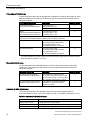
Regional information
Outside the United States and Canada, in regions with 230 V supply voltage:
If you do not use the safety-certified power cable, use a flexible, double-insulated power
supply cable (no single cables) with the following characteristics:
● At least 18 AWG (0.75 mm2) conductor cross-section
● Grounded safety plug 15 A, 250 V
Note
Ensure that the cable set conforms to the respective national safety regulations and is
appropriately labeled.
Industrial Flat Panel IFP1500, IFP1900, IFP2200
Operating Instructions, 11/2014, A5E31298376-AC
39
Installing and connecting the device
3.3 Connecting the device
For USA and Canada:
A CSA or UL-listed power supply cable must be used in the United States and Canada.
120 V power supply
Use a flexible cable with the following characteristics:
● UL approval
● CE marking
● Type SJT with three conductors
● At least 18 AWG (0.75 mm2) conductor cross-section
● Maximum 4.5 m length
● Parallel grounded safety plug 15 A, min. 125 V
230 V power supply
Use a flexible cable with the following characteristics:
● UL approval
● CE marking
● Type SJT with three conductors
● At least 18 AWG (0.75 mm2) conductor cross-section
● Maximum 4.5 m length
● Tandem grounded safety plug 15 A, min. 250 V
Procedure
Plug the connector of the supplied power
supply cable in the AC power supply
connector of the device.
Industrial Flat Panel IFP1500, IFP1900, IFP2200
40
Operating Instructions, 11/2014, A5E31298376-AC
Installing and connecting the device
3.3 Connecting the device
3.3.5
Connecting the device to a PC
3.3.5.1
Standard version
Procedure
1. Connect the Flat Panel and the PC using a DVI or DisplayPort
line.
2. If using a Touch version, also connect the device and the PC
with a USB line.
3.3.5.2
Procedure
Extended version
1. Connect the Flat Panel and the PC
using a DVI or DisplayPort line by
means of the respective interface.
2. If the distance between the Flat Panel
and the PC is less than 5 m, connect
the Flat Panel and PC using the USB
Type B interface.
3. If the distance between the Flat Panel
and the PC is less than 5 m, connect
the Flat Panel and PC with USB
transmitter module by means of the
USB-Link interface.
Note
Data transfer per USB transmitter module via USB1.1. The data transmission rate
corresponds to Full Speed according to USB1.1.
3.3.6
Connecting a USB device
Below are examples of devices you can connect to the USB interfaces of the device:
● External mouse
● External keyboard
● USB memory stick
Industrial Flat Panel IFP1500, IFP1900, IFP2200
Operating Instructions, 11/2014, A5E31298376-AC
41
Installing and connecting the device
3.3 Connecting the device
Note when connecting
Note
Use of USB devices
• The cable length of USB peripherals cannot exceed 3 m.
• Wait at least ten seconds between removal and reconnection of USB devices.
• When using standard USB peripherals, bear in mind that their EMC immunity level is
frequently designed for office applications only. These devices may be used for
commissioning and servicing. However, only industry-standard devices are allowed for
industrial operation.
• Peripherals are developed and marketed by individual vendors. The respective supplier
offers support for the I/O devices. Moreover, the terms of liability of the individual vendors
or suppliers apply here.
Note
Functional problem with USB port
If you connect an external device with a 230 V power supply to the USB port without using a
non-insulated installation, you may experience functional problems.
Use a non-insulated system design.
Excessive rated load on port
A USB device with too high a power load may possibly cause functional problems.
Observe the values for the maximum load of the USB interface. You will find the values in
the section "Technical specifications" (Page 73)".
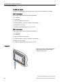
Front USB of the Touch/Key version
Note
Ensuring degree of protection IP65
When you loosen the sealing cover above the USB port to connect a USB component, the
degree of protection IP65 is no longer guaranteed for the device.
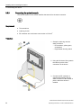
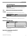
3.3.7
Securing the cables
Use cable ties to secure the connected cables to the selected fixing elements for strain relief.
Make sure that the cables are not crushed by the cable tie.
The figure below shows the fixing elements of the IFP1500 Touch.
Industrial Flat Panel IFP1500, IFP1900, IFP2200
42
Operating Instructions, 11/2014, A5E31298376-AC
Commissioning the device
4.1
4
General information on commissioning
If you want to operate the device exclusively as monitor, you do not need to commission the
device. To use the IPC Wizard functions (see section "Operating the device"), perform the
following commissioning steps.
Requirements
● The Industrial Flat Panel is connected to the power supply.
● The Industrial Flat Panel is connected to a SIMATIC IPC or PC with a DVI or DisplayPort
cable.
● The PC is equipped with a CD/DVD drive.
● The USB keyboard and USB mouse are connected to the PC.
● One of the supported operating systems is installed on the PC, see the section "SIMATIC
IPC Wizard / system requirements".
Procedure
1. Switch on the power supply of the Industrial Flat Panel.
2. Turn on the PC.
3. Follow the instructions in the section "Installing the SIMATIC IPC Wizard / IPC Wizard".
See also
Preface (Page 3)
Industrial Flat Panel IFP1500, IFP1900, IFP2200
Operating Instructions, 11/2014, A5E31298376-AC
43
Commissioning the device
4.2 Notes on various device configurations
4.2
Notes on various device configurations
4.2.1
SIMATIC IPC Wizard 2.1
SIMATIC IPC Wizard for SIMATIC Industrial PCs installs device-specific software and
drivers for operating your PC. These software components enable you to set the screen of
your SIMATIC device, for example, the brightness.
The SIMATIC IPC Wizard recognizes the existing hardware components and automatically
installs the associated software.
● SIMATIC Industrial PCs with preinstalled software contain the SIMATIC IPC Wizard that
runs automatically during initial commissioning.
● On SIMATIC Industrial PCs without preinstalled software, you can install the SIMATIC
IPC Wizard from the CD/DVD "Documentation and Drivers" on which the documentation
of the SIMATIC IPC Wizard is located.
4.2.1.1
System requirements
Hardware requirements
For the SIMATIC IPC Wizard you require the following hardware:
● PC with connected SIMATIC display: e.g. SIMATIC Panel PC or PC with connected
SIMATIC Industrial Flat Panel
● 650 MB of free hard disk space on the PC, C:\ partition
● The SIMATIC IPC display is fully connected:
– DVI / DP connection for video signals
– USB connection for touch signals
Note
Connected devices
The SIMATIC IPC Wizard does not support the combination of devices with resistive singletouch screen and capacitive multi-touch screen.
Note for SIMATIC Industrial Flat Panels:
• If you use a SIMATIC Industrial Flat Panel with the PC, connect the Industrial Flat Panel
to the PC before initial commissioning.
• During initial commissioning, multiple SIMATIC Industrial Flat Panels may be connected
to the PC.
Industrial Flat Panel IFP1500, IFP1900, IFP2200
44
Operating Instructions, 11/2014, A5E31298376-AC
Commissioning the device
4.2 Notes on various device configurations
Supported operating systems
The SIMATIC IPC Wizard on PCs runs with the following operating systems:
● Microsoft Windows 32-bit operating system
– Windows 7 Ultimate with SP1
– Windows Embedded Standard 7E 1 or 7P with SP1
● Microsoft Windows 64-bit operating system
– Windows 7 Ultimate with SP1
– Windows Server 2008 R2
– Windows Embedded Standard 7E 1 or 7P with SP1
For devices with capacitive multi-touch screen, WES7E is only supported in single-touch
mode (see manual "SIMATIC IPC Wizard 2.1", section "Toggling Switch Touch Mode").
1
Software requirements
● One of the operating systems named in "Supported operating systems" section is
installed.
● The driver of the device manufacturer for the graphics adapter is installed.
● The installed graphics driver supports reading of EDID data from the screen.
Note
The Microsoft VESA driver does not support all functions provided by the SIMATIC IPC
Wizard.
Setup cancels the installation.
4.2.1.2
Installing IPC Wizard
Requirement
● The system requirements are met.
● Do not apply with factory state: If following previous driver versions exist, uninstall them
via "Start > Control Panel > Programs and Features":
– IPC Wizard V1.0
– IPC Wizard V2.0
– IPC Switch Touch Mode V2.0.5
Industrial Flat Panel IFP1500, IFP1900, IFP2200
Operating Instructions, 11/2014, A5E31298376-AC
45
Commissioning the device
4.2 Notes on various device configurations
Procedure
1. Turn on the PC.
– With the factory state of some IPCs, the SIMATIC IPC Wizard is pre-installed. The
installation starts the first time the PC is switched on.
– If your SIMATIC IPC was delivered without pre-installed software, start the installation
of the SIMATIC IPC Wizard from the "Documentation and Drivers" CD/DVD. Select
the appropriate IPC Wizard for your device.
2. Follow the instructions.
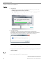
The SIMATIC IPC Wizard recognizes the existing hardware components and
automatically installs the associated software. This operation can take several minutes.
When all software components are installed, the following dialog is displayed:
Note
In the case of server operating systems the dialog contains the "Now" and "Later" buttons
instead of "OK".
3. Complete the installation with the "OK" button; for server operating systems use "Now".
The PC is restarted.
Result
You have installed the SIMATIC IPC Wizard software.
Industrial Flat Panel IFP1500, IFP1900, IFP2200
46
Operating Instructions, 11/2014, A5E31298376-AC
Operating the device
5.1
5
Operator input options
Depending on your device and the connected I/O devices, the following operator input
options are available:
● Integrated keyboard on touch device
● Touch screen for touch device
CAUTION
Unintentional actions with touch screen operation
If you touch the touch screen while system-internal processes are running, unintended
reactions of the device may be triggered.
Do not touch the screen in the following situations:
• During the boot process
• When plugging or unplugging USB components
• While Scandisk is running
• During a BIOS update
NOTICE
Damage to the touch screen
Hitting the touch screen with hard objects may damage it and can result in a total failure
of the touch screen.
Only touch the touch screen with your fingers or a suitable touch stylus.
● On-screen keyboard with touch device (see section "Using the on-screen keyboard")
● External keyboard, connected via USB
● External mouse, connected via USB
Industrial Flat Panel IFP1500, IFP1900, IFP2200
Operating Instructions, 11/2014, A5E31298376-AC
47
Operating the device
5.2 Operating a device with resistive single touch screen
5.2
Operating a device with resistive single touch screen
When you touch an object on the single touch screen, the corresponding function is
performed.
WARNING
Personal injury or property damage due to incorrect operation
Incorrect operation of devices with a touch screen can occur. This can result in personal
injury or property damage.
Take the following precautions:
• Configure the plant so that safety-related functions are not operated with the touch
screen.
• Always touch only a single point on the touch screen.
• Calibrate the touch screen, at the latest when the touch screen becomes inaccurate or
does not respond despite repeated touches.
• Switch off the device for cleaning and maintenance.
• Make sure that the touch screen is kept free of dirt.
NOTICE
Damage to the touch screen
Touching the touch screen with pointed or sharp objects can damage it and lead to a
significant reduction in service life or even total failure of the touch screen.
Do not touch the touch screen with pointed or hard objects. Only touch the touch screen
with your fingers, a touch stylus or an approved touch glove.
Note
Appearance of blisters under extreme ambient conditions
Under extreme environmental conditions such as high atmospheric humidity and
temperature, bubbles can form on the touch surface in rare cases. This only affects the
appearance and does not represent any functional restriction.
Industrial Flat Panel IFP1500, IFP1900, IFP2200
48
Operating Instructions, 11/2014, A5E31298376-AC
Operating the device
5.3 Operating a device with capacitive multi-touch screen
5.3
Operating a device with capacitive multi-touch screen
You operate the multi-touch screen with one or multiple fingers. You can also operate it
using gestures with up to five fingers at a time.
WARNING
Personal injury or property damage due to no earth connection
An inadequate earth connection or the lack of one may cause malfunction of the capacitive
touch screen. Functions may not work properly. This can result in personal injury or
property damage.
• Always connect the device to an earth conductor.
• The earth conductor from the device must be connected directly to earth with low
impedance (short connection, minimum cross-section 2.5 mm2).
You can find additional information on connecting the earth conductor in the section
"Connecting the protective earth (Page 36)".
WARNING
Personal injury or property damage due to maloperation
Incorrect operation of devices with a touch screen can occur. This can result in personal
injury or property damage.
Take the following precautions:
• Configure the plant so that safety-related functions are not operated with the touch
screen.
• Switch off the device for cleaning and maintenance.
WARNING
Danger of malfunction due to improper execution of gestures on the touch screen
If gestures are executed incorrectly on the touch screen with multi-touch function, these
gestures may not be recognized or could be recognized incorrectly. The entries made are
then not implemented by the device or are implemented incorrectly or in an unintended
manner.
Incorrect execution of multi-touch functions can lead to errors in the operation of the plant
and thus to physical injury.
Note the following when operating the touch screen with multi-touch function:
• The touch screen reacts to contact on its surface, not to pressure.
• When using a touch pen: Operate the touch screen only with a touch pen for capacitive
touch.
• Avoid unintended multiple touches, for example, with your knuckles.
Before you start to operate the device, make sure you are familiar with the multi-touch
functions of the Windows operating system, as well as with the application to be used and
its functions. Ensure that the gestures which the user executes on the multi-touch display
are recognized by the application. It is possible that certain gestures need to be trained
beforehand.
Industrial Flat Panel IFP1500, IFP1900, IFP2200
Operating Instructions, 11/2014, A5E31298376-AC
49
Operating the device
5.3 Operating a device with capacitive multi-touch screen
Notes on operation
Note when operating the multi-touch screen:
● Surface contact with a diameter of about 5 to 20 mm is required for an operator action to
be detected.
● An operation with gloves with a material thickness of <2 mm is detected in most cases.
However, check the usefulness of the gloves you are using.
● To avoid incorrect operation, certain inputs are ignored and blocked from further entry:
– Simultaneous operation with more than 5 fingers.
– Surface contact with a diameter of > 3 cm, for example, resting the palm of the hand
on the touch screen
– As soon as the touch screen is no longer touched, input is possible again.
Functions of the multi-touch screen
General functions
● Detection of up to 5 finger touches at a time.
● Detection of gestures that are supported by the operating system or the software installed
on the device.
Note
Multi-touch operation can provide advanced features or pose limitations depending on the
operating system and the software installed on the device. Read the corresponding
documentation.
● You do not need to calibrate the touch screen. Some operating systems do offer touch
calibration. However, this calibration does not lead to
improved accuracy.
Security functions in an industrial environment
The touch screen is locked for security reasons when following happens:
● There is a conductive liquid on the touch screen with ground contact via the enclosure or
the operator, for example.
● Electromagnetic interference is present that exceeds the specification according to EN
61000-4-2.
Once the interference is over, the touch screen is no longer locked.
Industrial Flat Panel IFP1500, IFP1900, IFP2200
50
Operating Instructions, 11/2014, A5E31298376-AC
Operating the device
5.4 Operating a Touch/Key device
5.4
Operating a Touch/Key device
Note
Maloperation
If you activate several keys simultaneously, a malfunction on the device cannot be excluded.
Only press the function keys one after the other.
Malfunctions of the user software
Always use security features of the KeyTools for security reasons. If you disable them,
nevertheless, serious malfunctions of the user software may occur when the additional
function keys F1 to F36 are used or if custom key code tables are used.
Risk of damage
Activating a key using a hard or pointed object, for example a screwdriver, reduces the life of
the key or can damage it.
External keyboard
Note
The keyboard layout has been set to "English/USA international". If you use a keyboard with
a layout other than the "English/USA international" layout, the key codes of the internal and
external keyboards might no longer correspond.
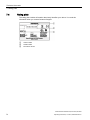
This section describes the keyboard assignment of the device in the delivery state.
The assignment of the keys, including the function keys and control of the LEDs, is specified
by means of the SIMATIC IPC KeyTools which is installed with the SIMATIC IPC Wizard.
You will find the SIMATIC IPC Wizard operating manual:
● On the "Documentation and Drivers" CD/DVD included in the delivery
● In the IPC Wizard installation folder on the PC after successful installation of the IPC
Wizard
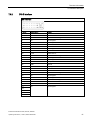
Alphanumeric keys
Key
Assignment lower case
LED "a/A" inactive
1
Assignment upper case
LED "a/A" active
<space>\@#%?!"':;<>()[]{}€$&%^°~|_1
Assignment SHIFT level
LED "a/A" active or inactive
<space>\@#%?!"':;<>()[]{}€$&%^°~|_!
2
abc2
ABC2
ABC@
3
def3
DEF3
DEF#
4
ghi4
GHI4
GHI$
5
jkl5
JKL5
JKL%
6
mno6
MNO6
MNO^
7
pqrs7
PRQRS7
PQRS&
8
tuv8
TUV8
TUV*
9
wxyz9
WXYZ9
WXYZ(
0
.,
+-*/=0
.,
.,
+_*?+)
><
Industrial Flat Panel IFP1500, IFP1900, IFP2200
Operating Instructions, 11/2014, A5E31298376-AC
51
Operating the device
5.4 Operating a Touch/Key device
The characters available for input depend on the text box involved. The figure below shows
the entry of an alphanumeric value using the system keys:
Control keys
The following table describes the control keys and their associated functions. With keyboard
shortcuts, hold the first key down. Then press the second button.
Key or keyboard
shortcut
Function
Switch between upper and lower case:
•
LED on: Upper case
•
LED off: Lower case
Deletes the character left of cursor.
Tabulator
Deletes the character to the right of the cursor or the highlighted text.
Toggles "overwrite" mode on or off.
If "overwrite" mode is switched on, the characters are overwritten to the right of
the cursor.
Open the TIA help, for example, from WinCC
The user software can specifically react to the stored key code. You can control the LED by means of the LEDControl program of the IPC Wizard.
Cancel
Press: Switches to an additional white key assignment.
Hold down: Switches between upper and lower case.
Acknowledge
The user software can specifically react to the stored key code. You can control the LED by means of the LEDControl program of the IPC Wizard.
General control function for use in keyboard shortcuts.
General control function for use in keyboard shortcuts.
Confirm input
Industrial Flat Panel IFP1500, IFP1900, IFP2200
52
Operating Instructions, 11/2014, A5E31298376-AC
Operating the device
5.5 IPC Wizard functions
Cursor keys
Key or keyboard
shortcut
Function
Moves the cursor, selection or a controller in the specified direction.
Moves the cursor or selection one page up.
Moves the cursor or selection one page down.
Moves the cursor to the start of the first screen.
Moves the cursor to the end of the last screen.
5.5
IPC Wizard functions
Software components
● General for all devices: Panel PC Tools
– SetBrightness
– IPCScreenSaver
● Special for devices with resistive single-touch screen: UPDD (Universal Pointing Device
Driver) with the following features
– Advanced touch features
– Calibrating
● Calibration is not necessary for devices with capacitive multi-touch screen. Depending on
your operating system, you may be able calibrate the touch screen through the operating
system, although it will not improve the accuracy.
All other functions are described in the manual "SIMATIC IPC Wizard 2.1 and Panel
Configuration Center":
● On the "Documentation and Drivers" CD/DVD included in the delivery
● In the IPC Wizard installation directory on the PC
Industrial Flat Panel IFP1500, IFP1900, IFP2200
Operating Instructions, 11/2014, A5E31298376-AC
53
Operating the device
5.5 IPC Wizard functions
Industrial Flat Panel IFP1500, IFP1900, IFP2200
54
Operating Instructions, 11/2014, A5E31298376-AC
Maintaining and servicing your device
6.1
6
Cleaning the device
Scope of maintenance
When working in areas where there is dust that may be hazardous to functionality, the
device must be operated in a control cabinet with a heat exchanger or with suitable supply
air.
Note
The dust deposits must be removed at appropriate time intervals.
Cleaning agents
Use dish soap or foaming screen cleaner only as cleaning agents.
NOTICE
Do not clean the device with aggresive solvents or scrubbing agents or with pressurized air
or steam cleaner.
Procedure
1. Switch off the device. This prevents the accidental triggering of functions when the screen
is touched.
2. Dampen the cleaning cloth.
3. Spray the cleaning agent on the cloth and not directly on the device.
4. Clean the device with the cleaning cloth.
Industrial Flat Panel IFP1500, IFP1900, IFP2200
Operating Instructions, 11/2014, A5E31298376-AC
55
Maintaining and servicing your device
6.2 Spare parts and repairs
6.2
Spare parts and repairs
WARNING
Risk of bodily injury or equipment damage due to unauthorized opening or repairing
Bodily injury or considerable equipment damage may result from the unauthorized opening
or repairing of the device. Do not carry out any repairs on your own. Repairs may only be
carried out by authorized qualified personnel at the manufacturer's site.
For repairs, send the device to the Return Center in Fürth. Repairs may only be carried out
at the Return Center in Fürth.
Depending on the work necessary to repair the device, the Center may decide to give you a
credit note. In this case, it is your responsibility to order a new device.
The address is:
Siemens AG
Industry Sector
Returns Center
Siemensstr. 2
90766 Fürth Germany
See also
Spare parts and repairs (http://support.automation.siemens.com/WW/view/en/16611927)
6.3
Recycling and disposal
The devices described in these operating instructions can be recycled thanks to their low
level of pollutants. Contact a certified disposal service company for environmentally sound
recycling and disposal of your old devices.
Industrial Flat Panel IFP1500, IFP1900, IFP2200
56
Operating Instructions, 11/2014, A5E31298376-AC
Technical information
7.1
7
Certificates and approvals
Note
Approvals on the rating plate
The following overview provides information on possible approvals.
Only the approvals on the rating plate (Page 72) of the specific device apply.
CE marking
The devices meet the general and safety-related requirements of the following EC directives
and conform to the harmonized European standards (EN) for these devices published in the
official gazettes of the European Community:
● 2006/95/EC "Electrical equipment for use within specific voltage limits" (Low-Voltage
Directive)
● 2004/108/EC "Electromagnetic Compatibility" (EMC Directive)
● 94/9/EC "Devices and protection systems for use as prescribed in
potentially explosive areas" (Guidelines for Explosion Protection)
EC Declaration of Conformity
The EC Declarations of Conformity are available to the relevant authorities at the following
address:
Siemens Aktiengesellschaft
Industry Sector
I IA AS FA WF AMB
PO Box 1963
D-92209 Amberg, Germany
You can download information on the EC Declaration of Conformity, here under the keyword
"Declaration of Conformity":
Certificate Industrial Flat Panel
(http://support.automation.siemens.com/WW/view/en/60242448/134200).
Software license agreements
If the device is supplied with preinstalled software, you must observe the corresponding
license agreements.
Industrial Flat Panel IFP1500, IFP1900, IFP2200
Operating Instructions, 11/2014, A5E31298376-AC
57
Technical information
7.1 Certificates and approvals
UL approval
Underwriters Laboratories Inc., to
● UL 508 (Industrial Control Equipment)
● CSA C22.2 No. 142 (Process Control Equipment)
or
Underwriters Laboratories Inc., to
● UL 508 (Industrial Control Equipment)
● CSA C22.2 No. 142 (Process Control Equipment)
● ANSI/ISA 12.12.01 (Hazardous Location)
● CSA-213 (Hazardous Location)
Approved for use in
● Class I, Division 2, Group A, B, C, D or
● Class I, Zone 2, Group IIC or
● non-hazardous locations
FM Approval
Factory Mutual Research (FM) conforming to
● Approval Standard Class Number 3611, 3600, 3810, ANSI/ISA 61010-1
● CSA C22.2 No. 213
● CSA C22.2 No. 1010.1
Approved for use in
● Class I, Division 2, Group A, B, C, D T4
● Class I, Zone 2, Group IIC T4
Ex approval
The following approvals apply to the device in accordance with
● IEC 60079-0:2011 and EN 60079-0:2012
● IEC 60079-15:2010 and EN 60079-15:2010
● IEC 60079-31: 2008 and EN 60079-31:2009
valid:
II 3 G
Ex nA IIC Tx Gc
II 3 D
Ex tc IIIC T 70 °C Dc IP65
x: Temperature values, see EC design examination certificate
The EC type examination certificates are available on the Internet at:
Technical Support (http://www.siemens.de/automation/csi_en_WW)
Industrial Flat Panel IFP1500, IFP1900, IFP2200
58
Operating Instructions, 11/2014, A5E31298376-AC
Technical information
7.1 Certificates and approvals
The table below describes the test numbers of the HMI device classes:
Manufacturer site
HMI device class
Test number
Siemens AG
Comfort Panel, ITC, IFP
DEKRA11ATEX0005X
Industry Sector
IECEx DEK 13.0085X
Werner-von-Siemens-Straße 50
D-92209 Amberg, Germany
FCC and Canada
USA
Federal CommuThis equipment has been tested and found to comply with the limits for a Class
nications Commis- A digital device, pursuant to Part 15 of the FCC Rules. These limits are designed
sion
to provide reasonable protection against harmful interference when the equipment is operated in a commercial environment. This equipment generates, uses,
Radio Frequency
and can radiate radio frequency energy and, if not installed and used in accordInterference
ance with the instruction manual, may cause harmful interference to radio comStatement
munications. Operation of this equipment in a residential area is likely to cause
harmful interference in which case the user will be required to correct the interference at his own expense.
Shielded Cables
Shielded cables must be used with this equipment to maintain compliance with
FCC regulations.
Modifications
Changes or modifications not expressly approved by the manufacturer could
void the user's authority to operate the equipment.
Conditions of
Operations
This device complies with Part 15 of the FCC Rules. Operation is subject to the
following two conditions: (1) this device may not cause harmful interference, and
(2) this device must accept any interference received, including interference that
may cause undesired operation.
CANADA
Canadian Notice
This Class A digital apparatus complies with Canadian ICES-003 (B).
Avis Canadien
Cet appareil numérique de la classe A est conforme à la norme NMB003 (B) du Canada.
AUSTRALIA / NEW ZEALAND
This product meets the requirements of EN 61000-6-4:2007 Generic standards - Emission
standard for industrial environments.
This product meets the requirements of the standard EN 61000-6-4:2007 Generic standards
– Emission standard for industrial environments.
KOREA
This product meets the requirements of Korean certification.
This product satisfies the requirement of the Korean Certification (KC Mark).
이 기기는 업무용(A급) 전자파 적합기기로서 판매자 또는 사용자는 이 점을 주의하시기
바라며 가정 외의 지역에서 사용하는 것을 목적으로 합니다.
Industrial Flat Panel IFP1500, IFP1900, IFP2200
Operating Instructions, 11/2014, A5E31298376-AC
59
Technical information
7.2 Directives and declarations
Marine approvals
Acceptance procedures for shipping and offshore applications in preparation:
● ABS American Bureau of Shipping (USA)
● BV Bureau Vertias (France)
● DNV Det Norske Veritas (Norway)
● GL Germanische Lloyd
● LR Lloyds Register of Shipping
● Class NK Nippon Kaiji Kyokai (Japan)
7.1.1
Programmable logic controllers
IEC 61131 programmable logic controllers
The devices meet the requirements and criteria of the IEC 61131-2 standard: Programmable
Logic Controllers – Part 2: Operating resource requirements and tests.
7.2
Directives and declarations
7.2.1
ESD guideline
What does ESD mean?
An electronic module is equipped with highly integrated components. Due to their design,
electronic components are highly sensitive to overvoltage and thus to the discharge of static
electricity. Such electronic components or modules are labeled as electrostatic sensitive
devices.
The following abbreviations are commonly used for electrostatic sensitive devices:
● ESD – Electrostatic sensitive device
● ESD – Electrostatic Sensitive Device as a common international designation
Electrostatic sensitive devices can be labeled with an appropriate symbol.
Industrial Flat Panel IFP1500, IFP1900, IFP2200
60
Operating Instructions, 11/2014, A5E31298376-AC
Technical information
7.2 Directives and declarations
NOTICE
Damage to ESD from touch
Electrostatic sensitive devices, ESD, can be destroyed by voltages which are far below the
human perception limit. If you touch a component or electrical connections of a module
without discharging any electrostatic energy, these voltages may arise.
The damage to a module by an overvoltage can often not be immediately detected and only
becomes evident after an extended period of operation. The consequences are incalculable
and range from unforeseeable malfunctions to a total failure of the machine or system.
Avoid touching components directly. Make sure that persons, the workstation and the
packaging are properly grounded.
Charge
Every person without a conductive connection to the electrical potential of his/her
surroundings can be electrostatically charged.
The material with which this person comes into contact is of particular significance. The
figure shows the maximum electrostatic voltages with which a person is charged, depending
on humidity and material. These values conform to the specifications of IEC 61000-4-2.
①
②
③
Synthetic materials
Wool
Antistatic materials such as wood or concrete
Industrial Flat Panel IFP1500, IFP1900, IFP2200
Operating Instructions, 11/2014, A5E31298376-AC
61
Technical information
7.2 Directives and declarations
NOTICE
Grounding measures
There is no equipotential bonding without grounding. An electrostatic charge is not
discharged and may damage the ESD.
Protect yourself against discharge of static electricity. When working with electrostatic
sensitive devices, make sure that the person and the workplace are properly grounded.
Protective measures against discharge of static electricity
● Disconnect the power supply before you install or remove modules which are sensitive to
ESD.
● Pay attention to good grounding:
– When handling electrostatical sensitive devices, make sure that persons, the
workstation and devices, tools and packaging used are properly grounded. This way
you avoid static discharge.
● Avoid direct contact:
– As a general rule, do not touch electrostatic sensitive devices, except in the case of
unavoidable maintenance work.
– Hold the modules at their edge so that you do not touch the connector pins or
conductor paths. This way, the discharge energy does not reach and damage the
sensitive components.
– Discharge your body electrostatically before you take a measurement at a module. Do
so by touching grounded metallic parts. Always use grounded measuring instruments.
7.2.2
Electromagnetic compatibility
Pulse-shaped interference
The Industrial Flat Panels have been tested for high-energy single pulse (surge) in
accordance with IEC 61000-4-5.
An external protective circuit is required for operation with 24 VDC; please refer to the
chapter "Lightning and Surge Voltage Protection" in the "S7-300 Automation System,
Hardware and Installation" installation manual. The "S7-300 Automation System, Hardware
and Installation" installation manual is available for download from the Internet
(http://support.automation.siemens.com/WW/view/en/15390415).
The following lightning protection element was used during the testing of the Industrial Flat
Panel:
Dehn BVT AVD 24" (Order No. 918 422)
Industrial Flat Panel IFP1500, IFP1900, IFP2200
62
Operating Instructions, 11/2014, A5E31298376-AC
Technical information
7.3 Dimension drawings
7.3
Dimension drawings
7.3.1
Dimension drawing of the IFP1500 Multitouch
Industrial Flat Panel IFP1500, IFP1900, IFP2200
Operating Instructions, 11/2014, A5E31298376-AC
63
Technical information
7.3 Dimension drawings
7.3.2
Dimension drawing of the IFP1500 Monitor and Touch
Industrial Flat Panel IFP1500, IFP1900, IFP2200
64
Operating Instructions, 11/2014, A5E31298376-AC
Technical information
7.3 Dimension drawings
7.3.3
Dimension drawing of the IFP1900 Multitouch
Industrial Flat Panel IFP1500, IFP1900, IFP2200
Operating Instructions, 11/2014, A5E31298376-AC
65
Technical information
7.3 Dimension drawings
7.3.4
Dimension drawing of the IFP1900 Monitor and Touch
Industrial Flat Panel IFP1500, IFP1900, IFP2200
66
Operating Instructions, 11/2014, A5E31298376-AC
Technical information
7.3 Dimension drawings
7.3.5
Dimension drawing of the IFP2200 Multitouch
Industrial Flat Panel IFP1500, IFP1900, IFP2200
Operating Instructions, 11/2014, A5E31298376-AC
67
Technical information
7.3 Dimension drawings
7.3.6
Dimension drawing of the IFP2200 Monitor and Touch
Industrial Flat Panel IFP1500, IFP1900, IFP2200
68
Operating Instructions, 11/2014, A5E31298376-AC
Technical information
7.3 Dimension drawings
7.3.7
Dimension drawing of the IFP1500 Touch/Key
Industrial Flat Panel IFP1500, IFP1900, IFP2200
Operating Instructions, 11/2014, A5E31298376-AC
69
Technical information
7.3 Dimension drawings
7.3.8
Dimension drawing Host Unit USB
The Host Unit USB is available as an accessory (DVI/USB cable sets >5 m).
Industrial Flat Panel IFP1500, IFP1900, IFP2200
70
Operating Instructions, 11/2014, A5E31298376-AC
Technical information
7.3 Dimension drawings
7.3.9
Dimensions for labeling strips
This section contains the dimensions of the labeling strips for 15" widescreen devices.
Labeling strip templates are available in a Word document on the Internet at:
Labeling strips for 15" widescreen
(http://support.automation.siemens.com/DE/view/en/59000814)
Industrial Flat Panel IFP1500, IFP1900, IFP2200
Operating Instructions, 11/2014, A5E31298376-AC
71
Technical information
7.4 Rating plate
7.4
Rating plate
The rating plate includes information that clearly identifies your device. You need this
information when you contact Customer Support.
①
②
③
Order number
Serial number
Production version
Industrial Flat Panel IFP1500, IFP1900, IFP2200
72
Operating Instructions, 11/2014, A5E31298376-AC
Technical information
7.5 Technical specifications
7.5
Technical specifications
7.5.1
General technical specifications
Weight
Weight without
packaging
IFP1500 1
IFP1500 2
IFP1900
3.9 kg
4.2 kg
5.5 kg
IFP1900
Multitouch
IFP2200
5.8 kg
6.5 kg
IFP2200
Multitouch
IFP1500
Touch/Key
6.7 kg
4.3 kg
Display
IFP1500 1
IFP1500 2
Type
Active display area
Resolution
15.4''
15.6''
18.5''
21.5''
331.2 × 207 mm
344.2 × 193.5 mm
409.8 × 230.4 mm
475.2 × 267.3 mm
1280 x 800 pixels
1366 x 768 pixels
1366 x 768 pixels
1920 x 1080 pixels
Up to 16 million
Brightness control
Half Brightness Life
Time (MTBF 3)
By means of SetBrightness tool, value range 10% to 100%
LED
LED
LED
LED
80000 h
70000 h
50000 h
30000 h
Pixel error class in
accordance with
ISO 9241-307
1
2
3
IFP2200
LCD widescreen TFT
Possible colors
Backlighting
IFP1900
I
resistive touch screen only
capacitive touch screen only
MTBF: Operating hours after which the maximum screen brightness is reduced by half compared to the original value.
MTBF is increased by using the integrated dimming function, for example time-controlled via screen saver or centrally
via PROFIenergy.
Industrial Flat Panel IFP1500, IFP1900, IFP2200
Operating Instructions, 11/2014, A5E31298376-AC
73
Technical information
7.5 Technical specifications
Input device
Monitor
standard versions
Touch
standard versions
No
On-screen keyboard
Keyboard
Analog resistive
single touch screen
No
Capacitive multitouch screen
No
Touch
Extended versions
IFP1500 Touch/Key
•
On-screen keyboard
•
On-screen keyboard
•
Externally via USB
•
Externally via USB
•
Device keys
Yes
Yes 1
No
Function keys
No
36
Labeling strips
No
Yes
not with 15" devices
1
Interfaces
Monitor
standard versions
Touch
standard versions
DVI-D
Touch
Extended versions
IFP1500 Touch/Key
2
1
Yes
DisplayPort
Yes
USB Type A, rear 1
USB Type A, front
No
No
1
USB Type B, host
1
No
USB Link, RJ45
1
No
1
USB type A, maximum load 500 mA, equivalent to USB standard 2.0
1
DC power supply
IFP1500
IFP1900
Rated voltage
Permitted voltage range
Rated current
Inrush current
IFP2200
24 V DC
+19.2 V to +28.8 V
2.0 A
I2t
Power consumption, typical
Maximum permitted transients
Minimum time between two transients
Internal protection
2.5 A
0.5
A2s
40 W
35 V (500 ms)
50 s
Electronic
Industrial Flat Panel IFP1500, IFP1900, IFP2200
74
Operating Instructions, 11/2014, A5E31298376-AC
Technical information
7.5 Technical specifications
AC power supply
Extended versions
Rated voltage
230 V AC
Permitted voltage range
100 ... 240 V
Rated current
Inrush current
200 mA
I2t
0.5 A2s
Power consumption, typical
40 W
Minimum time between two transients
50 s
Internal protection
Electronic
7.5.2
Ambient conditions
7.5.2.1
Transport and storage conditions
Mechanical and climatic conditions for transportation and storage
The requirements regarding transport and storage conditions for the device are more
stringent than those laid down in IEC 60721-3-3. The following requirements apply to the
transport and storage of the device in its original packaging.
The climatic conditions conform to:
● Class 3M3 (mechanical requirements)
● Class 3K3 (climatic requirements)
Type of condition
Permitted range
Drop test (in transport package)
≤1m
Temperature
From –20 to +60° C
Atmospheric pressure
From 1080 to 660 hPa,
Corresponds to an elevation of –1 000 to 3 500 m
Relative humidity
From 10 to 90%, without condensation
Sinusoidal vibration in accordance with
IEC 60068-2-6
5 to 8.4 Hz: 3.5 mm
Shock in accordance with IEC 60068-2-27
25 g, 6 ms, 1 000 shocks
8.4 to 500 Hz: 9.8 m/s2
Proper transport and storage, installation and assembly as well as careful operation and
maintenance are prerequisites for trouble-free and safe operation of the device.
Non-compliance will render the warranty for the device null and void.
Industrial Flat Panel IFP1500, IFP1900, IFP2200
Operating Instructions, 11/2014, A5E31298376-AC
75
Technical information
7.5 Technical specifications
7.5.2.2
Operating conditions
Mechanical and climatic conditions of use
The device is designed for use in locations protected from the effects of the weather. The
conditions of use meet the requirements for DIN IEC 60721-3-3:
● Class 3M3 (mechanical requirements)
● Class 3K3 (climatic requirements)
Use with additional measures
The device should not be used at the following locations unless additional measures are
taken:
● In locations with a high degree of ionizing radiation
● In locations with severe operating conditions, for example, due to:
– Corrosive vapors, gases, oils or chemicals
– Electrical or magnetic fields of high intensity
● In systems that require special monitoring - for example:
– Elevators
– Systems in especially hazardous rooms
Mechanical ambient conditions
The mechanical ambient conditions for the device are specified in the table below in terms of
sinusoidal vibration.
Frequency range f in Hz
Constant
Occasional
5 Hz ≤ f ≤ 8.4 Hz
Amplitude 0.0375 mm
Amplitude 3.5 mm
8.4 Hz ≤ f ≤ 150 Hz
Constant acceleration 0.5 g
Constant acceleration 1 g
Reducing vibrations
If the device is subjected to greater shocks or vibrations, you must take appropriate
measures to reduce acceleration or amplitudes.
We recommend mounting the device on damping materials, such as rubber-metal vibration
dampers.
Industrial Flat Panel IFP1500, IFP1900, IFP2200
76
Operating Instructions, 11/2014, A5E31298376-AC
Technical information
7.5 Technical specifications
Testing mechanical ambient conditions
The table below provides information on the type and scope of tests for mechanical ambient
conditions.
Tested for
Test standard
Comments
Vibrations
Vibration test in accordance
with IEC 60068, part 2–6
(sinusoidal)
Type of vibration:
Frequency cycles at a rate of change of 1 octave/minute.
5 Hz ≤ f ≤ 8.4 Hz, constant amplitude 3.5 mm
8.4 Hz ≤ f ≤ 150 Hz, constant acceleration 1 g
Vibration duration:
10 frequency cycles per axis in each of the three
mutually vertical axes
Shock
Shock test in accordance
with IEC 60068, Part 2 –27
Type of shock: Half-sine
Severity of shock:
Peak value 15 g, duration 11 ms
Direction of shock:
3 shocks in ± direction of axis in each of the
three axes vertical to each other
Climatic ambient conditions
The following table shows the climatic ambient conditions for operation of the device.
Ambient conditions
Permitted range
Comments
Temperature:
Vertical mounting
From 0 to 50 °C (horizontal) 1
From 0 to 40 °C (vertical)
Mounting at an angle
From 0 to 40 °C (horizontal)
Slope angle max. 35°
From 0 to 35 °C (vertical)
Relative humidity
10 to 90%, without condensation
Atmospheric pressure
1 080 to 795 hPa
Corresponds to an elevation
of -1000 m to 2000 m
Pollutant concentration
SO2: < 0.5 vpm;
Test: 10 cm3/m3; 10 days
Relative humidity <60%, no condensation
H2S: < 0.1 vpm;
Test: 1 cm3/m3; 10 days
Relative humidity <60%, no condensation
1
IFP1900 and IFP2200: From 0 to 45° C
Industrial Flat Panel IFP1500, IFP1900, IFP2200
Operating Instructions, 11/2014, A5E31298376-AC
77
Technical information
7.5 Technical specifications
Pulse-shaped interference
The following table shows the electromagnetic compatibility of modules with regard to pulseshaped interference. This requires the device to meet the specifications and directives for
electrical installation.
Pulse-shaped interference
Test voltage
Electrostatic discharge
in accordance with IEC 61000-4-2
Air discharge: 8 kV
Contact discharge: 6 kV
3
Contact discharge: 4 kV
2
2 kV power supply cable
2 kV signal cable, > 30 m
1 kV signal cable, < 30 m
3
Bursts
(high-speed transient interference)
in accordance with IEC 61000-4-4
Degree of severity
High-power surge pulses in accordance with IEC 61000-4-5, external protective circuit required (refer
to S7-300 PLC, Installation, chapter “Lightning and overvoltage protection”).
Asymmetrical coupling
2 kV power supply cable
DC voltage with protective elements 1
3
2 kV signal/data cable, > 30 m,
with protective elements as required 1
Symmetrical coupling
1 kV power supply cable
DC voltage with protective elements 1
3
1 kV signal cable, > 30 m,
with protective elements as required 1
1
The following lightning protection element was used during the testing of the Industrial Flat Panel:
Dehn BVT AVD 24" (Order No. 918 422)
Sinusoidal interference
The following table shows the EMC behavior of the modules with respect to sinusoidal
interference. This requires the HMI device to meet the specifications and directives for
electrical installation.
Sinusoidal interference
Test values
Degree of severity
HF radiation (electromagnetic
fields) according to IEC 61000-4-3
80% amplitude modulation at 1 kHz
with 10 V/m in range of 80 MHz to 1 GHz
with 3 V/m in the range 1.4 GHz to 2 GHz
with 1 V/m the range 2 GHz to 2.7 GHz
3
HF power applied to lines and line
shields according IEC 61000-4-6
Test voltage 10 V, with 80% amplitude
modulation of 1 KHz in the range of
150 KHz to 80 MHz
3
Emission of radio interference
The following table shows the unwanted emissions from electromagnetic fields in
accordance with EN 55016, Limit Value Class A, Group 1, measured at a distance of 10 m.
Radiated emission (emitted interference)
From 1 GHz to 3 GHz
< 66 dB peak and < 46 dB average
From 3 GHz to 6 GHz
< 70 dB peak and < 50 dB average
From 30 to 230 MHz
< 40 dB (μV/m) quasi-peak
From 230 to 1000 MHz
< 47 dB (μV/m) quasi-peak
Industrial Flat Panel IFP1500, IFP1900, IFP2200
78
Operating Instructions, 11/2014, A5E31298376-AC
Technical information
7.5 Technical specifications
Emission of radio interference voltages
From 0.150 MHz to 0.5 MHz
< 79 dB quasi-peak and < 66 dB average
From 0.5 MHz to 30 MHz
< 73 dB quasi-peak and < 60 dB average
Additional measures
Before you connect a device to the public network, ensure that it is compliant with Limit
Class B in accordance with EN 55022.
7.5.2.3
Information on insulation tests, protection class and degree of protection
Test voltages
Insulation strength is demonstrated in the type test with the following test voltages in
accordance with IEC 61131-2:
Circuits with a nominal voltage of Ue to
other circuits or ground
Test voltage
24 V
707 V DC or 500 V AC
Protection class
Protection Class I in accordance with IEC 61140, i.e. PE/ground terminal to profile rail
required.
Protection against foreign objects and water
Degree of protection in accordance with
IEC 60529
Explanation
Front
When mounted:
Rear panel
•
IP65
•
Front face only Type 4X/Type 12 (indoor use only)
IP20
Touch protection test with standard test probes.
There is no protection against ingress by water.
The degree of protection of the front panel can only be guaranteed if the mounting seal is
properly installed at the mounting cut-out and the cover flap of the USB interface is closed on
the Touch/Key device.
Degree of pollution / overvoltage category according to IEC 61131
● Degree of pollution 2
● Overvoltage category II
Industrial Flat Panel IFP1500, IFP1900, IFP2200
Operating Instructions, 11/2014, A5E31298376-AC
79
Technical information
7.6 Interface description
7.6
Interface description
7.6.1
24 V DC Power Supply
24 V DC power supply
1
Pin no.
Meaning
1
+24 V DC
2
GND 1 24 V
GND is internally connected to signal ground on DVI, for example, device ground and housing:
Industrial Flat Panel IFP1500, IFP1900, IFP2200
80
Operating Instructions, 11/2014, A5E31298376-AC
Technical information
7.6 Interface description
7.6.2
DVI-D interface
DVI-D interface
Pin no.
Abbreviation
Signal
1
TX2N
TDMS data 2-
2
TX2P
TDMS data 2+
3
GND
TMDS data shield 2, ground
4
NC
Not assigned
5
NC
Not assigned
6
DDC CLK
DDC clock
7
DDC CLK
DDC data
8
NC
Not assigned
9
TX1N
TDMS data 1-
10
TX1P
TDMS data 1+
11
GND
TMDS data shield 1, ground
12
NC
Not assigned
13
NC
Not assigned
14
+5 V
+5 V power
15
GND
Ground
16
MONDET
Hotplug detect
17
TX0N
TDMS data 0-
18
TX0P
TDMS data 0+
19
GND
TMDS data shield 0, ground
20
NC
Not assigned
21
NC
Not assigned
22
GND
TMDS clock shield, ground
23
TXCP
TDMS clock +
24
TXCN
TDMS clock -
C1
NC
Not assigned
C2
C3
C4
C5
Industrial Flat Panel IFP1500, IFP1900, IFP2200
Operating Instructions, 11/2014, A5E31298376-AC
81
Technical information
7.6 Interface description
7.6.3
DisplayPort
DisplayPort interface
Pin no.
Abbreviation
Meaning
Input/output
1
ML_Lane3-
DP data 3-
Input
2
GND
Ground
-
3
ML_Lane3+
DP data 3+
Input
4
ML_Lane2-
DP data 2-
Input
5
GND
Ground
-
6
ML_Lane2+
DP data 2+
Input
7
ML_Lane1-
DP data 1-
Input
8
GND
Ground
-
9
ML_Lane1+
DP data 1+
Input
10
ML_Lane0-
DP data 0-
Input
11
GND
Ground
-
12
ML_Lane0+
DP data 0+
Input
13
CONFIG1 CAD
Cable Adapter Detect
Input
14
CONFIG2
Ground (PullDown)
-
15
AUX_CH+
Auxiliary channel+
Bidirectional
16
GND
Ground
-
17
AUX_CH-
Auxiliary channel-
Bidirectional
18
HPD
Hot Plug Detect
Input
19
GND
Ground
-
20
DP_PWR
+3.3 V (fused)
Input
Industrial Flat Panel IFP1500, IFP1900, IFP2200
82
Operating Instructions, 11/2014, A5E31298376-AC
Technical information
7.6 Interface description
7.6.4
USB interface, Type B
USB interface, Type B
7.6.5
Pin No.
Abbreviation
Signal
1
VCC
+ 5 V (fused)
2
- Data
Data channel
3
+ Data
Data channel
4
GND
Ground
USB hub, Type A
USB port
Pin No.
Short name
Signal
1
VCC
+ 5 V (fused)
2
- Data
Data channel
3
+ Data
Data channel
4
GND
Ground
Industrial Flat Panel IFP1500, IFP1900, IFP2200
Operating Instructions, 11/2014, A5E31298376-AC
83
Technical information
7.6 Interface description
Industrial Flat Panel IFP1500, IFP1900, IFP2200
84
Operating Instructions, 11/2014, A5E31298376-AC
Technical Support
A.1
A
Service and support
You can find additional information and support for the products described on the Internet at
the following addresses:
● Technical support (http://www.siemens.de/automation/csi_en_WW)
● Support request form (http://www.siemens.com/automation/support-request)
● After Sales Information System SIMATIC IPC/PG (http://www.siemens.com/asis)
● SIMATIC Documentation Collection (http://www.siemens.com/simatic-tech-doku-portal)
● Your local representative
(http://www.automation.siemens.com/mcms/aspa-db/en/Pages/default.aspx)
● Training center (http://sitrain.automation.siemens.com/sitrainworld/?AppLang=en)
● Industry Mall (https://mall.industry.siemens.com)
When contacting your local representative or Technical Support, please have the following
information at hand:
● MLFB of the device
● BIOS version for industrial PC or image version of the device
● Other installed hardware
● Other installed software
Tools & downloads
Please check regularly if updates and hotfixes are available for download to your device. The
download area is available on the Internet at the following link:
After Sales Information System SIMATIC IPC/PG (http://www.siemens.com/asis)
See also
Rating plate (Page 72)
Industrial Flat Panel IFP1500, IFP1900, IFP2200
Operating Instructions, 11/2014, A5E31298376-AC
85
Technical Support
A.1 Service and support
Industrial Flat Panel IFP1500, IFP1900, IFP2200
86
Operating Instructions, 11/2014, A5E31298376-AC
B
List of abbreviations
ANSI
American National Standards Institute
ASCII
American Standard Code for Information Interchange
B
Width
BLI
Backlight Inverter
BIOS
Basic Input Output System
CD-ROM
Compact Disc – Read Only Memory
CPU
Central Processing Unit
DC
Direct Current
DHCP
Dynamic Host Configuration Protocol
DNS
Domain Name Service
DP
Distributed I/O
DSN
Data Source Name
DVD-ROM
Digital Versatile Disc – Read Only Memory
ESD
Electrostatic Sensitive Devices
EMC
ElectroMagnetic Compatibility
H
Height
HF
High Frequency
HMI
Human Machine Interface
IF
Interface: Interface
LCD
Liquid Crystal Display: Liquid crystal display
LED
Light Emitting Diode: Light emitting diode
LPS
Limited Power Source
Mbps
Megabits per second
OSD
OnScreenDisplay
OSK
OnScreenKeyboard
PC
Personal Computer
PG
Programming device
PPI
Point to Point Interface SIMATIC S7
PS/2
Personal System 2
RoHS
Restriction of the use of certain hazardous substances in electrical and electronic equipment
PLC
Programmable logic controller
T
Device depth
TCP/IP
Transmission Control Protocol/Internet Protocol
USB
Universal Serial Bus
VGA
Video Graphics Array
Industrial Flat Panel IFP1500, IFP1900, IFP2200
Operating Instructions, 11/2014, A5E31298376-AC
87
List of abbreviations
Industrial Flat Panel IFP1500, IFP1900, IFP2200
88
Operating Instructions, 11/2014, A5E31298376-AC
Glossary
Application
An application is a program which is put directly on the operating system MS-DOS or
windows. An application on the PC/PG, for example, is STEP 7.
Controller
Installed hardware and software which control the functions of specific internal or external
devices, e.g. the keyboard controller.
Documentation and Drivers CD/DVD
The "Documentation and Drivers" CD/DVD is included. The CD/DVD contains specific
drivers and applications for the supported operating system.
Drivers
Program parts of the operating system. They adapt user program data to the specific formats
required by peripheral devices, such as hard disk, monitors, and printers.
Drop-down menu
Menu bar on the upper edge of the screen. The menu items are pre-set or can be set as
drop down menus or pull down menus. Drop down menus roll down as soon as the cursor is
moved over the menu title. Pull down menus roll down after clicking on the title.
Hub
A term from network technology. A device which joins communication lines at a central
location and provides a common connection to all devices on the network.
Interface
The connection of individual hardware elements, e.g. programmable controller, PCs,
programming device, printer, or screen, by means of physical plug connectors.
Connection between different programs in order to exchange data.
Module
Modules are plug-in units for PLCs, programming devices or PCs. Modules exist, for
example, as central modules, power-ons, or as mass storage.
Plug and play
Through plug and play, the computer configures itself automatically to be able to
communicate with peripheral devices, e.g. screens, modems and printers. User connects a
peripheral device: plug. Afterwards, the peripheral device can be used immediately. play,
without having to configure the operating system manually. The plug and play PC requires
both a BIOS that supports plug and play and a corresponding expansion card.
Industrial Flat Panel IFP1500, IFP1900, IFP2200
Operating Instructions, 11/2014, A5E31298376-AC
89
Glossary
Industrial Flat Panel IFP1500, IFP1900, IFP2200
90
Operating Instructions, 11/2014, A5E31298376-AC
Index
A
Abbreviations, 87
AC power supply
Technical specifications, 75
ACK key, 52
Acknowledge key, 52
Alphanumeric keys, 51
ALT key, 52
Ambient conditions
Climatic, 77
Mechanical, 76
Test, 77
Approval, 57
Marine, 60
B
Backspace key, 52
C
Cables
Connecting, 35
Canada, 40
Cancel key, 52
CE marking, 57
Certificates, 57
Cleaning agents, 55
Clearance
Device, 24
Climatic
Storage conditions, 75
Transport conditions, 75
Commissioning, 43
Device, 43
Components sensitive to electrostatic charge, 60
Condensation, 22
Connecting, 41
AC power supply, 39
DC power supply, 37
DVI, 41
PE conductor, 36
USB, 41
USB device, 41
Connecting the PE conductor, 36
Connection sequence, 35
Control keys, 52
CTRL key, 52
Cursor key, 53
Cursor keys, 53
D
DC power supply
Technical specifications, 74
Degree of protection, 25
Protection against ingress of solid foreign
bodies, 79
Protection against water, 79
Delete key, 52, 52
Device
Clearance, 24
turning off, 37
Directive
ESD Directive, 60
Display, 20
Technical specifications, 73
DisplayPort interface, 82
Disturbance
Pulse-shaped, 78
Sinusoidal, 78
DVI Port, 81
E
Earth connection, 49
EC Declaration of Conformity, 57
Emission, 19, 78
END key, 53
Enter key, 52
ENTER key, 52
ESC key, 52
ESD, 60
ESD Directive, 60
F
FCC, 59
FM Approval, 58
Function key
Labeling, 26
Industrial Flat Panel IFP1500, IFP1900, IFP2200
Operating Instructions, 11/2014, A5E31298376-AC
91
Index
G
L
Guidelines for Explosion Protection, 58
Labeling, 58, 59
EC Declaration of Conformity, 57
FM, 58
Function key, 26
Guidelines for Explosion Protection, 58
Korea, 59
UL, 58
Labeling strips
Attaching, 26
H
HOME key, 53
I
Infotext
Key, 52
Input device
Technical specifications, 74
Instructions
General, 19
Insulation test
Test voltage, 79
interface
USB hub, Fehler! Textmarke nicht definiert.
Interface
24 V DC, 80
DisplayPort, 82
Rated load, 42
USB port, Fehler! Textmarke nicht definiert.
Interfaces
Technical specifications, 74
K
Key
ACK, 52
ALT, 52
Cancel, 52
CTRL, 52
Cursor, 53
Delete, 52, 52
END, 53
ENTER, 52
ESC, 52
HOME, 53
Scroll back, 53
Scroll forward, 53
SHIFT, 52
Switching, 52
Keys
Alphanumeric, 51
Control keys, 52
Cursor keys, 53
M
Marine approval, 60
Mechanical
Storage conditions, 75
Transport conditions, 75
Mounting
Horizontal mounting, 23
Notes on installation, 28
Vertical, 23
With mounting brackets, 32
With mounting clips, 31
Mounting cutout
Dimensions, 25
Preparing, 25
Mounting position, 23
N
Note
General information, 20
O
Operating system requirements, 45
KeyTools, 45
Operation
Capacitive multi-touch screen, 49
Single touch screen, 48
Touch screen, 47
P
Package contents, 21
Checking, 21
Packaging, 21
Checking, 21
Removing, 21
PE conductor, 36, 36, 49
Industrial Flat Panel IFP1500, IFP1900, IFP2200
92
Operating Instructions, 11/2014, A5E31298376-AC
Index
Pixel, 20
Defective pixel, 20
Port
DVI port, 81
Power supply, 40, 40, 40, 80
120V, 40
230V, 40
Canada, 40
USA, 40
Protection class, 79
Protective measure
Static electricity, 62
R
Radiation, 18
High frequency radiation, 18
Radio interference, 19
Emission, 78
Rated load
Interface, 42
Regional information, 39
Touch screen
Operation, 47
Transport conditions, 75
Turning off, 37
U
UL approval, 58
USA, 40
USB device
Connecting, 41
USB hub, Fehler! Textmarke nicht definiert.
USB port, Fehler! Textmarke nicht definiert.
Use
Conditions, 76
In residential areas, 19
Industrial, 19
With additional measures, 76
W
Weight, 73
S
Safety
Certificates, 57
Standards, 57
Safety information
Functional problem, 42
Operation indoors, 19
Storage, 22
Transportation, 22
USB port, 42
Scroll back key, 53
Scroll forward key, 53
Shift key, 52
SHIFT key, 52
Single touch screen
Operation, 48
Standards, 57
Static electricity
Protective measures, 62
Storage conditions, 75
Strain relief, 42
T
Technical specifications, 73
Test
For ambient conditions, 77
Industrial Flat Panel IFP1500, IFP1900, IFP2200
Operating Instructions, 11/2014, A5E31298376-AC
93
Index
Industrial Flat Panel IFP1500, IFP1900, IFP2200
94
Operating Instructions, 11/2014, A5E31298376-AC