1
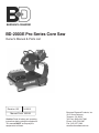
BD-2003E Pro Series Core Saw
Owner’s Manual & Parts List
Revision 105
04.2013
Manual Part# 166526
Caution: Read all safety and operating
instructions before using this equipment.
This manual MUST accompany the
equipment at all times.
Barranca Diamond Products, Inc.
1315 Storm Parkway
Torrance, CA 90501
Toll-Free: (800) 630-7682
Phone: (310) 523-5867
Fax: (310) 257-3063
www.barrancadiamond.com
BD-2003 CORE SAW INTRODUCTION
INTRODUCTION
We at Barranca Diamond want to congratulate you on selecting the BD-2003E Core Saw. We are
certain that you will be pleased with your purchase. Barranca Diamond takes pride in introducing the
finest products in the industry.
Operated correctly, your BD-2003E Core Saw. should provide you with years of quality service. In
order to help you, we have included this manual. This owner’s manual contains information necessary
to operate and maintain your BD-2003E Core Saw safely and correctly. Please take a few minutes to
familiarize yourself with the BD 2003 Core Saw by reading and reviewing this manual.
If you should have questions concerning your BD-2003E Core Saw, please feel free to call our friendly
customer service department at (800) 630-7682.
Regards,
Barranca Diamond
2
BD-2003 CORE SAW SAFETY
Safety Message/Alert Symbols
Safety Warnings
Hazard Symbols
Rules for Safe Operation
Electrical Requirements and Grounding Instructions
Operation & Safety Decals
Safety Decal Locations
TABLE OF CONTENTS
PAGE NO.
4
5
6-8
8-10
11-13
14
15
PRODUCT SPECIFICATIONS
Saw Features
16
UNPACKING & TRANSPORTING
Contents
Transporting
17
17
INSPECTION & SETUP
Pre-start Inspection
Universal Stand Assembly
Cutting Head & Table Setup
Water Pump Preparation
Water Pump Setup
18
18
19
20
21
OPERATION
Setup for Operation
Cutting with the Cutting Head Locked Down
21
22
MAINTENANCE
V-Belt Inspection, Adjustment and Replacement
Diamond Blade Troubleshooting
22-23
24-26
GENERAL PRODUCT INFORMATION
Parts List
Theory of Diamond Blades
Accessories
Contact Information and Limited Warranty
28-32
34
35
36-38
3
BD-2003 CORE SAW SAFETY
Safety precautions should be followed at all times when operating this equipment. Failure to read and
understand the Safety Precaution and Operating Instructions could result in injury to yourself and others.
This Owner’s Manual has been developed to provide complete instructions for the safe and efficient
operation of the BD-2003E Core Saw.
Before using this machine, ensure that the person operating the machine has read and
understands all instructions in this manual.
SAFETY MESSAGE / ALERT SYMBOLS
A safety message alerts you to potential hazards that could hurt you or others. Each safety message is
preceded by a safety alert symbol (
) and one of three words: DANGER, WARNING, or CAUTION.
DANGER
You WILL be KILLED or SERIOUSLY INJURED if you do not follow directions.
WARNING
You CAN be KILLED or SERIOUSLY INJURED if you do not follow directions.
CAUTION
You CAN be INJURED if you do not follow directions. It may also be used to alert against
unsafe practices.
Each message tells you what the hazard is, what can happen, and what you can do to avoid or
reduce injury. Other important messages are preceded by the word NOTICE.
NOTICE
You can cause PROPERTY DAMAGE to your machine if you don’t follow directions.
The safety labels should be periodically inspected and cleaned by the user to maintain good legibility
at a safe viewing distance. If the label is worn, damaged or illegible, it should be replaced.
4
BD-2003 CORE SAW SAFETY
SILICA DUST WARNING
Grinding/cutting/drilling of masonry, concrete, metal and other materials with silica in their composition
may give off dust or mists containing crystalline silica. Silica is a basic component of sand, quartz,
brick clay, granite and numerous other minerals and rocks. Repeated and/or substantial inhalation of
airborne crystalline silica can cause serious or fatal respiratory diseases, including silicosis. In addition, California and some other authorities have listed respirable crystalline silica as a substance
known to cause cancer. When cutting such materials, always follow respiratory precautions.
Use appropriate NIOSH-approved respiratory protection where dust hazard may occur. Paper masks
or surgical masks without a NIOSH approval number are not recommended because they do little to
protect the worker. For more information about respirator programs, including what respirators have
received NIOSH approval as safe and effective, please visit the NIOSH website at:
http://www.cdc.gov/niosh/topics/respirators
Observe OSHA regulations for respirator use (29 C.F.R.§1910.134 and §1503.1).
Visit http://www.osha.gov for more information.
CALIFORNIA PROPOSITION 65 MESSAGE
Some dust created by power sanding, sawing, grinding, drilling, and other construction activities contain chemicals known (to the State of California) to cause cancer, birth defects or other reproductive
harm. Some examples of these chemicals are:
• Lead, from lead-based paints
• Crystalline silica from bricks, cement and other masonry products
• Arsenic and chromium, from chemically treated lumber
For further information, consult the following sources:
http://www.osha.gov/dsg/topics/silicacrystalline/index.html
http://www.cdc.gov/niosh/docs/96-112/
http://oehha.ca.gov/prop65/law/P65law72003.html
http://www.dir.ca.gov/Title8/sub4.html
Your risk from these exposures varies depending on how often you do this type of work. To reduce
your exposure to these chemicals, work in a well-ventilated area, and work with approved safety
equipment, such as the dust masks that are specially designed to filter out microscopic particles.
Where use of a dust extraction device is possible, it should be used. To achieve a high level of dust
collection, use an industrial vacuum cleaner.
5
BD-2003 CORE SAW
SAFETY
DO NOT touch hot engine components while the machine is running or immediately after
operating.
This hazard symbol means “Over Speed.”
((
))
NEVER touch the power cord with wet hands or while standing in water when it is connected to a power source.
RULES FOR SAFE OPERATION
DANGER
Failure to follow instructions in this manual may lead to serious injury or even death! This equipment is
to be operated by trained and qualified personnel only! This equipment is for industrial use only.
The following safety guidelines should always be used when operating the BD-2003E Core Saw.
GENERAL SAFETY
• DO NOT operate or service this equipment before reading this entire manual.
Read and understand all warnings, instructions and controls on the machine.
• This equipment should not be operated by persons under 18 years of age.
• NEVER operate this equipment without proper protective clothing, shatterproof glasses, steel-toed boots and other protective devices required by the job.
• NEVER operate this equipment when not feeling well due to fatigue, illness or taking medicine.
• NEVER operate this equipment under the influence of drugs or alcohol.
• Whenever necessary, replace nameplate, operation and safety decals when they become difficult
to read.
• ALWAYS check the machine to see that keys and adjusting wrenches are removed from the machine before it is turned on.
• ALWAYS wear proper respiratory, head, ear and eye protection equipment when operating this machine.
• ALWAYS store equipment properly when it is not being used. Equipment should be stored in a clean, dry location out of the reach of children.
6
BD-2003 CORE SAW ON / OFF
•
• SAFETY
Turn the “ON/OFF” switch to the “OFF” position prior to connecting the machine to the power source. NEVER leave the machine unattended. Turn off electric motor
when unattended. Know how to stop the machine quickly in case of emergency.
NEVER try to stop a moving blade with you hand.
CAUTION must be observed while servicing the machine. Rotating parts can cause injury if
contacted. Have all service performed by competent service personnel.
• ALWAYS ensure that the machine is on level ground before using. Keep proper footing and
balance at all times by not overreaching. Keep hands, feet, hair and clothing away from moving parts to prevent injury.
• Operate this machine only in well ventilated areas. NEVER operate this machine in an
explosive atmosphere.
Establish a training program and give a copy of this manual to operators of this equipment. If you
need extra copies, call TOLL-FREE (800) 421-5830.
SAW BLADE SAFETY
ALWAYS keep area around the machine clear of obstructions and clear the work area of
unnecessary people. Keep all body parts away from the blade and all other moving parts.
Before starting the machine, check that all guards are in position and correctly fitted. NEVER
allow blade exposure from the guard to be more than 180 degrees. DO NOT operate this
machine with the transmission guard removed.
•
Inspect the blade, flanges and shafts for damage before installing the blade. NEVER use damaged
or worn blade flanges.
•
Inspect the blade, flanges and size shown for each blade size. DO NOT exceed maximum blade speed shown, as excessive speed could result in blade breakage. Use ONLY blades marked with a maximum operating speed greater than the blade shaft speed. Verify speed and saw drive
configuration by checking blade shaft RPM and pulley diameters and blade flange diameters.
• Use the correct blade for the type of work being done. Use only reinforced abrasive blades or steel center diamond blades and flanges supplied with the saw or manufactured for use on concrete saws. DO NOT use carbide-tipped blades. Check with the blade manufacturer if you do not know if blade is correct.
•
Make sure the blade and flanges are clean and free of dirt and debris before mounting the blade on the saw. Verify the blade arbor hole matches the machine spindle before mounting the blade. ALWAYS mount the blade solidly and firmly. Wrench tighten the arbor nut.
•
ALWAYS feed work into a blade or cutter against the direction of rotation. A blade or cutter should always be installed such that rotation is in the direction of the arrow imprinted on the side of the blade or cutter.
7
BD-2003 CORE SAW
SAFETY
•
ALWAYS cut in a straight line. DO NOT cut deeper than 1” per pass with a dry blade. Step cut to achieve deeper cuts. NEVER force, jam, wedge or twist the blade in a cut. DO NOT grind on the side of the blade.
•
DO NOT touch a dry cutting blade immediately after use. These blades require several minutes to cool after each cut. DO NOT use a blade that has been overheated (Core has a bluish color).
• NEVER stand on the tool. Serious injury could occur if a power tool is tipped, or if a cutting tool is unintentionally contacted.
• Become familiar with the controls of the machine before operating. Know how to stop the
machine quickly in case of emergency.
• ALWAYS secure work. Clamps or a vise should be used to hold work whenever practical.
Keeping your hands free to operate a power tool is safer.
• ALWAYS disconnect AC power plug from power source before moving, cleaning or servicing the machine.
• NEVER leave a tool running unattended. Do not leave a tool until it comes to a complete stop.
ALWAYS turn a power tool OFF when leaving the work area, or when a cut is finished.
• Make sure the OFF/ON power switch on the electric motor is always in the OFF position before
inserting the machine’s power plug into an AC receptacle.
• Operate electric motor only at the specified voltage indicated on the nameplate.
• NEVER disconnect any “emergency or safety devices.” These devices are intended for
operator safety. Disconnection of these devices can cause severe injury, bodily harm or even death! Disconnection of any of these devices will void all warranties.
• Unauthorized equipment modifications will void all warranties. Manufacturer does not assume
responsibility for any accident due to equipment modifications.
• NEVER use accessories or attachments, which are not recommended by MK Diamond for this equipment. Damage to the equipment and/or injury to user may result.
•
Replace damaged cutting blade before operating.
•
NEVER try to stop a moving blade with your hand.
MOTOR OVERLOAD SAFETY
((
))
• If the machine goes off unexpectedly, the motor’s overload cutout may have been
activated. In this case, unplug the machine from the power supply and wait until the
motor and overload cutout have cooled down.
8
BD-2003 CORE SAW SAFETY
MAINTENANCE SAFETY
• NEVER lubricate components or attempt service on a running machine.
• Keep the machinery in proper running condition. Clean the machine after each day’s use. Follow instructions for changing accessories. Inspect tool periodically and, if damaged, have repaired by authorized service facility.
SET UP & TRANSPORTATION SAFETY
•
ALWAYS use caution and follow the instructions when lifting and transporting this machine.
•
ALWAYS tie down the machine when transporting. DO NOT tow this machine behind a vehicle.
•
NEVER transport with the blade mounted on the machine.
•
Lift only from the lift bail.
ELECTRICAL SAFETY
•
Make sure power cords are the proper size and in good condition. DO NOT allow a
power cord to become damaged. NEVER allow the power cord to come into contact with water, fluids, heat, oil or sharp edges. ALWAYS ensure that the electrical extension cord is not trapped underneath the machine.
•
Make sure the OFF/ON power switch on the electric motor is always in the OFF position before inserting the machine’s power plug into an AC receptacle.
•
Operate electric motor only at the specified voltage indicated on the nameplate.
• ALWAYS make sure electric powered machines are plugged into a properly grounded circuit. DO NOT replace the motor with any motor that does not have a special grounding connection.
•
DO follow all electrical codes in your area. ALWAYS check for buried electrical cables before sawing. If unsure, contact the local utilities.
•
ALWAYS disconnect AC power plug from power source before moving or servicing the machine.
•
NEVER disconnect any “emergency or safety devices.” These devices are intended for operator safety. Disconnection of these devices can cause severe injury, bodily harm or even death!
Disconnection of any of these devices will void all warranties.
•
Unauthorized equipment modifications will void all warranties. Manufacturer does not assume
responsibility for any accident due to equipment modifications.
•
NEVER use accessories or attachments, which are not recommended by Barranca Diamond for this equipment. Damage to the equipment and/or injury to user may result.
9
BD-2003 CORE SAW SAFETY
ELECTRICAL REQUIREMENTS AND GROUNDING INSTRUCTIONS
))
ON
((
In order to prevent electrical shock and injury, the following electrical safety precautions and symbols
should be followed at all times!
WARNING
In case of a malfunction or breakdown, grounding provides a path of least resistance for electrical
current to reduce the risk of electric shock. This tool is equipped with an electric cord which has an
equipment-grounding conductor and a grounding plug. The plug must be plugged into a matching
outlet that is properly installed and grounded in accordance with all local codes and ordinances.
• DO NOT modify the plug provided - if it will not fit the outlet, have the proper outlet
installed by a qualified electrician.
• Improper connections of the equipment-grounding conductor can result in a risk of electric shock. The equipment-grounding conductor is the insulated conductor that has an outer surface that is green, with or without yellow stripes. If repair or replacement of the electric cord or plug is necessary, DO NOT connect the equipment-grounding conductor to a live terminal.
• Check with a qualified electrician or service personnel if the grounding instructions are not completely understood, or if in doubt as to whether the tool is properly grounded.
• Use only 3-wire extension cords that have 3-prong grounding plugs and 3-pole receptacles that accept the tool’s plug.
• Repair or replace a damaged or worn cord immediately.
This tool is intended for use on a circuit that has an outlet that looks like the one shown in Sketch A.
The tool has a grounding plug that looks like the plug illustrated in Sketch A. A temporary adapter,
which looks like the adapter illustrated in sketches B and C, may be used to connect this plug to a
2-pole receptacle as shown in Sketch B, if a properly grounded outlet is not available. The temporary
adapter should be used only until a properly grounded outlet can be installed by a qualified electrician. The green-colored rigid ear, plug, and the like, extending from the adapter, must be connected
to a permanent ground, such as a properly grounded outlet box.
Metal Screw
Grounding
Pin
(A)
Cover of
Grounded
Outlet Box
(B)
ADAPTER
(C)
Grounding
Means
Grounding
Pin
(D)
Circuit and Adapter Information
NOTE:
Use of a temporary adapter is not permitted in Canada.
NOTE:
If permanently connected, this tool should be connected to a grounded metal permanent
wiring system; or to a system having an equipment - grounding conductor.
10
BD-2003 CORE SAW SAFETY
WARNING
To reduce the risk of electrocution, keep all connections dry and off the ground.
A Ground Fault Circuit Interrupter (GFCI) should be provided on the circuit(s) or outlet(s) to be used
for this machine. Receptacles are available having built-in GFCI protections and may be used for this
measure of safety.
When using an extension cord, the GFCI should be installed closest to the power source, followed by
the extension cord and lastly, the machine.
WARNING
The pump requires a GFCI. To reduce risk of electric shock when operating the machine with the
pump plugged into the 3-pole receptacle on the motor, connect the saw to a GFCI outlet. See the
pump manual and informational tags enclosed separately for all pump information.
CAUTION
))
Shock Hazard. For replacement, use only an identical pump, model 2E-38NY part #114769.
NOTE: Do not run pump dry. Also, be sure to disconnect and remove the pump when cutting dry.
((
ON
WARNING
To avoid the possibility of the appliance or plug receptacle getting wet, position the machine to one side of a wall mounted receptacle. This will prevent water from dripping into the receptacle or plug. A
"drip loop," shown in the picture below, should be arranged by the user to properly position the power cord relative to the power source. Use the drip loop as a way to prevent GFCI and plug from getting
wet.
The "drip loop" is that part of the cord below the level of the receptacle (or the connector, if an extension cord is used). This method of positioning the cord prevents the travel of water along the power
cord and coming in contact with the receptacle.
If the plug or receptacle gets wet, DO NOT unplug the cord. Disconnect the fuse or circuit breaker
that supplies power to the tool. Then unplug and examine for presence of water in the receptacle.
Power
Cord
Power
Tool
Supporting
Surface
Drip Loop
Drip Loop Information
11
BD-2003 CORE SAW SAFETY
WARNING
Use only extensions cords that are intended for outdoor use. These extension cords are identified
by a marking “Acceptable for use with outdoor appliances; store indoors while not in use.” Use only
extension cords having an electrical rating not less than the rating of the product. Do not use damaged extension cords. Examine extension cords before using and replace if damaged. Do not abuse
extension cords and do not yank on any cord to disconnect. Keep cords away from heat and sharp
edges. Always disconnect the extension cord from the receptacle before disconnecting the product
from the extension cord.
((
WARNING
ON
To reduce
the
risk of electrocution, keep all connections dry and off the ground. Do not touch the
))
plug with wet hands.
WARNING
Use of undersized extension cords result in low voltage to the motor that can result in motor burnout
and premature failure. MK Diamond warns that equipment returned to us showing signs of being run
in a low voltage condition, through the use of undersized extension cords,will be repaired or replaced
totally at the customer’s expense. There will be no warranty claim.
To choose the proper extension cord,
• Locate the length of extension cord needed in the table below.
• Once the proper length is found, move down the column to obtain the correct AWG size required for that length of extension cord.
EXTENSION CORD LENGTH
115V
25'
50'
75'
100'
150'
200'
250V
50'
100'
150'
200'
300'
400'
0-5
16
16
16
14
12
12
5.1 - 8
16
16
14
12
10
•
8.1 - 12
14
14
12
10
•
•
12.1 - 15
12
12
10
10
•
•
15.1 - 20
10
10
10
•
•
•
Nameplate
Amperes
12
BD-2003 CORE SAW LOCK OUT METHOD
In order to help prevent accidental starting and to help
make your work area “kidproof,” this machine is provided
with a means to deactivate the functioning of the motor
switch. The switch is equipped with a lockout tab that can
be used with a lock to prevent movement of the switch.
With the switch unable to move the motor cannot be turned
on. Removing the lock reactivates the switch.
Lock Out
13
SAFETY
BD-2003 CORE SAW SAFETY
OPERATION & SAFETY DECALS
The BD-2003E is equipped with a number of safety decals (Figure 5) provided for operator safety and
maintenance information. Should any of these decals become unreadable, replacements can be obtained by calling (800) 630-7682.
!
WARNING
FOR INFORMATION ON
Masonry, concrete, metal and other materials with silica in their composition
may give off dust or mists containing crystalline silica. Silica is a basic
component of sand, quartz, brick clay, granite and numerous other minerals
and rocks. Repeated and/or substantial inhalation of airborne crystalline silica
can cause serious or fatal respiratory diseases, including silicosis. In addition,
California and some other authorities have listed respirable crystalline silica as
a substance known to cause cancer.
SERVICE OR
WARRANTY
PLEASE CALL
1-800-474-5594
Decal A
Decal B
! WARNING
!
In the event of
blade failure,
replace blade
guard
immediately.
DO NOT operate this
equipment before
reading the owner’s
manual!
Decal D
!
NOTICE
Most motor problems are caused by improper
voltage and extension cords. Cord should be
one-piece and short as possible. Cord
selection should match the following table.
WARNING
Decal E
!
DO NOT
operate without
guards in place.
Decal C
! CAUTION
DO NOT lift
blade guard
when engine
is running.
Decal F
BD-2003E Safety Decal Sheet, Part No. 166011
1-2 H.P.
115v 230v
25’ 100’ Max. Cord Length No. 12 Wire
50’ 150’ Max. Cord Length No. 10 Wire
75’ 250’ Max. Cord Length No. 8 Wire
Decal G
14
CAUTION
BD-2003 CORE SAW SAFETY DECAL LOCATIONS
Decal B
Decal C
Decal D
Decal A
Decal G
Decal E
Decal F
BD-2003E Safety Decal Locations
Decal
Location
Description
A
Motor - Front
Warning - Silica
B
Motor - Rear
Service or Warranty Information
C
Belt Guard
Caution - General Safety Information
D
Motor - Front
Warning - Read manual
E
Blade Guard
Warning - Replace blade guard
F
Blade Guard
Caution - General Safety Information
G
Motor - Front
Notice - Extension Cord Information
15
SAFETY
BD-2003 CORE SAW PRODUCT SPECIFICATIONS
SAW FEATURES
The BD-2003E Pro Series is a versatile Core Saw. Operated and used according to this manual, the
BD-2003E will provide years of dependable service.
GENERAL DESCRIPTION
These precision built saws are designed for rapid and accurate sawing of exploratory core specimens. The specialty designed 14” segmented diamond blade allows cutting of hard or dense rock
samples and engineered materials. The integral core holder provides for rapid and safe cutting of
cylindrical core samples. Adjustable height cutting head accommodates specimen sizes between 1”
and 5” in diameter.
MOTOR SPECIFICATIONS
Motor specifications for the BD-2003E are listed in the table below.
Motor
Baldor 3HP
Voltage
230V
Motor RPM
3,450
Blade RPM
3,100
Blade Capacity
14” (350mm)
Arbor
1” (25mm)
Table Travel
29”
Max. Core Sample Length
12”
Max. Core Sample Diameter
5”
Min. Core Sample Diameter
1”
Weight
172 lbs.
L x W x H (in)
34” x 25” x 32”
L x W x H (mm)
940 x 584 x 737
Part #
158751
* The BD-2003E Pro Series is also available with a 50hz motor.
THERMAL OVERLOAD PROTECTION
The motor is protected by a thermal overload equipped with a manual reset.
BLADE CAPACITY
The BD-2003E is designed for use with a 14-inch diameter segmented wet or dry Barranca Diamond
blade with a .110 to .375 inch cutting width.
NOTE:
The BD-2003E is not designed to cut plastic or ferrous (metal) material.
16
BD-2003 CORE SAW UNPACKING & TRANSPORTING
UNPACKING
Your BD-2003E has been shipped from the factory thoroughly inspected. Only minimal assembly is required.
CONTENTS
In your container, you will find one (1) BD-2003E frame and water basin, one (1) cutting table, one
(1) 10-inch wet cutting lapidary blade, one (1) adjustable cutting guide, one (1) electric water pump,
one (1) pump discharge fitting, one (1) cooling transfer tube, one (1) flow adjusting clamp, one (1)
drain plug, one (1) blade wrench, one (1) stand, one (1) rock vise, one (1) stand, one (1) owner's
manual, one (1) pump manual and one (1) warranty card.
One BD-2003E
One Movable
Cutting Table
10" Wet Cutting
Lapidary Blade
One Adjustable
Cutting Guide
One Pump
Discharge Fitting
One Cooling
Transfer Tube
One Flow
Adjusting Clamp
One Drain Plug
One Wrench
One Pump
Manual
One Warranty
Card
www.barrancadiamond.com
One Electric
Water Pump
BD-2003E PRO SERIES
CORE SAW
OWNER’S MANUAL
Manual Part# 166526
Revision 104
10.2012
Caution: Read all safety and operating instructions
before using this equipment. This manual MUST
accompany the equipment at all times.
Rock Vise
(Part # 8300015)
Stand
(Part # 153331)
One Owner’s
Manual
17
BD-2003 CORE SAW TRANSPORT
TRANSPORTING
CAUTION
The BD-2003E weighs approximately 162 lbs. Use proper lifting techniques and care when lifting
and transporting. NEVER transport the BD-2003E with water in the water basin.
NOTE:
Lock the Cutting Head in the “DOWN” position and remove the Movable Cutting Table
when transporting. The BD-2003E is equipped with forklift brackets for lifting and moving
the saw.
The BD-2003E is designed with legs in the front and rear for ease of transport. To transport:
1.
2.
3.
4.
Verify the Movable Cutting Head is locked in the down position and the Movable Cutting Table is removed.
Position two people on either side of the saw.
From the side, grasp the front and rear of the saw.
Lift and transport the saw to the desired work location.
Cutting Head Locked Down
Lift Point
Remove Movable Cutting Table
Lift Point
Forklift Bracket
Forklift Bracket
Transporting the saw
18
BD-2003 CORE SAW INSPECTION & SETUP
PRE-START INSPECTION
Prior to beginning work, a pre-start inspection of the saw should be performed.
1.
2.
3.
4.
5.
Ensure the ON/OFF switch is in the OFF position.
Verify the Movable Cutting Table moves freely along the Guide Rails.
Inspect the Diamond Blade for damage, cracks and debonding; verify the blade is
correct for the material being cut.
Inspect the Pump Assembly for damage - ensure the cord is free of cracks or cuts.
Inspect the BD-2003E for damage - ensure all cords are free of cracks or cuts.
Inspect Blade for damage
Inspect Pump for damage
ASSEMBLY
NOTE:
If using the MK Diamond Stand, follow the following steps.
(A )
Open the stand and place
it on flat surface.
(B)
Set saw on stand as
shown.
19
(C)
Ensure pins are placed
through holes on frame.
BD-2003 CORE SAW SETUP & ASSEMBLY
MOVABLE CUTTING TABLE INSTALLATION
(A)
While holding the front, position
movable Cutting Table roller wheels
above Guide Rails.
(B)
Seat movable Cutting Table roller
wheels on saw Guide Rails.
(C)
Verify movable Cutting Table is
seated correctly by moving table
back and forth.
CONNECTING THE WATER PUMP
CAUTION
To prevent possibility of electrical shock, the BD-2003E must be de-energized
when connecting the water pump.
NOTE: To prevent pump damage, the Water Pump must be disconnected if cutting with a Dry Blade.
(A)
Connect the Cooling Transfer
Tube to the inlet connection of
the Blade Guard.
(B)
Connect the Water Pump power
cord to the receptacle found on
motor.
WATER PUMP PREPARATION
(A)
Install Water Pump Discharge Fitting.
(B)
Press one end of the Cooling
Transfer Tube into the Water
Pump Discharge Fitting.
20
(C)
Slide Cooling Flow Adjusting
Clamp on to the Cooling Transfer Tube.
BD-2003 CORE SAW OPERATION
WATER PUMP SETUP FOR OPERATION
The Water Pump can be setup for operation in two ways: External water source or Re-circulation.
NOTE: If using a dry blade for operation, DO NOT connect the water pump.
EXTERNAL WATER SOURCE
This is the preferred method of cooling.
1. Verify or remove the Drain Plug form the Water Pan.
2. Place the Water Pump in an external container.
3. Fill the external container until water completely covers the Water Pump suction.
RE-CIRCULATION
NOTE: When using the re-circulation method, the water should be changed often for longer pump life.
1. If not installed, install the Drain Plug into the Water Pan.
2. Place the Water Pump in the back of the Water Pan.
3. Fill the Water Pan until water completely covers the Water Pump suction.
SETUP FOR OPERATION
Before powering or starting, check for damage that could prevent this equipment form proper operation
or performing its intended function. Check for binding and alignment of moving parts. Check for damaged, broken or missing parts.
1. Verify the ON/OFF switch is in the OFF position.
2. Before connecting the BD-2003E to a power supply, be sure the voltage, cycle and phase of the job site power source meet the requirements of the table below.
Voltage
Cycle
Phase
230V
60Hz
1-phase
3. If using an extension power cord, make sure the length and wire gauge correspond to the
requirements.
4. Listed in the Table on Page 12. An extension power cord that is too small in wire gauge (diameter), or too long in length, will cause the motor overheat and could cause premature failure.
5. DO NOT cover the motor vents as this could lead to motor overheating.
* The BD-2003E Pro Series is also available with a 50Hz motor.
NOTE: In order to avoid breaker tripping, a 20-amp circuit breaker should be used.
PORTABLE GENERATOR
WARNING
8KW
120/240 Volts
66.7/33.3 Amps
21
Single Phase
BD-2003 CORE SAW OPERATION & MAINTENANCE
CUTTING WITH THE CUTTING HEAD LOCKED DOWN
This method is preferred when cutting small objects.
CAUTION
Cut in smooth, even strokes. DO NOT force the saw to cut.
1. If locked, loosen the Cutting Head Locking Knob by turning counter-clockwise.
2. Lower the Cutting Head until the Blade touches the Protective Wooden Strip.
3. Lock the Cutting Head in the “Down” position by turning clockwise.
(A)
If locked, loosen Cutting Head
knob by turning counter-clockwise
BELT INSPECTION, ADJUSTMENT AND REPLACEMENT
The BD-2003E is designed with dual power transmission belts. In order to ensure the BD-2003E operates at peak efficiency, the two belts should be inspected monthly, and changed if they show signs
of damage and/or excessive wear.
NOTE: When new belts are installed, they should be inspected and re-tensioned after the first 48 hours of operation.
1. Inspect the belts for cracks, fraying separation and wear
2. Lower the Cutting Head until the Blade touches the Protective Wooden Strip.
3. Lock the Cutting Head in the “Down” position by turning clockwise.
(A)
Inspect belts
(B)
Check tension
22
(C)
Loosen Mounting Bolts
BD-2003 CORE SAW MAINTENANCE
BELT INSPECTION, ADJUSTMENT AND REPLACEMENT
4. Loosen the Motor Adjustment Strap using a 9/16 inch wrench. Rotate counter clockwise to loosen (A).
5. Push the Motor forward to loosen the belt (B).
6. Remove the old belt (C).
(A)
Loosen Motor Strap
(B)
Push Motor forward
(C)
Remove old belt
7. Install the new belt (C).
8. Verify the belt is seated in the groove of the pulley (D).
9. Tighten the Motor Adjustment Strap using a 9/16 inch wrench. Rotate clockwise to tighten belt and remove slack (E).
(D)
Install new belt
(E)
Seat belt in pulley groove
(F)
Tighten Motor Strap
10. Check the belt for proper tension (G).
11. Repeat steps 8 and 9 until proper belt tension is achieved (H).
12.Tighten the Motor Mounting Bolts using 1/2 inch wrench. Rotate clockwise to tighten (I).
(G)
Check tension
(H)
Continue adjustments
23
(I)
Tighten Motor Bolts
BD-2003 CORE SAW TROUBLESHOOTING
BLADE WILL NOT CUT
1. 2. 3. Blade is too hard for material being cut.
Use a softer bonded blade. Select proper blade specification for material being cut.
Blade has become dull as a result of being used on too hard a material.
Improper blade specification; blade is too hard for the material being cut. Use a softer bonded blade to reduce operating stresses.
“Dull” blade.
“Open” blade by dressing segment on abrasive block.
UNEVEN SEGMENT WEAR
1. Insufficient water (usually on one side of blade).
Flush out water system and check flow and distribution to both sides of blade.
2. Equipment defects cause the segments to wear unevenly.
Replace bad bearings, worn arbor shaft or misalignment to spindle.
Concrete saws: engine must run smoothly to prevent harmonic vibration.
3. Saw is misaligned.
Check saw head alignment for squareness both vertically and horizontally.
SHORT BLADE LIFE
1.
2.
Blade bond or matrix is too soft.
Use a harder matrix blade.
Overheating due to lack of water.
Check water feed lines to make sure flow is adequate on both sides of blade.
UNDERCUTTING THE STEEL CENTER
1.
2.
Abrasion of steel center due to highly abrasive fines generated during cutting.
Use as much water as possible to flush out fines generated during cutting or use water-retardant cores.
Cutting through material into sub-base.
Wear-retardant cores are not always the ultimate solution to eliminating undercutting. Your best defense is to always provide an adequate water flow to the steel center area immediately
adjacent to the segment. This is especially important when making deep cuts.
ARBOR HOLE OUT-OF-ROUND
1.
2.
3.
4.
Blade collar is not properly tightened, permitting blade rotation or vibration on the shaft.
Tighten the shaft nut with a wrench to make certain that the blade is adequately secured.
Blade collars are worn or dirty, not allowing proper blade clamping.
Clean blade collars, making sure they are not worn.
Blade is not properly mounted.
Make certain the blade is mounted on the proper shaft diameter before tightening shaft nut. Ensure the pin hole slides over drive pin. Make sure that drive pin is in pin hole.
Loose belt on saw.
Tighten belts. Check to see if arbor on saw is running true.
24
BD-2003 CORE SAW TROUBLESHOOTING
LOSS OF TENSION
1.
2.
3.
Steel center has been overheating as a result of blade spinning on arbor.
Check water flow, distribution and lines. Tighten the blade shaft nut. Make certain the drive pin is functioning (on concrete saws).
Steel center has been overheating from rubbing the side of material being cut.
Make certain blade RPM is correct so the blade operates at its tensioned speed. Tune engine according to manufacturer’s manual.
Unequal pressure at blade clamping collars.
Blade clamping collars must be identical in diameter and the recommended size.
1.
2.
3.
Shaft bearings are worn (masonry and concrete).
Install new blade shaft bearings or blade shaft, as required.
Engine is not properly tuned on concrete saw, causing surges in blade rotation.
Tune engine according to manufacturer’s manual.
Blade arbor hole is damaged from previous incorrect mounting.
Replace worn shaft or mounting arbor bushing. Bond is too hard for material, causing a “rounding” and wearing one half of the blade more than the other. Make certain that drive pin is functioning. Use proper blade specification.
BLADE WORN OUT-OF-ROUND
BLADE WOBBLES
SEGMENT LOSS
1. Blade runs at improper speed.
Check for bad bearings, bent shaft, or worn mounting arbor. Speed of the saw is either too fast or too slow for the size of the blade. RPM of the saw should be verified to the specific speeds established by the NASI Standards for
minimum and maximum blade speeds; make certain that blade shaft is
running at recommended RPM to match tensioned speed of blade. Should the blade continue to wobble after verification of the saw RPM, then the blade should be returned to the manufacturer to be retensioned and flattened.
2. Blade collar diameters are not identical.
Check blade collar discs to make sure they are clean, flat and of correct diameter.
3. Blade is bent as a result of dropping or being twisted in the cut during
operation.
Blade should be returned to the manufacturer to be retensioned and flattened.
4. Loss of blade tension.
(See Loss of Tension)
1. Overheating due to lack of water.
Check water feed lines and make sure water flow is adequate on both sides of blade.
2. Steel center is worn from undercutting.
Use sufficient water to flush out the cut.
3. Defective blade collars are causing blade misalignment.
Clean blade collars or replace is collars are under recommended diameter.
4. Blade is cutting out of round, causing a pounding motion.
Replace worn bearings; realign blade shaft or replace worn blade mounting arbor.
5. Improper blade tension.
Ensure blade is running at correct RPM. Blade is tensioned for correct RPM. Tune engine according to manufacturer’s manual.
25
BD-2003 CORE SAW TROUBLESHOOTING
CRACKS IN STEEL CENTER
1. Blade flutters in cut as a result of blade losing tension.
Tighten the blade shaft nut. Make sure blade is running at proper tensioned speed and that drive pin is functioning properly.
2. Blade specification is too hard for the material being cut.
Use a softer blade bond to eliminate stresses that create cracks.
3. Bad blade shaft bearing.
Replace blade shaft bearing.
4. Overheating due to lack of water.
Check water feed lines and make sure flow is adequate on both sides of blade.
SEGMENT CRACKS
1.
2.
Blade is too hard for material being cut.
Use a blade with a softer bond.
Blade being “forced” through the cut causing chattering.
Run Saw at normal speed. “Open” blade by sharpening in abrasive material.
26
NOTES
27
BD-2003 CORE SAW ITEM
DESCRIPTION
PARTS LIST
PART #
QTY.
Assembly, Frame, Brick Saw (Barranca)
1
FRAME, WELDMENT (BARRANCA)
158845-BD
1
2
PLUG, RUBBER DRAIN, NO LOGO
153439-NL
1
3
LABEL, BD CORE SAW
166494
2
166011
1
4
LABEL, MASONRY LABEL SHEET
Assembly, Upright, Left
1
POST (COMP) POST (RAW)
158846-BD, 231022
1
2
SCREW, 5/16-18 X 1-3/4, HEX HEAD CAP
150919
4
3
WASHER, 5/16 SPLIT LOCK
151747
4
4
WASHER, 5/16 SAE FLAT
151754
8
101196
4
5
NUT 5/16-18 HEX
6
STUD, SPRING RETAINING
160066
1
7
SCREW, 5/16-18 X 1-1/2, HEX HEAD CAP
152467
1
8
WASHER, 5/16 SPLIT LOCK
151747
1
9
WASHER, 5/16 SAE FLAT
151754
1
1
POST (COMP) POST (RAW)
158846-BD, 231022
1
2
SCREW, 5/16-18 X 1-3/4, HEX HEAD CAP
150919
4
3
WASHER, 5/16 SPLIT LOCK
151747
4
4
WASHER, 5/16 SAE FLAT
151754
8
Assembly, Upright, Right
5
NUT 5/16-18 HEX
101196
4
6
HANGER, WRENCH
153945
1
7
SCREW, 3/8-16 X 1-3/4, HEX HEAD CAP
150920
1
8
WASHER, 3/8 SAE FLAT
150923
1
9
WASHER, 3/8 SAE SPLIT LOCK
150925
1
10
CLAMP, CUSHION LOOP 1/2” (ELEC.)
152471
1
11
SCREW, 1/4-20 X 2 HEX HEAD CAP
158282
1
12
WASHER, 1/4 SAE FLAT
151915
2
13
WASHER, 1/4 SPLIT LOCK
152591
1
151893
1
14
NUT 1/4-20 HEX
28
BD-2003 CORE SAW ITEM
DESCRIPTION
PARTS LIST
PART#
QTY.
Assembly, Cutting Head (elec)
1
HEAD, MOTOR MOUNT (COMP)
160346-BD
1
2
CLAMP, MOTOR MOUNT (COMP), BARRANCA
160397-BD
2
3
HOUSING, PIVOT SHAFT
157979
1
4
SCREW, 5/16-18 X 1-1/4, HEX HEAD CAP
153950
4
5
SHAFT, THREADED
150585
1
6
BEARING, PIVOT SHAFT
140004
1
7
HANDLE
139931
1
8
GRIP, HANDLE
139949
1
9
SCREW, 3/8-16 X 3/4, HEX HEAD CAP
152507
2
10
STRAP, MOTOR ADJUSTMENT
150584
1
11
SCREW, 3/8-16 X 3-1/2 HEX HEAD CAP
153147
1
12
WASHER, 3/8 SAE FLAT
150923
1
13
SCREW, 5/16-18 X 1-3/4, HEX HEAD CAP
160948
4
14
SCREW, 5/16-18 X 2” HEX HEAD TAP
157938
2
15
PIN, SPLIT WRIST
151358
1
16
BUSHING, PLASTIC
156441
2
17
WASHER, 3/8 SPLIT LOCK
150925
2
1
SHAFT, PIVOT
154147
1
2
COLLAR, PIVOT SHAFT
140012
2
3
BRACKET, STAY-LEVEL
160068
1
4
SPRING, TORSION (4 COIL)
160069
1
5
BRACKET, PIVOT SHAFT RETAINING
160070
1
6
SCREW, 5/15-18 X 1 BUTTON HEAD
151698
4
7
WASHER, 5/16 SAE FLAT
151754
4
8
WASHER, 5/16 SPLIT LOCK
151747
4
Assembly, Pivot Shaft
Assembly, Cutting Head Height Adjustment
1
BAR, CUTTING HEAD HEIGHT ADJUSTMENT
166868
1
2
SCREW, 3/8-16 X 1 HEX HEAD CAP
152507
1
3
WASHER, 3/8 SPLIT LOCK
150925
1
4
WASHER, 3/8 SAE FLAT
150923
2
29
BD-2003 CORE SAW ITEM
DESCRIPTION
PARTS LIST
PART #
QTY.
Assembly, Blade Shaft
1
ASSY, BLADE SHAFT
154636-BD
1
2
PULLEY, 1 GROOVE, 2-1/2 X 3/4
133140
1
3
SCREW, 5/16-18 X 3/8 SET
157083
2
KEY, 1-1/8 X 3/16
150344
1
1
BLADE GUARD, (COMP) BARRANCA
158886-BD
1
2
STUD, BLADE GUARD PIVOT
150581
1
4
Assembly, Blade Guard
3
NUT, 1/2-20 LOCK
153943
1
4
SHIM, 1/2
153952
1
5
ROD, ADJUSTMENT BLADE GUARD
160076
1
6
BALL JOINT ROD END, STAMPED, 3/8-24
156521
2
160077
2
7
NUT, JAM 3/8-24
8
SCREW, 3/8 X 1/2 SHOULDER, 5/16-18 X 1/2 THREAD
160078
2
9
VALVE, MINIATURE BALL, 1/4 MALE/FEMALE
231248
1
157500-RW
1
231248
1
231055
1
10
TAG, SERIAL NUMBER, BLANK
Assembly, Water Control Valve
1
VALVE, BALL, 1/4 M X 1/4 F
2
ELBOW, 90 DEGREES, BRASS
Assembly, Splash Guard
1
GUARD, SPLASH
160310-NL
1
2
SCREW, 1/4-20 X 1/2, HEX HEAD CAP
152608
1
3
WASHER, 1/4 SAE FLAT
151915
2
1
BELT GUARD INNER (COMP), BARRANCA
150590-BD
1
2
WASHER 3/8 SAE FLAT
150923
2
3
BELT GUARD OUTER (COMP), BARRANCA
158867-BD
1
1
CASTING, TABLE (COMP), CORE SAW, BARRANCA
166310
1
2
STOP-RULE, TABLE
134387
1
3
SCREW, 1/4-20 X 3/4 HEX HEAD
152370
4
Assembly, Belt Guard
Assembly, Table
30
BD-2003 CORE SAW ITEM
DESCRIPTION
PARTS LIST
PART#
QTY.
Assembly, Table cont...
4
NUT, 1/4-20, KEPS
153491
4
5
WHEEL, ROLLER
133090
4
6
NUT, 5/16 -18 KEPS
153942
4
7
WOOD STRIP, TABLE INSERT
158283
1
8
SCREW, #6 X 1 BUGLE HEAD PHILLIPS
159906
2
9
JIG, CORE SAW
161122
1
10
NUT, HEX, 3/8 - 16
101188
4
11
WASHER, FLAT, 3/8 SAE
150923
4
12
WASHER, SPLIT LOCK, 3/8
150925
4
13
SCREW, HEX HD CAP, 3/8-16 X 1
152507
4
ROD, SPLASH CURTAIN
162707-BD
1
PUMP, 230V WATER
114769
1
128397
1
Assembly, Curtain (Barranca)
1
Assembly, Pump Electric
1
2
FITTING, PLASTIC, 1/4 FNPT X 1/4 BARB
3
HOSE,VINYL 1/4 ID
132951
6FT.
4
CARTON, WATER PUMP G-150A
154016
1
5
INSERT, FOAM WATER PUMP G-150A
154017
1
6
PLUG, IEC60320 MALE
166278
1
Assembly, Accessory Pack, (Barranca Core Saw)
1
WRENCH, MASONRY SAW
134056
1
2
CARTON, ACCESSORY
153575
1
3
INSERT, ACCESSORY
153576
1
4
WARRANTY CARD
166528
1
166526
1
166293
1
5
6
OWNERʼS MANUAL, BD-2003E
BLADE, 62Q 14”
Assembly, Carton / Pallet (Barranca)
1
CARTON, BRICK SAW
156122
1
2
CARTON, INSERT BRICK SAW
151943
2
3
PALLET
231080
1
31
BD-2003 CORE SAW ITEM
DESCRIPTION
PARTS LIST
PART#
QTY.
Assembly, Mtr 230v 1 Ph 60 Hz 3 Hp
1
ASSY, MOTOR, 230V 60 HZ 3 HP
166493
1
2
PULLEY, 1 GROOVE, 2-1/4 X 5/8
133157
1
3
SCREW, 5/16-18 X 1/4, SET
152607
2
4
NUT, 5/16-18 W/EXTERNAL TOOTH WASHER
153942
4
5
WASHER, 5/16 SAE, FLAT
151754
4
Assembly, 30A Switch, (Barranca)
1
WASHER, #10 SAE, FLAT
154369
1
2
SCREW, PAN HD PHIL, 6-32 X 5/8
157393
4
3
WASHER, #10 INTERNAL TEETH
158336
2
4
BUSHING, SWITCH, 30A
158799
1
5
SWITCH, 30A
159488
2
6
PLATE, MOUNTING, SWITCH
159489
2
7
LEVER, ON / OFF
159490
1
8
GASKET, COVER
159491
1
9
SEAL, LEVER
159492
1
10
SCREW, FLAT HD PHL, 6-32 X 5/16
159493
6
11
SCREW, PAN HD PHIL, 10-24 X 5/16
159494
1
12
COVER, SWITCH
159539
1
13
LEVEL, ACTUATOR
159540
1
14
SCREW, HEX HD FL 10-24 X 5/16
159597
1
15
CONNECTOR, CORD, LIQUID TIGHT
160675
1
16
BOX, 1-1/8 DIA 30A SWITCH (COMP)
162723
1
17
SCREW, 1/4-20 X 3/4 HEX HEAD CAP
152370
2
18
WASHER, 1/4 SPLIT LOCK
152591
2
32
NOTES
33
BD-2003 CORE SAW GENERAL PRODUCT INFORMATION
THEORY OF DIAMOND BLADES
Diamond blades do not really cut; they grind the material through friction. Diamond crystals, often
visible at the leading edge and sides of the rim/segment, remove material by scratching out particles of hard, dense materials, or by knocking out larger particles of loosely bonded abrasive material. This process eventually cracks or fractures the diamond particle, breaking it down into smaller
pieces. As a result, a diamond blade for cutting soft, abrasive material must have a hard metal
matrix composition to resist this erosion long enough for the exposed diamonds to be properly utilized. Conversely, a blade for cutting a hard, non-abrasive material must have a soft bond to ensure
that it will erode and expose the diamonds embedded in the matrix. These simple principles are the
foundation of “controlled bond erosion.”
Types of Cutting
There are two basic types of cutting-Dry or Wet. The choice of which type of blade to use depends
on:
• The requirements of the job
• The machine/tool utilizing the Diamond Blade
• The preference of the operator
In the case of DRY cutting, the overwhelming popularity and quantity of hand-held saws and the
flexible nature of MK Diamond blades to professionally handle most ceramic, masonry, stone and
concrete materials, make the DRY cutting blade a very attractive tool. When using a DRY blade,
the user must be aware of distinct operating practices to ensure optimum performance. DRY cutting
blades require sufficient airflow about the blade to prevent overheating of the steel core. This is best
accomplished by shallow, intermittent cuts of the material with periods of “free-spinning” (for several
seconds) between each cut, to maximize the cooling process.
For WET cutting applications, MK has the exact blade to compliment both the material to be cut and
the wet cutting machine to be used. During cutting operations, liberal amounts of water act as a
coolant to support the cutting effectiveness and longevity of the WET blade. Additionally, using water
adds to the overall safety of cutting operations by keeping the dust signature down.
KNOW ALL YOU CAN ABOUT THE MATERIAL YOU WISH TO CUT
34
BD-2003 CORE SAW ACCESSORIES
ITEM
NUMBER
DESCRIPTION
1
132332
Adjustable Cutting Guide
2
133090
Roller Wheel
3
156427
Protective Wooden Strip
4
151723
Belt
5
152792
Dressing Stick
6
153439-NL
Rubber Drain Plug
35
BD-2003 CORE SAW
CONTACT AND LIMITED WARRANTY
BARRANCA DIAMOND LIMITED WARRANTY
Please complete the warranty registration card and return. Any problems encountered should be directed to
Barranca Diamond Customer Service department at (800) 630-7682 M-F 8am - 5pm PST.
NOTE THIS INFORMATION FOR FUTURE USE:
MODEL NUMBER:
SERIAL NUMBER:
PURCHASE PLACE:
PURCHASE DATE:
Barranca Diamond warrants to the original retail purchaser for a period of 1 year except as noted, from the
date of purchase all products covered by this Warranty to be free of defects in materials and workmanship.
This Warranty shall not apply to any parts that have been subjected to misuse or improper service, that had
been damaged in transit or handling, or that have been altered or repaired by unauthorized representatives.
This Warranty does not cover defects caused by or resulting from misuse, abuse, neglect or damage caused
by accident or the failure to provide reasonable maintenance. This Warranty is void if the product or any of its
individual components is altered or modified by the purchaser or if the product is used in a manner or with a
blade not recommended by the manufacturer.
Any claim arising under this Warranty must be submitted by the original purchaser within the warranty period
specified above, and shall include proof of purchase. During said warranty period Barranca Diamond shall,
at its option, either replace or repair, at no charge to the original purchaser, any parts or components that are
found to be defective by Barranca Diamond. Barranca Diamond shall not be responsible for or obligated to
pay for freight or other transportation related costs or expenses in connection with any defective products or
components that are either returned to Barranca Diamond’s facility or any authorized repair station and/or any
replacement products or components that are shipped from Barranca Diamond pursuant to this Warranty.
Parts and labor needed to maintain products and the replacement of components due to normal wear and tear
are the purchaser’s responsibility and are not covered by this Warranty. All products or components replaced
under warranty become the property of the manufacturer. All replacement parts will be considered to be part of
the original product and any warranty on such parts will expire coincidentally with the original Warranty. Barranca Diamond will pay for parts and labor in connection with warranty repairs conducted by Barranca Diamond
or its authorized repair centers. Replacement part(s) installed by anyone else will be provided without a charge
for such replacement part(s), but this Warranty will not apply to labor charges in connection therewith.
IN NO EVENT SHALL ANY LIABILITY UNDER THIS WARRANTY EXCEED THE REPLACEMENT COST OF
ANY DEFECTIVE PRODUCT OR COMPONENT THEREOF, AND BARRANCA DIAMOND SHALL NOT BE LIABLE FOR ANY INCIDENTAL OR CONSEQUENTIAL DAMAGES OR FOR ANY OTHER DAMAGE OR LOSS
NOT EXPRESSLY ASSUMED AS SET FORTH HEREIN.
The foregoing constitutes an expressed warranty on the terms set forth above and is the only warranty or
warranties applicable to the products it covers. All other warranties, including, without limitation, the implied
warranty of merchantability and/or fitness for a particular purpose or use being denied. This limited warranty is
expressly in lieu of all other warranties, whether expressed or implied.
36
BD-2003 CORE SAW
CONTACT & LIMITED WARRANTY
Specifics Applicable to Limited Warranty of Diamond Blades and Core Bits:
Laser Welded Blade and Bit Warranty:
If the laser weld between the segment and the steel core or barrel fails during normal use, the blade
or bit will be replaced free of charge. Blades and bits damaged due to careless or improper use are
not covered under this warranty.
Brazed Blade, Bit, and Cup Wheel Warranty:
If the brazed bond between the segment and the core, barrel, or cup fails within the first .050 of segment wear, the blade, bit, or cup will be replaced free of charge. Blades, bits, and cup wheels damaged due to careless or improper use are not covered under this warranty.
Continuous Rim Blade Warranty:
If the bond between the rim and the core fails during normal use, the blade will be replaced free of
charge. Blades and bits damaged due to careless or improper use are not covered under this warranty.
Exclusions:
Barranca Diamond does not warrant the following components, which carry their own manufacturer’s
warranty for the indicated periods:
Electric Motors Manufacturer’s Warranty
Baldor: 1 year
Ryobi: 1 Year
Soga: 1 Year
Gas Engines Manufacturer’s Warranty
Honda: 2 years
Engine Power Information
Engine power ratings are calculated by the individual engine manufacturer and the rating method
may vary among engine manufacturers. Barranca Diamond Products makes no claim, representation
or Warranty as to the power rating of the engine on this equipment and disclaims any responsibility
or liability of any kind whatsoever with respect to the accuracy or the engine power rating. Users are
advised to consult the engine manufacturer’s owners manual and website for specific information
regarding the engine power rating.
37
BD-2003 CORE SAW
CONTACT & LIMITED WARRANTY
REPLACEMENT PARTS
Replacement parts for this tool may be ordered from your Barranca Diamond distributor or directly from Barranca Diamond. Please have the following information ready before calling:
•
Model and serial number of the machine
•
Date of purchase
•
Description of parts being ordered (see parts list)
RETURN MATERIALS PROCEDURE
To expedite the service relative to the return of a product purchased through Barranca Diamond, please have
the following information available:
•
Model and serial number of the machine
•
Date of purchase
•
Distributor’s name
Then please call Barranca Diamond at (310) 523-5867 or toll free at 800-630-7682 to obtain a Return Goods
Authorization number (RGA) authorizing the return.
Please Note:
•
Ensure your item(s) are prepaid to the destination
•
Return items must have been purchased within the previous twelve (12) months
•
Follow the packaging instructions in the following section
•
Be sure to include the RGA number, return address and your phone number on or within the
return shipping box.
PACKAGING INSTRUCTIONS
Ship the equipment using its original shipping crate if possible. Secure inside the shipping crate. Ensure all
parts are secured in the packaging to prevent movement. Do not ship the equipment partially exposed.
38
NOTES
39
Barranca Diamond Products, Inc.
1315 Storm Parkway
Torrance, CA 90501
Toll-Free: (800) 421-5830
Phone: (310) 539-5221
Fax: (310) 539-5158
www.barrancadiamond.com