1
OPERATION MANUAL
3D PATTERNLESS LENS EDGER/ F8 premier
Rev. 1014-0912
WWW.VISSLO.COM
#301, Apollo Town, 18-36, Sanbon-Dong, Gunpo-City, Korea Tel+82 31 349 8693 Fax+82 31 349
3D PATTERNLESS LENS EDGER/F8 premier
INDEX
1. Introduction
1.1 Product outline & Intended use
1.2 Lens materials and edging modes
1.3 Accessary and locking / unlocking procedure
2. System components
2.1 System Layout
2.1.1 Overview
2.1.2 Front View
2.1.3 Rear View
2.2 Main Panel
2.3 Edger key switch
2.3.1 Sub Panel 2 (Right)
2.4 edging unit
3. Edgering data input
3.1 material selection
3.2 Edging data input
3.2.1 Standard lens
3.2.2 Bi-focal lens
4. Edgings
4.1 Standard(Beveling)
4.1.1 Automated edging
4.1.2 Controlled edging ( Decenteriged Edring )
4.2 Optional edging
4.2.1 Classifications by frames
4.2.1.1 Flat (Rimeless) edging
4.2.1.2 Grooving
A) Automated
B) Controlled ( Decenteriged )
4.2.2 Classifications by lens
4.2.2.1 EX lens edging
4.2.3 Edging by the function
4.2.3.1 Frame exchange edging
4.2.3.2 Safe mode lens Edging
4.3 Check and adjust lens size
5. Save and retrieve data
5.1 Save and retrieve data
5.1.1 Save data
5.1.2 Retrieve data
5.1.3 Adjust the parameters
6. Installation and maintenance
6,1
6,2
6,3
6,4
Installation
check
maintenance
cleaning
7. Safety
7.1 Caution while use
7.2 Transfer
7.3 Wiring
8. Error codes
9. Usable environmental conditions
10. Symbol Description
Chapter 1. Introduction
1.1 Outline of the Product & Intended use
The lens Edger ( Model:F8 premier ) is edging the optical lens according to the tracing
data which is imported from the tracer unit ( Moder st-88 )
Thelens edger ( Moder:F8 premier ) consists of Edger unit, display and electronic unit.
The lens edger ( Model: F8 premier ) can be equipped with OMA compliances for
laboratory operation
1.2 Lens materials and edging modes
x : Edging is not available
Edging mode
Beveling
PLA
(Plastic)
HPA
(Hi-index plastic)
Lens
PC
material (Polycarbonate)
GLS
(glass)
ACR
(Acrylic resin)
Grooving
Flat
Chamfering
Polishing
Flat
Bevel
o
o
o
o
o
o
o
o
o
o
o
o
o
o
o
o
o
o
o
x
o
o
x
x
o
o
o
o
o
o
1.3 Accessaries &locking & unlocking procedure
1.3.1 Composition
1) Main body 1 Unit
2) Manual blocker 1 Unit ( Optional )
3) Power cable
4) Leap tape -- 100 pcs for 28mm, 100 pcs for 18mm
5) Operation manual
6) Dressing stick -- #100, #400, #3000 each 1 pc
#100 -- Glass wheel
#400 -- Finishing wheel , Chamfering wheel
#3000 -- Polishing wheel
7) Tool Box
8) Pump Unit (Optional)
Frame jig
Pattern & Demo Lens Holder
Wrench set
Leap cup remover
( Block remover )
Calibration jig
Fuse
Leap cup
Wrench driver
Lens adaptor
Lens clamp
Tool Box Composition
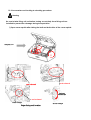
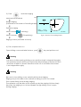
1.3.2 Accessaries and Locking & unlocking procedure
Warning
Be sure to take fixing unit out before turning on certainly since fixing unit are
installed to prevent the damage during transportation
1) Open cover upside after taking the bolts out both sides of the cover upside
fixing unit A~
A~D
red-colored
red-colored
fixing with
adhesive tape
Head Up/
Up/Down Locking A
red-colored
Feeler Locking C
Edger fixing unit location
Head LL-R Locking B
Groove Locking D
*chock any interference with movement
Locking units should always removed with turn off condition.
locking units should always be placed when the transportation is necessary.
improper handling could cause the damage which is not covered underwarrenty.
3)Edger fixing lockerA ,B, C, D is limited.
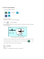
Chapter 2. System components
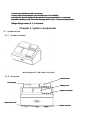
2.1 System Layout
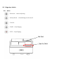
2.1.1 System Overview
Fig. 1
WxLxH (Approx.) : 800 x 430 x 410 (mm)
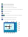
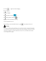
2.1.2 Front view
Control Panel
LCD Display
Sliding Cover
Edger Key Switch
Water Drain Port
Water Inlet Port
* Control Panel : Shows and control all menu
* Edger Key switch : Controls conditions before edging
* Sliding Cover : Shields the noise and filthy water while edging
* Water Inlet Port : Outside nozzle to deliver water while edging
* Water Drain Port : Outlet to release water after edging
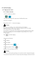
2.1.3 Rear view
Cooling Fan
Power Switch
RSRS-232C
232C
Interface Connector
Barcode
Scanner Connector
Power Connector
Tracer
Connector
Pump1
Pump1 Connector
Blocker
Connector
Fig. 3
* RS-232C Connector : Connector to interface with equipment outside.
* Barcode Scanner Connector : Connector to interface with bar code scanner
2.2 Control Panel
1
2
3
4
5
6
7
8
9
10
11
Fig. 4
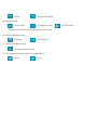
1.
: Lens material --- Choose PLA(Plastic), HPL(High index plastic),
PC(Polycarbonate),GLS(Glass),or ACR(Acrylic resin)
2.
: Frame material --- Choose MTL(Metal), CEL(Celluloid)/ZYL, PNT(two-point),
or NYL(Nylor)
3.
: Edging mode
- 3:7(Auto), 4:6(Auto), 5:5(Auto), CTR(Manual),
EX(EX lens ) are available.
Edging mode
Automated beveling
Controlled beveling
EX lens edging
Rimless(Flat)edging
Automated grooving
Controlled grooving
12
4.
: Use when choose rimless polishing mode.
{(This key is not working in Type GLS(Glass)}
5.
: Use when choose frame switching mode.
6.
: Use when choose the sides of lens or right(R) or left(L)
7.
: Use when choose in setting up the steps of the figures if change edging data.
8.
: Use when choose specific menu.
9.
: Use when move cursors
10.
: Use when regulate the increments and decrements of edging data
11.
: Use when transmit the traced data to screen panel.
12.
: Use when change input shape of designed data
13
14
15
16
17
18
19
V(Vertical)
20
21
H(Horizontal)
MIN : 70.00
22
23
24
25
26
27
28
13. Indicate changed volume of the figures to enter
Use
key and shows by 0.01, 0.1, 0.5(mm)
14. Indicate process steps
Layout Mode : steps to enter edging conditions
Measure process : steps to measure the thickness of lens
Controlled edging ,EX lens edging: Controlled edging,EX lens edging
Rough process : steps to edger roughing wheel
Bevel process : steps to bevel
Finish process : steps to edge delicate
Polish process : steps to polish
Groove process : steps to groove
Chamfer process : steps to chamfer
15. Shows the clamp is locked or not.
: chuck
: unchuck
16. Shows chamfered or not
: no chamferring
:Chamferring
17. Lens materials
: Plastic
: High index plastic
: Glass
: Acrylic resin
18. Frame materials
: Metal
: Celluloid
: Polycarbonate
*Front or Rear
*Both
: Nylon
: two-point (drilled)
19. Edging mode
: Auto mode
: Controlled mode
* (Blank) indicates the flat edging without grooving.
20. Shows polishing mode.
: Polishing
: No polishing
21. Frame changing mode
: Frame changing mode
22. the selected side of a lens to be edged(R/L)
: Right
: Left
: EX lens mode
23. Optical center
DBL
L
PD
FPD
Fig. 6
fig.6
Fig. 7
: Distance between rim center and optical center by the steps of 0.1mm
: Crossing distance from optical center to lens vertically
: Crossing distance from optical center to the bottom of lens vertically
24. FPD (Frame pupil distance) - Pupil distance of glasses frame
DBL (Distance between nasal points) - Distance between nasal points and frame.
(Fig.6,7)
25. PD (Pupillary distance)
(30.00mm~99.50mm by the steps of 0.5mm)
26. SIZE (Size compensation value)
Indicates the compensation value for the complete lens size required from
diameter,which is originated from traced size of the frames or patterns(0.00)
27. Layout mode
: (Optical center)
: (Frame center)
Indicate horizontal and vertical distance between optical center and
frame center
V(Vertical)
H(Horizontal)
MIN : 70.00
: Bi-focal lens mode
27. Memory address(MEM)
Store or read the traced pattern data while use memory function and may be able
to store up to 120 addresses.
2.3 Edger key Switch
2.3.1 Menu
: Retouch -- minor adjusting
: Safety Bevel -- chamferring mode on/off
: CHUCK
: START -- Start Edging
: STOP -- Stop Edging
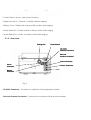
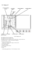
2.4 Edging unit
* Roughing Wheel
(Glass)
* Roughing
Wheel
* Finishing Wheel
* Feelers
* Adaptor * Lens Clamp
(Block Holder)
* Chamfer Wheel * Groove Wheel
Fig.9 Edging unit
*Roughing wheel for glass lens
*Roughing wheel for plastic lens
:Roughing wheel for plastic,poly carbonate, acrylic resin lens
*Finishing wheel : wheel to finish lens edging
* Rimless polishing wheel
: Wheel for polishing the edge of rimless lens
* Chamfering wheel
* Grooving wheel
* Adaptor ( Block Holder )
* Lens clamp
* Feeler
: Measuring apparatus of the thickness of lens
* Polishing Wheel
Chapter 3. The input of edging conditions
3.1. Choose edging conditions
1) Choose lens materials
: Plastic
: High index plastic
: Glass
: Acrylic resin
: Polycarbonate
2) Choose frame materials
: Metal
: Celluloid
: Nylon
: two-point
3) Choose edging mode
: Auto mode
: Controlled mode
4) Choose polishing mode
: Polishing mode
: No polishing
5) Choose edging side
: Right
: Left
6) Choose Chamferring
: no chamferring
: Chamfering both
: EX lens mode
Edging mode
Automatic beveling
Controlled beveling
EX Lens edging
Rilmelss(flat) edging
Automatic grooving
Controlled grooving
3. 2. The input of grinding conditions
MN : 70.00
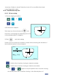
3.2.1.Standard lens
: The vertical distance between optical center and frame center
: The shortest vertical distance from optical center to
outline of lens shape
: The crossing distance from optical center to the lowest point of
the bottom of lens shape
: The crossing distance from optical center to the lowest point of
the bottom of nasal points
3.2.2.Bi-focal lens
':The distance between staright line point downside of lens shape
and center point of distinguished line upside
: The center level height from the lowest point of lens shape
to center level height of distinguished line upside
Chapter 4. Edging
4.1 Standard edging(Beveling)
4.1.1 Automatic edging
1) Choose edging conditions
:
otherwise
:
2) Fix the lens to adaptor
Push leap cup and push
and
fix the lens, as keeping the standard point of leapcup
to the standard point of adaptor.
Standard point
Fig.14 Fixing lens
Note) Edge the lens after keeping the standard points always
,otherwise precise edging may not be able to be made.
Base point
Leap cup
( block)
Standard
Leap cup
Adapter for half-eye
Leap cup for half-eye lens
Base point
3) Push
and start edging
STEP : 0.1
Measure lens thickness
Rough edging
(Switched to the screen of beveling shape)
Delicate edging
When choose (
When choose (
polishing)
Chamfering)
RATIO
3.0 : 7.0
LENGTH(mm) 3.0 : 7.0
Fig.15 Screen of beveling shape
Edging is done( switched to home)
4) Pull complete lens out
Open sliding cover and take the lens , push
MIN : 70.00
key and pull lens out.
Warning
Pull lens out after opening sliding cover and the wheel is stopped throughly.
The operator may be able to be injured by the breakage or broken frictions
when lens is fallen to wheel if take the chuck off on condition that wheel
is not stopped throughly.
Warning
Be sure to close sliding cover certainly before start edging.
Edging may not be able to be worked as sliding cover is not closed.
Don't open sliding cover during edging.
The operator may be able to be injured eye by the edging frictions simply
because the edging is not to be stopped though sliding cover is open
during edging.
4.1.2 Data Controlled Edging
1) Choose edging conditions
:
otherwise
:
2) Fix lens to adaptor
Ref.) Article 2 of 5.1.1. Automatic edging
3) Push
and start edging
Measuring the thickness of lens and switched to simulation screen and system
is to be stopped.
STEP : 0.1
RATIO
3.0 : 7.0
LENGTH(mm) 3.0 : 7.0
Section view posion line
Fig.16 Screen of beveling shape
*The steps on screen indicates the volume of increments,decrements to enter
and may be able to be switched to 0.01, 0.1, 0.5 by pushing
* MIN means minimum sized lens to be edged.
Ratio : Bevel ratio
Scale : "A" thickness
Total : ?
Section "B" : lens thickness ( minimum / maximum )
key
4) Simulate beveled section
: Position line of section viewing is rotated clockwise.
: Position line of section viewing is rotated unclockwise.
Push
or
again to stop the position line of section viewing
Move the postion line of section viewing to the thinnest place of
lens edge and to the thickest place of lens edge in turns by pushing
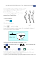
5) Regulate beveling position
Beveling position may be able to be regulated in RATIO
and LENGTH both.
Ex.) Lens Thickness :12mm
RATIO means the rate from lens thickness to
Ratio : 6 : 4
12
beveling position.
6 4
LENGTH means the distance from lens inside
to beveling.
To begin with, confiming the position line of
section viewing , push
and push
or
and activate screen
and then the figures
may be able to be changed.
RATION and LENGTH may be able to be switched
by
RATIO
6.0 : 4.0
LENGTH(mm) 7.2 : 4.8
Fig. 17
Be sure to be careful to use LENGTH function simply because it is only useful for
describe delicate functions ,which RATIO function may not be able to describe.
6) Push
again and start edging.
Rough edging
Delicate edging
Polishing (When choose
Chamfering (When choose
)
)
Edging is done( switched to home)
7) Pull complete lens out
Open sliding cover and take the lens , push
key and pull lens out.
Warning
Pull lens out after opening sliding cover and the wheel is stopped throughly.
The operator may be able to be injured by the breakage or broken frictions
when lens is fallen to wheel if take the chuck off on condition that wheel
is not stopped throughly.
4.2 Optional edging
4.2.1 Edging by the frames
4.2.1.1 Rimless standard
1) Choose edging conditions
:
* No need selecting AUTO mode and CONTROLLED mode.
2) Fix lens to adaptor
Ref.) Article 2 of 5.1.1. Automatic edging
Warning
Be sure to close sliding cover certainly before start edging.
Edging may not be able to be worked as sliding cover is not closed.
Don't open sliding cover during edging.
The operator may be able to be injured eye by the edging frictions simply
because the edging is not to be stopped though sliding cover is open
during edging.
Push
and start edging
Measure lens thickness
Rough edging
Delicate edging
Polishing (When choose
Chamfering (When choose
)
)
Edging is done( switched to home)
Warning
Pull lens out after opening sliding cover and the wheel is stopped throughly.
The operator may be able to be injured by the breakage or broken frictions
when lens is fallen to wheel if take the chuck off on condition that wheel
is not stopped throughly.
* Additional grooving
Grooving may be able to be supplemented additionally for the edged lens of
rimless standard.
However eliminating leap cup from lens or changing R/L or change FPD/PD or
paging data of the other frames may not be worked.
1) Choose edging conditions
:
:
or
2) Fix lens to adaptor
3) Push
and then switched to simulation screen.
4) Check the section out and regulate length or width.
5) Push
and start edging.
4.2.1.2 Grooving
(A) Automatic edging
1) Choose edging conditions
:
:
* Glass edging is not available in grooving.
2) Fix lens to adaptor
Ref.) Article 2 of 5.1.1. Automatic edging
3) Push
and start edging.
Measure lens thickness
STEP : 0.1
Rough edging
(Switched to the screen of beveling shape)
Delicate edging
Polishing (When choose
RATIO
3.0 : 7.0
LENGTH(mm) 3.0 : 7.0
)
MIN : 70.00
Grooving
Chamfering (When choose
)
Edging is done ( switched to home)
Openign sliding cover and seizing lens, push
and pull lens out.
Warning
Pull lens out after opening sliding cover and the wheel is stopped throughly.
The operator may be able to be injured by the breakage or broken frictions
when lens is fallen to wheel if take the chuck off on condition that wheel
is not stopped throughly.
Warning
Be sure to close sliding cover certainly before start edging.
Edging may not be able to be worked as sliding cover is not closed.
Don't open sliding cover during edging.
The operator may be able to be injured eye by the edging frictions simply
because the edging is not to be stopped though sliding cover is open
during edging.
(B) Controlled Edging
1) Choose edging conditions
:
:
2) Fix lens to adaptor
Ref.) Article 2 of 5.1.1. Automatic edging
3) Push
and start edging.
Screen is to be switched to simulation screen after measuring the thickness of
lens and then system is to be stopped.
STEP : 0.1
RATIO
3.0 : 7.0
LENGTH(mm) 3.0 : 7.0
Section view posion line
*The steps on screen indicates the volume of increments,decrements to enter
and may be able to be switched to 0.01, 0.1, 0.5 by pushing
key
* MIN means minimum sized lens to be edged.
* Base ratio is 3:7 under controlled mode.
4) Do simulation of bevel section.
: Position line of section viewing is rotated clockwise.
: Position line of section viewing is rotated unclockwise.
Push
or
again to stop the position line of section viewing.
Move the postion line of section viewing to the thinnest place of
lens edge and to the thickest place of lens edge in turns by pushing
5) Regulate beveling position
Beveling position may be able to be regulated in RATIO
and LENGTH both.
RATIO menas the rate from lens thickness to
beveling position.
LENGTH means the distance from lens inside
to beveling.
To begin with, confiming the position line of
sectional part , push
and push
Ex.) Lens Thickness :12mm
Ratio : 5 : 5
12
5 5
and activate screen
or
and then the figures
may be able to be regulated.
RATIO and LENGTH may be able to be switched
RATIO
5.0 : 5.0
LENGTH(mm) 6.0 : 6.0
Fig. 17
by
Be sure to be careful to use LENGTH function simply because it is only useful for
describe delicate function ,whch RATIO function may not be able to describe.
6) Push
again and start edging.
Roughing
Finishing edging
Polishing (When choose
)
Grooving
Chamfering (When choose
)
Edging is done ( switched to home)
7) Pull complete lens out
Open sliding cover and take the lens , push
key and pull lens out.
Warning
Pull lens out after opening sliding cover and the wheel is stopped throughly.
The operator may be able to be injured by the breakage or broken frictions
when lens is fallen to wheel if take the chuck off on condition that wheel
is not stopped throughly.
4.2.2 Classifications by lens
4.2.2.1 EX lens edging
1) Choose edging conditions
:
or
:
2) Fix the lens to adaptor
Push leap cup forward and push
and
fix the lens, as keeping the standard point of leapcup
to the standard point of adaptor.
3) Push
and start edging
Screen is to be switched to simulation screen after measuring the thickness of
lens and then system is to be stopped.
STEP : 0.1
RATIO
6.0 : 4.0
LENGTH(mm) 6.0 : 4.0
MIN : 70.00
: Position line of section viewing is rotated clockwise.
: Position line of section viewing is rotated unclockwise.
Push
or
again to stop the position line of section viewing
Move the postion line of section viewing to the thinnest place of
lens edge and to the thickest place of lens edge in turns by pushing.
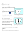
It is not available to get good shape of lens by standard
bevel edging because of level differences between
(A)
near point and far popint like Fig.18 in case of
EX Lens. FIG.17(A)
Therefore it is necessary to regulate the curves
voluntarily like Fig.17 (B),(C) and may be able to
get the curve of desired shape.
(B)
(C)
1) Choose conditions
Choose
2) Fix the lens to adaptor
Fig.17
3) Push
and start edging
Screen is to be switched to simulation scree after measuring the thickness of
lens and then system is to be stopped.
STEP : 0.1
RATIO
6.0 : 4.0
LENGTH(mm) 6.0 : 4.0
Section view posion line
Position section viewing line at the thickest place of lens.
Push
and switch to LENGTH by
and try to regulate with
or
Push
again and try to rotate
or
section viewing line
and check bevel position is off the track from lens.
Section viewing line is supposed to be stopped at the position off the track
automatically if bevel position is off the track.
Try again to get the desired shape by regualting RATIO or LENGTH and do over
again.
Position section viewing line at the thinnest place of lens.
4.2.3 Edging by the functions
4.2.3.1 Frame change edging
This job is worked for using existing lens to new frame.
1) Trace new frame
2) Page new traced data
Traced frame turns up in dotted line at the screen.
3) Push frame change mode
4) The lens by suction cup
4-1) Mark optic center and horizontal
direction with lensmeter.
4-2) Fix lens to leap cup with blocker
MIN : 70.00
Fig.19
5) Trace lens
Refer to 3.6 dummy lens tracing
Traced lens shape turns up in thick line
at the screen.
6) Check lens size is larger enough than frame
out and regulate data in order that lens
and frame may not be crossed.
lens
frame
Ref.
Regulating data are available in PD,SIZE.
Scale change of whole size,size change of left/right,size change of up/down
are available in SIZE.
7) Take lens off from lens setting part and fix lens to edging unit.
8) Edges lens
Ref.
DATA SET key is not working while frame change mode is going on.
4.2.3.2 Safety mode edging
Fast mode is to be switched to safety mode if press
Safety modey may be able to edge more safely.
key for 3 seconds.
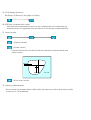
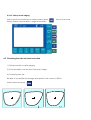
4.3 Checking lens size out and correction
1) Check lens size out after edging.
2) It is requested to correct size if lens size is larger.
3) Correcting lens size
Be able to try versitile size change after position the cursor on SIZE of
main screen and push
( SIZ
( SIZE )
)
(SIZ
)
Chapter 5. Store data and use
5.1 Data store and use
5.1.1 Store data
Push
and transmit traced data to screen.
Position cursor at
Push
, enter address to store by
and store also push
(1~120)
to eliminate data.
5.1.2 Use of data
Position cursor at
Push
, enter address to store by
and transmit traced data to screen.
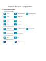
5.1.3 Parameter Setting
Important data change may be able to made at
Refer to MENU hereinafeter specifically.
******** M E N U ********
--> Change Parameter
Regulate Size
Regulate Rotation
Regulate Bevel
Regulate Groove & Chamfer
Regulate Axis
Wheel Dressing & Test
Counter Job
Upgrade Program
Exit
MENU Early screen
Use
to choose functions always.
(1~120)
1) Change Parameter
***** Change Parameter *****
-->
69.00
--> Initial Value of FPD
Initial Value of PD
62.00
Height of Optical Center
2.0
BiF Chuck Layout Hor
5.0
BiF Chuck Layout Ver
5.0
Bevel Polish
Yes
Chamfering Mode
F&R
Barcode Memory
No
Check Cover Sensor
Yes
Text Display
Yes
Rework : Start from grooving
No
Rework : Remove chamfering
No
Tracing Mirror Image
R
Network Address
No
Exit
<--
* Initial Value of FPD : Means FPD value, early assigned
* Initial Value of PD : Means PD value, early assigned
* Height of Optical Center : Means vertical distance between optical center
and frame center
* BiF Chuck Layout Hor : Horizontal distance at near part side from bi-focal lens
* BiF Chuck Layout Ver : Vertical distance at far part side from bi-focal lens
* Bevel Polish : Means bevel polishing is available or not
* Chamfering Mode : Means chamfering is available or not
* Barcode Memory : Means bar code function is working or not
* Check Cover Sensor : May check cover sensor is working and
may not begin edging if chosse YES and cover is open.
* Text Display : Shows text menu.
* Rework : Start from grooving :
If YES, rework begins from grooving and if NO,only last process are repeating.
* Rework : Remove chamfering : Choosing chamfer or not in case rework
2) Regulate Size : Necessary compensation value for regulating lens size
***** Regulate Size ***
--> Finish Size
(PLA
(PC
(GLS
(HPL
(PLA
(PC
(GLS
(HPL
--> Bevel)
--> Bevel)
--> Bevel)
--> Bevel)
---> Flat)
---> Flat)
---> Flat)
---> Flat)
Finish Wheel Size Compensation
Polish Wheel Size Compensation
Minimum lens size for edging
0.00 <-0.00
0.00
0.00
0.00
0.00
0.00
0.00
0.00
0.00
18.90
* Finish Size : Compensate finish edging values per lens materials
* Finish Wheel Size Compensation : Compensate if finish wheel is abraded
* Polish Wheel Size Compensation : Compensate if polish wheel is abraded
* Minimum Lens Size for Grinding
3) Regulate rotation : Necessary compensation value for regulating rotation
***** Regulate rortation *****
Roughing extra rotation
--> Finishing extra rotation
Polishing extra rotation
Grooving extra rotation
Chamfering extra rotation
PC lens extra rotation
Rotation limit
Exit
0
0
0
0
0
0
0
2
<--
*** Fundamentally roughing wheel is to be moved after edging and
but in finish wheel edging the head is to rotated one more and finally
in polishing the edgeing could be completed after 4 more rotations.
* Roughing Extra Rotation : Could add more head rotations
* Finishing Extra Rotation : Could add more head rotations
* Polishing Extra Rotation : Could add more head rotations
* Grooving Extra Rotation : Could add more head rotations
* Chamfering Extra Rotation : Could add more head rotations
* PC Lens Extra Rotation : Could add more head rotations
* Rotation Limit : Edge as much as rotations if edging is not done
4) Regulate Bevel : Necessary compensation values for regulating beveling
***** Regulate Bevel *****
-->
Bevel Height Constant
Bevel Finish Position
Bevel Polish Position
CEL Frame SIZE (H/V)
CEL Frame SIZE (V)
Exit
0.98
0.00
0.00
0.00
0.00
<--
* Bevel Height Constant : Grooving depth of bevel wheel
* Bevel Finish Position : Compensate finished beveling position
* Bevel Polish Position : Compensate finished polishing position
* CEL Frame SIZE (H/V) : Compensate whole size of celluloid frames
* CEL Frame SIZE (V) : Compensate vertical size of celluloid frames
5) Regulate Groove /Chamfer : Necessary compensation value for regulating
beveling/chamfering
***** Regulate Groove & Chamfer *****
Minimum lens width for Groove
Groove Depth
Groove Position
Groove Width
Chamfer Depth
Chamfer Position
<F>
Chamfer Width
<R>
<BVL, F>
<BVL, R>
<FLT, F>
Exit
<FLT, R>
0.40
0.00
0.60
1.50
0.00
0.00
0.00
0.00
0.00
0.00
* Minimum Lens Width for Groove :
* Groove Depth :
* Groove Position : Compensate position of grooving wheel
* Groove Width :
* Groove Compensation Parameter : Compensate depth
* Chamfer Depth :
* Chamfer Position <F>, <R> : Compensate front /rear position
<--
* Chamfer Width <BVL, F>, <BVL, R> : Compensate width
* Chamfer Width <FLT, F>, <FLT, R> :Compensate width
6) Regulate Axis : Necessary compensation value for regulating angle of axis
******* Regulate Axis *******
-->
Groove Wheel Axis Compensation
Chamfer <F> Axis Compensation
Chamfer <R> Axis Compensation
Finish Wheel Axis Compensation
Polish Wheel Axis Compensation
Feeler <F> Axis Compensation
Feeler <R> Axis Compensation
Calibration Axis Compensation
Exit
0 <-0
0
0
0
0
0
-500
* Groove Wheel Axis Compensation :
* Chamfer <F>, <R> Axis Compensation :
* Finish Wheel Axis Compensation :
* Polish Wheel Axis Compensation :
* Feeler <F>, <R> Axis Compensation :
* Calibration Axis Compensation :
7) Wheel Dressing : Whell dressing mode
***** Wheel Dressing & Test *****
-->
-->Water Feed ON/OFF
Wheel Dress ON/OFF
Groove Wheel ON/OFF
Movement Inspection
Exit
<--
* Water Feeding ON/OFF : Confirm pump is working
* Wheel Dressing ON/OFF : Confirm wheel is working
* Groove Wheel ON/OFF : Confirm wheels of groove and chamfer
* Movement Inspection : Contact Sensor Check
gauge encoder values check
head chuck pressure check
①
②
③
④
⑤
How to check
" Movement Inspection" select
"Head Contact Sensor Status --> 0 ON" are turned up and head is going down.
Contact sensor is OK if 4090 off turns up when you lift head up by hands.
Go to next step by pressing "select"
"Arm Contact Sensor Status --> 0 ON" turns up and chamfer wheel is going down.
Head sensor is OK if 4090 off turns up when you lift chamfer wheel down by the hands.
Go to next step by pressing "select"
"Check Encoder Values ---> 0 " turns up and gauge is going down.
Checking the figures by moving gauge to left and right by hands.
It's normal if more than "3000" turns up when moved to the end of left and right.
Go to next step by pressing "select"
"Did you install a Lens? (Yes->[+], No->[-])" turns up and head goes back
to original position.
That's the MODE to check pressure by inserting pressure guage in to the middle
of head.
Pressure differs from what lens are chosen from first MENU.
When press "No->[-]" and moves to MENU mode.
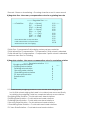
8) Counter Job : Indicate the number of edged lens for each lens material
the number of polished,grooved,chamferd one too
***** Counter Job *****
-->
--> Exit
Glass
Plastic
Polica
Polish
Groove
Chamfer
-->
-->
-->
-->
-->
-->
-->
-->
-->
-->
-->
-->
Total
-->
-->
00000 PCS
00002 PCS
00000 PCS
00002
00000
00000
9) Upgrade Program
***** Upgrade Program *****
--> Exit
Waiting . . .
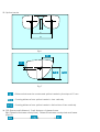
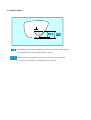
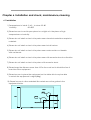
Chapter 6. Installation and check, maintenance,cleaning
6.1 Installation
1) Temperatures to install : 5~40 , to store:-25~80
Humidity
: 50~80%
2) Please be sure to avoid open place to sun light or in the place of high
temperatures or humidity.
3) Please do not install or store in the palce near chemical materials or explosive
materials.
4) Please do not install or store in the place near hot air baloon.
5) Please do not install or store in the place near water and do not handle
with wet hands.
6) Please do not install or store in the place near with excessive shock or vibration.
7) Please do not install or store in the place with excessive dusts.
8) Please keep the distance more than 10Cm from wall not to shield the fan of
rear side of the equipment.
9) Please be sure to place the equipment on the table which may be able
to sustain the equipments' weight(40kg)
10) Please be sure to other materials like metals are not be gotten in the
equipment inside.
Water
Ø80
600
65
Ø100
Water Drain
520
220
170
520
VerVer-02
170
800
6.2 Check
1) Be sure to check the equipment is off certainly before working and after.
2) It is necessary to check the equipment over all every two years.
3) It is necessary to secure enough space for check.
Approx. 500mm
4) It is necessary to use rated fuse.(capacity 6.3A)
If not, not rated fuse could cause fire incidentally.
Make fuse holder free by using small-sized driver and switch fuse and then
put holder back.
Please be sure to turn off power before switching fuse.If not it could cause electric
shock.
5) Appropriate dressing sticks should be used otherwise may be able to give
damage to wheels.
6) Never dress roughing wheel for edging plastic.
May be able to give damage to wheels.
7) It is necessary to change filthy water to clean water not later than 30days.
Filter or water delivery pipes may be able to be stuck.
6.3 Maintence
Caution
1) Unplug if the machine is not working for a long period.
2) Cover tracing unit and edging unit unless the machine is not working to avoid dusts.
Piled dusts may affect the accuracy and cause trouble.
3) Please be sure to do starting check before operation and finishing check after
operation.
4) Please be sure to use appropriate dressing stick for wheel dressing.
If not ,it may cause damage for the wheel and not operate properly.
5) Please be sure to wear protection spectacles to do wheel dressing.
6) Keep enough water storage, 70%~80% of the tank capacity.
7) Replace dirty water with clean water.
8) It is recommended to replace wheels at every two years or after edging
2,500 pairs lenses.It is required to contact the authorized agency
who handle this machine
9) Check tension of belts and make it tight.
10) Replace wheels when it is regarded worned out.
11) Replace water proof seals if the codition of seals are bad.
12) Put more grease on lens clamp axis,lens rotating axis.
13) Replace pipes if the pipe is cracked or stucked.
14) Put the accessories in the designated place not to lose or not to give damage.
15) Check adaptor of outlet is not be stucked with impurities.
6.4 Cleaning
1) Clean pins of power plug with dried fabrics from time to time.
2) Keep local wastes handling regualtions when dispose wastes.
3) Clean edging unit with soft brush and clean water after operation.
Be careful the water is not be soaked or penetrated into machine inside.
4) Take dusts off from the accessories after operation.
5) When outside panels or the surface of machine became dirty ,
clean dirty part with soft fabrics with neutral detergent.
Don't use organic chemistry detergents like solvent at all.
6) Cover the machine well to prevnet from live small-sized animals like rats.
Chapter 7. Safety
Warning
: Means the risk which may cause dead or serious wound
if the operator doesn't care.
Caution
: Means the risk which may cause light injury or financial loss
if the operator doesn't care.
Warning
: Means the risk of electric shock
7.1 Caution while using
Warning
1) Do not touch the wheel absolutely while the equipment is working.
May be able to occur serious injury.
2) Do not open noise-proof cover certainly while the equipment is working.
Sludges edged may give serious hazard on eye.
3) Release chuck after the wheel is stopped throughly.
Sludges edged may give serious hazard if the lens is to be fallen on wheel
and to be broken.
4) Stop the equipment right now if the cracks are found in wheels or lens.
5) Use the equipment only for the edging of lens.
Other uses may cause lowering the performance of the equipment or
got damage by the broken wheels.
Caution
1) Do not dismantle or check it out without consent of experts .
May be able to cause damage by electric shock or breakdown.
2) System is down when abnormal condition is detected , at the same time, error
message is turned up.
Turn off the power switch after confirming the error code.
3) Be careful to decide lens materials.
Wrong choice may break the lens and leesen the use expectancy of the wheels.
4) Be sure to chamfer both sides of lens otherwise it may be able to give
hazards to hands.
5) Do not give excessive power to the stylus of tracing unit.
Stylus may be able to be bent or brocken and cause brakdown.
6) Be sure to fingers not to be held when you fix the lens to chuck.
7) Be sure to use cup remover from VISSLO when you take leapcup
off lens and take the leap cup with soft fabric if take it by naked hands
to avoid hazard against hands.
8) Be sure to the part of the body or other garbages not to be held in the
working part of stylus while tracing.It may cause breakdown.
7.2 Transfer
Caution
1) Be sure to seize the metal part of the equipment bottom certainly
and transfer by more than two persons.
2) Be sure to hands are not stuck between table and the equipment when
put down the equipment.
3) Be sure to transfer after fixing the equipment fixing unit certainly like
before installing.
Shock during transfer may be able to cause breakdown.
4) Be sure to use rated packaging materials to pack and then transfer.
7.3 Wiring
Caution
1) Do not take code wire but plaug itself when take the plug off from power inlet.
Impared code may be able to occur electric leakage or fire.
2) Contact the authorized personnel if the wires are peeled off after turning off.
3) Contact the authorized personnel after turning off if wire becomes too hot.
4) Be careful wires are not bent by heavy materials.
Damages on wire may cause electric leakage or fire.
5) Clean the pins of plug regularly.
Much dusts on the pins may cause electric leakage or fire.
6) Connect cord accurately till pin is fitted into the socket throughly.
Damages on wire may cause electric leakage or fire.
7) Turn off power right now if smells or smokes, sparks or sounds.
8) Do not load much to the one power cord.
Overloading may cause heat and fire.
9) Use suitable rated socket.If not it may cause electric leakage or fire.
10) Be sure to install earth.
If not it may cause electric leakage or fire.
11) Please be sure to keep to use LAN port in the building inside only.
12) If the equipment is used in a manner not specified by the manufacturer,
the protection provided by the equipment may be impaired.
Chapter 8. Error code
This system provide self-analysis functions by watching and checking always.
Abnormal condition is detected,systme is stopped automatically and following
error codes turned up on the screen.
Error code Meanings
10
20
30
40
41
42
50
51
52
55
60
61
74
75
84
Head transfer(left/right) sensors or motor error
Head rotaing axis sensors or motor error
Head transfer(up/down) sensors or motor error
Chamfer load motor or standard sensor error(up)
Chamfer load motor or standard sensor error(down)
Chamfer load motor or standard sensor error(down)
Chamfer load motor or standard sensor error(up)
Chamfer load motor or standard sensor error(down)
Gauge sensor error
Gauge rotating sensor
Chuck motor error(Unchuck)
Chuck motor error(Chuck)
Main head gap sensor error
Main head gap sensor error
Chamfer arm gap sensor error
* Please refer to service manual how to handle the errors specifically.
Chapter 9. Usable environmental conditions
-Indoor use only
-Altitude up to 2000 m
-Operating temperature up to 40 °C
-Maximum relative humidity up to 80°C
-Mains supply voltage fluctuation up +/- 10% of
-The nominal voltage
-Transient over voltage category ∥
-Applicable rated pollution dsgree 2
-Degree of protection IPX0
Chapter 10. Symbol Description