1
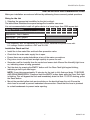
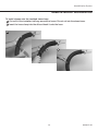
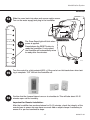
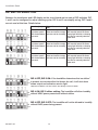
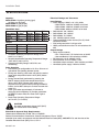
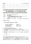
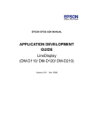
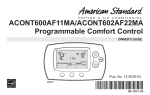
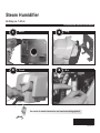
Steam Humidifier
As Easy as 1-2-3-4
PROFESSIONAL INSTALLATION GUIDE
1
Mount
2
Hang
3
Plumb
4
Wire
See inside for detailed instruction and remote mounting options!
69-2307-01
Installation Guide
Table of Contents
Installation Recommendations....................................................... 1
List of tools/supplies....................................................................... 2
Safety Precautions.......................................................................... 3
Duct Mount Instructions
Installation........................................................................................ 4
Remote Mount Instructions
Installation........................................................................................ 6
Plumbing and Wiring
Plumbing.........................................................................................14
Wiring............................................................................................. 15
DIP Switch Selection..................................................................... 18
Troubleshooting............................................................................. 19
Cleaning and Seasonal or Vacation Maintenance....................... 23
Additional Information
Parts List........................................................................................ 26
Need Help?
For assistance with this product please visit Rheem.com or Ruud.com
or call 479-648-4900.
Read and save these instructions.
69-2307—01
ii
Humidification System
Installation Recommendations
Make your installation accurate and efficient by addressing these commonly asked questions:
Sizing for the Job
1. Selecting the appropriate humidifier for the job is critical:
The table below illustrates the square footage the humidifier can serve.
It is not recommended to install a 6 gallon device in a home larger than 2000 square feet.
Square Feet of Space
500
1000 1500 2000 2500 3000
ARI* Recommended Output Delivery (GPD)
0.1
2.2
4.4
6.5
8.6
11.7
RXIH-AS12A - True 12 Gallons
RXIH-AS09A - True 9 Gallons
RXIH-AS06A - True 6 Gallons
*ARI Guideline F-2007 for maintaining 35% RH in a tight, residential four-person home with
8-ft. ceilings. Outdoor conditions = 20ºF and 70% RH.
Installation Check-out List
• Install the in-line water filter and back-flow prevention valve.
• Check that the main water supply line is open.
• Ensure there are no water leaks/drips at any of the water connections.
• Plug into a circuit with at least enough capacity to power the unit.
• Generate a call for humidity from the control and ensure tank fills and the Humidify light turns
on, indicating steam is being generated.
• Test the drain by pressing the EMPTY button until the Clean Tank light begins blinking,
indicating a drain cycle has begun.
NOTE: It may take approximately 10 minutes for the tank to fully flush and drain. TO BYPASS
AND DRAIN IMMEDIATELY, Press and hold the EMPTY button again while the Clean Tank light
is blinking. This will bypass the flush and immediately drain the tank. TO STOP draining, press
the Reset button.
• Mount the provided yellow tank service sticker on the duct/wall near the unit. Ensure the
drain hose is secured to prevent inadvertent disconnection. Check that the hose is plumbed
to a drain/condensate to prevent water spurting.
1
69-2307—01
Installation Guide
Installation Recommendations
Setting Homeowner Expectations for the humidifier Experience:
It may take up to a week of continuous operation to achieve the humidity set point, depending
on weather, size of home, furnishings in the home, insulation, etc.
If using a six (6) gallon unit, the most appropriate setpoint is 30-35% or until there is condensation on the windows, then lower the setpoint. If the home can’t achieve the setpoint, the unit may
be under-sized (if home is under 2000 sq ft, this can also be due to insulation, windows, arid
climate, etc.) or the outdoor temperature may be too low to maintain adequate humidity levels.
Rheem recommends waiting for the temperature to moderate closer to 20°F (-6°C).
If this occurs and the selected humidity levels are not achieved, then a larger capacity model
may be needed.
For the first week of operation, it is normal to experience a slight plastic odor in the home,
depending on the amount of supplied ventilation. If the remote hose is used, there may be a
slight rubber odor. These odors will dissipate within days of installation.
If the homeowner sees the humidifier is not humidifying but there is a call for humidity, it is likely
the unit is operating in drain cycle mode. Ask the homeowner to check again in an hour if they
are concerned the device may not be operating.
If the Call Service light is blinking, instruct the homeowner to press and hold the Reset button to
clear the fault. If the fault doesn’t clear, unplug the power the humidifier and plug back in to the
electrical outlet. Wait 24 hours prior to calling a contractor. The call service light may be blinking
due to a low voltage condition in the area and will reset to operate correctly when full power is
restored.
There may be a slight increase in the homeowner’s energy consumption. However, when operating correctly, the humidifier will make the home feel warmer, allowing the homeowner to lower
the temperature setting on the thermostat. Every degree lower on the thermostat can save up to
3% on heating costs.
69-2307—01
2
Humidification System
What you will need to install the Humidistat
Tools/Hardware needed:
Material Provided:
• Wire stripper/cutter
• 1/4-in. copper or plastic water line
• Drill or duct-cutting tool
• 1/2-in. drain hose and clamps
• 1-3/4-in. hole saw
• Mounting bracket and hardware
• 1/8-in. drill bit
• In-line water filter* (50028044-001)
• Phillips and slotted (or Torx) screwdriver
• Saddle valve
• 18-gauge thermostat wire (5 or 2 conductor)
• Back-flow valve (50030142-001)
Options:
• Remote Installation Kits
– 10-foot hose and nozzle kit (50024917-001)
– 20-foot hose and nozzle kit (50024917-002)
• Humidity Controls
– Manual Humidistat
– Automatic Digital Humidistat
• Water line T-fitting
• Manual shut-off valve
• Remote hose P-trap
• Differential pressure switch (50027910-001)
* Warranty requires in-line water filter installation with regular service.
3
69-2307—01
Installation Guide
Safety Precautions
CAUTION: Voltage Hazard.
Can cause electrical shock or equipment damage.
Disconnect HVAC equipment before beginning installation.
Safety Precautions
• Do not direct the steam nozzle at people.
• If used near a pool or spa, ensure the humidifier can not fall into the water or be splashed.
Also, ensure the humidifier is plugged into a GFI ground fault interrupt outlet.
• Water inside tank can be very hot. Follow installation instructions and service steps exactly
as given in the technical literature.
Warning: Electrocution, Heavy Equipment, and Chemical Hazard.
Can cause death, blindness, water damage to home and heating element failure.
• Do not cut into any air conditioning or electrical line
• Wear safety glasses when cutting or drilling.
• Mount the humidifier in a level position to avoid water damage or heating element failure.
• Reinforce duct as necessary to ensure stability.
The preferred installation location is on the warm or supply side of the furnace. If that location is
not possible, the steam nozzle should be inserted a minimum of 12 in. upstream of the furnace filter.
Depending on the location and the duct rigidity, additional duct reinforcement may be necessary.
Warning: Steam Condensation, Fire, and Freezing Water Hazard.
Can cause failure of fan or limit control or result in water damage to home.
• Do not install the humidifier where the ambient temperature is lower than 32°F (0°C) or higher
than 120°F (49°C).
• Do not install the humidifier through sidewalls of a return air duct made of wood (e.g., floor
joist).
• The mounting area must be strong enough to support the humidifier’s weight when it is full
of water (approximately 12 to 15 lbs.), and to hold the humidifier in a level position for safe,
reliable operation. Otherwise, additional duct or wall reinforcement will be necessary.
• If the ducting has exposed insulated materials on the interior, ensure the nozzle extends
beyond the insulation by clearing away excess insulation at the insertion point. You may wish
to replace a section of insulated duct (approximately 6 in. x 6 in.) with rigid, non-insulated
sheet metal to ensure effective installation.
• Mount the unit where it will have smooth air flow across the end of the steam nozzle.
• Allow at least 1 foot clearance to ventilation holes in humidifier’s cover. Do not cover these
holes. Covering them can increase the internal operating temperature of the humidifier and
shorten the humidifier’s life.
• Allow at least 4 inches of clearance between the steam nozzle insertion hole and the top of
the interior duct to avoid condensation forming. The mounting template is designed to allow
clearance if the top of the template is at or below the top surface of the interior duct.
• Do not mount directly to duct board.
• Do not install in completely enclosed spaces, such as a cabinet or unventilated closet.
Choose a location that is well ventilated.
69-2307—01
4
Humidification System
If installing the humidifier directly to the supply duct, follow steps on pages 5–6 and 14–18.
If mounting remote from the duct, follow steps on pages 7–18.
DUCT mount installation
1
Choose a location that has access to a:
• Drain allowing a slope of 1/4 in.
per foot of drain hose.
• Cold water line.
• Electrical circuit rated to your
humidifier.
• Vertical surface with adequate
clearances.
Model
RXIH-AS06A
RXIH-AS09A
RXIH-AS12A
Continuous
downslope
Draining water
may be hot.
Ensure drain outlet not exposed.
Required Minimum
Circuit Capacity
7 Amps
10 Amps
12 Amps
M24745
CAUTION
Hot water temperature above 120°F (49°C)
can cause burns from scalding.
M24744
2
Install duct nozzle.
Ensure o-ring gasket
is properly seated in
the groove.
M24894
Insert nozzle and twist clockwise to ensure tight seal of
nozzle to the humidifier.
M24746
5
69-2307—01
Installation Guide
DUCT mount installation
3
Position template sticker on supply duct. For tall coils that do not have this
clearance available, refer to remote mounting instructions.
SUPPLY
4
Drill 1-3/4-in. hole.
12 INCHES
M24748
5
Secure bracket to duct using #8
self-drilling sheet metal screws (4).
6
A) Slide foam gasket over nozzle and
insert the nozzle into duct hole
(pictured).
B)Push down to secure humidifier to
bracket arms. Ensure gasket forms
tight seal in duct hole.
Allow 3 in. clearance from nozzle
outlet to duct wall.
B
A
M24749
Foam
gasket
M24750
Proceed to page 14 for plumbing and wiring instructions.
69-2307—01
6
Humidification System
Remote mount installation
Use for mounting to a location other than the supply duct.
Most operation problems are caused
by improper hose installation. Always
ensure an uphill flow when installing
the remote hose, and avoid kinks,
sharp turns, or low spots that could
restrict the flow of steam into the
injection nozzle or condensation back
into the humidifier.
If the remote hose cannot be installed
with an upward pitch of 2 in./ft., a
wetted drip tee must be installed.
Failure to do so can result in back
pressure on the humidifier, which can
lead to duct nozzle water spitting or
leaking gasket. Remote hose must be
supported to prevent sagging or low
spots.
1
When remote mounting, also follow these critical
steps in sizing the proper humidifier:
The 6-gallon model can be remotely mounted up to
15 feet if insulating the steam distribution tube
The 9- and 12-gallon models can be remotely mounted up to 20 feet.
Ensure at least 2 in. per foot slope if installing the
remote hose horizontally.
Choose a location for the humidifier and the
remote duct nozzle (see remote installs on
page 8).
It should have access for:
• Remote hose installation. Steam hose
must be installed with 2 in./ft. pitch on a
continuous uphill slope.
Maximum 3 ft.
2 in./ft. uphill
• Drain. Allow a continuous downslope to the
drain.
6 in.
• Cold water line.
8 in.
• Electrical circuit rated to your humidifier
(see circuit ratings on page 10).
1/2 in.
minimum
diameter
M24896A
Funnel or floor drain. Refer to governing
codes for drain pipe size and maximum
temperature requirements.
7
Water in
elbow
69-2307—01
Installation Guide
Proper Hose Installs
Furnace or Mechanical Room Remote
Note: If air handler location temperatures will drop
below freezing at any time, the humidifier must be
mounted in a conditioned space, running a remote
hose to the duct.
Duct Mount Remote
M24781
CAUTION
Hot water temperature above 120°F (49°C)
can cause burns from scalding.
M24936
Garage Remote
Living Area Remote Options
M24786
M24785
69-2307—01
8
Draining
water may
be hot.
Ensure
drain outlet not
exposed.
Humidification System
PRoPeR hose InsTalls
20 FT MAX
WITH TRAP
2 IN. PER FT
5 FT MAX
IF NO SLOPE
3 FT MAXIMUM
P - TRAP
DRAIN
TYPICAL INSTALLATION
WHEN HUMIDIFIER IS ABOVE
REMOTE NOZZLE
20 FT MAX
10 FT MAX
GENTLE BEND
2 IN. PER FT
DRAIN
P - TRAP
2 IN. PER FT
2 IN. PER FT
OBSTRUCTION
SUPPORTED REMOTE HOSE
DRAIN
WETTED P - TRAP
NOTE: HEIGHT OF TRAP MUST BE GREATER
THAN THE DUCT STATIC PRESSURE
NOTES:
• Minimumupwardslopeofhoseindirectionofsteamflowat2in.perfoot;
• Minimumdownwardslopeofhoseindirectionofsteamflowat3/4in.perfoot;
• Maximumlengthofremotesteamhoseis20ft.
• HeightofP-trapsmustbegreaterthantheductstaticpressure.(Typical3in.
will suffice.) P-trap must also be wetted (see page 7).
• Minimizesharpbendsandelbows.
AVOIDTHESEINSTALLATIONMISTAKES.
SAG
NO SLOPE
NO SLOPE
KINKED
UNDRAINED
ELBOW
M29028
9
69-2307—01
Installation Guide
Remote mount installation
Model
RXIH-AS06A
RXIH-AS09A
RXIH-AS12A
Minimum Circuit Capacity
7 Amps
10 Amps
12 Amps
M24745
2
Draining water
may be hot.
Ensure drain outlet not exposed.
Install hose adapter from Remote
Mount Kit.
Ensure o-ring gasket is
properly seated in the
groove.
Continuous
downflow
M24744
CAUTION
Hot water temperature above 120°F (49°C)
can cause burns from scalding.
Remote Mount Kit
(sold separately)
M24764
Hose Adapter
Hose Clamps
Duct Nozzle
Remote Hose
M24765
• 50024917-001 = Ten Foot Insulated Hose Kit
• 50024917-002 = Twenty Foot Insulated Hose Kit
M24894
Insert hose adapter and twist
clockwise to ensure tight seal
of nozzle to the humidifier.
69-2307—01
10
Humidification System
Remote mount installation
Position template sticker on remote location.
Note: The humidifier will weigh 12–15 lbs. (+/- 2 lbs.)
with water, so if mounting onto drywall or plaster,
position one side over a wall stud.
3
M24766
4
Insert wall anchors (4) into pilot holes and secure
bracket to location.
5
M24767A
Push down to secure the humidifier
to bracket arms.
M24768
11
69-2307—01
Installation Guide
Remote mount installation
6
Cut a 1-3/4 in. diameter duct hole, install the provided
gasket, and slide the remote nozzle up into the duct.
Secure remote nozzle to duct using #8 self-drilling
sheet metal screws (4).
7
Run remote hose from
the humidifier to the duct
nozzle location. Up to 20
ft. of hose can be used.
Minimum 3 in. clearance
required from nozzle outlet to
duct wall.
M24770
If mounting remotely requires running
hose through structural barriers (ie.
wall or ceiling), cut at least a 2-1/8 in.
hole and slide hose through.
8
Seal off unconditioned space with a
grommet (not provided) or caulk.
9
Attach remote hose by sliding over the nozzle
and adapter. Secure both hose ends with
clamps (provided).
M24771
69-2307—01
IMPORTANT:
Run hose continuously uphill. For horizontal runs,
ensure a slope of 2 in. uphill per foot. Secure hose
every horizontal foot using clamps (provided).
For long horizontal runs, support the hose by first
securing a length of 2 x 4 lumber, U-channel, or
angle iron with the appropriate slope. Then attach
the hose to the top of this support. If remote hose
requires downward pitch, refer to pages 7 and 9 for
instruction.
12
Humidification System
Remote mount installation
To install clamps onto the insulated steam hose:
A Cut a slit in the insulation half way around the house. Do not cut into the steam hose.
B Insert the hose clamp into the slit and hook it onto the hose.
A
B
13
69-2307—01
Installation Guide
Plumbing
10
A
Insert 1/4-in. water line into filter. Apply modest pressure to ensure a tight fit.
B
Insert 1/4-in. water line into back-flow valve. Apply modest pressure for a tight fit.
C
Connect 1/2-in. drain tube. Secure drain tube to barbed fitting with hose clamp.
D
Shut off the water supply. Secure 1/4-in. copper or plastic water feed tube.
Description
In-Line Water Filter (included)
(required for warranty)
Back-flow valve (included)
(required)
Part Number
50028044-001
50030142-001
To water supply
B
A
1/4-in. copper
or plastic
Enlarged view
Continuous
downslope
Draining water may be
hot. Ensure drain outlet
not exposed. Ensure
drain or condensate
pump is rated for at
least 120°F water.
C
1/2-in.
drain tube
D
M27428
1/4-in. water line
M24772
CAUTION
Hot water temperature above 120°F (49°C)
can cause burns from scalding.
Water line tapping options. See instructions provided with the option you choose.
T-fitting
Saddle valve (provided)
To humidifier
Piercing pin
Manual shutoff
valve (sold
separately)
M24852
To humidifier
Water supply line
Check all water line connections to ensure no leaks once the humidifier is operational.
69-2307—01
14
Humidification System
wiring
11
Loosen captive cover
screw. Slide cover out from
front.
CAUTION: Voltage Hazard.
Before wiring to HVAC terminals, disconnect HVAC
equipment power. Ensure humidifier is not plugged in.
M24754
Low-Voltage Terminals
24V
AC power for electronic humidistat.
HUM Low-voltage humidistat (or thermostat) terminals control
humidifier operation.
24V
24V
HUM
HUM
C
GT
R
RT
GF
EXT
C, R
Connects to HVAC system transformer terminals (or relay
transformer fan control R and C) to ensure HVAC power
is present before humidifying. This can be disabled by
changing DIP switch 4 (see page 18).
RT
Connects to thermostat R terminal, which is normally
switched to call for fan.
GT,
GF
GT connects to thermostat G terminal. GF connects
to fan board G terminal. Thermostat G passes through
the normally-closed (NC) relay contacts to GF, allowing
fan activation. When the humidifier is ready to provide
humidity to the home, it will take control of the fan by
forcing power from RT to GF (if not already activated).
EXT
When a 24-vac fan board is not used to control blower
(hydronic or cooling-only applications), this connection
with GF provides dry-contact closure for fan calls. EXT/
GF may be wired to a low-voltage relay control center to
provide line-voltage fan control.
M24895
Route wires through the raised harness tabs and out the notch at
the rear of the chassis. Ensure wires are secure and do not interfere with assembly of cover.
M24893
Tabs
Notch
15
69-2307—01
Installation Guide
wiring
Wire the humidifier according to the diagram that applies to your humidity
control.
12
Follow this diagram if using a mechanical
humidistat.
Follow this diagram to wire Automatic Digital
Humidistat for manual operation.
MECHANICAL
HUMIDISTAT
HVAC
Set the digital humidistat ISU parameter 10 to 1, and
ISU 25 to 2.
For auto-operation: also wire W and G to thermostat
B
DIGITAL HUMIDISTAT
W and G.
B
HVAC
A
HUM
HUM
R
C
W
Y
G
RECOMMENDED
AIR FLOW
SWITCH (AFS)
24V
24V
HUM
A
HUM
HVAC
POWER
MASTER
R
C
W
Y
G
HUM
HUM
R
C
C
24V
GT
RECOMMENDED
AIR FLOW
SWITCH (AFS)
R
RT
24V
HUM
GF
HUM
EXT
C
HVAC
POWER
MASTER
GT
R
Rc
W
Y
G
Factory
installed
jumper
R
HUMIDIFIER - INTERNAL
RT
GF
EXT
R
THERMOSTAT
If AFS is used, ensure
DIP 5 is in ON position.
Rc
W
Y
G
M29029
HUMIDIFIER - INTERNAL
Factory
installed
jumper
M29030
THERMOSTAT
If AFS is used, ensure DIP 5 is in ON position.
Follow this diagram if using a blower fan dedicated to the humidifier (a fan separate from the HVAC
equipment, as in hydronic or cooling-only applications).
120 VAC
24V
HVAC
R
24V
RECOMMENDED
AIR FLOW SWITCH
(AFS)
C
RELAY
RED
HUM
HUM
L1
C
120
VAC
GT
HVAC POWER MASTER
R
RT
L2
GF
EXT
HUMIDIFIER - INTERNAL
BLACK
AT120
MECHANICAL
HUMIDISTAT
If AFS is used, ensure DIP 5
is in ON position.
Remove Factory
installed jumper
(R/RT)
HUMIDISTAT
HUM
HUM
HUM
HUM
HAC
HAC
HAC
HAC
M29031
69-2307—01
16
Humidification System
Wiring
13
Slide the cover back into place and secure captive screw.
Turn on the water supply and plug in the humidifier.
POWER
HUMIDIFYING
CLEAN TANK
SEE LABEL BELOW !
14
CALL SERVICE
PRESS RESET
The Press Reset light will blink when
power is applied.
Press/release the RESET button to
ready the humidifier. If not pushed,
the humidifier will automatically move
to ready after five minutes.
PRESS EMPTY
RESET
M24762
EMPTY
M24763
15
16
Turn the control to a high setpoint (60% +). Be sure to turn this back down when testing is complete. “Off” will turn the humidifier off.
Confirm that the furnace blower turns on to circulate air. This will take about 10–15
minutes upon call for humidity.
Important for Remote Installation:
After the humidifier has produced steam for 10–15 minutes, check the integrity of the
remote hose to ensure no sags have occurred. Add or adjust clamps if necessary to
ensure 2 in. per foot continuous slope.
17
69-2307—01
Installation Guide
dIP sWITCH sELECTION
Between the transformer and LED display on the circuit board are two sets of DIP switches. DIP
1 and 2 can be configured to adjust cleaning cycles. DIP 4 and 5 can simplify wiring. DIP 3 and 6
are not used at this time. Details below.
Run time (hrs)
DIP 6
DIP 5
DIP 4
DIP 3
DIP 2
DIP 1
ON
End-of-Season timer
(hrs)
10 hrs of humidify- 48 hrs before system autoing before system drains and remains empty
auto-flushes debris until next call for humidity.
from tank.
Clean tank indicator
20 hrs of humidify- 48 hrs before system autoing before system drains and remains empty
auto-flushes debris until next call for humidity.
from tank.
1 year of total time (operational
and inactive) before the Press
Empty light will blink, indicating
it is time to manually clean the
water tank.
30 hrs of humidify- 48 hrs before system autoing before system drains and remains empty
auto-flushes debris until next call for humidity.
from tank.
1 year of total time (operational
and inactive) before the Press
Empty light will blink, indicating
it is time to manually clean the
water tank.
OFF
DIP 6
DIP 5
DIP 4
DIP 3
DIP 2
DIP 1
ON
OFF
DIP 6
DIP 5
DIP 4
DIP 3
DIP 2
DIP 1
ON
OFF
1 year of total time (operational
and inactive) before the Press
Empty light will blink, indicating
it is time to manually clean the
water tank.
M24853
DIP 6
DIP 5
DIP 4
DIP 3
DIP 2
DIP 1
ON
OFF
DIP 4 OFF, DIP 5 ON: If the humidifier determines that no airflow*
is present two minutes after the blower fan call, it will shut down
steam output and activate a service light.
DIP 6
DIP 5
DIP 4
DIP 3
DIP 2
DIP 1
*Requires installation of air flow switch. See 'Wiring' section for details.
ON
OFF
DIP 6
DIP 5
DIP 4
DIP 3
DIP 2
DIP 1
ON
DIP 4 ON, DIP 5 either setting: The humidifier will allow humidity
without HVAC power present and without airflow.
DIP 4 OFF, DIP 5 OFF: The humidifier will not be allowed to humidify
without HVAC power being present.
OFF
M28181
69-2307—01
18
Humidification System
Troubleshooting
The humidifier has internal system diagnostics that monitor system operation, maintenance schedules, and faults. If a system fault is detected, the system will attempt to recover itself up to five
times in a 24 hour period. If unable to recover in that time, the red Call Service LED light will activate.
If the humidifier Call Service light is red, a system fault has occurred from which the humidifier
can not recover by itself. The table below shows the possible faults, along with steps to fix the
humidifier.
If the red Call Service LED light is on, press/release the RESET button. The red Call Service LED
light will begin blinking in a series that indicates what fault occurred. Refer to the table below
for the fault signified by the number of blinks that occur. To clear the fault, press and hold the
RESET button for 5 seconds.
Press/hold the EMPTY button to clear the Service Timer light (i.e. the Press Empty button).
Press/release the EMPTY button to drain the tank.
No. of
Red
Light
Blinks
1
2
A
3
Fault Description
AutoRecoverable?
Water/Heater temper- Yes, system will
ature sensor failed.
return to “Ready”
if fault no longer
exists in 1 hour.
Steps to Fix
To be Performed by Professional HVAC Technician Only
Unplug the humidifier and remove cover.
Check water sensor connection to electronic board.
Reattach cover and plug the humidifier in.
If fault reappears, follow the cleaning steps on pages 23–25.
Reassemble tank and press the RESET button.
If fault returns, replace with applicable wattage heating
element.
Water sensors failed. Yes, system will
• Unplug the humidifier and remove cover.
return to “Ready” •
Disconnect water level sensor wiring, remove screen and
if fault no longer
lift snap-hinge clamp.
B
exists in 1 hour.
Remove water sensor assembly.
Will attempt to
•Clean water sensor probes using warm soapy water so that
reset itself 5 times
the metal is exposed.
in 24 hours.
•Reassemble the sensor assembly in the unit, reattach and
secure cover.
•Plug unit back in and press the RESET button.
•If fault reappears, replace sensor assembly.
M24901
Failure to fill tank
with water.
Yes, system will
return to “Ready”
if fault no longer
exists in 1 hour.
•
•
•
•
•
•
•Ensure inlet water is on.
•Check for leaks around the tank seal and solenoid.
•Turn off water supply and replace in-line water filter.
•Press/hold RESET button until the red Call Service light
turns off.
•If tank still fails to fill, press the EMPTY button (if unit fails to
drain, unplug unit and make sure water in tank is cool).
• Follow tank cleaning instructions on page 23. Ensure you
have a firm grip of the tank prior to releasing the tank,
especially if water is present.
• Clear any excess debris from the tank’s bottom orifice to the
solenoid.
• Reassemble tank and plug unit back in. Press the RESET
button.
• If water still fails to flush into the tank, replace the solenoid
valve.
19
69-2307—01
Installation Guide
Troubleshooting
No. of
Red
Light
Blinks
4
5
6
7
Fault Description
AutoRecoverable?
Heating element
overheated.
No
Steps to Fix
To be Performed by Professional HVAC Technician Only
• Follow tank cleaning steps (pages 23–25).
• Reassemble tank and press the RESET button.
• If fault returns, replace with applicable humidifier.
Input voltage insuf- Yes, system will
•Unplug and replug the unit in to see if the fault returns.
ficient.
return to “Ready” •If fault returns, unplug unit and remove cover.
if fault no longer
•Ensure wiring connections are secure and attached.
exists in 1 hour.
• If fault returns, replace the humidifier with a new one (field
service is not recommended in the event line voltage is lost).
Water overflow
Yes, system will
•Ensure drain hose is not kinked or submerged in water at
sensed.
return to “Ready”
the drain. Check functionality of condensate pump if used.
if fault no longer • Check for water coming out of drain/overflow line. If
exists in 1 hour.
continuous water flow is present, follow the cleaning steps
on pages 23–25.
• Press EMPTY button to drain tank.
• Set humidistat RH setpoint to Test mode.
• If fault returns, unplug the humidifier.
• Loosen cover screw and remove cover.
• Disconnect water level sensor wiring and lift snap-hinge clamp
to remove water sensor assembly. See image on page 19.
• Clean probes using warm soapy water so that the metal is
exposed.
• Reassemble the sensor assembly in the unit, reattach and
secure cover.
• Plug unit in, and press RESET button.
• If fault reappears, replace water sensor assembly and/or
solenoid valve.
HVAC power not
Yes, system will
•Unplug and replug the unit in to see if power returns.
present (monitor this return to “Ready” •If not, ensure HVAC equipment has power. Check circuit
fault only when DIP 4 if fault no longer
breaker and replace fuse if circuit is tripped.
and 5 are OFF).
exists in 1 hour.
• Unplug the humidifier and remove cover.
• Ensure DIP 4 is ON and reattach cover.
• Plug unit in.
• If fault reappears, ensure the circuit being used has the
rating to support the unit. Unplug any additional equipment
plugged into this circuit. If fault disappears, the circuit
capacity is not properly sized to your unit.
• If fault returns, replace unit.
69-2307—01
20
Humidification System
Troubleshooting
No. of
Red
Light
Blinks
8–11
12
Fault Description
AutoRecoverable?
The backup weld
monitor input is active
when the backup
heater relay is off.
Temperature of the
electronic circuit
board is too high.
No
13
Tank failed to drain.
14
Heater failed to boil
water.
15
No Airflow.
Steps to Fix
To be Performed by Professional HVAC Technician Only
•Replace the unit.
Yes, system will
•Ensure ventilation holes in the cover are clear of
return to “Ready”
obstruction, and that 1 foot of clearance is maintained
if fault no longer
around the cover’s vent holes.
exists in 1 hour.
• Ensure the humidifier is installed in a location with
conditioned air 32°F (0°C) to 104°F (40°C).
• Turn humidistat off and allow time for electronic board to cool.
• Turn humidistat on and press RESET button.
• Confirm humidity call starts by HUMIDIFYING light turning on.
• Allow unit to run and check for steam leaks around tank and
ventilation holes.
• If steam is present, replace the humidifier.
No
•Water in tank may be hot (>140ºF [60ºC]).
•Press the EMPTY button.
•If unit fails to drain, wait for water in tank to cool. Ensure
tank water is cool before proceeding.
• Once cool, follow tank cleaning steps (pages 23–25).
• Reassemble tank and press the RESET button.
• If fault persists, replace the solenoid valve.
Yes, system will
• Follow tank cleaning steps (pages 23–25).
return to “Ready” • Reassemble tank and press the RESET button.
if fault no longer • If fault returns, replace the heating element with the
exists in 1 hour.
applicable wattage replacement part.
Yes
•Ensure Differential Pressure Switch is installed and wired
correctly. See the Wiring section for proper wiring.
•Ensure DIP switches are set correctly.
•If fault persists, replace AFS and/or unit.
21
69-2307—01
Installation Guide
Specifications
Capacity:
RXIH-AS12A: 12 gallons per day (gpd)
(45 liters per day [lpd])
RXIH-AS09A: 9 gpd (34 lpd)
RXIH-AS06A: 6 gpd (23 lpd)
Electrical Ratings and Tolerances
Input Ratings
• Power Supply: 120VAC +10/ -15%, 60Hz
- RXIH-AS12A: 1440W at 120VAC at full load
- RXIH-AS09A: 1200W at 120VAC at full load
- RXIH-AS06A: 840W at 120VAC at full load
• RXIH-AS12A: 12A, 120VAC
• RXIH-AS09A: 10A, 120VAC
• RXIH-AS06A: 7A, 120VAC
• 15A, 120VAC interlock switch
• Thermostat/HVAC power monitor (R to C): 10mA
resistive at 24VAC
• Field wiring terminals: 18–22 ga. solid
• HVAC power/airflow monitor: 10 mA resistive at 24
VAC
Humidified Area:
House
Description
Loose
Average
Tight
Weight:
Air Changes
Per Hour
Two
One
One-half
RXIHAS12A
2000 ft2
2500 ft2
3000+ ft2
RXIHAS09A
1300 ft2
1800 ft2
2500 ft2
RXIHAS06A
1000 ft2
1500 ft2
2000 ft2
Model
Empty
Filled with Water
RXIH-AS12A 9 lbs.
15 lbs.
RXIH-AS09A 9 lbs.
14.5 lbs.
RXIH-AS06A 8 lbs.
12 lbs.
• Dimensions: 11-1/4 in. W x 19 in. H x 9 in. D
• Humidifier Operating Temperature Range: 34ºF–
120ºF (1.1ºC–49ºC)
• Remote Hose/Nozzle Operating Temperature Range:
-50ºF–250ºF (-46ºC–121ºC)
• Operating Humidity Range: 0–95% RH, noncondensing
Output Ratings
• Relay output contacts:
- Fan: 1.5A full load, 7.5A locked rotor at 24VAC
- Heat and Backup: 15A resistive at 120VAC
• Fill Solenoid: 0.1A at 120VAC, 0.5 PF
• Drain Solenoid: 0.1A at 120VAC, 0.5PF
• Humidistat output contacts: 10mA resistive at 24VAC
• Humidistat power supply: 100mA at 24VAC
Drain Operation
• Auto flushing is configurable to 10, 20 or 30 hours of
operational time (heating element active).
• During auto flushing, cold water will enter the tank to
lower water temperature below 140ºF (60ºC) before
draining.
• During manual flush (performed by pressing the
EMPTY button) initial water temperature may be
above 140ºF (60ºC). Ensure drain outlet is not
exposed and use caution when pressing the EMPTY
button, and do NOT attempt to remove the tank with
water in it.
• Flush cycle takes approximately 15 minutes to
empty the tank completely. To override, press/hold
the EMPTY button while the “Clean Tank” light is
blinking.
• Drain Hose Operating Temperature Range:
34ºF–212ºF (1.1ºC–100ºC)
CAUTION
Hot water temperature above 140°F (60°C)
can cause burns from scalding.
Standards & Approval Body Requirements
Underwriters Laboratories: UL998, File no. E185662.
Federal Communications Commission: Class B compliance, File no. YU555.
Intended to be used in accordance with the National Electrical Code (NEC), ANSI/NFPA 70, and the rules of the
Canadian Electrical Code (CEC), Part 1, C22.1.
69-2307—01
22
Humidification System
Cleaning and Seasonal or Vacation Maintenance
Maintenance is simple with the humidistat—just remove the water tank for cleaning.
Warning: Scalding hazard.
Do not attempt to remove the humidifier from the mounting bracket during operation,
or when the humidifier’s water tank when full of water. Water heater could be hot when
tank is removed. Failure to comply could result in severe scalding or death.
Drain Operation
• Auto flushing is configurable to 10, 20 or 30 hours of operational time (heating element
active).
• During auto flushing, cold water will enter the tank to lower water temperature below 140°F
(60°C) before draining.
• During manual flush (performed by pressing the EMPTY button) initial water temperature may
be above 140°F (60°C). Ensure drain outlet is not exposed and use caution when pressing the
EMPTY button, and do NOT attempt to remove the tank with water in it.
To clean the humidifier:
1. Press and hold the EMPTY button for 3 seconds. Wait for the CLEAN TANK light to be
on solid (not blinking). The flush cycle takes approximately 15 minutes to empty the tank
completely. To override the flush cycle press/hold the EMPTY button a second time for 3
seconds. The tank will drain immediately.
Wait
Go to Step 2
CLEAN TANK
(BLINKING LIGHT)
CLEAN TANK
(ON SOLID)
EMPTY
M24776
M24775
M24774
23
69-2307—01
Installation Guide
Cleaning and Seasonal or Vacation Maintenance
3. Grip the white water valve arm and slide it
back within the bracket to disengage from
the tank.
2. Turn the manual shut-off valve at the
bottom of the tank to the “Unlock”
position.
M24777
M24779
4. Firmly grip the tank bottom. Push down
the cover's safety button and pull the latch
forward to release the tank.
Note: Latch does not come off humidifier
with tank.
5. Use tap water to flush loose minerals from
the tank. Sediment screen at tank's bottom
is removable. For a more thorough cleaning,
soak tank in warm, soapy water, then rinse
clean. Tank is also dishwasher-safe.
Sediment screen
M24856
M24778
6. Carefully rub minerals off of the heating
element, reservoir walls, and sensors. Scouring
pads suitable for non-stick pots or pans are
suitable for cleaning the humidifier reservoir
walls and components within the tank.
M24857
69-2307—01
24
Humidification System
Cleaning and Seasonal or Vacation Maintenance
7. Replace inline filter once per year. Turn water supply off before replacing.
Press down filter collar ring and pull
out 1/4 in. water line from each side.
Insert 1/4 in. lines into new filter. Apply
modest pressure to ensure a tight fit.
M27410
M27411
Once clean, reattach tank by securing the latch. Engage the water valve to the cam shaft, and
“Lock” the shut-off valve. The “Press Reset” light will blink at start-up. Push the RESET button
to ready the humidifier.
Automatic End of Season Shutdown
Your humidifier has the built-in intelligence to shut down when humidity is not needed for an
extended period. After 48 hours of inactivity, the humidifier will drain and remain empty until
humidity is needed again. This prevents water from stagnating within the tank. The tank will refill
with water upon next humidity call.
There are a few house-cleaning steps to follow to keep your humidifier operating at peak efficiency:
1. Follow steps 1–6 in the Cleaning section on pages 23–24 at least once per year, or when the
“Press Empty” light is blinking.
2. Clear ventilation holes in the humidifier’s cover.
3. Clear the water drain tube.
4. Make sure the water tank gasket seal is not cracked or split before reattaching the humidifier
water tank.
5. Check that the humidifier is still mounted level.
Extended Vacation
When you leave on extended vacations, it is recommended you turn off the humidifier’s water
supply and turn off the humidity control. When you return, turn on the humidifier water supply
and reset your humidity control to a comfortable position.
25
69-2307—01
Parts List
Part
10-foot Remote Hose and Nozzle Kit
20-foot Remote Hose and Nozzle Kit
Duct Nozzle
Remote Nozzles
Mounting Bracket
Solenoid Valve
In-Line Water Filter
RXIH-AS12A/RXIH-AS09A Water Tank
RXIH-AS06A Water Tank
Water Level Sensor Assembly
Saddle Valve
Back-flow Water Valve
Differential Pressure Switch
Part Number
50024917-001
50024917-002
50028003-001
50028001-001
50020012-001
50027997-001
50028044-001
50033181-001
50033182-001
50027998-001
32001616-001
50030142-001
50027910-001
Fig. Reference
1
1
3
4
5
6
7
8
9
10
11
12
13
1
3
13
4
12
11
8
10
5
7
9
6
M28606
Warranty Information
5 years from date of purchase (contact the Rheem Parts Distribution Center for more
information).
Before proceeding with installation,
refer to installation instructions
packaged with each model, as well
as complying with all Federal, State,
Provincial, and Local codes.
RHEEM
AIR CONDITIONING
DIVISION
5600 Old Greenwood Road, Fort Smith, Arkansas 72908
“In keeping with its policy of continuous progress and product improvements, Rheem reserves the right to make changes without notice.”
® U.S. Registered Trademark.
© 2008
69-2307—01 M.S. 12-08
Printed in U.S.A. on recycled
paper containing at least 10%
post-consumer paper fibers.