1
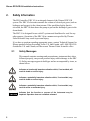
Dionex RFIC-ER Startup Kit Installation Instructions Document No. 065208 Revision 04 October 2012 © 2012 by Thermo Fisher Scientific Inc. All rights reserved. Chromeleon, IonPac, and SRS are registered trademarks of Thermo Fisher Scientific Inc. in the United States. Microsoft and Windows are registered trademarks of Microsoft Corporation in the United States and other countries. Velcro is a registered trademark of Velcro Industries B.V. in the United States and possibly other countries. PEEK is a trademark of Victrex PLC. All other trademarks are the property of Thermo Fisher Scientific and its subsidiaries. Thermo Fisher Scientific Inc. provides this document to its customers with a product purchase to use in the product operation. This document is copyright protected and any reproduction of the whole or any part of this document is strictly prohibited, except with the written authorization of Thermo Fisher Scientific Inc. The contents of this document are subject to change without notice. All technical information in this document is for reference purposes only. System configurations and specifications in this document supersede all previous information received by the purchaser. Thermo Fisher Scientific Inc. makes no representations that this document is complete, accurate or error-free and assumes no responsibility and will not be liable for any errors, omissions, damage or loss that might result from any use of this document, even if the information in the document is followed properly. This document is not part of any sales contract between Thermo Fisher Scientific Inc. and a purchaser. This document shall in no way govern or modify any Terms and Conditions of Sale, which Terms and Conditions of Sale shall govern all conflicting information between the two documents. Revision history: Revision 01 released February 2008 Revision 02 released March 2008 Revision 03 released January 2012 Revision 04 released October 2012 For Research Use Only. Not for use in diagnostic procedures. Contents Dionex RFIC-ER Startup Kit Installation Instructions 1. Introduction . . . . . . . . . . . . . . . . . . . . . . . . . . . . . . . . . . . . . . . . . . . . . . . 1 2. Safety Information . . . . . . . . . . . . . . . . . . . . . . . . . . . . . . . . . . . . . . . . . . 2 2.1 Safety Messages . . . . . . . . . . . . . . . . . . . . . . . . . . . . . . . . . . . . . 2 2.2 ERC 10 Labels . . . . . . . . . . . . . . . . . . . . . . . . . . . . . . . . . . . . . . 4 2.3 ERC 10 Specifications . . . . . . . . . . . . . . . . . . . . . . . . . . . . . . . . 5 3. Functional Description . . . . . . . . . . . . . . . . . . . . . . . . . . . . . . . . . . . . . . 6 4. Unpacking and Inspection . . . . . . . . . . . . . . . . . . . . . . . . . . . . . . . . . . . . 8 5. Procedure Overview . . . . . . . . . . . . . . . . . . . . . . . . . . . . . . . . . . . . . . . . 9 6. Initial Setup for Dioenx ICS-1000/1500/2000 Systems . . . . . . . . . . . . 10 7. 6.1 Installing the ER1 Column Bracket Clip . . . . . . . . . . . . . . . . . 10 6.2 Installing the Eluent Bottle . . . . . . . . . . . . . . . . . . . . . . . . . . . . 11 6.3 Plumbing the ER1 Column for Conditioning . . . . . . . . . . . . . . 12 6.4 Conditioning the ER1 Column . . . . . . . . . . . . . . . . . . . . . . . . . 13 6.5 Installing the ER1 Column . . . . . . . . . . . . . . . . . . . . . . . . . . . . 14 6.6 Installing the ER2 Column . . . . . . . . . . . . . . . . . . . . . . . . . . . . 15 6.7 Installing the ERC 10 . . . . . . . . . . . . . . . . . . . . . . . . . . . . . . . . 19 6.8 Testing for Leaks . . . . . . . . . . . . . . . . . . . . . . . . . . . . . . . . . . . 22 Initial Setup for ICS-3000 Systems . . . . . . . . . . . . . . . . . . . . . . . . . . . . 24 7.1 Installing the ER1 Column Bracket Clip . . . . . . . . . . . . . . . . . 24 7.2 Installing the Eluent Bottle . . . . . . . . . . . . . . . . . . . . . . . . . . . . 26 Doc. 065208-04 10/12 i Dionex RFIC-ER Kit Installation Instructions 8. Plumbing the ER1 Column for Conditioning . . . . . . . . . . . . . .27 7.4 Conditioning the ER1 Column . . . . . . . . . . . . . . . . . . . . . . . . .28 7.5 Installing the ER2 Column . . . . . . . . . . . . . . . . . . . . . . . . . . . .30 7.6 Testing for Leaks . . . . . . . . . . . . . . . . . . . . . . . . . . . . . . . . . . . .37 Chromeleon Setup . . . . . . . . . . . . . . . . . . . . . . . . . . . . . . . . . . . . . . . . .39 8.1 Dionex RFIC-ER System Requirements . . . . . . . . . . . . . . . . . .39 8.2 Updating Chromeleon . . . . . . . . . . . . . . . . . . . . . . . . . . . . . . . .39 8.3 Updating the Moduleware . . . . . . . . . . . . . . . . . . . . . . . . . . . . .40 8.4 Configuring the ERC 10 Properties . . . . . . . . . . . . . . . . . . . . . .43 8.5 Configuring the Dioenx ICS-1000/1500/2000 Properties . . . . .46 8.6 Configuring the Dionex ICS-3000 DC Properties . . . . . . . . . . .47 9. Confirming the Dionex RFIC-ER Wellness Settings . . . . . . . . . . . . . . .50 10. Conditioning the Suppressor . . . . . . . . . . . . . . . . . . . . . . . . . . . . . . . . .51 11. Dionex RFIC-ER System Operating Guidelines . . . . . . . . . . . . . . . . . .52 12. Dionex RFIC-ER System Maintenance . . . . . . . . . . . . . . . . . . . . . . . . .53 13. ii 7.3 12.1 Replacing the Eluent . . . . . . . . . . . . . . . . . . . . . . . . . . . . . . . . .53 12.2 Replacing the ER1 Column . . . . . . . . . . . . . . . . . . . . . . . . . . . .56 12.3 Replacing the ER2 Column . . . . . . . . . . . . . . . . . . . . . . . . . . . .58 Troubleshooting . . . . . . . . . . . . . . . . . . . . . . . . . . . . . . . . . . . . . . . . . . .63 13.1 Pump Stops Unexpectedly . . . . . . . . . . . . . . . . . . . . . . . . . . . . .63 13.2 Unstable Retention Times (Dioenx ICS-1000/1500/2000 only) . . . . . . . . . . . . . . . . . . . . . . . . . . . . . . . . . . . . . . . . . . . . . .63 Doc. 065208-04 10/12 Dionex RFIC-ER Startup Kit Installation Instructions 1. Introduction Thermo Scientific Dionex™ Reagent-Free™ Ion Chromatography with Eluent Regeneration (Dionex RFIC-ER™) is a low-cost alternative to Dionex RFIC™ Eluent Generation (Dionex RFIC-EG™) systems. Rather than generating eluent electrolytically from water, using an eluent generator with an electrolyte solution, Dionex RFIC-ER uses the recycled eluent mode of operation of the electrolytic suppressor to regenerate the starting eluent. The starting eluent for the Dionex RFIC-ER system is prepared manually, as usual. After suppression and regeneration, the eluent passes through a series of purification columns before being returned to the eluent bottle. With the closedloop RFIC-ER system, the original 4 liters of eluent can be used for up to four weeks of continuous operation. The following Thermo Scientific Dionex products can be upgraded to Dionex RFIC-ER systems: • • Dionex ICS-1000, Dionex ICS-1500, or Dionex ICS-2000 Ion Chromatography System Dionex ICS-3000 Ion Chromatography System NOTE The SRS™ 300 Suppressor is the only Thermo Scientific Dionex suppressor compatible with Dionex RFIC-ER. To upgrade an existing IC system to a Dionex RFIC-ER system, order a kit: • Dionex RFIC-ER Anion Startup Kit (P/N 067797) • Dionex RFIC-ER Cation Startup Kit (P/N 067798) Each Startup Kit includes one Installation Kit and one Consumables Kit. Together, these kits contain all the consumable and non-consumable items required to upgrade an IC system to a Dionex RFIC-ER system and operate the system nonstop for 6 to 12 months. Doc. 065208-04 10/12 1 Dionex RFIC-ER Kit Installation Instructions 2. Safety Information The ER Controller (ERC 10) is an integral element of the Dionex RFIC-ER system. The ERC 10 electronics monitor the volume of electrolysis gases (such as hydrogen and oxygen) in the eluent stream. If the predefined safety limit is exceeded, the ERC 10 shuts down the pump to prevent the buildup of gases in the eluent bottle. The ERC 10 is designed for use with IC systems and should not be used for any other purpose. Operation of the ERC 10 in a manner not specified by Thermo Fisher Scientific may result in personal injury. If you have a question regarding appropriate usage, contact Technical Support for Dionex products before proceeding. In the U.S. and Canada, call 1-800-346-6390. Outside the U.S. and Canada, call the nearest Thermo Fisher Scientific office. 2.1 Safety Messages This manual contains warnings and precautionary statements that, when followed properly, can prevent personal injury and/or damage to the ERC 10. Safety messages appear in bold type and are accompanied by icons, as shown below. Indicates an imminently hazardous situation which, if not avoided, will result in death or serious injury. Indicates a potentially hazardous situation which, if not avoided, may result in death or serious injury. Indicates a potentially hazardous situation which, if not avoided, may result in minor or moderate injury. Indicates that the function or process of the instrument may be impaired. Operation does not constitute a hazard. 2 Doc. 065208-04 10/12 Safety Information Messages d’avertissement en français Signale une situation de danger immédiat qui, si elle n'est pas évitée, entraînera des blessures graves à mortelles. Signale une situation de danger potentiel qui, si elle n'est pas évitée, pourrait entraîner des blessures graves à mortelles. Signale une situation de danger potentiel qui, si elle n'est pas évitée, pourrait entraîner des blessures mineures à modérées. Également utilisé pour signaler une situation ou une pratique qui pourrait gravement endommager l'instrument mais qui n'entraînera pas de blessures. Warnhinweise in Deutsch Bedeutet unmittelbare Gefahr. Mißachtung kann zum Tod oder schwerwiegenden Verletzungen führen. Bedeutet eine mögliche Gefährdung. Mißachtung kann zum Tod oder schwerwiegenden Verletzungen führen. Bedeutet eine mögliche Gefährdung. Mißachtung kann zu kleineren oder mittelschweren Verletzungen führen. Wird auch verwendet, wenn eine Situation zu schweren Schäden am Gerät führen kann, jedoch keine Verletzungsgefahr besteht. Informational messages also appear throughout this manual. These are labeled NOTE and are in bold type: NOTE NOTES call attention to certain information. They alert users to an unexpected result of an action, suggest how to optimize instrument performance, etc. Doc. 065208-04 10/12 3 Dionex RFIC-ER Kit Installation Instructions 2.2 ERC 10 Labels The TUV GS and cTUVus Mark safety labels and the CE Mark label on the ERC 10 indicate that the ERC 10 is in compliance with the following standards and directives. EMC Susceptibility and Immunity • EN 61326 1997 + A1:1998 + A2:2001 • Low-Voltage Equipment Directive 73/23/EEC • EMC Directive 89/336/EEC Safety • EN 61010-1:2001 • CAN/CSA-C22.2 No. 61010-1:2004 • UL 61010-1:2004 These symbols appear on the ERC 10 or on ERC 10 labels: ˜ Alternating current Protective conductor terminal Power supply is on Indicates a potential hazard. Refer to the user manual for an explanation of the hazard and how to proceed. 4 Doc. 065208-04 10/12 Safety Information 2.3 ERC 10 Specifications Main Power Operating Temperature Operating Humidity Dimensions Weight Doc. 065208-04 10/12 5 volts DC Typical input power: 250 mW Typical line draw: 5 mA 4 to 40 °C (40 to 104 °F) 5% to 95% relative humidity, noncondensing Height: 18.73 cm (7.375 in) Width: 5.72 cm (2.25 in) Depth: 3.45 cm (1.375 in) 0.38 kg (0.83 lb) 5 Dionex RFIC-ER Kit Installation Instructions 3. Functional Description This section presents a brief overview of key Dionex RFIC-ER components. For more information about the trap columns, refer to the column manual provided on the Thermo Scientific Reference Library DVD (P/N 055405). Figure 1 illustrates the liquid flow path through a Dionex RFIC-ER system. Injection Valve Pump ER1 Separator Detector SRS 300 E R 3b Eluent Bottle E R 3a ER2 ER Controller o.d 1.57-mm (0.062-in) OD Tubing 3.18-mm (0.125-in) 1 OD Tubing Figure 1. Dionex RFIC-ER System Fluid Schematic The key to Dionex RFIC-ER is operating the suppressor in the recycled eluent mode. During the suppression operation, the suppressor exchanges the counterion of the eluent and analyte for hydronium (in anion systems) or hydroxide (in cation systems); during the regeneration operation, the counterion is returned to the eluent and the excess hydronium or hydroxide is neutralized. Thus, the ion balance is maintained throughout the entire suppression-regeneration process. • 6 The ER1 is a Thermo Scientific Dionex IonPac™ Eluent Purification Column (anion column, AEP-ER1; cation column, CEP-ER1). The ER1 is a mixedbed column that includes matrix trap material. The ER1 traps any contaminant species that may be liberated from the separator column or suppressor (or introduced in the sample), thus ensuring the purity of the regenerated eluent. The ER1 has a secondary purpose of trapping the matrix counterions introduced by the sample. Doc. 065208-04 10/12 Functional Description • The ER2 is a Thermo Scientific Dionex IonPac Analyte Trap Column (anion column, AAT-ER2; cation column, CAT-ER2). When a sample is injected into the system, it is important that the ions introduced in the sample do not enter the eluent bottle. Analyte ions in the sample can increase the background conductivity of the eluent, while counterions can affect the recovery of certain analytes. The ER2 traps all analyte ions from the eluent stream, allowing the eluent to be regenerated for reuse. The anion ER2 contains high-capacity microporous anion exchange resin in the bicarbonate form. The cation ER2 contains high capacity microporous cation exchange resin in the hydronium form. • The ER Controller (ERC 10) contains two ER3 Dionex IonPac Catalyzer Columns, a gas monitor, and connecting tubing. During the suppression-regeneration process, water is electrolyzed to hydrogen and oxygen gases. In order to maintain the volume of the eluent, these gases need to be converted back to water. The ER3a column provides a delay that allows the most electroactive by-products to decay; the ER3b column has a platinum catalyst to complete the breakdown of any remaining electrolytic by-products and to reform water from the oxygen and hydrogen gases. The gas monitor tracks the volume of gas exiting the ER3 columns. If this volume exceeds the predefined safety limit, the ERC 10 shuts down the pump. • The 4-liter eluent bottle has a dual-line cap. The outlet line is directed from near the top of the eluent bottle, while the inlet line is directed to the bottom of the eluent bottle. Thus, eluent is pumped from the top of the bottle and returned to the bottom. Two gas vents in the eluent bottle cap ensure that any gases produced by the suppressor are safely vented to the atmosphere. The eluent bottle and cap provided in the Dionex RFIC-ER Installation Kit are designed specifically for use with Dionex RFIC-ER systems. Do not operate the system with any other eluent bottle or cap. La bouteille d’éluant et son bouchon fournis dans le kit d’installation du système Dionex RFIC-ER sont conçus spécifiquement pour les systèmes Dionex RFIC-ER. N’utilisez aucun autre type de bouteille ou de bouchon avec le système Dionex RFIC-ER. Die Eluentenflasche und der Deckel aus dem Dionex RFIC-ER Installationskit sind speziell für die Verwendung mit einem Dionex RFIC-ER System bestimmt. Verwenden Sie mit diesem System keine anderen Eluentenflaschen oder Deckel. Doc. 065208-04 10/12 7 Dionex RFIC-ER Kit Installation Instructions 4. Unpacking and Inspection Unpack the shipping containers and verify that all items listed on the packing list are on hand. The Dionex RFIC-ER Anion Startup Kit (P/N 067797) consists of: • Dionex RFIC-ER Anion Installation Kit (P/N 067786) • Dionex RFIC-ER Anion Consumables Kit (P/N 067791) The Dionex RFIC-ER Cation Startup Kit (P/N 067798) consists of: • Dionex RFIC-ER Cation Installation Kit (P/N 067789) • Dionex RFIC-ER Cation Consumables Kit (P/N 067792) Each Installation Kit contains all non-consumable items required to upgrade an IC system to a Dionex RFIC-ER system, including the ERC 10, ER1 and ER2 mounting clips, eluent bottle assembly, and associated tubing. Each Consumables Kit contains five ER1 columns and one ER2 column. Substitution of non-Dionex/Thermo Scientific parts may impair system performance and void the product warranty. For details, see the warranty statement in the Dionex Terms and Conditions. 8 Doc. 065208-04 10/12 Procedure Overview 5. Procedure Overview These are the main steps in the Dionex RFIC-ER upgrade procedure: • Install the ER1 (eluent purification) column bracket clip • Install the eluent bottle • Plumb the ER1 column for conditioning • Condition the ER1 column • Complete the ER1 column tubing connections • Install the ER2 (analyte trap) column • Install the ERC 10 • Test the system for leaks • Complete the tubing connections • • • Update the Thermo Scientific Dionex Chromeleon™ Chromatography Management System software; update the ICS-1000/1500/2000 or Dionex ICS-3000 DC Moduleware Configure device properties in the Chromeleon Server Configuration program For a new or regenerated Dionex SRS 300 only: Condition the SRS 300 for 16 hours To begin the upgrade procedure for a ICS-1000/1500/2000 system, go to Section 6. To begin the upgrade procedure for a Dionex ICS-3000 system, go to Section 7. Doc. 065208-04 10/12 9 Dionex RFIC-ER Kit Installation Instructions 6. Initial Setup for ICS-1000/1500/2000 Systems In order to ensure that the eluent returned to the eluent bottle is identical in composition to the starting eluent, several components in the Dionex RFIC-ER system must be equilibrated before initial operation. This section describes the temporary connections required for equilibration. 6.1 Installing the ER1 Column Bracket Clip 1. Verify that the ICS-1000/1500/2000 is set up as directed in the operator’s manual. The manual is included on the Thermo Scientific Reference Library DVD (P/N 055405). 2. Install the ER1 column bracket clip (P/N 066992) on the ICS1000/1500/2000 component mounting panel (see Figure 2). Angle the clip slightly (about 10 degrees clockwise from vertical) to allow the ER1 column to clear the suppressor tangs. Figure 2. Installing the ER1 Column Bracket Clip 10 Doc. 065208-04 10/12 Initial Setup for ICS-1000/1500/2000 Systems 6.2 Installing the Eluent Bottle 1. Prepare 4 liters of the eluent required for the application. Always use ASTM Type I (18 megohm-cm) filtered, deionized water when preparing eluent. 2. Note the minimum and maximum fill marks on the eluent bottle (see Figure 3). Add fresh eluent up to the maximum fill mark. Maximum Fill Mark (4 L) Minimum Fill Mark (About 3.7 L) Figure 3. Eluent Bottle Fill Marks If the eluent level falls below the minimum fill mark, the outlet tubing may not reach the fluid level and the pump may lose prime. 3. Screw the cap onto the eluent bottle. Check that the two gas vents are seated in the cap and are free of obstructions (see Figure 4). Gas Vents Figure 4. Gas Vents in Eluent Bottle Cap Do not block the gas vents in the eluent bottle cap. If the ERC 10 malfunctions, the gas vents must be able to discharge any hydrogen and oxygen gases produced by the electrolytic suppressor to the atmosphere. N’obturez pas les évents du bouchon de la bouteille d’éluant. En cas de défaillance de l’ERC 10, les évents doivent pouvoir évacuer vers l’atmosphère l’hydrogène et l’oxygène produits par le suppresseur électrolytique. Doc. 065208-04 10/12 11 Dionex RFIC-ER Kit Installation Instructions Blockieren Sie keinesfalls die Öffnungen im Deckel der Eluentenflasche. Wenn der ERC 10 nicht korrekt arbeitet, müssen die vom elektrolytischen Supressor erzeugten Wasserstoff- und Sauerstoffgase über diese Öffnungen in die Atmosphäre gelangen können. 4. Connect the Eluent Bottle Out tubing to the pump inlet line. 5. Prime the pump. 6. Make sure the suppressor has been hydrated as instructed in the SRS 300 QuickStart. Suppressor manuals are provided on the Thermo Scientific Reference Library DVD (P/N 055405). 6.3 Plumbing the ER1 Column for Conditioning 1. Disconnect the tubing labeled TO INJ VALVE IN - P from port P (2) on the injection valve. Connect the tubing to a 10-32 union (P/N 042627) (see Figure 5). Figure 5. Connecting the ER1 Column for Conditioning 2. Connect one end of the PUMP TO ER1 IN tubing to the 10-32 union. Connect the other end of the tubing to the ER1 column inlet. 12 Doc. 065208-04 10/12 Initial Setup for ICS-1000/1500/2000 Systems 3. Connect the ER1 OUT TO INJ VALVE IN tubing to the ER1 column outlet. Direct the free end of the tubing to a small waste container (see Figure 6). Figure 6. Completing Connections for ER1 Column Conditioning 6.4 Conditioning the ER1 Column 1. Verify that the suppressor is off. To avoid damaging the suppressor, always turn off the suppressor before conditioning the ER1 column. Although the pump flow is on during conditioning, no flow will reach the suppressor. 2. Set the pump flow rate to 2.0 mL/min and turn on the pump. 3. Rinse the ER1 column with eluent for 30 minutes. Make sure the suppressor is not activated during this time. 4. After 30 minutes, turn off the pump. Doc. 065208-04 10/12 13 Dionex RFIC-ER Kit Installation Instructions 6.5 Installing the ER1 Column 1. Mount the ER1 column (with the inlet end to the right) on the ER1 column bracket clip. 2. Connect the TO INJ VALVE IN - P tubing to port P (2) on the injection valve (see Figure 7). Figure 7. Connecting the ER1 Column to the Injection Valve 14 Doc. 065208-04 10/12 Initial Setup for ICS-1000/1500/2000 Systems 3. Tuck the tubing behind the ER1 column and route the two eluent lines behind the tubing chase on the left of the system (see Figure 8). Figure 8. Routing the ER1 Tubing Through the Tubing Chase 6.6 Installing the ER2 Column 1. Remove the backing tape from the Analyte Trap Column–ER2 bracket (P/N 067297) (see Figure 9). Backing Tape Figure 9. ER2 Column Bracket Doc. 065208-04 10/12 15 Dionex RFIC-ER Kit Installation Instructions 2. Press the bracket firmly into place on the suppressor (see Figure 10). If necessary, you can remove and then replace the bracket by separating the dual-lock Velcro® tape. Figure 10. Attaching the ER2 Column Bracket to the Suppressor 16 Doc. 065208-04 10/12 Initial Setup for ICS-1000/1500/2000 Systems 3. Disconnect the black PEEK tubing that connects the Cell Out port of the detector cell to the suppressor Regen In port. 4. Connect the Cell Out port of the detector cell to the ER2 column inlet, using the CELL OUT TO ER2 IN tubing (see Figure 11). Figure 11. Connecting the ER2 Column to the Detector Cell Doc. 065208-04 10/12 17 Dionex RFIC-ER Kit Installation Instructions 5. Connect the ER2 column outlet to the suppressor Regen In port, using the ER2 OUT TO SRS REGEN IN tubing. Mount the ER2 column on the ER2 column bracket on the suppressor (see Figure 12). Figure 12. Attaching the ER2 Column to the Suppressor 18 Doc. 065208-04 10/12 Initial Setup for ICS-1000/1500/2000 Systems 6.7 Installing the ERC 10 1. Place the ERC 10 in the left-hand Dionex EluGen cartridge holder on the top cover of the ICS-1000/1500/2000 (see Figure 13). Figure 13. ERC 10 in EluGen Cartridge Holder 2. Route the green ERC 10 inlet tubing down the tubing chase to the front of the system (see Figure 14). Figure 14. Routing the ERC 10 Inlet Tubing Through the Tubing Chase Doc. 065208-04 10/12 19 Dionex RFIC-ER Kit Installation Instructions 3. Connect the green ERC 10 inlet tubing to the suppressor Regen Out port (see Figure 15). Figure 15. Connecting the ERC 10 to the Suppressor 20 Doc. 065208-04 10/12 Initial Setup for ICS-1000/1500/2000 Systems 4. Connect waste tubing to the ERC 10 outlet (see Figure 16). Direct the free end of the waste line to a small waste container. Figure 16. Connecting the ERC 10 Waste Line Do not connect the ERC 10 USB cable to the ICS-1000/1500/2000 until instructed to do so. Doc. 065208-04 10/12 21 Dionex RFIC-ER Kit Installation Instructions 6.8 Testing for Leaks 1. Turn on the pump and suppressor at the appropriate flow rate and current (see the following table). Separator Column Recommended Flow Rate Maximum Suppressor Current AS4A-SC Anion Separator 2.0 mL/min 27 mA AS9-HC Anion Separator 1.0 mL/min 45 mA AS12A Anion Separator 1.5 mL/min 25 mA AS14 Anion Separator 1.2 mL/min 25 mA AS14A Anion Separator 1.0 mL/min 43 mA AS22 Anion Separator 1.2 mL/min 31 mA AS23 Anion Separator 1.0 mL/min 25 mA CS12A Cation Separator 1.0 mL/min 59 mA CS16 Cation Separator 1.0 mL/min 88 mA 2. Begin operating the system for 3 hours (i.e., with the system not operating in the recycled mode of operation). During this time, periodically check all tubing connections for leaks. Tighten any connections that leak. After 1.5 hours, check the eluent bottle. If the eluent level is below the minimum fill mark (see Figure 3), turn off the system, refill the eluent bottle, and restart the system. If the eluent level falls below the minimum fill mark, the outlet tubing may not reach the fluid level and the pump may lose prime. 3. After 3 hours of total operation time, shut down the system. 4. Disconnect the waste line from the ERC 10 outlet. 22 Doc. 065208-04 10/12 Initial Setup for ICS-1000/1500/2000 Systems 5. Disconnect the green ERC 10 inlet tubing from the suppressor Regen Out port and allow the fluid to drain into a waste container. 6. Connect the ERC 10 inlet tubing to a 1/4-28 union (P/N 039056), luer adapter (P/N 024305), and 10 cc syringe (P/N 079803) (see Figure 17). Pull the remaining fluid (approximately 16 cc) from the ERC 10 until only air is exiting the controller. Figure 17. Drawing Fluid from the ERC 10 7. Disconnect the union, luer adapter, and syringe from the ERC 10 inlet tubing. 8. Connect the ERC 10 inlet tubing to the suppressor Regen Out port. Connect the ERC 10 outlet to the Eluent Bottle In tubing. 9. Add eluent up to the maximum fill mark on the eluent bottle (see Figure 3). Go on to Section 8 to update Chromeleon and the ICS-1000/1500/2000 Moduleware. Doc. 065208-04 10/12 23 Dionex RFIC-ER Kit Installation Instructions 7. Initial Setup for ICS-3000 Systems In order to ensure that the eluent returned to the eluent bottle is identical in composition to the starting eluent, several components in the Dionex RFIC-ER system must be equilibrated before initial operation. This section describes the temporary connections required for equilibration. 7.1 Installing the ER1 Column Bracket Clip 1. Verify that the system is set up as directed in the ICS-3000 operator’s manual. The manual is included on the Thermo Scientific Reference Library DVD (P/N 055405). 2. Remove the GM-3 or GM-4 static mixer clip from the Dionex ICS3000 DP/SP component mounting panel. 3. The ER1 column bracket clip (P/N 066039) consists of a clip, a backing plate that orients the clip to the correct angle, and a screw (see Figure 18). Clip Backing Plate Screw Figure 18. ER1 Column Bracket Clip 24 Doc. 065208-04 10/12 Initial Setup for ICS-3000 Systems 4. Install the ER1 column bracket clip in place of the static mixer clip (see Figure 19). (When correctly installed, the clip is angled about 30 degrees from vertical.) Figure 19. Installing the ER1 Column Bracket Clip Doc. 065208-04 10/12 25 Dionex RFIC-ER Kit Installation Instructions 7.2 Installing the Eluent Bottle 1. Prepare 4 liters of the eluent required for the application. Always use ASTM Type I (18 megohm-cm) filtered, deionized water when preparing eluent. 2. Note the minimum and maximum fill marks on the eluent bottle (see Figure 20). Add fresh eluent up to the maximum fill mark. Maximum Fill Mark (4 L) Minimum Fill Mark (About 3.7 L) Figure 20. Eluent Bottle Fill Marks If the eluent level falls below the minimum fill mark, the outlet tubing may not reach the fluid level and the pump may lose prime. 3. Screw the cap onto the eluent bottle. Check that the two gas vents are seated in the cap and are free of obstructions (see Figure 21). Gas Vents Figure 21. Gas Vents in Eluent Bottle Cap Do not block the gas vents in the eluent bottle cap. If the ERC 10 malfunctions, the gas vents must be able to discharge any hydrogen and oxygen gases produced by the electrolytic suppressor to the atmosphere. N’obturez pas les évents du bouchon de la bouteille d’éluant. En cas de défaillance de l’ERC 10, les évents doivent pouvoir évacuer vers l’atmosphère l’hydrogène et l’oxygène produits par le suppresseur électrolytique. 26 Doc. 065208-04 10/12 Initial Setup for ICS-3000 Systems Blockieren Sie keinesfalls die Öffnungen im Deckel der Eluentenflasche. Wenn der ERC 10 nicht korrekt arbeitet, müssen die vom elektrolytischen Supressor erzeugten Wasserstoff- und Sauerstoffgase über diese Öffnungen in die Atmosphäre gelangen können. 4. Connect the Eluent Bottle Out tubing to the pump inlet line. 5. Prime the pump. 6. Make sure the suppressor has been hydrated as instructed in the SRS 300 QuickStart. Suppressor manuals are provided on the Thermo Scientific Reference Library DVD (P/N 055405). 7.3 Plumbing the ER1 Column for Conditioning 1. Disconnect the static mixer from the DP/SP outlet and connect it to the ER1 column inlet (see Figure 22). Figure 22. Connecting the ER1 Column to the Dionex ICS-3000 Pump Doc. 065208-04 10/12 27 Dionex RFIC-ER Kit Installation Instructions 2. Connect the ER1 OUT TO INJ VALVE IN tubing to the ER1 column outlet and direct the free end of the tubing to a small waste container. Mount the ER1 (with the inlet end to the right) on the ER1 column bracket clip (see Figure 23). Figure 23. Conditioning Connections for the ER1 Column 7.4 Conditioning the ER1 Column 1. Verify that the suppressor is off. To avoid damaging the suppressor, always turn off the suppressor before conditioning the ER1 column. Although the pump flow is on during conditioning, no flow will reach the suppressor. 2. Set the pump flow rate to 2.0 mL/min and turn on the pump. 3. Rinse the ER1 column with eluent for 30 minutes. Make sure the suppressor is not activated during this time. 4. After 30 minutes, turn off the pump. 28 Doc. 065208-04 10/12 Initial Setup for ICS-3000 Systems 5. Connect the tubing labeled TO INJ VALVE IN - P to the heat exchanger (see Figure 24). NOTE Tuck the tubing into the tubing clips at the bottom of the DC. Figure 24. Connecting the ER1 Column to the Heat Exchanger Doc. 065208-04 10/12 29 Dionex RFIC-ER Kit Installation Instructions 7.5 Installing the ER2 Column 1. Remove the backing tape from the Analyte Trap Column–ER2 bracket (P/N 067297) (see Figure 25). Backing Tape Figure 25. ER2 Column Bracket 30 Doc. 065208-04 10/12 Initial Setup for ICS-3000 Systems 2. Press the bracket firmly into place on the suppressor (see Figure 26). If necessary, you can remove and then replace the bracket by separating the dual-lock Velcro tape. Figure 26. Attaching the ER2 Column Bracket to the Suppressor 3. Disconnect the black PEEK tubing that connects the Cell Out port of the detector cell to the suppressor Regen In port. Doc. 065208-04 10/12 31 Dionex RFIC-ER Kit Installation Instructions 4. Connect the ER2 column inlet to the Cell Out port of the detector cell, using the CELL OUT TO ER2 IN tubing (see Figure 27). Figure 27. Connecting the ER2 Column to the Detector Cell 32 Doc. 065208-04 10/12 Initial Setup for ICS-3000 Systems 5. Connect the ER2 column outlet to the suppressor Regen In port, using the ER2 OUT TO SRS REGEN IN tubing. Attach the ER2 column to the ER2 bracket on the suppressor (see Figure 28). Figure 28. Attaching the ER2 Column to the Suppressor Doc. 065208-04 10/12 33 Dionex RFIC-ER Kit Installation Instructions 6. Place the ERC 10 in the Eluent Organizer (EO). 7. Connect the ERC 10 inlet tubing to the SRS REGEN OUT TO ER3 IN tubing, using the supplied union. 8. Connect the extended ERC 10 inlet tubing to the suppressor Regen Out port (see Figure 29). Figure 29. Connecting the ERC 10 to the Suppressor 34 Doc. 065208-04 10/12 Initial Setup for ICS-3000 Systems 9. Route the ERC 10 inlet tubing through the top right tubing chase to the DP/SP, and then up through the top tubing chase of the pump (see Figure 30). Figure 30. Routing the ERC 10 Inlet Tubing Through System Tubing Chases Doc. 065208-04 10/12 35 Dionex RFIC-ER Kit Installation Instructions 10. Connect waste tubing to the ERC 10 outlet (see Figure 31). Direct the waste line to a waste container. Figure 31. Connecting the ERC 10 Waste Line Do not connect the ERC 10 USB cable to the ICS-3000 DC until instructed to do so. 36 Doc. 065208-04 10/12 Initial Setup for ICS-3000 Systems 7.6 Testing for Leaks 1. Turn on the pump and suppressor at the appropriate flow rate and current (see the following table). Separator Column Recommended Flow Rate Maximum Suppressor Current AS4A-SC Anion Separator 2.0 mL/min 27 mA AS9-HC Anion Separator 1.0 mL/min 45 mA AS12A Anion Separator 1.5 mL/min 25 mA AS14 Anion Separator 1.2 mL/min 25 mA AS14A Anion Separator 1.0 mL/min 43 mA AS22 Anion Separator 1.2 mL/min 31 mA AS23 Anion Separator 1.0 mL/min 25 mA CS12A Cation Separator 1.0 mL/min 59 mA CS16 Cation Separator 1.0 mL/min 88 mA 2. Begin operating the system for 3 hours (i.e., with the system not operating in the recycled mode of operation). During this time, periodically check all tubing connections for leaks. Tighten any connections that leak. After 1.5 hours, check the eluent bottle. If the eluent level is below the minimum fill mark (see Figure 20), turn off the system, refill the eluent bottle, and restart the system. If the eluent level falls below the minimum fill mark, the outlet tubing may not reach the fluid level and the pump may lose prime. 3. After 3 hours of total operation time, shut down the system. 4. Disconnect the waste line from the ERC 10 outlet. Doc. 065208-04 10/12 37 Dionex RFIC-ER Kit Installation Instructions 5. Disconnect the green ERC 10 inlet tubing from the suppressor Regen Out port and allow the fluid to drain into a waste container. 6. Connect the ERC 10 inlet tubing to a 1/4-28 union (P/N 039056), luer adapter (P/N 024305), and 10 cc syringe (P/N 079803) (see Figure 32). Pull the remaining fluid (approximately 16 cc) from the ERC 10 until only air is exiting the controller. Figure 32. Drawing Fluid from the ERC 10 7. Disconnect the union, luer adapter, and syringe from the ERC 10 inlet tubing. 8. Connect the ERC 10 inlet tubing to the suppressor Regen Out port. Connect the ERC 10 outlet to the Eluent Bottle In tubing. 9. Add eluent up to the maximum fill mark on the eluent bottle (see Figure 20). Go on to Section 8 to update Chromeleon and the Dionex ICS-3000 DC Moduleware. 38 Doc. 065208-04 10/12 Chromeleon Setup 8. Chromeleon Setup 8.1 Dionex RFIC-ER System Requirements The Dionex RFIC-ER system consumables have limited life spans and require periodic replacement or regeneration. The Chromeleon Dionex RFIC-ER Wellness feature tracks the usage of the consumables and notifies you when they approach the end of their useful life spans. When Chromeleon is disconnected from the system, the ICS-1000/1500/2000 or Dionex ICS-3000 DC Moduleware monitors the consumables usage and stores the tracking information in its permanent memory. In order to operate your Dionex RFIC-ER system, you need: • Chromeleon release 6.80 SP3a (or later) or 6.70 SP6a (or later) • The appropriate Moduleware version • 8.2 Device Moduleware Version Required Dionex ICS-1000, Dionex ICS-2000 Version 3.0.0 (or later) Dionex ICS-1500 Version 3.0.0 (or later) Dionex ICS-3000 DC Version 2.0.0 (or later) An ERC 10 (If the system is a ICS-1000/1500/2000, Chromeleon automatically activates the Dionex RFIC-ER features in the Moduleware when it detects the presence of an ERC 10. If the system is a Dionex ICS-3000, the user must manually activate the Dionex RFIC-ER features.) Updating Chromeleon Check the Chromeleon release installed on the PC. If necessary (see Section 8.1), run Chromeleon Setup to install the software update. Doc. 065208-04 10/12 39 Dionex RFIC-ER Kit Installation Instructions 8.3 Updating the Moduleware 1. Stop all batches, programs, and data acquisition events on the Chromeleon Server that hosts the system to be upgraded. 2. If it is not already running, start the Chromeleon Server Monitor program. (Select Start > All Programs [or Programs, depending on the operating system] > Chromeleon > Server Monitor.) 3. The Server Monitor status message should read “Chromeleon Server is running idle.” 4. Start the Chromeleon Server Configuration program. (Select Start > All Programs [or Programs, depending on the operating system] > Chromeleon > Server Configuration.) 40 Doc. 065208-04 10/12 Chromeleon Setup 5. Expand the contents of the timebase that includes the system to be upgraded by clicking the + icon next to the timebase. 6. Right-click the icon for the system (or DC) to be upgraded. Doc. 065208-04 10/12 41 Dionex RFIC-ER Kit Installation Instructions The Properties dialog box for the device appears. (In this example, the device is a Dionex ICS-1500.) 7. On the General tab, check the Moduleware version. If the correct version of Moduleware is installed (see Section 8.1), go directly to Section 8.4 to configure the ERC 10 properties. To update the Moduleware, click Download. The following message will appear: “Communication to the device will be stopped for configuration. It will affect a running program with the device. Do you want to continue?” Click Yes. 42 Doc. 065208-04 10/12 Chromeleon Setup The Moduleware download dialog box appears. 8. Select the new Moduleware file and click Open to begin the download. 9. When Chromeleon has finished installing the new Moduleware, click OK to close the Properties dialog box. 8.4 Configuring the ERC 10 Properties 1. Connect the ERC 10 USB cable to any available USB port on the rear panel of the ICS-1000/1500/2000 or the Dionex ICS-3000 DC. 2. Microsoft® Windows® will immediately detect the ERC 10 and launch the Found New Hardware Wizard. Follow the instructions in the wizard to install the ERC 10 driver. During installation, select the following options: • • Doc. 065208-04 10/12 If asked whether Windows can connect to Windows update to search for software, select No, not this time. Accept the default option (Install the software automatically) and click Next >. (It is not necessary to insert a hardware installation CD-ROM or floppy disk.) 43 Dionex RFIC-ER Kit Installation Instructions 3. When the ERC 10 driver has been installed, click Finish. 4. In the Server Configuration program, right-click the timebase that contains the Dionex RFIC-ER system and select Edit > Add Device. The Add device to timebase dialog box appears. 5. In the Manufacturers list box, select Dionex IC: Integrated Systems. 6. In the Devices list box, select ERC 10 Controller. 7. Click OK to add the ERC 10 to the timebase. 44 Doc. 065208-04 10/12 Chromeleon Setup The ERC 10 Properties dialog box appears. 8. On the General tab, make sure that the Live mode is selected. 9. If more than one ERC 10 is connected to the server, select the correct ERC 10 from the Module Serial No. list. 10. Click OK. NOTE If the Dionex RFIC-ER system is a ICS1000/1500/2000, go to Section 8.5. If the Dionex RFIC-ER system is a Dionex ICS-3000, go to Section 8.6. NOTE If two ERC 10 controllers are to be placed in the same timebase, rename the second controller “Controller_2.” Doc. 065208-04 10/12 45 Dionex RFIC-ER Kit Installation Instructions 8.5 Configuring the ICS-1000/1500/2000 Properties 1. In the Server Configuration program, right-click the ICS1000/1500/2000 to open the system Properties dialog box. 2. Click the Options tab in the Properties dialog box. (In this example, the system is a Dionex ICS-1500.) 3. Under Link to ERC Controller, select the controller installed in the system. 4. Under Degas Mode, verify that Monitor is selected. 5. Click OK. 6. Exit the Server Configuration program. When asked whether to save the configuration changes, click Save. NOTE Go to Section 9 to check the Dionex RFIC-ER Wellness panel settings. 46 Doc. 065208-04 10/12 Chromeleon Setup 8.6 Configuring the Dionex ICS-3000 DC Properties 1. In the Server Configuration program, right-click the DC to open the DC Properties dialog box. 2. Click the Suppressors tab in the Properties dialog box. 3. Double-click the suppressor installed in the Dionex RFIC-ER system and press F2. Doc. 065208-04 10/12 47 Dionex RFIC-ER Kit Installation Instructions The Device Configuration dialog box appears. 4. Select the Enable Dionex RFIC-ER check box and click OK. 48 Doc. 065208-04 10/12 Chromeleon Setup 5. Right-click the pump in the Dionex RFIC-ER system to open the pump Properties dialog box. (In this example, the pump is a DP.) 6. Under Link to ERC Controller, select the ERC 10 installed in the system. 7. Click OK. 8. Exit the Server Configuration program. When asked whether to save the configuration changes, click Save. NOTE Go to Section 9 to check the Dionex RFIC-ER Wellness panel settings. Doc. 065208-04 10/12 49 Dionex RFIC-ER Kit Installation Instructions 9. Confirming the Dionex RFIC-ER Wellness Settings 1. Launch the Chromeleon client. 2. Click the Dionex RFIC-ER Wellness tab on the panel tabset in Chromeleon. Check the following Wellness panel settings: a. Verify that the Chemistry Type matches the column chemistry you plan to run. b. Under ER1 Column, ER2 Column, and Eluent, verify that the counters are set to zero. If a counter is set to a value other than zero, click the corresponding Reset button. c. Under ERC 10 Controller, verify that the Connected check box is selected and that the Mode is either Operation or Boot. If a new or freshly regenerated SRS 300 Suppressor is installed in the Dionex RFIC-ER system, go on to Section 10 to condition the suppressor. If the installed suppressor is not new or freshly regenerated, this completes the Dionex RFIC-ER upgrade procedure. Before starting operation, review the operating guidelines in Section 11. 50 Doc. 065208-04 10/12 Conditioning the Suppressor 10. Conditioning the Suppressor A new (or freshly regenerated) SRS 300 Suppressor must be conditioned for 16 hours before it is ready for operation in the recycled eluent mode. During this conditioning procedure, the SRS 300 screens and membranes are equilibrated into the state required for compatibility with Dionex RFIC-ER operation. 1. Turn on the pump and suppressor at the flow rate and current settings recommended for the installed separator column (see Section 6.8 or Section 7.6). 2. If the Wellness panel is not already displayed, click the Dionex RFIC-ER Wellness tab on the panel tabset in Chromeleon. Under ERC 10 Controller, click Condition Suppressor to start the conditioning procedure. 3. While conditioning is underway, periodically check all tubing connections for leaks; tighten any connections that leak. To monitor the status of the conditioning procedure, check the Remaining Time display (under Eluent). If the pump unexpectedly stops running and the Audit Trail displays the “Pump stopped due to RFIC” message, follow these steps to resume the conditioning procedure: a. Under ERC 10 Controller on the Dionex RFIC-ER Wellness panel, click Reset Gas Volume to enable the pump again. b. Under ERC 10 Controller, click Reboot ERC 10 to prevent the ERC 10 from deactivating the pump for 3 hours. 4. When the conditioning procedure finishes, the system automatically shuts down and Chromeleon displays the following message in the Audit Trail: “The eluent has expired and needs to be replaced now. The pump has been shut down to protect the guard and analytical columns.” 5. Dispose of the used eluent. Prepare 4 liters of fresh eluent and add eluent up to the maximum fill mark on the bottle (see Figure 3 or Figure 20). 6. Connect a waste line to the ERC 10 outlet. Operate the system for 30 minutes to flush out the expired eluent. 7. After 30 minutes, turn off the pump and disconnect the waste line from the ERC 10 outlet. Reconnect the Eluent Bottle In tubing to the ERC 10 outlet. Doc. 065208-04 10/12 51 Dionex RFIC-ER Kit Installation Instructions The Dionex RFIC-ER system is now ready for up to four weeks of nonstop operation. Before starting operation, review the operating guidelines in Section 11. 11. Dionex RFIC-ER System Operating Guidelines For complete operating instructions, refer to the operator’s manual for the ICS1000/1500/2000 or Dionex ICS-3000. The guidelines here are intended to supplement, not to replace, the information in the instrument manuals. • • • • • • 52 Dionex RFIC-ER is compatible with carbonate/bicarbonate eluents (for anion separations) and methanesulfonic acid eluents (for cation separations) only. Dionex RFIC-ER can only regenerate the same eluent that was started with; therefore, Dionex RFIC-ER is compatible with isocratic separations only and cannot be used with detection systems that alter the eluent composition, such as post-reagent delivery and the CRD 300. Dionex RFIC-ER is not compatible with any eluents containing organic solvents. The eluents in a Dionex RFIC-ER system must be 100% aqueous. The capacities of the various trap columns in the Dionex RFIC-ER system are limited; therefore, Dionex RFIC-ER is compatible only with low-contaminant water samples such as drinking water, surface water, and ground water. During an injection on a Dionex RFIC-ER system, the equivalent volume of eluent is exchanged with the sample injected. Because sample ions are trapped by the columns, the eluent is diluted. The Dionex RFIC-ER system is designed to handle a pre-defined volume of injected samples before the eluent needs replacement. Injections of samples in excessive volumes—whether due to a large number of small injections or a smaller number of injections with large sample loops—will dilute the eluent and cause unacceptable retention time drift. Chromeleon monitors the sample volume injected and displays a warning to replace the eluent when the limit is approached. When running sequences, the Dionex RFIC-ER Wellness feature uses the current injection volume to monitor the volume of sample that is injected into the system and to calculate the number of injections that remain. Before the first injection, Chromeleon may be unable to calculate the number of remaining injections; however, the affected eluent and trap column counters on the Dionex RFIC-ER Wellness panel will correct themselves when the first injection is made. Doc. 065208-04 10/12 Dionex RFIC-ER System Maintenance • When injecting samples manually, or with a Dionex AS40 Automated Sampler, be sure the injection volume specified in the Chromeleon sequence matches the sample loop size. Entering the wrong injection volume in the sequence will impair the accuracy of the eluent and trap column counters on the Dionex RFICER Wellness panel; this will impair proper operation of the Dionex RFIC-ER system. • • 12. It is not necessary to re-equilibrate the system unless you replace the eluent or one of the trap columns. Because the Dionex RFIC-ER system remains on continuously, the system is always equilibrated and ready for operation. ICS-3000 systems only: Refer to the table below for the ICS-3000 DC temperature control ranges when the Dionex RFIC-ER mode is enabled. ICS-3000 DC without separate column temperature control 10 to 30 °C ICS-3000 DC with separate column temperature control Upper compartment: 10 to 30 °C Column compartment: 10 to 70 °C Dionex RFIC-ER System Maintenance 12.1 Replacing the Eluent When to replace the eluent The Dionex RFIC-ER Wellness feature in Chromeleon monitors eluent use and the total volume of sample injected into the system. When the limit for either of these parameters is reached, an Audit Trail message will inform you that it is time to replace the eluent. You can check the life expectancy of the eluent at any time by reviewing the status information on the Dionex RFIC-ER Wellness panel. For details about the Wellness panel parameters, see the table below. Doc. 065208-04 10/12 53 Dionex RFIC-ER Kit Installation Instructions Operation Time The number of hours the eluent has been in use. Remaining Time The number of hours until the eluent expires. After 672 hours (28 days), the eluent will expire and must be replaced. Note: This time limitation is independent of pump operation; the eluent will expire after 672 hours (28 days) even if the system is not operated during this time. Volume Injected The volume of sample injected since the last eluent change. When the Volume Injected is 20,000 L, the eluent has expired and must be replaced. Note: Repeated sample injections cause eluent dilution. Operating the system with diluted eluent will cause excessive retention time drift; for details, see Section 11. Remaining Inj. Volume The volume of sample that can be injected before the eluent expires. Resetting the eluent counter resets the Remaining Inj. Volume to zero, also. When you start the next injection, the Remaining Inj. Volume will be updated to the correct value. Important: To ensure the accuracy of the Remaining Inj. Volume, be sure to enter the correct injection volume in the Inj. Vol. column of the sequence table. Injections Made The number of sample injections since the last eluent change. Remaining Injections The number of samples that can be injected before the eluent expires. Reset EC Clicking Reset EC resets the eluent counter, resetting the Operation Time and Remaining Inj. Volume to zero. Click Reset EC only after replacing the eluent. How to replace the eluent 1. Check that the pump and suppressor are turned off. 2. Disconnect the Eluent Bottle In and Eluent Bottle Out tubing from the pump and the ERC 10. 54 Doc. 065208-04 10/12 Dionex RFIC-ER System Maintenance 3. Remove the cap from the Dionex RFIC-ER eluent bottle and dispose of the expired eluent. Always neutralize methanesulfonic acid eluents before disposal. 4. Prepare 4 liters of the eluent required for the application. Always use ASTM Type I (18 megohm-cm) filtered, deionized water when preparing eluent. 5. Add eluent up to the maximum fill mark on the bottle (see Figure 3 or Figure 20). For optimal Dionex RFIC-ER system operation, do not reuse expired eluent. 6. Under Eluent on the Dionex RFIC-ER Wellness panel, click the Reset EC button. This resets the Operation Time to zero and resets the Remaining Time to 672 hours. 7. Reconnect the pump inlet line to the Eluent Bottle Out tubing. Connect a short piece of tubing to the ERC 10 outlet and direct this tubing to a waste container. (This is a temporary connection.) 8. Prime the pump. (If you need instructions, refer to the operator’s manual for the ICS-1000/1500/2000 or Dionex ICS-3000.) 9. After priming the pump, check that the eluent level is above the minimum fill mark on the eluent bottle (see Figure 3 or Figure 20). If necessary, add more eluent to the bottle. If the eluent level falls below the minimum fill mark, the outlet tubing may not reach the fluid level and the pump may lose prime. 10. Select the standard flow rate and current settings for the application. Operate the system for 30 minutes to flush the expired eluent from the system. If the pump stops running and the Audit Trail displays the “Pump stopped because the total gas volume has exceeded the limit” message, follow these steps: a. Under ER Controller on the Dionex RFIC-ER Wellness panel, click Reset Gas Volume. This resets the Gas Volume to 0.00 mL. Doc. 065208-04 10/12 55 Dionex RFIC-ER Kit Installation Instructions b. Restart the pump and suppressor and monitor the Gas Volume reading. If the value begins to climb toward 0.60 mL, click Reboot ERC 10 under ER Controller. This disables the gas monitor for three hours. c. If, after three hours, the Gas Volume reading is still increasing, shut down the system and contact Thermo Fisher Scientific for troubleshooting assistance. Do not operate the system with the gas monitor deactivated for an extended period of time. 11. After 30 minutes of flushing eluent from the system, turn off the pump. 12. Disconnect the waste line from the ERC 10 outlet. Connect the outlet of the ERC 10 to the Eluent Bottle In tubing. 13. Check that the eluent level is above the minimum fill mark on the eluent bottle (see Figure 3 or Figure 20). If necessary, add more eluent to the bottle. 14. Restart the pump and suppressor. The system is now ready for routine operation. 12.2 Replacing the ER1 Column When to replace the ER1 column The Dionex RFIC-ER Wellness feature in Chromeleon monitors the use of the ER1 column. An Audit Trail message will inform you when it is time to replace the column. (The ER1 column cannot be regenerated.) Never operate an ER1 column beyond its expiration; this may result in irreversible loss of capacity to the guard and analytical columns. You can check the life expectancy of the ER1 column at any time by reviewing the status information on the Dionex RFIC-ER Wellness panel. For details about the Wellness panel parameters, see the table below. 56 Doc. 065208-04 10/12 Dionex RFIC-ER System Maintenance Capacity Consumed (%) The percentage of the ER1 column that has been consumed. When the Capacity Consumed is 100%, the ER1 column has expired and must be replaced. Capacity Remaining (%) The percentage of the ER1 column that is remaining. When the Capacity Consumed is 0%, the ER1 column has expired and must be replaced. Reset ER1 Clicking Reset ER1 resets the ER1 column counters, resetting the parameters above to 0%. Click Reset ER1 only after replacing the ER1 column. How to replace the ER1 column 1. Check that the pump and suppressor are turned off. 2. Remove the old ER1 column from the ER1 column bracket clip. 3. Disconnect the pump tubing from the inlet of the old ER1 column; disconnect the tubing labeled TO INJ VALVE IN - P from the outlet of the old ER1 column. Discard the column. 4. Remove the column plugs from the new ER1 column. 5. Connect the pump tubing to the inlet of the new ER1 column. Connect a short piece of tubing to the outlet of the new ER1 column and direct this tubing to a waste container. (This is a temporary connection.) 6. Set the pump flow rate to 2.0 mL/min and begin pumping the operating eluent through the ER1 column for 20 minutes. Make sure the suppressor does not activate during this time. If the pump stops running and the Audit Trail displays the “Pump stopped because the total gas volume has exceeded the limit” message, follow these steps: a. Under ERC 10 Controller on the Dionex RFIC-ER Wellness panel, click Reset Gas Volume. This resets the Gas Volume to 0.00 mL. b. Restart the pump and suppressor and monitor the Gas Volume reading. If the value begins to climb toward 0.60 mL, click Reboot ERC 10 under ERC 10 Controller. This disables the gas monitor for three hours. Doc. 065208-04 10/12 57 Dionex RFIC-ER Kit Installation Instructions c. If, after three hours, the Gas Volume reading is still increasing, shut down the system and contact Thermo Fisher Scientific for troubleshooting assistance. Do not operate the system with the gas monitor deactivated for an extended period of time. 7. After rinsing the ER1 column for 20 minutes, turn off the pump. 8. Disconnect the temporary waste tubing from the ER1 column outlet; reconnect the tubing labeled TO INJ VALVE IN - P to the outlet of the ER1 column. 9. Mount the ER1 column in the ER1 column bracket clip. 10. Under ER1 Column on the Dionex RFIC-ER Wellness panel, click Reset ER1. 11. Restart the pump and suppressor. The system is now ready for routine operation. 12.3 Replacing the ER2 Column When to replace the ER2 column The Dionex RFIC-ER Wellness feature in Chromeleon monitors the use of the ER2 column. An Audit Trail message will inform you when it is time to replace the column. Thermo Fisher Scientific recommends replacing the ER2 column when it expires. However, it is possible to regenerate the column. For instructions on replacing the ER2 column, see page 60. For instructions on regenerating the ER2 column, see page 61. Never operate an ER2 column beyond its expiration; this may result in a buildup of sample co-ions in the eluent, leading to increased background conductivity and reduced peak areas. 58 Doc. 065208-04 10/12 Dionex RFIC-ER System Maintenance You can check the life expectancy of the ER2 column at any time by reviewing the status information on the Dionex RFIC-ER Wellness panel. For details about the Wellness panel parameters, see the table below. Volume Injected The total sample volume injected since the ER2 column was installed. When the Volume Injected is 120,000 L, the ER2 column has expired. Remaining Inj. Volume The volume of sample that can be injected before the sample volume limit (120,000 L) is reached. When the Remaining Inj. Volume is 0 L, the ER2 column has expired. Resetting the ER2 counter resets the Remaining Inj. Volume to zero, also. When you start the next injection, the Remaining Inj. Volume will be updated to the correct value. Important: To ensure the accuracy of the Remaining Inj. Volume, be sure to enter the correct injection volume in the Inj. Vol. column of the sequence table. Injections Made The total number of sample injections since the ER2 column was installed. Remaining Injections The number of sample injections that can be performed before the sample volume limit (120,000 L) is reached. The Remaining Injections value is based on the volume of the last injected sample; if no sample has been injected yet, the reading is zero. Reset ER2 Clicking Reset ER2 resets the ER2 column counters, resetting Volume Injected and Injections Made to zero. Click Reset ER2 only after replacing or regenerating the ER2 column. Doc. 065208-04 10/12 59 Dionex RFIC-ER Kit Installation Instructions How to replace the ER2 column 1. Check that the pump and suppressor are turned off. 2. Remove the old ER2 column from the ER2 column bracket clip on the suppressor. 3. Disconnect the cell outlet tubing from the inlet of the old ER2 column; disconnect the suppressor Regen In tubing from the outlet of the old ER2 column. Discard the column. 4. Remove the column plugs from the new ER2 column. 5. Connect the cell outlet tubing to the inlet of the new ER2 column. Connect the suppressor Regen In port tubing to the outlet of the new ER2 column. 6. Mount the ER2 column on the ER2 column bracket clip on the suppressor. 7. Disconnect the ERC 10 from the suppressor Regen Out port. Connect a short piece of tubing to the Regen Out port and direct this tubing to a waste container. (This is a temporary connection.) 8. Select the standard flow rate and current settings for the application. Turn on the pump and suppressor and begin pumping the operating eluent through the ER2 column for 30 minutes. If the pump stops running and the Audit Trail displays the “Pump stopped because the total gas volume has exceeded the limit” message, follow these steps: a. Under ERC 10 Controller on the Dionex RFIC-ER Wellness panel, click Reset Gas Volume. This resets the Gas Volume to 0.00 mL. b. Restart the pump and suppressor and monitor the Gas Volume reading. If the value begins to climb toward 0.60 mL, click Reboot ERC 10 under ERC 10 Controller. This disables the gas monitor for three hours. c. If, after three hours, the Gas Volume reading is still increasing, shut down the system and contact Thermo Fisher Scientific for troubleshooting assistance. 60 Doc. 065208-04 10/12 Dionex RFIC-ER System Maintenance Do not operate the system with the gas monitor deactivated for an extended period of time. 9. After rinsing the ER2 column for 30 minutes, turn off the pump. 10. Disconnect the temporary waste tubing from the suppressor Regen Out port and reconnect the ERC 10 to the port. 11. Under ER2 Column on the Dionex RFIC-ER Wellness panel, click Reset ER2. 12. Restart the pump and suppressor. The system is now ready for routine operation. How to regenerate the ER2 column 1. Check that the pump and suppressor are turned off. 2. Remove the ER2 column from the ER2 column bracket clip on the suppressor. 3. Disconnect the cell outlet tubing from the inlet of the ER2 column; disconnect the suppressor Regen In tubing from the outlet of the ER2 column. 4. If the ER2 column is an anion column, follow these steps: a. Prepare fresh 0.5 M sodium bicarbonate solution. Use either reagent-grade sodium bicarbonate or undiluted Thermo Scientific Sodium Bicarbonate Concentrate (0.5 Molar) (P/N 037163). b. Pump 200 mL of 0.5 M sodium bicarbonate solution through the ER2 column. Use either the Trap Column/Suppressor Cleanup Kit (P/N 059659) or an accessory pump at 5.0 mL/min. Direct the column effluent to a waste container. c. Pump 40 mL of deionized water through the ER2 column. Use one of the following: the Trap Column/Suppressor Cleanup Kit (P/N 059659), an accessory pump at 5.0 mL/min, or a syringe. Direct the column effluent to a waste container. d. Go on to Section 6. Doc. 065208-04 10/12 61 Dionex RFIC-ER Kit Installation Instructions 5. If the ER2 column is a cation column, follow these steps: a. Prepare fresh 0.4 M methanesulfonic acid solution. Use either reagent-grade methanesulfonic acid or undiluted Thermo Scientific CS12A Eluent Concentrate (0.4 Molar) (P/N 057562). b. Pump 200 mL of 0.4 M methanesulfonic acid solution through the ER2 column. Use the Thermo Scientific Trap Column/Suppressor Cleanup Kit (P/N 059659) or an accessory pump at 5.0 mL/min. Direct the column effluent to a waste container. c. Pump 40 mL of deionized water through the ER2 column. Use one of the following: the Trap Column/Suppressor Cleanup Kit (P/N 059659), an accessory pump at 5.0 mL/min, or a syringe. Direct the column effluent to a waste container. d. Go on to Step 6. 6. Reconnect the cell outlet tubing to the inlet of the ER2 column; reconnect the suppressor Regen In tubing to the outlet of the ER2 column. 7. Mount the ER2 column on the ER2 column bracket clip on the suppressor. 8. Under ER2 Column on the Dionex RFIC-ER Wellness panel, click Reset ER2. 62 Doc. 065208-04 10/12 Troubleshooting 13. Troubleshooting 13.1 Pump Stops Unexpectedly The ERC 10 electronics monitor the volume of hydrogen gas in the eluent stream. If the safety limit is exceeded, the ERC 10 shuts down the pump and the Audit Trail displays the following message: “Pump stopped because the total gas volume has exceeded the limit.” To return to normal operation: 1. Click the Dionex RFIC-ER Wellness tab on the panel tabset in Chromeleon. 2. Check the controls under ERC 10 Controller. If the Gas Volume is 0.60 mL (or higher) or if the Mode is Gas Volume Error, it indicates that the volume of gas exceeds the allowable limit. 3. Click the Reset Gas Volume button to reset the Gas Volume and return the Mode to Operation. 4. Restart the pump and suppressor and monitor the Gas Volume. If the reading begins to climb toward 0.60 mL, click Reboot ERC 10. This disables the gas monitor for three hours. 5. After three hours, check the Dionex RFIC-ER Wellness panel again. If the Gas Volume reading is still increasing and the Mode is Gas Volume Error, shut down the system and contact Thermo Fisher Scientific for troubleshooting assistance. 13.2 Unstable Retention Times (ICS-1000/1500/2000 only) Unstable retention times may indicate that the vacuum degas assembly is not operating in Monitor mode. To select the correct degas mode: 1. In the Server Configuration program, right-click the ICS1000/1500/2000 to open the system Properties dialog box. Doc. 065208-04 10/12 63 Dionex RFIC-ER Kit Installation Instructions 2. Click the Options tab in the Properties dialog box. (In this example, the system is a Dionex ICS-1500.) 3. Under Degas Mode, select Monitor. 4. Click OK. 5. Exit the Server Configuration program. When asked whether to save the configuration changes, click Save. 64 Doc. 065208-04 10/12