1
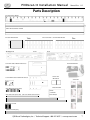
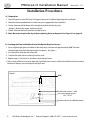
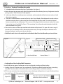
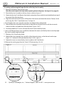
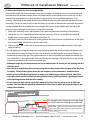
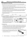
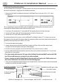
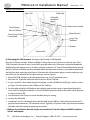
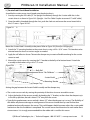
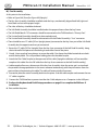
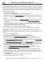
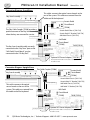
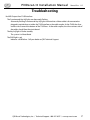
QRS Music Technologies, Inc.
PNOscan II
Installation Manual
Item # 79217C
Manual # IM792171
Rev. 1.01
Manual Rev. 1.15
Warnings
FCC INFORMATION
1.IMPORTANT NOTICE: DO NOT MODIFY THIS UNIT!
This product, when installed as indicated in the Installation Manual, meets FCC, CE, Chinese CE and Australia CE requirements. Modifications not expressly approved by QRS Music Technologies, Inc. may void
your authority, granted by the FCC, to use this product.
2.IMPORTANT: When connecting this product to accessories and/or another product use only high quality
shielded cables. Cables supplied with this product MUST be used. Follow all installation instructions.
Failure to follow instructions could void your FCC authorization to use this product in the United States of
America.
3.NOTE: This product has been designed to comply with the requirements listed in the FCC Regulations, Part
15 for Class “B” digital devices. Compliance with these requirements provides a reasonable level of assurance that your use of this product in a residential environment will not result in harmful interference with
other electronic devices. This equipment generates/uses radio frequencies and, if not installed and used
according to the instructions found in the Installation Manual, may cause interference harmful to the operation of other electronic devices. Compliance with FCC regulations does not guarantee that interference will not occur in all installations. If this product is found to be the source of interference, which can
be determined by turning the unit “OFF” and “ON”, please try to eliminate the problem by using one of
the following measures:
•Relocate either this product or the device that is being affected by the interference.
•Utilize power outlets that are on different circuits (circuit breaker or fuse) or install AC line filters.
If these corrective measures do not produce satisfactory results, please contact the local authorized distributor, or contact QRS Music Technologies, Inc. 269 Quaker Drive Seneca, PA 16346.
Table Of Contents
Welcome
Brief Description
Tools And Materials List
Parts List
Parts Description
Installation Procedures
A ] Preparation
B ] Locating the Front to Back Position of the Optical Key Scan Sensors
C ] Key Scan - Track and Circuit Board Assembly
⇒ Locking Verses Non-Locking Cable Connectors
D ] Connecting the Four Key Scan Circuit Boards
E ] Establishing the Bass/Treble Position of the Key Scan Circuit Boards - Function Test
F ] Locating and Securing the Proper Position of the Key Scan Assembly
G ] Setting the proper Key Scan Assembly Height
H ] Dressing the Key Scan Assembly Cables
I ] Preparing the Keys
J ] Soft Pedal Circuit Board Installation [Grand & Upright]
K ] Mounting the TUSB Interface
L ] Sustain Pedal Circuit Board Installation [Grand & Upright]
M ] Final Assembly
Keyboard Setup
Pedal Setup
Component Placement [Grand & Upright]
Operating Modes / Standard Version and Version 45 (Used with QRS Sound Module)
TUSB Interface Rear Panel Connections
TUSB Interface Front Panel
Connection Diagrams [Grand & Upright]
Troubleshooting
Warranty
4
5
6
7
8
9
10
11-13
14
15
16
17
18
19
20
21
22
23
24
25
26
27
28-29
Accessories
QRS Part #
Description
Purpose
Unless your using a QRS Ancho or Petine controller with PNOscan II, one of these two cables is required to use PNOscan.
50126
USB A Male - 5 Pin Mini B
Connects PNOscan II to a computers’ USB port
70153
20’ MIDI Cable [10’ = 70152]
Connects PNOscan II MIDI Out to a MIDI device
79208
Sostenuto - A Sost Pedal Circuit board can be ordered and connected to the “Sost” connector on the Soft Pedal
Sensor board to monitor the Sostenuto pedal on the piano. Order: 1-79208; 1-7921734; 1-1790185; 1-7921736; 17921770; 2-70585
Upright Conversion Kit
QRS Part #
Description
79217UC
Parts added to this kit for installation into an Upright piano.
P N O s c a n I I I nstallation M a nual
Manual Rev. 1.15
Welcome
Will you be connecting this PNOscan II record system to a QRS Petine controller?
If so, you will need a MIDI Adapter Cable, #99140, and set the jumper on the Petine!
Please read through these installation instructions prior to attempting the installation. Taking the time to
understand this product before starting and exercising care during the installation will promote immediate
success.
On which keyboard instruments can I install a PNOscan II sensor strip? The PNOscan II was designed in
such a manner that it can be installed in virtually any piano. For most acoustic pianos the installation
process is straightforward. Occasionally with pianos, and more frequently with organs and other keyboards,
a successful installation will require some creativity on the installer's part.
Acoustic pianos: There must be enough room between the bottom of the key and the highest portion of
the key frame so that the key does not hit the sensor housing. Fortunately, for most acoustic pianos this is
not a problem. More than likely you will have to shim the sensor strip higher.
Please unpack your kit and report any damage or missing parts immediately. See page 6 for the complete
parts list.
Brief Description
Key Scan Assembly: The key scan assembly consists of a series of optical sensors, one for each key. Each
optical sensor has one small plastic "tower." The tower transmits and receives a beam of infrared light .
As the key moves it gradually changes the intensity of the amount of light detected. The assembly is
mounted to the key frame, positioned so that the bottom of each key reliably reflects the light. Since it
is optical, absolutely nothing effects the touch of the key. The travel of the key is not restricted by the
assembly - each key still has the same range of motion it had before. The Key Scan Assembly consists of
four printed circuit boards inserted in a metal track.
Pedal Sensors: Although PNOscan II was designed to detect the movement of all three pedals, only two
Pedal Sensors are supplied with the PNOscan II system. The smaller “Sustain” Pedal Board is used to detect
motion of damper tray on a Grand, or the Pedal Lever on an Upright, when the sustain pedal is depressed.
The larger “Soft” Pedal Board” detects movement of the key frame on a Grand, or the Hammer Rail on an
Upright, when the soft shift pedal is depressed.
TUSB Interface: The TUSB Interface is the control center for the system. Used to setup, or calibrate, the
sensors after the installation. Lights indicate activity and buttons are used to change operating modes. The
interface transmits MIDI data, allowing the user to connect to external synthesizers and sequencers.
4
QRS Music Technologies, Inc. / Technical Support - 800-247-6557 / www.qrsmusic.com
P N O s c a n I I I nstallation M a nual
Manual Rev. 1.15
Tools and Materials List
Below is a list of recommended tools and materials you should have on hand prior to the installation. Keep
in mind that piano design and construction differs widely amount brands and models. Having access to a
general supply of wood stock, glues and other materials can save you time and generally make the install
go smoothly and easily.
Tools
Materials
Cordless drill and screw bits
1/4" and 1/2" plywood, small pieces
Drill bits
Double sided tape
Phillips screw drivers: #1 and #2
Masking Tape
Large flat blade screwdriver
Black latex paint or extra large permanent black marker
Fine needle nose pliers
Wood glue
Razor knife with new blades
Shim stock assortment (non-compressing)
Sharp wood chisel
Gaffers tape or duct tape
Good blunt nose tweezers
Jumbo Size Black Magic Marker
6" rule calibrated in 1/32"
Small combo square
Sharp pencils
4' straight edge
Feeler gauges (Could use old credit cards)
Computer with sound card or MIDI sound module
Additional Tools
Although these tools are not normally required you may work on a piano with unique requirements.
Jig saw with medium tooth blade
6 or 8 oz ball peen hammer
Center punch
1" paddle drill bit
6' tape rule
QRS Music Technologies, Inc. / Technical Support - 800-247-6557 / www.qrsmusic.com
5
Parts List
Please inspect each component as you unpack the system and report any discrepancies or shortages immediately.
QTY
PART #
DESCRIPTION
4
79205
KEY SCAN CIRCUIT BOARD
3
79228
ALUMINUM KEY SCAN TRACK - PINNED [PINS=7921726]
1
79228
ALUMINUM KEY SCAN TRACK - NON-PINNED
5
7921756
KEY SCAN TRACK MOUNT [ 10 - #4-40X1/8” PANHEAD SCREW] [ 10 - #4X3/4” PANHEAD SCREW]
20
7921768
SHIM - THICK [ USE WITH KEY SCAN TRACK MOUNTS]
40
7921758
SHIM - THIN [ USE WITH KEY SCAN TRACK MOUNTS]
1
79210
TUSB INTERFACE [2 - #6X1/2” PANHEAD SCREW]
1
7921701
AC/DC POWER ADAPTER [INPUT: 100-240V 50-60HZ 9.2A
1
79209
SOFT PEDAL CIRCUIT BOARD [1 - #4X3/16” PANHEAD SCREW]
1
7921732
SOFT PEDAL CHASSIS [1 - #4X3/16” PANHEAD SCREW]
1
79208
SUSTAIN PEDAL CIRCUIT BOARD [1 - #4X3/16” PANHEAD SCREW]
1
7921734
SUSTAIN PEDAL CHASSIS [2 - #4X3/16” PANHEAD SCREW]
1
7921770
“L” BRACKET: SUSTAIN PEDAL MOUNTING [*ADDITIONAL FOR UPRIGHT INSTALLATION: SOFT PEDAL REFLECTOR]
1
7921706
CABLE: 38” 10-PIN FLEX [TSUB-SOFT PEDAL]
(1*)
790185
CABLE 60” 6-PIN FLEX [*REQUIRED FOR UPRIGHT PIANO INSTALLATIONS ONLY]
1
7921718
CABLE: 20” 6-PIN FLEX [SOFT PEDAL/SUSTAIN PEDAL]
2 (*)
7921704
CABLE: 12 “ 6-PIN [KEY SENSOR/SOFT PEDAL] [*ONLY 1 REQUIRED FOR UPRIGHT PIANO INSTALLATIONS]
3
7921703
CABLE: 4.5” 6-PIN WAVED FLEX [KEY SENSOR/KEY SENSOR]
2
79206
FLEX CABLE COUPLER
1
7921754
CABLE: 1 METER [USB MINI B EXTENDER]
2
7921736
SENSOR TAB [OPTICAL SENSOR REFLECTOR FOR SUSTAIN AND SOFT SHIFT]
10
70208
CLAMPS “WAVE” [ 10 - #6X1/2” PANHEAD SCREW]
7
7921764
1” SQUARE OF SILVER TAPE (SECURES KEY SENSOR BOARDS TO METAL KEY-SCAN TRACKS)
70585
SCREW - 6X1/2” [PARTICLE BOARD] [2-TUSB; 1- “L” BRACKET; 10-WAVE CLAMPS] [* ADD 2 FOR UPRIGHT]
10
7921760
SCREW - 4X3/4” [PHILLIPS - TRUSS] [ATTACHES KEY SCAN TRACK MOUNTS TO KEY FRAME]
5
7921744
SCREW - 4-24X3/16” [SUSTAIN & SOFT PEDAL]
10
7921742
SCREW - 4-40X1/8” [ATTACHES METAL KEY SCAN TRACK TO THE TRACK MOUNTS]
(1*)
70581
“L” BRACKET: SOFT PEDAL SENSOR TAB MOUNT [*UPRIGHT PIANO INSTALLATION]
1
IM792171
INSTALLATION GUIDE
1
OM79217
USER GUIDE
1
7921766
PNOSCAN WARRANTY CARD
79217UC
UPRIGHT CONVERSION KIT [ 1-790185; 1-70581 & 2-70585]
15(2*)
6
OUTPUT: 5VDC 1.0A CENTER +]
P N O s c a n I I I nstallation M a nual
Manual Rev. 1.15
Parts Description
KEY SCAN CIRCUIT BOARD
METAL KEY SCAN TRACK - PINNED
KEY SCAN TRACK MOUNT
MULTI SHIM PACK - USE WITH TRACK MOUNTS
Thick
TUSB INTERFACE
FRONT
REAR
AC POWER ADAPTER
SOFT PEDAL CIRCUIT BOARD AND CHASSIS
SUSTAIN PEDAL CIRCUIT BOARD AND CHASSIS
6-PIN WAVED FLEX CABLE [4.5”]
6-PIN FLEX CABLE [12” & 20”] [ 60” FOR UPRIGHT INSTALLATIONS]
Thin
SENSOR TAB
“REFLECTOR”
SILVER TAPE
MISC PARTS BAG
SCREWS
“L” BRACKET
Wave Clamps
FLEX CABLE COUPLER
10-PIN FLEX CABLE [38”]
QRS Music Technologies, Inc. / Technical Support - 800-247-6557 / www.qrsmusic.com
7
P N O s c a n I I I nstallation M a nual
Manual Rev. 1.15
Installation Procedures
A ] Preparation
1. Check the parts in your PNOscan II kit against the parts list before beginning this installation.
2. Check the recommended tool list to be sure your equipped for the installation.
3. Grand - Remove the fall board, left and right key blocks and the key slip.
Upright - Remove the upper and lower panels.
4. Grand - Remove the key action from the piano case.
5. Note: Be certain to paint the keys before replacing them in the piano. See Figure 21 on page 16.
B ] Locating the Front to Back Position of the Optical Key Scan Sensors
1. Set a straight edge against the back of the sharp keys and measure approximately 3/16" from the
straight edge toward the front end of the sharp keys. See Figure 1.
2. Use a pencil to mark the side of key #88.
3. Transfer the marks down to the key frame as well.
4. Repeat steps 1-3 for key #1 at the bass end of the key frame.
• These marks will later be used to align the Optical Key Scan sensors which will establish the front to back
location of the key scan assembly on the key frame.
Figure 1
3/16”
Pencil mark on keys 1 & 88
Key Scan Optical Sensors
OP1 - OP22
Pencil mark bass & treble key frame
8
QRS Music Technologies, Inc. / Technical Support - 800-247-6557 / www.qrsmusic.com
P N O s c a n I I I nstallation M a nual
Manual Rev. 1.15
C ] Key Scan - Track and Circuit Board Assembly
1. Assemble the four Aluminum Key Scan Track sections. See Figure 2.
• Notice that one joint pin protrudes slightly further than the other allowing for easy of alignment into the
joining sections. Slide all sections firmly together.
2. Add a strip of the silver-metal tape across each joint, on the underside of the aluminum tracks, to hold
the sections together.
3. There are 3 cable connectors on each of the Key Scan Circuit Boards. Slide the boards into the tracks so
that the connector closest to the end of the circuit board faces left (bass end). This puts the Optical
Sensors towards the rear of the piano. These sensors will be aligned with the marks you made on the action
frame and on keys #1 and #88. See Figure 1. The remaining 3 circuit boards need to be placed with the
same orientation. See Figure 3.
• There are four pieces of fiber tape attached to the bottom of the boards. This tape will insure a snug fit
into the tracks so the boards won’t slide out of position easily. The tape also helps to eliminate noise
between the boards and the track due to vibration.
⇒ Hold the boards close to the metal track so the boards don’t bend and break as you insert them.
Figure 3
Figure 2
Aluminum Track
Key Scan Circuit Board
Aluminum Track
Key Scan Circuit Board
Optical
Sensors
(OP 1-22)
Optical Sensor OP 22
Aluminum
Tracks
Bass End of Piano
Optical Sensor OP 1
Front of Piano
⇒ Locking Verses Non-Locking Cable Connectors
You will see the two types of connectors on the circuit boards; Locking and Non-Locking.
• Locking: Figure 4A. Used on type 1 key scan boards. The lock must be fully pulled out prior to inserting
the cable. Once the cable is inserted the lock must be fully pushed in toward the connector.
NOTE: Use care not to force the connector latches when unlocking or locking them as it is possible to break them.
• Non-lock: Figure 4B. Only requires full insertion of cable.
Figure 4B
Figures 4A
The silver “contact” side of ribbon
cable faces the circuit board.
QRS Music Technologies, Inc. / Technical Support - 800-247-6557 / www.qrsmusic.com
9
P N O s c a n I I I nstallation M a nual
Manual Rev. 1.15
D ] Connecting the Four Key Scan Circuit Boards
1. Orient the Key Scan Assembly so that the Key Scan Circuit Boards are oriented as shown in Figure 5.
Figure 5
Key Scan Circuit Board
Bass Connector
Status/Alignment LED
Optical sensors (OP 1-22)
Treble Connector
Key Scan Assembly
Board 1 [Left]
Board 2
Board 4 [Right]
Board 3
2. Plug one end of a 4.5” 6-Pin Waved Flex Cable into the Treble Connector of Board 1. See Figure 6.
• Insert one end of the cable into a connector and then
gently pull the cable to the length needed to meet the
other connector. When stretching the cable, support the
connected end to keep it from pulling out. Pull the cable
from the opposite end, not from the middle of the cable,
to avoid distorting the cable. Close the lock if present.
3. Plug the other end of the cable into the Bass Connector
of Board 2. See Figure 7.
Figure 6
Figure 7
• Use the two remaining Waved Flex Cables to connect the other Key Scan Circuit Boards.
4. Treble Connector of Board 2 to the Bass Connector of Board 3
5. Treble Connector of Board 3 to the Bass Connector of Board 4
• Typically, there will be humps in these wave cables after the connections are made and they may
interfere with the keys and cause mechanical noise when keys are depressed. If the humps interfere with
your installation jump to section “H” on page 16 to review how to flatten them correctly.
6. Plug one of a 12” 6-Pin Flex Cables into the Treble Connector of Key
Scan Board 4. See Figure 8.
Figure 8
• The Key Scan Assembly should look like Figure 9. The Bass Connector of Board 1 is not used.
Figure 9
10
Board 4 [Right]
QRS Music Technologies, Inc. / Technical Support - 800-247-6557 / www.qrsmusic.com
P N O s c a n I I I nstallation M a nual
Manual Rev. 1.15
E] Establishing the Bass/Treble Position of the Key Scan Circuit Boards - Function Test...
• You will now establish the proper spacing of the Key Scan Boards for your particular piano. The process
we will use to establish this Left/Right alignment will also include an initial bench type functional test
which verifies proper system function, as it is ideal to test the components prior to installation.
1. Grand - Remove the action stack from the key frame.
Figure 10
• Do not remove the keys.
2. Lay the Key Scan Assembly across the width of the keys
and up against the backs of the sharp keys. See Figure 10.
3. Position the metal Key Scan Track Assembly so that
there is an equal amount of over-hang, or under-hang, at
the bass and treble ends of the keyboard. Slide the
assembly against the sharp keys and use a few pieces of
masking tape to temporarily hold the assembly to the
keyboard during the circuit board alignment.
• Connect the components. The reason for making these connections at this time is two fold. First it allows
the system to be verified functionally. In the event there was shipping damage, or some other issue, it’s
best to detect problems now instead of after the system is secured in place. Secondly, there is a green
LED light on each of the 22 note key scan boards. These LEDs are easily visible when the system is
powered on and they will aid you in the mechanical alignment of the key scan boards to the keys.
4. Connect the 6-Pin Flex cable coming from the Treble Connector of Key Scan board 4 (Step D-6 Figure 8)
to the Key Scan socket of the Soft Pedal Circuit Board. See Figure 11.
5. Connect the 10-Pin Flex Cable to the Primary Port of the TUSB interface and to the IN socket of the Soft
Pedal Circuit board.
6. Connect the AC Power Adaptor to the 5VDC socket of the TUSB interface. The unit will power ON.
• When the AC adaptor is plugged into an AC outlet, the PNOscan II system should power on. You will
notice various lights blinking.
Figure 11
Soft Pedal Circuit Board
Treble connector of Key Scan board 4
TUSB
AC Power Adapter
QRS Music Technologies, Inc. / Technical Support - 800-247-6557 / www.qrsmusic.com
11
P N O s c a n I I I nstallation M a nual
Manual Rev. 1.15
E]... Establishing the Bass/Treble Position of the Key Scan Circuit Boards - Function Test ...
7. As a test, place your finger over and in close proximity to the individual Optical “OP” sensors on the key
scan boards. As the sensors are activated you will see a corresponding flicker of the lighted FUNCTION
button on the TUSB as well as the green “Status LED-Align” LEDs on the key scan boards. See Figure 12
• If the system does not respond as described above check your connections and your AC power source.
Figure 12
• These green LED “Status ” lights, one on each board, indicate activity as MIDI data flows through the
system. It also indicates the system’s mode as follows:
QRS Mode - Light blinks once, then a pause.
-
MIDI output is optimized for Pianomation acoustic record and playback.
MIDI Sound Module Mode - Light blinks twice, then a pause.
- MIDI output is optimized for playback through a sound module.
- The output level of this mode is greater that that of the Record Mode.
Mute Mode: Light flashes steadily.
- Stops MIDI output from PNOscan II.
• The LEDs also help to determine the proper left to right location of the Optical Sensors under each key.
The placement of these “Status” LEDs is in a very specific location on the circuit board, and when they
are positioned properly between certain keys, they will confirm that each Optical Sensor is positioned
correctly under it’s respective key.
• It is not likely all of the sensors will align at the exact center of the keys. Therefore, alignment must be
averaged across the groups of 22 notes. The “Status” LED must always end up within it's corresponding
key gap.
12
QRS Music Technologies, Inc. / Technical Support - 800-247-6557 / www.qrsmusic.com
P N O s c a n I I I nstallation M a nual
Manual Rev. 1.15
E]...Establishing the Bass/Treble Position of the Key Scan Circuit Boards - Function Test
• Starting with Key Scan Board #1, at the bass end of the keyboard, visually align the individual Optical
Sensors with each key, keeping the “Status” LED aligned with the gap between keys 11 and 12. Figure 13.
8. Adjust Board #1 to align the Optical Sensors while keeping the “Status” LED between keys 11 & 12.
9. Place a piece of Silver Tape over the track and board to secure it’s position.
• Do not place the tape over any exposed “silver” trace or component on the board.
10. Repeat steps 8 & 9 for Key Scan boards 2, 3 & 4, aligning the “Status” LEDs as follows:
11. Adjust Board #2 to align the Optical Sensors while keeping the “Status” LED between keys 33 & 34.
12. Adjust Board #3 to align the Optical Sensors while keeping the “Status” LED between keys 55 & 56.
13. Adjust Board #4 to align the Optical Sensors while keeping the “Status” LED between keys 77 & 78.
14. Use a fine tipped marker to place a mark on each of the metal tracks where the green LED is located.
• Once installed, the LEDs can be seen when looking down through the spaces between the keys.
Figure 13
Masking Tape
Slide the boards within the track and
align the sensors to the keys
keeping the “Status” LED
between selected keys.
Silver Tape
Mark the track at each “Status” LED
15. Place a small piece of masking tape over the “Status” LED on Key Scan Board #2.
• Press on the tape so that the outline of the LED is clearly visible.
Figure 14
16. Using a pencil, draw a line on the tape that is centered in the space between
keys 33 & 34. Figure 14.
• We will use this mark later to align the bass to treble position of the Key Scan
Assembly under the keys.
• With the function test complete, the key sensor strip now properly scaled to the key spacing and locked
in place with tape, you are ready to continue the installation.
17. Unplug the AC Power Adapter from the wall outlet.
18. Disconnect the Key Scan Assembly by unplugging the cable from the Key Scan connector on the Soft
Pedal Circuit Board.
19. Now remove any PNOscan items from the keyboard and set them aside while the keys are removed.
• Be careful with the Key Scan Assembly to avoid knocking the boards out of alignment.
• Always set the assembly in a safe place and lay it on a flat surface, do not set on end!
20. Use a straight edge and align it with the two marks you made on key 1 and key 88. Use a pencil and
strike a light line across all 88 keys.
QRS Music Technologies, Inc. / Technical Support - 800-247-6557 / www.qrsmusic.com
13
P N O s c a n I I I nstallation M a nual
Manual Rev. 1.15
F] Locating and Securing the Proper Position of the Key Scan Assembly
1. Remove all of the keys from the key frame.
Note: Be certain to paint the keys before replacing them in the piano. See Figure 21 on page 16.
2. Place the Key Scan Assembly on the key frame as shown in Figure 15.
3. Obtain the Key Scan Track Mounts from the kit and position them under the track and directly on top of
the vertical slats of the key frame.
4. Align the metal track into the recess of the plastic track mounts and attach the mounts “loosely” to the
track using the 4-40 x 1/4 pan head screws. See figure 16.
• We will tighten the screws once the exact bass to treble position is determined.
5. Move the Key Scan Assembly, front to back, to align the row of Optical Sensors with the two marks
made on the bass and treble ends of the key frame. Figures 15 & 17.
6. Use the provided 4x3/4” screws to fasten the mounts to the wood key frame.
• Later we will loosen these screws to add shims between the mounts and the key frame to set the proper
Key Scan Assembly height and angle.
7. Place keys 33 & 34 on the key frame.
8. Slide the Key Scan Assembly, bass to treble within the track mounts, so that the mark on the tape
(Figure 14) is centered in the space between keys 33 & 34. Figure 17.
9. Tighten the screws to secure the Key Scan Assembly to the Track Mounts.
10. Remove the masking tape from the “Status” LED between keys 33 & 34.
Figure 15
14
Key 34
Figure 17
Key 33
Figure 16
QRS Music Technologies, Inc. / Technical Support - 800-247-6557 / www.qrsmusic.com
P N O s c a n I I I nstallation M a nual
Manual Rev. 1.15
G] Setting the Proper Key Scan Assembly Height
Now that the proper Key Scan Assembly’s front to back and bass to treble position is secured to the track,
and with the track secured to the key frame, the proper height of the optical sensors can be set. It is very
important for good performance that the distance between the sensors and the key bottoms is set
correctly. Depending on the model of piano you will find that the sharp keys generally dip lower than the
natural keys. For this reason we will use the sharp keys as our point of reference for our height adjustment.
Use the included shims to establish the correct height. More shims can be added under the rear of the
mounts to adjust the angle of the sensors to match the key angle.
1. Place a few sharp keys across the keyboard. Don’t place any above the mounting screw positions.
2. Loosen the #4 x 3/4" mounting screws and add the necessary shims as you establish the required
height measurements across the keyboard. See Figure 18.
3. Add shims under the Track Mounts to set the gap from the Optical Sensors to the bottoms of the sharp
keys at about 0.60” [the thickness of two credit cards].
4. Add extra shims, the smaller size, to tip up the rear of the Key Scan Assembly to conform to the slight
angle of the keys.
• By fully dipping the sharp keys and measuring the gap between the sensor and sharp key bottoms you
can establish the vertical setting of the Key Scan Assembly. Use feeler gauges or a known thickness of
cardboard to measure the gap. The typical credit card is .030' or should be considered the smallest gap
you would allow. Two stacked credit cards would create the ideal gap. The typical business card would
create only one fourth of the minimum required gap.
⇒ When pressing a key for measurement use just a medium force to ensure you are pushing into the
felt dip washer.
⇒ Use care when establishing this vertical setting that the key cannot strike any part of the Key Scan
Assembly. The most likely place where this can happen is at the connectors, located at three
places on each of the Key Scan Boards. In many cases adding more shim to the back side of the
scan rail mounts and less to the front during height setting, will help achieve a good gap distance
while avoiding contact with the rail assembly.
⇒ In rare cases you may need to notch the bottom of the key in the connector areas to eliminate
contact. This must be considered for allowance of action wear in which will cause the keys to dip
deeper after break-in.
Figure 18
Sharp Key-Depressed
Set the gap from the Optical Sensor to the Sharp
key at 0.60” about the width of two credit cards.
Add more shims at the back so that the
key sensor boards are parallel with the
Thick shim depressed key.
Thin shim
QRS Music Technologies, Inc. / Technical Support - 800-247-6557 / www.qrsmusic.com
15
P N O s c a n I I I nstallation M a nual
Manual Rev. 1.15
H ] Dressing the Key Scan Assembly Cables
Once the height of the scan rail assembly is fixed you will need to dress the interconnecting cables.
• Check that the three wave cables used to connect the Key Scan Circuit Boards lay flat against the boards
and don’t touch any keys that are depressed. See Figure 19.
1. Use blunt nose tweezers to squeeze the cable to lay flat against the board. Squeeze in the middle of a
wave will keep the cable straight. Once the cables are properly tightened and adjusted they should be
laying flat against the circuit board. See Figure 19.
• If you have problems getting the cables to lay completely flat you can use a thin piece of tape or a single
drop of super glue under one wave of the cable near the middle. As a last resort you can unplug the
wave cables and stretch them to remove the waves. Reconnect and fold the cables so they lay flat
against the boards. Tape or glue if necessary.
• Tap on the key frame and listen for noise. from the wave cables against the boards and for the boards
rattling within the metal tracks.
Figure 19
Fold
or
Pinch
2. Prepare the 12" cable [20” for upright pianos] exiting the treble end of the Key Scan Assembly with an
immediate 90 deg fold pointing frontward and
then wrapping down and around the front edge of Figure 20
the track. Continue routing under the track
followed by an immediate 90 deg bend pointing
right. Once the cable is positioned use a couple
pieces of tape to hold in place. This orients the
cable in the proper direction and keeps the cable
clear of key's and sensors. See Figure 20.
I ] Preparing the Keys
1. For optimum performance, darken the sides of all keys to reduce light reflections. Centered on the line
you scribed on the keys, create a 1" long x 1/2" high fill using a extra large permanent marker or paint
pen. We suggest a jumbo size magic marker. Use care not to get paint on the bottom of the keys and
not to color too high up the key as to make it viable when adjacent keys are depressed. Figure 21.
Be sure to remove and color the sides of the keys originally left on the key frame.
2. With the key sensor rail adjusted and secured place the piano keys back onto the key frame.
3. With all keys darkened and reinstalled onto the frame, the action
stack can be placed back on the key frame. Place the key/action
assembly back into the piano case.
16
Figure 21
QRS Music Technologies, Inc. / Technical Support - 800-247-6557 / www.qrsmusic.com
P N O s c a n I I I nstallation M a nual
Manual Rev. 1.15
J ] Soft Pedal Circuit Board Installation
This circuit board has two functions. It actually contains the sensors that read the soft shift movement of
the action and provides a single point for all cable connections.
1. Mount the Soft Pedal Circuit Board to the plastic Soft Pedal Chassis using the 4-24 X 3/16” screw.
See Figure 22.
Figure 22
=
This is a good time to connect all cables to the soft pedal board. Making these connections prior to
mounting the soft pedal board makes cable connection easier.
2. From Figure 20, connect the 12" 6-pin cable [20” for Upright pianos] to the Key Scan port.
3. Connect a 20" 6-pin cable [60” for Upright pianos] to the Sust (Sustain) port.
4. Connect the 38” 10-pin (wide) cable to the IN port.
The working distance for the sensors on the Soft Pedal Circuit Board is about 1/2". In most cases you can
find a place on the side wall of the piano where the movement of the main action frame can be captured. A
grand key/action generally moves about 1/4" or less.
5. Put the action back into the piano.
6. Locate a place to mount the Soft Pedal Chassis where it will face a flat area of the action frame.
See Figure 23A for Grand pianos and Figure 23B for Uprights.
• Check that the return spring does not rub the Soft Pedal Chassis when the action is shifted.
• You may need to add a block of wood to space the sensor out to achieve a distance of 1/2" to 5/8" with
the action in it's rest position.
⇒ The 10-pin (wide) cable from the “IN” port of the Soft Pedal Circuit Board MUST reach to the TUSB
box. There are NO extensions or longer 10-pin cables available.
⇒ Choose a location for the Soft Pedal Board so that the cables will reach to the TUSB Interface and
the Sustain Pedal Board. See sections K & L on the following pages.
7. Once you have selected a location based on the said parameters, remove the action from the piano and
proceed to install the soft pedal assembly.
Grand Piano Installation Figure 23A
USB MINI B to USB Type A Cable
To the TUSB box
Flex Cable Coupler
To the Sustain Pedal
Circuit Board.
To the Key Scan Assembly
Optical Sensors
QRS Music Technologies, Inc. / Technical Support - 800-247-6557 / www.qrsmusic.com
17
P N O s c a n I I I nstallation M a nual
Manual Rev. 1.15
Upright Piano Installation
Figure 23B
Treble side
Soft pedal
board and
chassis.
Hammer
To Key Scan Assembly
To the Primary
Port of TUSB box
Optical Sensors
To the Sustain Pedal
Circuit Board.
Sensor Tab
“Reflector”
“L” Bracket
Hammer Rail
K ] Mounting the TUSB Interface See figures 26A [Grand] or 26B [Upright]
Place the TUSB user interface "buttons and lights" where they are easy to access and can be seen. If the
TUSB is located with ease of access in mind this generally means you will mount it under the keybed and
held back from the edge an inch or so. When using this method a 3/4" hole will need drilled down through
the bed. The hole should be near the soft pedal board and positioned so there is no interference between
the hole, key block, piano leg or key frame. If the piano has a Pianomation player system installed you can
most likely use the solenoid slot for cable routing as seen in Figure 23.
1. Mount the TUSB interface at the desired location using 2 6x1/2" pan head screws.
2. Route the 30” 10-pin flex cable into the Primary Port of the TUSB box.
3. As you run the 30” 10 pin cable through the keybed, run the USB MINI B to USB Type A cable as shown
on Figure 23A and connect to the USB port of the TUSB box.
4. Run the other end of the USB cable up the treble rim and securely mount it somewhere behind the
music shelf. For Upright installations, run the USB MINI B extension cable to the treble side of the piano
as shown in Figure 26B.
5. Use the plastic wave clamps to secure the cable along it's routing.
6. Connect the USB cable.
7. Locate the 5 volt AC wall adaptor and route the cable to the TUSB box. Select a location where the AC
pack can be connected to a 120 volt power source. Typically a AC power outlet strip will be mounted on
the under side of the piano for powering accessories.
⇒ PNOscan II installations that will only be connected to a PC via the USB port will NOT need the 5
Volt AC wall adapter.
18
QRS Music Technologies, Inc. / Technical Support - 800-247-6557 / www.qrsmusic.com
P N O s c a n I I I nstallation M a nual
Manual Rev. 1.15
L ] Sustain Pedal Circuit Board Installation
Assemble the sustain sensor circuit board onto the plastic chassis.
1. Start by weaving the 20" cable [12” for Upright installations] through the 3 strain relief slots in the
sustain chassis as shown in Figure 24 A. [Upright - Use Flex Cable Coupler to connect12” to 60” cable]
2. Once the cable is threaded through the slots, push the slack out and secure the sensor board with a
#4x1/4" screw. Figure 24 B & C.
Figure 24
A
C
B
Mount the Sustain Pedal Assembly to the piano. Refer to Figure 25A [Grand] or 25B [Upright].
3. Attach the "L" mounting bracket to the sustain chassis using a 4-24 X 3/16” screw. This bracket can be
oriented onto the chassis at various angles as needed.
4. Apply the self adhesive Sensor Tab onto the damper tray to create a flexible overhang for the sustain
sensor to read.
5. Mount the sustain sensor by screwing the “L” bracket to the belly rail or bottom board. Attach the
assembly to the bracket using a #6 x 1/2" screw.
Figure 25A
Grand
Figure 25B
Upright
Belly Rail
Sensor Tab “Reflector”
Sustain Pedal
Mounting Bracket
Damper Tray
Setting the gap between the Sustain Pedal Assembly and the damper tray.
• The sustain sensor works by sensing the proximity of the tab as it moves toward the sensor.
6. Adjust the height of the sensor assembly, by bending the “L” bracket, so than when the damper tray is
in the full up position, the tab is about 1/16" away from the sensor.
• Typically the gap between sensor and tab is about 1/2" when the damper tray is at rest. The flexibility of
the rubber tab prevents damage or misalignment of the sensor should the tray travel further than
predicted and actually contacts the sensor. This could happen should someone adjust the sustain pedal
mechanism after the installation is completed. The sustain sensor should continue to work under these
circumstances. It is strongly recommended that the rubber tab is used for this reason.
QRS Music Technologies, Inc. / Technical Support - 800-247-6557 / www.qrsmusic.com
19
P N O s c a n I I I nstallation M a nual
Manual Rev. 1.15
M ] Final Assembly
At this point in the installation...
• Refer to Figure 26A [Grand] or Figure 26B [Upright].
• The Key Scan Assembly should be installed under the keys, mechanically aligned both left/right and
front/back and set to the proper height.
• The sides of the keys should be darkened.
• The Soft Pedal Assembly should be installed and at the proper distance from the key frame.
• The Soft Pedal Board’s “IN” connector should be connected to the TUSB Interface’s “Primary Port”.
• The Sustain Pedal Assembly should be in place and adjusted.
• The Sustain Pedal Assembly should be connected to the Soft Pedal Assembly’s “Sust” connector.
• There should be one 12" cable [20” on Upright pianos] connected to the Key Scan port of the Soft Pedal
Assembly but, the opposite end not yet connected.
1. Route the 12” cable [20” for Uprights] from the Key Scan connector of the Soft Pedal Assembly along
the inside wall of the piano case extending it toward the front of the piano.
2. Grand - Use a couple of wave clamps to secure the cable. One clamp should be located close to back
end of the key block. This will provide a holding place for the cable coupler.
3. Attach the Flex Cable Coupler to the open end of this cable. [Upright installations will not need the
coupler at this cable. Run the 20” cable from the key Scan connector to the Soft Pedal Assembly].
• A cable coupler allows easy disconnect of the Key Scan Assembly when the action get's serviced and
also provides damage protection in the event someone inadvertently pulls the piano action from the
piano without disconnecting the cable. The cable will automatically disconnect.
4. Proceed to place the action assembly back into the piano. Grab the cable coupler and connect the two
12" cables together.
5. Connect the TUSB Interface to power via either the 5 Volt adapter or to a Computer via the USB port.
5. Perform the Keyboard and Pedal Setup procedures on page 21 to complete the PNOscan II
installation.
6. Reassemble the piano.
20
QRS Music Technologies, Inc. / Technical Support - 800-247-6557 / www.qrsmusic.com
P N O s c a n I I I nstallation M a nual
Manual Rev. 1.15
Keyboard Setup: To make the setup process easier, connect the MIDI Output of PNOscan II to a soundcard
equipped QRS Pianomation controller or to a MIDI sound module. As you depress each piano key during
setup you will need to hold the key down until the system accepts the key's down position. To indicate the
position has been accepted, the PNOscan II system outputs a midi note. Alternately if you don't have a MIDI
device connected, you can reference the green light on the Function button. Each time a key position is
accepted this button will light.
1. Press and hold the “Key Adj“ button.
2. While holding the “Key Adj” button, press and hold the “Function” button.
3. Hold both buttons in until the 'Key Adj" light flashes, release both buttons, wait for rapid flash to stop.
• The system is now in keyboard adjust mode and all previous key calibration values in memory have been
erased.
4. Once in the setup mode, start with key # 1, pressing the key firmly through its entire travel. Hold the key
down until you either hear the note play through the speaker or until the Function button lights
momentarily.
⇒ It is very important that you hold the key down until it is accepted as a position. This is normally
instantaneous but sometimes takes a couple of seconds.
5. Repeat this process for each key until all 88 notes have been accepted.
• After this process no further action is required from the user and the keyboard setup is complete.
Pedal Setup: Use the following sequence to setup the pedals. Note that the standard configuration
includes a soft pedal and a sustain pedal. The Sostenuto sensor is optional. If used, this pedal adjusts in the
same way.
1. Press and hold the “Pedal Adj” button.
2. While holding the “Pedal Adj” button, press and hold the "Function" button.
3. Hold both buttons until the "Pedal Adj" button starts flashing, then release both buttons.
• The system is now in pedal setup mode and all previous pedal values in memory have been erased.
4. Firmly press the sustain pedal fully down and hold. Watch the "Function" button for a quick green flash
and then release the pedal.
5. Firmly press the soft pedal fully down and hold. Watch for a quick green flash then release the pedal.
⇒ Be sure you see the quick flash for both pedals. If you do not see this flash exit setup by pressing
the Pedal Adjust button and then reenter pedal setup mode and start again.
6. Return to the sustain pedal and slowly start pressing the pedal down. As the pedal moves down you
will see the Function button start to flash. Hold this pedal position.
• This indicates you are in the range of a acceptable trigger point. At any point in the pedals position,
while the green light is flashing, pressing the "Pedal Adj" button will set that pedal position as the point
where midi sustain event will occur. Typically this point should be at the same exact point where the
actual dampers start to lift.
7. Press "Pedal Adj" one more time to save the settings and exit adjust mode.
8. Release the pedal, the setup procedure is complete.
QRS Music Technologies, Inc. / Technical Support - 800-247-6557 / www.qrsmusic.com
21
P N O s c a n I I I nstallation M a nual
Figure 26A
Grand
Treble end of damper tray
USB extension cable [7921754]
from TSUB USB 2.0 socket.
Manual Rev. 1.15
See page 26 for connection diagrams
Cable Coupler [79206]
Soft pedal sensor:
Chassis [7921732]
Circuit board [79209]
12” 6-pin cable [7921704]
20” 6-pin cable
Sensor tab
“Reflector”
Sustain pedal sensor:
Chassis [7921734]
[7921736]
Circuit Board [79208]
Bracket [7921770]
[7921704]
30” 10-pin cable
[7921706]
12” 6-pin cable [7921704]
Treble end of
piano keyboard
USB
Extension
Keyscan circuit board 1 of 4 [79205]
TUSB Interface [79210]
TUSB
USB extension cable [7921754]
No 5VDC adapter needed when connected to PC.
Figure 26B
Upright
Soft pedal sensor:
Chassis [7921732]
Circuit board [79209]
Sensor tab
“Reflector”
[7921736]
USB
Extension
Bracket [70581]
TSUB is located under
keybed behind lower panel.
Hammer Rail
30” 10-pin cable [7921706]
From TSUB Primary Port
20” 6-pin cable
[7921704] to
Key Scan Assy
60” 6-pin cable [790185]
To Flex Cable Coupler
Sensor tab “Reflector”
[7921736]
12” 6-pin Cable
[7921704] To Flex Cable
Coupler
Sustain pedal sensor:
Chassis [7921734]
Circuit Board [79208]
Bracket [7921770]
22
QRS Music Technologies, Inc. / Technical Support - 800-247-6557 / www.qrsmusic.com
P N O s c a n I I I nstallation M a nual
Manual Rev. 1.15
Operating Modes
Mode 4
Modes 1, 2 & 3
Standard Version
Repeatedly tap the Key Adj button to select one of the following modes:
1. QRS Mode - Light blinks once, then a pause.
• MIDI output is optimized for Pianomation acoustic record and playback.
2. MIDI Sound Module Mode - Light blinks twice, then a pause.
• MIDI output is optimized for playback through a sound module.
• The output level of this mode is greater that that of the Record Mode.
3. Mute Mode: Light flashes steadily.
• Stops MIDI output from PNOscan II.
Version 45 - Used with QRS Sound Module
Repeatedly tap the Key Adj button to select one of the following modes:
1.
QRS Mode - Sound 1- Light blinks once, then a pause.
• MIDI output is optimized for Pianomation acoustic record and playback.
• PNOvoice sends Acoustic Grand Piano sound.
2.
MIDI Sound Module Mode - Sound 2- Light blinks twice, then a pause.
• MIDI output is optimized for playback through a sound module.
• The output level of this mode is greater that that of the Record Mode.
• PNOvoice sends Electric Piano sound.
3.
MIDI Sound Module Mode - Sound 3- Light blinks tree times, then a pause.
• MIDI output is optimized for playback through a sound module.
• PNOvoice sends Church Organ sound.
3.
MIDI Sound Module Mode - Sound 4- Light blinks four times, then a pause.
• MIDI output is optimized for playback through a sound module.
• PNOvoice sends String Ensemble sound.
Tapping the Power button places the unit in System Mute mode: Both versions.
4. System Mute: The Key Adj light flashes steadily.
• Stops MIDI output from PNOscan II and also sends an “All Notes Off” command.
Tap the Key Adj button to exit the Mute mode.
QRS Music Technologies, Inc. / Technical Support - 800-247-6557 / www.qrsmusic.com
23
P N O s c a n I I I nstallation M a nual
Manual Rev. 1.15
TUSB Interface Front Panel
A
Power
A
B
C
D
E
• Press and hold for about 2.5 seconds to power the system off.
• Pressing when the system is off, powers the system on.
• Pressing this button for less than 2 seconds places the system in mute mode and sends a "all notes off"
command to the MIDI Out and USB ports.
This button also has multi function lights:
• Orange indicates that power is being received from the AC wall adaptor or from the USB port.
When both power sources are present the USB port will always be the primary source for system power
unless the host PC cannot deliver the needed current. In this case the AC adaptor will take over.
• Green-Flicker indicates that the USB host has recognized PNOscan II.
• Green indicates that the USB host application is launched and is ready for use.
B
Function
Used in conjunction with other buttons to access the setup functions.
• Green flicker indicates that MIDI date is being outputted.
C
Pedal Adjust
Used to access the pedal setup mode.
• Green light indicates that pedal motion is detected.
D
Keyboard Adjust
Used to access keyboard setup mode.
• Green light indicates the active mode of system.
• There are three modes; QRS, Mute and MIDI Sound Module
E
Expansion
Normally not connected. Future uses include connection to control surface and other integration.
B
Alternately Flashing
D
Alternately flashing Function and Key Adj lights indicate that a ribbon cable is disconnected or plugged in
upside-down at either the TUSB interface or the cable coupler. At the TUSB, the silver-contact side is toward
the bottom of the TUSB box. At the cable coupler, the silver-contact side of the cables should face the
circuit board.
24
QRS Music Technologies, Inc. / Technical Support - 800-247-6557 / www.qrsmusic.com
P N O s c a n I I I nstallation M a nual
Manual Rev. 1.15
TUSB Interface Rear Panel Connections
F
F
G
H
I
J
K
L
Primary Port
Connection to the soft pedal board is made here. This accepts the 10-Pin Flex Cable.
G
Alt Key Port
This port accepts a 6-Pin Flex Cable from the Key Scan Assembly. This port is normally not connected,
although it can be used along with the Primary Port if desired. When only the Primary Port is used then the
Key Scan Assembly gets connected to the Soft Pedal Board.
H
MIDI OUT
Standard MIDI output connection. Connects PNOscan II to sound modules, QRS Pianomation or other MIDI
device.
I
MIDI IN
Standard MIDI input connection. Normally not connected. Used in more complex setups when
communication to diagnostic programs such as the MIDI9 alignment program is needed.
J
USB
Connect a host computer to this port for convenient use of the PNOscan II system and computer software.
USB 2.0 compliant
K
Serial I/O
Used with PNOscan Version 45. Connects to the QRS sound Module. See PNOscan V45 User Guide.
L
5 Volt Input
Connect the AC wall power adapter here. Use only the supplied adapter.
QRS Music Technologies, Inc. / Technical Support - 800-247-6557 / www.qrsmusic.com
25
P N O s c a n I I I nstallation M a nual
Manual Rev. 1.15
Connection Diagram- Grand Piano
This cable connects the optical sensor boards to the
rest of the system. This cable must extend from the
treble end of the keyboard.
Key Scan Assembly
12” 6-pin [7921704]
Sustain Pedal
Circuit Board
[79208]
The Flex Cable Coupler [79206] provides a
quick disconnect of the Key Scan Assembly
when the keys are removed for service.
20” 6-pin [7921718]
Sustain Pedal Chassis [7921734]
Sustain Pedal “L” Bracket [7921770]
Soft Pedal Chassis [7921732]
12” 6-pin [7921704]
Soft Pedal
Circuit Board
[79209]
The Key Scan Assembly cable, currently
connected to the “Key Scan” port on the
“Soft Pedal Circuit Board”, may be
connected to the “Alt Key Port”.
38” 10-pin [7921706]
TUSB [79210]
Optional AC Power Adapter [ 7921701]
Not required when TUSB is connected to a computer via
the USB 2.0 socket.
Connection Diagram- Upright Piano
Flex Cable Coupler [79206]
Key Scan Assembly
Sustain Pedal
Circuit Board
[79208]
12” 6-pin [7921704]
20” 6-pin [7921718]
60” 6-pin [790185]
This cable connects the optical
sensor boards to the rest of the
system. This cable must extend from
the treble end of the keyboard.
Sustain Pedal Chassis [7921734]
Sustain Pedal “L” Bracket [7921770]
Soft Pedal Chassis [7921732]
Soft Pedal “L” Bracket [7921770]
Soft Pedal
Circuit Board
[79209]
38” 10-pin [7921706]
TUSB [79210]
Optional AC Power Adapter [7921701]
Not required when TUSB is connected to a computer via
the USB 2.0 socket.
26
QRS Music Technologies, Inc. / Technical Support - 800-247-6557 / www.qrsmusic.com
P N O s c a n I I I nstallation M a nual
Manual Rev. 1.15
Troubleshooting
No MIDI Output from TUSB Interface
The Function and Key Adj lights are alternately flashing.
Alternately flashing Function and Key Adj lights indicate that a ribbon cable is disconnected or
plugged in upside-down at either the TUSB interface or the cable coupler. At the TUSB, the silvercontact side is toward the bottom of the TUSB box. At the cable coupler, the silver-contact side of
the cables should face the circuit board.
The Key Adj light is flashes steadily.
The system is in Mute Mode
The PWR light is red
Indicates a USB failure - Call your dealer or QRS Technical Support
QRS Music Technologies, Inc. / Technical Support - 800-247-6557 / www.qrsmusic.com
27
PNOscan II™ Limited Warranty
PNOscan II Electronics Limited Warranty
QRS Music Technologies, Inc. (“QRS”) warrants to you for the Warranty Period that there are no defects in the
materials of this Product (as identified at the end of this warranty certificate). The “Warranty Period” expires (except
as explained below) Two (2) years from the date of your purchase of the Product. In order to determine the date of
your purchase of the Product, you will need to provide to us a credit card receipt, a purchase agreement, a sales
slip, a warranty registration or some other form of proof that you are the original purchaser and the date of your
purchase of the Product.
If you are not able to provide us with some form of proof of purchase date, the Warranty Period will be a
shorter period (the “Shorter Warranty Period”) which is two years from the date that your dealer purchased the
Product from QRS. If you cannot provide a proof of purchase date, you may contact us in the manner described
below and we will assist you in determining the date that your dealer purchased the Product from us and
determining the Shorter Warranty Period. This is a warranty is for parts only and does not include shipping or labor.
This warranty does not apply to any accessories you may have purchased with the Product and does not apply to
any piano or components of the piano with which the Product is used or any Piano in which the Product is
installed. In addition, this warranty does not cover scratches, dents or other defects in the cosmetic finish of the
Product.
The warranty is issued solely to the original purchaser of the Product. THIS WARRANTY IS NOT TRANSFERABLE. If,
during the Warranty Period, parts incorporated in this Product are found to be defective in material or
workmanship, and the original purchaser provides Purchase Documents to QRS, then QRS or its authorized dealer
will provide replacement parts without charge. We may, at our discretion, provide reconditioned parts or
assemblies as warranty replacements. You as the original purchaser will be responsible to pay labor costs incurred
in connection with any repair.
LIMITATION IN CONNECTION WITH OBSOLETE PRODUCTS
If at the time you make a claim pursuant to this warranty, we no longer manufacture or sell the same
model of Product, we may, at our discretion, rather than repair or replace defective parts in the Product, offer to sell
you a more current version of a similar Product. If we offer to sell you a more current model of the Product, you will
be responsible to pay the difference between the Manufacture’s Suggested Retail Price (“MSRP”) of the more
current version of a similar Product and the price you paid for the Product you purchased. If you choose not to
accept such offer, we will have no further obligations pursuant to this warranty.
THIS WARRANTY IS IN LIEU OF ANY OTHER WARRANTY, EXPRESS OR IMPLIED, MADE BY THE MANUFACTURER IN
CONNECTION WITH THIS PRODUCT. INCLUDING, BUT NOT LIMITED TO, WARRANTIES OR MERCHANTABILITY OR
FITNESS FOR A PARTICULAR PURPOSE. TO THE EXTENT ALLOWED BY THE LAW, QRS SHALL NOT BE RESPONSIBLE
FOR LOSS OF THE PRODUCT, LOSS OF TIME, INCONVENIENCE, COMMERCIAL LOSS, SPECIAL OR CONSEQUENTIAL
DAMAGES, EVEN IF THE MANUFACTURER HAS BEEN ADVISED OF THE POSSIBILITY OF SUCH DAMAGES.
This warranty gives you specific legal rights. Some states provide other rights, and some states do not allow
excluding or limiting liability for incidental or consequential damage. Consequently, the limitations and exclusions
in this warranty may not apply to you. In addition, some jurisdictions have consumer protection rules, regulations
and statutes that may apply to you.
28
Exclusions
There is no express warranty on the Product and this warranty is void if:
1) You did not purchase this Product from an authorized Pianomation reseller
2) This Product has been serviced, modified or tampered with by anyone other than an QRS Authorized Service
Representative
3) The name, trademark or serial number has been modified, defaced or removed from the product,
4) This Product has been damaged as a result of abuse, abnormal force or strain, failure to reasonably maintain
and protect, modification, accident or exposure to extreme temperature or humidity,
5) Parts, supplies or other accessories which have not been approved by QRS have been used with this Product,
6) Radio frequency interference is generated by uncertified and/or illegal equipment,
7) This Product has been moved or delivered without reasonable preparation and packaging or
8) QRS reasonably determines, after inspection that there has been modification of this Product which adversely
affects the reliability of the product or component.
Owner’s Responsibility
In order to have rights under this warranty, you have the following responsibilities:
1) Retain your proof of purchase and purchase date and send in your Warranty Registration Card
2) Notify QRS or any authorized dealer of any warranty claim within ten (10) days after discovery and provide a
detailed explanation of the problem.
General
If any provision herein shall be unlawful, void or for any reason unenforceable, then that provision shall be deemed
severable from this warranty certificate and shall not affect the validity of and enforceability of the remaining
provisions.
QRS reserves the right to make changes in design and/or improvements to its products without any obligation to
retrofit products previously manufactured.
INSTRUCTIONS FOR OBTAINING WARRANTY SERVICE
1) If you cannot provide proof of purchase, contact QRS at 800-247-6557 and we will attempt to determine the
date on which your dealer purchased the Product and assist you in determining the Shorter Warranty Period.
For warranty service, contact the dealer from whom you purchased the product, or your nearest dealer.
2) If no dealer is near you, contact QRS by phone at 800-247-6557.
3) Do not ship the product without prior written Return Authorization from QRS. Do not attempt to repair or
disassemble the product yourself.
4) Please record your model number and serial number and your date of purchase below for your records. Keep
this information with your proof of purchase in case your product requires service. Do not dispose of the
warranty after it expires. In the event your product ever requires service, these instructions should be helpful
in enabling you to obtain proper service.
Product Model #______________________
Product Serial #_______________________
Date of purchase_______________
29
QRS Music Technologies, Inc.
2011 Seward Ave.
Naples, FL 34109
239-597-5888
239-597-3936 Fax
Copyright © 2006 QRS Music Technologies, Inc.
All rights reserved