1
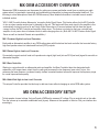
MX SERIES
OEM INTEGRATION
ACCESSORIES
MX-1 / MX-2
MX-3 / MX-4
MX SERIES
OEM INTEGRATION ACCESSORIES
INDEX
PAGE
MX OEM Accessory Overview and Setup............................................................................................................1
Installation............................................................................................................................................................2
MX-1 Feature Descriptions...............................................................................................................................3-4
MX-1 Main Diagram..............................................................................................................................................5
MX-1 Connecting Low Level RCA Cables to Amplifier........................................................................................6
MX-1 Connecting High Level Speaker Wires (with factory amp)........................................................................7
MX-1 Connecting High Level Speaker Wire (no factory amp)............................................................................8
MX-2 Feature Descriptions..................................................................................................................................9
MX-2 Main Diagram............................................................................................................................................10
MX-2 Connecting Low Level RCA Cables to Amplifier......................................................................................11
MX-2 Connecting High Level Speaker Wires (no factory amp)........................................................................12
MX-3 Feature Descriptions................................................................................................................................13
MX-3 Main Diagram............................................................................................................................................14
MX-4 Feature Descriptions................................................................................................................................15
MX-4 Main Diagram............................................................................................................................................16
MX-4 Connecting High Level Speaker Wires and Low Level RCA Cables.......................................................17
Trouble Shooting a System................................................................................................................................18
Product Warranty...............................................................................................................................................19
The contents of this manual may not be reproduced or copied without the written consent of MAXXSONICS USA, Inc.
MX OEM ACCESSORY OVERVIEW
Maxxsonics OEM Accessories are the answer for getting more power and better sound from an existing car audio
system when it is improbable, impractical and sometimes just impossible to change an aftermarket head unit. The
following is a brief description of each MX OEM Accessory. More detailed information is included in each models’
individual section.
*MX-1 & MX-2 models feature Maxxsonics’ innovative Audio Signal Sense. This feature allows for the MX Controller
to turn on when speaker audio signal is detected by the unit. This feature will then send signal to the amplifier in line
automatically turning the unit on as well. Audio Signal Sense has a 60 second window from the time that signal
ceases to when the MX Controller and amplifier power down. This feature is included so that your controller and
amplifier do not power down in between tracks or while changing discs etc. (Both MX-1 & MX-2 feature Audio Signal
Sense as well as standard Remote wire capabilities.)
MX-1 Premium High-to-Low Level Converter:
Easily add an aftermarket amplifier to any OEM radio system with this deluxe line-level controller that converts factory
high-level speaker wires into unbalanced low-level (RCA) outputs.
MX-2 Deluxe High-to-Low Level Converter:
Conveniently converts a stock head unit’s speaker wire signal (high level) into an RCA (low level) signal for use with an
aftermarket amplifier.
MX-3 Bass Controller:
Working in conjunction with an aftermarket radio and amplifier, the Bass Controller takes the designated radio
subwoofer or full-range stereo output from the radio and processes the low frequency bass notes. In turn, this
enhances the bass response, increases linearity, buffers unwanted transient noise and improves the frequency range
for overall improved bass quality.
MX-4 Add-A-Sub High-to-Low Level Converter
This unique Controller provides the ideal way to add more bass without changing an entire OEM radio system.
MX OEM ACCESSORY SETUP
To test speaker channel voltage, first you'll need a DMM set to measure AC voltage. Play a musical track on the radio.
Turn the volume up to maximum undistorted level (by ear). Measure at the speaker or the wire. Dial your interface box
accordingly.
1
INSTALLATION
ASSEMBLE TOOLS AND ACCESSORIES:
Wire Cutters/Crimpers/Strippers
Drill With Phillips Bit
Digital Multi-Meter
1/8” Diameter Heat Shrink Tubing
Supplied Screws
18 Gauge Power Wire(Application Appropriate Length)
Supplied Allen Wrench
18 Gauge Ground Wire(Application Appropriate Length)
Small Flathead Screwdriver
18 Gauge Remote Wire(Application Appropriate Length)
Wrench For Battery Post
PLAN YOUR SYSTEM LAYOUT:
Prior to installing your MX-1, be sure that you have identified a good mounting location that will allow for easy access
to make adjustments. Determine the best routes for your wires and lay them out before permanent installation.
IMPORTANT GUIDELINES:
- Read the entire manual prior to attempting the installation.
- Run all RCA’s so that they are far from any high current wires.
- Always inspect an area prior to drilling. Avoid cutting or drilling into electrical wires, fluid lines and gas tanks.
- All power wires connected to the front battery should have the appropriate fuse in line within 12” of the battery
terminal.
- The ground connection integrity to the chassis is very important. The best way to achieve a good, solid electrical
and mechanical contact is to use a large round crimp lug, crimped and soldered to the ground wire. Then scrape
or sand the paint off of the vehicle chassis, slightly larger than the ground lug, at the connection point. Drill a
clearance hole in the chassis, the same size as the lug hole, and use a bolt, spring washer and nut to securely
fasten the ground lug. Use petroleum jelly to coat the bolt/lug connection to prevent oxidization with time.
PLACEMENT AND MOUNTING:
In most applications, mounting the MX-1 module close to the amplifier is ideal. Once the mounting location is
determined, mark the 4 mounting holes with a marker. Prior to pre-drilling the holes, ensure that there are dangers
on the other side of the metal. Once the holes have been pre-drilled, clean the metal shavings from the area and
mount the MX-1 into location.
40V
4V
0dB
SUBWOOFER
INPUT
LEVEL
+10 dB
BOOST
30Hz
BANDWIDTH
35Hz
100Hz
250Hz
LOW PASS
FILTER
24 dB/OCT
FREQUENCY
PARAMETRIC BASS EQ
15Hz
MX-1
40V
4V
2
4 CH MONO / HIGH LEVEL
SUBWOOFER
INPUT MODE
SELECTOR
15Hz
200Hz
FRONT HIGH
PASS FILTER
12 dB/OCT
9V
SUBWOOFER
OUTPUT
LEVEL
CLIPPING CONTROL
LINE LEVEL
CONVERTER
HIGH LEVEL
F & R INPUT
CONTROL
1V
35Hz
SUBSONIC
FILTER
24 dB/OCT
GREEN: PRE-CLIP
YELLOW: SOFT CLIP
RED: HARD CLIP
15Hz
200Hz
REAR HIGH
PASS FILTER
12 dB/OCT
4V
9V
FRONT & REAR
STEREO OUTPUT
LEVEL
MX-1 FEATURE DESCRIPTIONS
SUBWOOFER INPUT LEVEL:
Variable from 40Volts to 4Volts. This control is used to match the output signal level from your headunit.
PARAMETRIC BASS EQ:
An incredible feature that allows for you to select a specific frequency, select a level of boost, and determine
how wide the span of the boost will be.
- BOOST:
Variable from 0dB to +10dB. At 0, the PARAMETRIC BASS EQ is OFF.
- BANDWIDTH:
Variable from Narrow(all the way to the Left) to Wide(all the way to the Right). Narrow will focus on your
selected FREQUENCY of BOOST and bleed into less frequencies. As you turn the potentiometer to the right,
you increase the range of frequencies being boosted above and below your selected BOOST FREQUENCY.
- FREQUENCY:
Variable from 30Hz to 100Hz. Use your potentiometer to select the center FREQUENCY to be boosted with the
PARAMETRIC BASS EQ feature.
LOW PASS FILTER:
Variable from 35Hz to 250Hz. This filter features a 24dB per Octave roll off. This means that the LOW PASS
FILTER has a steep cut-off and allows for very precise tuning. The LOW PASS FILTER allows frequencies below
your selected setting to pass thru while cutting out frequencies above your selected setting.
SUBSONIC FILTER:
Variable from 15Hz to 35Hz. This filter features a 24dB per Octave roll off. This means that the SUBSONIC
FILTER has a steep cut-off and allows for very precise tuning. The SUBSONIC FILTER allows frequencies above
your setting to pass thru while cutting out damaging and unwanted frequencies below your selected setting.
SUBWOOFER OUTPUT LEVEL:
Variable from 1Volt to 9Volts. This control is used to adjust signal output voltage to your amplifier. Use caution
when adjusting the signal output to be provided to your amplifier as you can damage your amplifier if you provide
more signal than your amplifier is rated to handle.
3
MX-1 FEATURE DESCRIPTIONS
HIGH LEVEL FRONT(F) & REAR(R) INPUT CONTROL:
Variable from 40Volts to 4Volts. This control is used to match the output signal level from your headunit to your
Front and Rear speakers.
SUBWOOFER INPUT MODE SELECTOR:
This switch allows for your to select 4 CH MONO to sum the input signal from the Front and Rear channels
when a factory subwoofer is not present for signal or HIGH LEVEL when a factory subwoofer output is available
for signal.
FRONT HIGH PASS FILTER:
Variable from 15Hz to 200Hz. This filter features a 12dB per Octave roll off. This means that the FRONT HIGH
PASS FILTER has a gradual roll-off and allows for smooth cutoff. The FRONT HIGH PASS FILTER allows
frequencies above your selected setting to pass thru while cutting out frequencies below your selected setting
for the front speakers.
REAR HIGH PASS FILTER:
Variable from 15Hz to 200Hz. This filter features a 12dB per Octave roll off. This means that the REAR HIGH
PASS FILTER has a gradual roll-off and allows for smooth cutoff. The REAR HIGH PASS FILTER allows
frequencies above your selected setting to pass thru while cutting out frequencies below your selected setting
for the rear speakers.
FRONT & REAR STEREO OUTPUT LEVEL:
Variable from 4Volts to 9Volts. This control is used to adjust signal output voltage to your amplifier. Use caution
when adjusting the signal output to be provided to your amplifier as you can damage your amplifier if you
provide more signal than your amplifier is rated to handle.
CLIPPING CONTROL: While adjusting the headunit, MX-1, or amplifiers, the CLIPPING CONTROL LED may
illuminate in one of the following colors to alert you of an existing condition. These indicators give the user a
chance to identify incorrect settings or high distortion before it is damaging to the equipment allowing them to
correct the volume or settings.
- GREEN: Indicates a Pre-Clip condition, which is safe and normal operation.
- YELLOW: Indicates a Soft-Clip condition, which is safe and normal operation, but you are close to a hard clip.
- RED: Indicates a Hard-Clip condition which is potentially damaging to the MX-1, amplifiers, speakers and
subwoofers in the system. Evaluate and adjust crossovers and Levels so that this condition is not present.
4
MAX
VOLUME
MIN
GREEN: PRE-CLIP
YELLOW: SOFT CLIP
RED: HARD CLIP
MXR-1
BASS REMOTE
Factory Radio
4V
40V
4V
HIGH LEVEL
F & R INPUT
CONTROL
R/F
40V
SUBWOOFER
INPUT
LEVEL
BANDWIDTH
30Hz
100Hz
FREQUENCY
35Hz
200Hz
200Hz
REAR HIGH
PASS FILTER
12 dB/OCT
15Hz
15Hz
35Hz
1V
9V
SUBWOOFER
OUTPUT
LEVEL
9V
FRONT & REAR
STEREO OUTPUT
LEVEL
4V
GREEN: PRE-CLIP
YELLOW: SOFT CLIP
RED: HARD CLIP
CLIPPING CONTROL
SUBSONIC
FILTER
24 dB/OCT
High Level Speaker Wires
FRONT HIGH
PASS FILTER
12 dB/OCT
15Hz
LINE LEVEL
CONVERTER
SUBWOOFER
INPUT MODE
SELECTOR
250Hz
LOW PASS
FILTER
24 dB/OCT
MX-1
PARAMETRIC BASS EQ
Remote
output
+ 12 volts
Optional
remote
input
SUB
MX-1 Main Diagram
Right / Left
MXR-1 REMOTE
CONTROL
POWER
REM BAT REM BAT
OUT +
IN
-
+
R/F
+
-
+
REAR
L/F
R
R/R
-
+
L/R
-
+
SUB
L R SUBWOOFER L
OUTPUT
SPEAKER WIRE INPUT
-
R FRONT L
PRE-AMP
Aftermarket Amplifier
REMOTE INPUT
REAR
Right / Left
Low Level RCA Outputs
4 CH MONO / HIGH LEVEL
+10 dB
BOOST
0dB
+
+
-
RADIO
BALANCED
LINE OUTPUT
Subwoofer
_
L/F
_
+
+
R/R
_
+
+
L/R
_
High Level Speaker Wire Outpus
+
Ground
+
FRONT
_
Right / Left
+
5
Speakers
REAR
FRONT
SUBWOOFER
Right / Left
Subwoofer
Speakers
BALANCED
LINE OUTPUT
Power Connections
1.Connect the remote (REM OUT) output of the MX-1 to the
remote input on the aftermarket amplifier.
2. Connect the battery (BAT+) terminal to a constant +12
volt source with a 5 amp in-line fuse (not supplied).
Note: Do not install the fuse until the entire installation
is complete and you are ready to test.
3. Connect the remote (REM IN) terminal to the radio
output wire that provides a +12 volt output when the radio
is on and 0 volts when the radio is off. If the radio does
not have a +12 volt output, do not use this terminal.
4. Connect the battery (BAT -) to chassis ground.
Low Level RCA Connections
1. Use high quality RCA cables to connect the MX-1 to the
aftermarket amplifier per the diagram on this page.
2. Observe the Left (white) and Right (red) polarity as well
as Front and Rear on both MX-1 and the aftermarket
amplifier.
Low Level RCA Outputs
SUBWOOFER
Aftermarket Amplifier
Right / Left
REAR
Right / Left
_
+ 12 volts W/5
amp fuse
+
Ground
_
Optional input
FRONT
+
POWER
OUTPUT
_
+
PRE-AMP
+
REM BAT REM BAT
OUT +
IN
-
_
_
MX-1 Connecting Low Level RCA Cables To Amplifier
+
6
Remote Input
Factory Radio
MAX
GREEN: PRE-CLIP
YELLOW: SOFT CLIP
RED: HARD CLIP
+
+
+
-
MXR-1 REMOTE
CONTROL
R/F
cut
+
cut
-
-
+
R/R
-
+
L/R
-
cut
cut
cut
cut
cut
SPEAKER WIRE INPUT
L/F
cut
+
SUB
cut
+
RADIO
cut
-
High Level Speaker Wire Connections
1. Cut ( )the factory amplifier speaker wires coming from the amp to the speakers in half.
2. Connect the speaker wires from the amp to the MX-1 as show in the diagram on this page.
3. Connect the other end of wires from the speakers to the aftermarket amplifier as shown in
the diagram on page ?
4. If you experience audible noise (distortion) in the speakers upon completion of the installation,
connect the MX-1 “Radio” (
)ground to the factory radio ground wire as shown above.
VOLUME
MIN
MXR-1
BASS REMOTE
High Level Speaker Wire Outpus
MX-1 Connecting High Level Speaker Wires (with factory amp)
Factory Amplifier
R/F
L/F
R/R
-
L/R
+
SUB
-
GND
+
7
Connect this end of the speaker
wires to the amplifier
GREEN: PRE-CLIP
YELLOW: SOFT CLIP
RED: HARD CLIP
MXR-1
MAX
VOLUME
Factory Radio
R/F
L/F
MIN
-
R/R
+
+
-
+
L/R
-
Ground
BASS REMOTE
High Level Speaker Wire Outpus
MXR-1 REMOTE
CONTROL
R/F
cut
+
cut
-
-
+
R/R
-
+
L/R
-
cut
cut
cut
cut
SPEAKER WIRE INPUT
L/F
cut
+
SUB
-
RADIO
Not Used
+
+
High Level Speaker Wire Connections
1. Cut ( ) the factory radio speaker wires from the
radio to the speakers in half.
2. Connect the speaker wires from the radio side to
the MX-1 color coded wires as shown in the diagram.
3. Connect the other end of the wires from the speakers
to the aftermarket amplifier as shown in the diagram
on page ?
4. If you experience audible noise (distortion) in the
speakers upon completion of the installation, connect
the MX-1 “Radio
” ground wire to the factory radio
ground wire as shown above.
MX-1 Connecting High Level Speaker Wires (no factory amp)
Connect this end of the speaker
wires to the amplifier
8
+
-
MX-2 FEATURE DESCRIPTIONS
HIGH LEVEL FRONT(F) & REAR(R) INPUT CONTROL:
Variable from 40Volts to 4Volts. This control is used to match the output signal level from your headunit to your
Front and Rear speakers.
FRONT HIGH PASS FILTER:
Variable from 15Hz to 200Hz. This filter features a 12dB per Octave roll off. This means that the FRONT HIGH
PASS FILTER has a gradual roll-off and allows for smooth cutoff. The FRONT HIGH PASS FILTER allows
frequencies above your selected setting to pass thru while cutting out frequencies below your selected setting
for the front speakers.
REAR HIGH PASS FILTER:
Variable from 15Hz to 200Hz. This filter features a 12dB per Octave roll off. This means that the REAR HIGH
PASS FILTER has a gradual roll-off and allows for smooth cutoff. The REAR HIGH PASS FILTER allows
frequencies above your selected setting to pass thru while cutting out frequencies below your selected setting
for the rear speakers.
FRONT & REAR STEREO OUTPUT LEVEL:
Variable from 4Volts to 9Volts. This control is used to adjust signal output voltage to your amplifier. Use caution
when adjusting the signal output to be provided to your amplifier as you can damage your amplifier if you
provide more signal than your amplifier is rated to handle.
9
Low Level RCA Outputs
REMOTE OUTPUT
BATTERY + w/5 amp fuse
REMOTE INPUT
CHASSIS (-)
Black
Red
Orange
Blue
4V
REAR
FRONT
Right / Left
Right / Left
4V
9V
FRONT & REAR
STEREO OUTPUT
LEVEL
15Hz
200Hz
FRONT HIGH
PASS FILTER
12 dB/OCT
Factory Radio
40V
HIGH LEVEL
F & R INPUT
CONTROL
15Hz
200Hz
CONVERTER
MX-2
REAR HIGH
PASS FILTER
12 dB/OCT
+
cut
+
Speakers
cut
+
Green/Black
cut
+
cut
+
cut
+
cut
+
cut
Purple/Black
Purple
Gray
+
cut
High Level Speaker Wires
White
REMOTE INPUT
White/Black
Aftermarket Amplifier
Gray/Black
MX-2 Main Diagram
+
+
+
R/F
_
L/F
+
R/R
_
L/R
+
High Level Speaker Wire Outpus
_
Ground
+
+
10
_
Green
+
Connect this side of the speaker
wires to the amplifier
Black
L/F
-
+
R/R
+
L/R
-
RADIO
OUT
IN
POWER
+
-
Black: Chassis Ground
Orange: Remote Input
Red: Battery +
Blue: Remote Output
Power Connector
Color Codes
FRONT / REAR
L
R REM BAT REM BAT
Black: Radio Ground
Purple: Left Rear +
Purple/Black: Left Rear -
Gray/Black: Right Rear Gray: Right Rear +
Green: Left Front +
Green/Black: Left Front -
White: Right Front +
White/Black: Right Front -
Speaker Wire Connector
Color Codes & Polarity
+
SPEAKER WIRE INPUT
R/F
+
-
REAR
Right / Left
_
+
Speakers
+
_
+
Blue
Aftermarket Amplifier
FRONT
Right / Left
FRONT / REAR
L
OUT
IN
Red
-
CHASSIS (-)
Power Connections
1.Connect the remote (REM OUT) output of the MX-2 to the
remote input on the aftermarket amplifier.
2. Connect the battery (BAT+) terminal to a constant +12
volt source with a 5 amp in-line fuse (not supplied).
Note: Do not install the fuse until the entire installation
is complete and you are ready to test.
3. Connect the remote (REM IN) terminal to the radio
output wire that provides a +12 volt output when the radio
is on and 0 volts when the radio is off. If the radio does
not have a +12 volt output, do not use this terminal.
4. Connect the battery (BAT -) to chassis ground.
Low Level RCA Connections
1. Use high quality RCA cables to connect the MX-1 to the
aftermarket amplifier per the diagram on this page.
2. Observe the Left (red) and Right (white) polarity as well
as Front and Rear on both MX-2 and the aftermarket
amplifier.
BATTERY + w/5 amp fuse
REMOTE INPUT
Black
Orange
POWER
+
R REM BAT REM BAT
_
_
Low Level RCA Outputs
MX-2 Connecting Low Level RCA Cables To Amplifier
REMOTE OUTPUT
+
REMOTE INPUT
11
High Level Speaker Wire Outpus
White/Black
+
cut
+
cut
Green/Black
+
cut
+
cut
-
Gray
Green
White
+
+
cut
+
cut
+
Purple
R/R
+
-
Gray/Black
L/F
+
cut
L/R
-
Purple/Black
R/F
+
-
+
cut
RADIO
SPEAKER WIRE INPUT
Connect this end of the speaker
wires to the amplifier
Black
+
High Level Speaker Wire Connections
1. Cut ( ) the factory radio speaker wires from the
radio to the speakers in half.
2. Connect the speaker wires from the radio side to
the MX-2 color coded wires as shown in the diagram
Note: Be sure to follow the wire color code and polarity
chart above.
3. Connect the other end of the wires from the speakers
to the aftermarket amplifier as shown in the diagram
on page ?
4. If you experience audible noise (distortion) in the
speakers upon completion of the installation, connect
the MX-2 “Radio” ground wire to the factory radio
ground wire as shown above.
Black: Radio Ground
Purple: Left Rear +
Purple/Black: Left Rear -
Gray: Right Rear +
Gray/Black: Right Rear -
Green: Left Front +
Green/Black: Left Front -
White: Right Front +
White/Black: Right Front -
Color Code / Polarity Chart
MX-2 Connecting High Level Speaker Wires (no factory amp)
R/F
L/F
R/R
L/R
Ground
+
+
+
+
12
Factory Radio
MX-3 FEATURE DESCRIPTIONS
PARAMETRIC BASS EQ:
An incredible feature that allows for you to select a specific frequency, select a level of boost, and determine
how wide the span of the boost will be.
- BOOST:
Variable from 0dB to +10dB. At 0, the PARAMETRIC BASS EQ is OFF.
- BANDWIDTH:
Variable from Narrow(all the way to the Left) to Wide(all the way to the Right). Narrow will focus on your
selected FREQUENCY of BOOST and bleed into less frequencies. As you turn the potentiometer to the right,
you increase the range of frequencies being boosted above and below your selected BOOST FREQUENCY.
- FREQUENCY:
Variable from 30Hz to 100Hz. Use your potentiometer to select the center FREQUENCY to be boosted with
the PARAMETRIC BASS EQ feature.
LOW PASS FILTER:
Variable from 35Hz to 250Hz. This filter features a 24dB per Octave roll off. This means that the LOW PASS
FILTER has a steep cut-off and allows for very precise tuning. The LOW PASS FILTER allows frequencies
below your selected setting to pass thru while cutting out frequencies above your selected setting.
SUBSONIC FILTER:
Variable from 15Hz to 35Hz. This filter features a 24dB per Octave roll off. This means that the SUBSONIC
FILTER has a steep cut-off and allows for very precise tuning. The SUBSONIC FILTER allows frequencies
above your setting to pass thru while cutting out damaging and unwanted frequencies below your selected
setting.
SUBWOOFER INPUT LEVEL:
Variable from 9Volts to 0.2Volts. This control is used to match the output signal level from your headunit.
SUBWOOFER OUTPUT LEVEL:
Variable from 4Volts to 9Volts. This control is used to adjust signal output voltage to your amplifier. Use caution
when adjusting the signal output to be provided to your amplifier as you can damage your amplifier if you
provide more signal than your amplifier is rated to handle.
CLIPPING CONTROL: While adjusting the headunit, MX-3, or amplifiers, the CLIPPING CONTROL LED may
illuminate in one of the following colors to alert you of an existing condition. These indicators give the user a
chance to identify incorrect settings or high distortion before it is damaging to the equipment allowing them to
correct the volume or settings.
- GREEN: Indicates a Pre-Clip condition, which is a safe and normal operation.
- YELLOW: Indicates a Soft-Clip condition, which is a safe and normal operation, but you are close to a hard clip.
- RED: Indicates a Hard-Clip condition which is potentially damaging to the MX-3, amplifiers, speakers and
subwoofers in the system. Evaluate and adjust crossovers and Levels so that this condition is not present.
13
Radio / CD Player
MAX
+10 dB
.2V
BOOST
0dB
POWER
BAT REM BAT
IN
+
SUBWOOFER
INPUT
LEVEL
9V
GREEN: PRE-CLIP
YELLOW: SOFT CLIP
RED: HARD CLIP
BANDWIDTH
30Hz
100Hz
FREQUENCY
35Hz
250Hz
LOW PASS
FILTER
24 dB/OCT
9V
INPUT
OUTPUT
R
L
R
L
PRE-AMP INPUT / OUTPUT
SUBWOOFER
OUTPUT
LEVEL
4V
15Hz
35Hz
SUBSONIC
FILTER
24 dB/OCT
MXR-3 REMOTE
CONTROL
GREEN: PRE-CLIP
YELLOW: SOFT CLIP
RED: HARD CLIP
CLIPPING CONTROL
BASS CONTROLLER
MX-3
PARAMETRIC BASS EQ
Subwoofer
Power Connections
1.Connect the Radio / CD Player remote output to the MX-3
Remote input (REM IN) as well as the amplifier remote input.
2. Connect the battery (BAT+) terminal to a constant +12
volt source with a 5 amp in-line fuse (not supplied).
Note: Do not install the fuse until the entire installation
is complete and you are ready to test.
3. Connect the ground (BAT -) terminal to chassis ground.
Low Level RCA Connections
1. Use high quality RCA cables to connect the MX-3 to the
aftermarket amplifier and Radio / CD Player per the diagram
on this page.
2. Connect the Radio / CD Player Subwoofer (mono)
Output to the MX-3 Pre-Amp Input.
If the Radio / CD player does not have a designated
subwoofer output, you will need a Y-Cable adaptor to
Connect the Radio / CD Player full range stereo output
to the MX-3 Pre-Amp Input as shown in the diagram.
3. Connect the MX-3 Pre-Amp Output to the amplifier
Subwoofer Input.
Constant + 12 volts
with 5 amp fuse
Aftermarket Amplifier
Remote
Input
_
VOLUME
MIN
MXR-3
Bass Remote
Subwoofer
Output
Remote
Output
Ground
MX-3 Main Diagram
Subwoofer
Input
14
Remote Input
+
MX-4 FEATURE DESCRIPTIONS
SUBWOOFER OUTPUT LEVEL:
Variable from 4Volts to 9Volts. This control is used to adjust signal output voltage to your amplifier. Use caution
when adjusting the signal output to be provided to your amplifier as you can damage your amplifier if you
provide more signal than your amplifier is rated to handle.
SUBWOOFER INPUT LEVEL:
Variable from 40Volts to 4Volts. This control is used to match the output signal level from your headunit.
15
40V
4V
HIGH LEVEL
LR & RR INPUT
CONTROL
MX-4
ADD-A-SUB
9V
SUBWOOFER
OUTPUT LEVEL
4V
Black CHASSIS (-)
Orange
REMOTE INPUT
Yellow
BATTERY (+) w/ 5 amp fuse
Blue
REMOTE
OUTPUT
High Level Speaker Wires
REMOTE INPUT
Aftermarket Amplifier
Factory Radio
R/F
L/F
R/R
L/R
Sunwoofer
MX-4 Main Diagram
+
+
+
High Level Speaker Wire Outpus
_
+
16
+
Purple/Black
+
Ground
+
_
_
Green/Black
Green
Purple
Sub Input
Low Level RCA Outputs
BAT
+
REM
IN
GND
R/R
+ -
SPEAKER WIRE INPUT
L/R
+ -
L
SUB AMP OUTPUT
R
Blue: Remote Output
Yellow: Battery +
Orange: Remote Input
Black: Radio Ground
Purple: Right Rear +
Purple/Black: Right Rear -
Green: Left Rear +
Green/Black: Left Rear -
Speaker Wire Connector
Color Codes & Polarity
REM
OUT
TROUBLESHOOTING A SYSTEM
The key to finding the problem in a troubled sound system is to isolate parts of that system in a logical fashion to track down the
fault.
Description of the Diagnostic system built into the MX-1 & MX-3:
1. Clipping Indicator: Red Illumination when signal is clipped.
2. Normal Operation: Green Illumination, when signal is unclipped up to 9volts.
The diagnostic system will not shut down the MX accessories or the amplifier(s), although the amplifier(s) own protection circuitry
may shut the amplifier(s) down should a fault status occur. At which time you will need to consult the owners manual for that
particular amplifier.
Low output power
1 - Check that level controls have been set up properly.
2 - Make sure that the battery voltage, as measured at the amplifier’s and MX accessories +12 volt and ground terminals, is 11
volts or more.
3 - Check all +12 volt and ground connections.
Fuses blowing
1 - Insure that the voltage to the unit does not exceed 15 volts.
2 - A short on the main +12 volt cable from the battery to the vehicle chassis will cause the main fuse to blow.
3 - If the MX accessory is blowing fuses continually with only +12 volt, ground and remote leads connected, the unit may be faulty.
System does not turn on
1 - Check all fuses.
2 - Check all connections.
3 - Measure the +12 volt and remote turn on voltages at the amplifier and MX terminals. If these are non existent or low, take
voltage measurements at fuse holders, distribution blocks, the head unit’s +12 volt and remote leads to localize the problem.
Noise problems
System noise can be divided into two categories, hiss, and electrical interference.
Hiss, or white noise
1 - High levels of white noise usually occur when level controls are turned up too high - readjust according to the procedures in the
appropriate application section.
2 - Another major problem that can cause excessive hiss, is a noisy head unit - unplug the MX input wires, and if the hiss level
reduces, the source unit is at fault.
Electrical interference
The inside of an automobile is a very hostile electrical environment. The multitude of electrical systems, such as the ignition
system, alternator, fuel pumps, air conditioners, to mention just a few, create radiated electrical fields, as well as noise on the +12
volt supply and ground. To try and eliminate this noise, run a wire from the radio ground wire to the ground input on the MX unit.
A ticking or whine that changes with engine RPM:
1 - This problem could be caused by radiation pickup of RCA cables that are too close to a fuel pump or a distributor.
2 - Check that the head unit ground is connected straight to the vehicle chassis, and does not use factory wiring for ground.
3 - Try to supply the head unit with a clean +12 volt supply directly from the battery +, instead of using a supply from the in dash
wiring/fusebox.
A constant whine:
This type of noise can be more difficult to pinpoint, but is usually caused by some kind of instability, causing oscillations in the
system.
1 - Check all connections, especially for good grounds.
2 - Make sure that no speaker leads are shorting to exposed metal on the vehicle chassis.
3 - RCA cables are notorious for their problematic nature, so check that these are good, in particular the shield connections.
18
Maxxsonics Limited Warranty
As the manufacturer of Maxxsonics, MB Quart, Hifonics, Crunch and Autotek car audio
products, Maxxsonics USA Inc. Warrants to the original consumer purchaser the amplifier
to be free from defects in material and workmanship for one (1) Year from date of purchase.
All other parts and accessories of the system are warrantied to be free from defects in
material and workmanship for one (1) year from date of purchase. Maxxsonics will repair
or replace at it’s option and free of charge during the warranty period, any system
component that proves defective in materials and workmanship under normal installation,
use and service provided that the product is returned to the authorized Maxxsonics dealer
from where it was purchased. A photo copy of the original receipt must accompany the
product being returned.
Valid purchase receipts will contain the name and address of the authorized reseller.
Any damage to the product as a result of misuse, abuse, accident, incorrect wiring,
improper installation, alteration of date code or bar code labels, revolution, natural
disaster, or any sneaky stuff because someone messed up, repair or alteration out side of
our factory or authorized service centers and any thing else you have done that you should
not have done is not covered.
This warranty is limited to defective parts and specifically excludes any incidental or
consequential damages connected therewith. This warranty is not to be construed as an
insurance policy.
Warranty on installation labor, removal, re-installation and freight charges are not the
responsibility of Maxxsonics USA Inc.
Warranty products damaged as a result of insufficient or improper packing materials are
not covered by this limited warranty and such damaged product will be returned “as is”
at the expense of the owner.
19
PART#: S0109