1
PIP8
H ig h -Te c h • M a d e in Sw itze rla n d
SYSTEM BIOS USER MANUAL
PIP8 BIOS V1.40
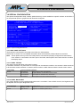
╔══════════════════════════════════════════════════════════════════════════════╗
║
System Bios Setup - Utility v5.3
║
║
(C) 2005 General Software, Inc. All rights reserved
║
╠═════════════════════════════╤════════════════════════════════════════════════╣
║
│
║
║
│
║
║
│
>Basic CMOS Configuration
║
║ System Information:
│
Features Configuration
║
║
│
Onboard Devices Configuration
║
║ Model: PIP8 (0xA1, 0x81)
│
Special Configuration
║
║ PLD:
Revision 0x00
│
PnP Configuration
║
║
│
Shadow Configuration
║
║ BIOS Version: V1.40
│
Save CMOS to nonvolatile Flash
║
║ Build Date:
01/17/08
│
Load CMOS from nonvolatile Flash
║
║ BIOS No:
MEV-10100-081 │
Reset CMO to last known values
║
║
│
Reset CMOS to factory defaults
║
║ LAN:
Dev 0x1209 R 0x10 │
Write to CMOS and Exit
║
║ MAC Addr: 00:60:C2:10:XX:XX │
Exit without changing CMOS
║
║
│
║
║
│
║
║
│
║
╠═════════════════════════════╧════════════════════════════════════════════════╣
║
↑/↓/<Tab> to select. <Esc> to continue (no save)
║
║
www.gensw.com
║
╚══════════════════════════════════════════════════════════════════════════════╝
2008 by MPL AG
1
MEH-10106-181 Rev. D
PIP8
H ig h -Te c h • M a d e in Sw itze rla n d
SYSTEM BIOS USER MANUAL
TABLE OF CONTENTS
1 INTRODUCTION.............................................................................................................6
1.1 BIOS FEATURES..................................................................................................................6
1.2 ABOUT THIS MANUAL.........................................................................................................6
1.3 MANUAL REVISIONS............................................................................................................7
1.3.1 RELATED PRODUCTS..................................................................................................7
1.3.2 REVISION HISTORY.....................................................................................................7
1.4 RELATED DOCUMENTATION..............................................................................................7
2 HARDWARE CONFIGURATION....................................................................................8
2.1 INTERRUPTS (IRQs).............................................................................................................8
2.2 MEMORY...............................................................................................................................9
2.3 I/O.........................................................................................................................................10
2.4 EXAMPLE CONFIGURATION.............................................................................................11
2.5 GRAPHICS CONFIGURATION...........................................................................................12
2.5.1 INTERNAL GRAPHICS CONTROLLER.......................................................................12
2.5.2 FLAT PANEL DISPLAY (LVDS) INTERFACE..............................................................12
2.5.2.1 DISPLAY TIMINGS...............................................................................................................12
2.5.2.2 BACKLIGHT INVERTER TYPES..........................................................................................13
2.5.2.3 BIOS CONFIGURATION......................................................................................................13
2.5.2.3.1 PANEL FITTING...........................................................................................................13
2.5.2.3.2 PANEL BACKLIGHT....................................................................................................14
2.5.2.3.3 BRIGHTNESS LEVEL..................................................................................................14
3 BIOS..............................................................................................................................15
3.1 BIOS UPDATE.....................................................................................................................15
3.2 BOOT SCREEN...................................................................................................................16
3.2.1 BIOS RELEASE INDEX................................................................................................16
3.2.2 PCI DEVICES...............................................................................................................16
3.2.3 MASS STORAGE DEVICES........................................................................................17
3.3 ENTERING BIOS SETUP....................................................................................................17
3.4 MAIN BIOS SETUP SCREEN..............................................................................................18
3.4.1 SYSTEM INFORMATION.............................................................................................18
3.4.1.1 MODEL.................................................................................................................................18
3.4.1.2 PLD.......................................................................................................................................18
3.4.1.3 BIOS VERSION....................................................................................................................18
3.4.1.4 BUILD DATE.........................................................................................................................18
3.4.1.5 BIOS NO...............................................................................................................................18
3.4.1.6 LAN.......................................................................................................................................18
3.4.1.7 MAC ADDR...........................................................................................................................18
3.4.2 MAIN SETUP MENU....................................................................................................19
3.4.2.1 SAVE CMOS TO NONVOLATILE FLASH............................................................................19
3.4.2.2 LOAD CMOS FROM NONVOLATILE FLASH......................................................................19
3.4.2.3 RESET CMOS TO LAST KNOWN VALUES........................................................................19
3.4.2.4 RESET CMOS TO FACTORY DEFAULTS..........................................................................19
3.4.2.5 WRITE TO CMOS AND EXIT...............................................................................................19
3.4.2.6 EXIT WITHOUT CHANGING CMOS....................................................................................19
3.5 BASIC CMOS CONFIGURATION.......................................................................................20
3.5.1 DRIVE ASSIGNMENT ORDER....................................................................................20
3.5.2 FLOPPY DRIVE TYPES...............................................................................................20
3.5.3 BOOT ORDER.............................................................................................................21
3.5.4 ATA DRIVE ASSIGNMENT..........................................................................................21
3.5.5 GENERAL SETTINGS..................................................................................................22
3.6 FEATURES CONFIGURATION...........................................................................................23
3.6.1 ACPI 1.0.......................................................................................................................23
2008 by MPL AG
2
MEH-10106-181 Rev. D
PIP8
H ig h -Te c h • M a d e in Sw itze rla n d
SYSTEM BIOS USER MANUAL
3.6.2 SYSTEM MANAGEMENT MODE................................................................................23
3.6.3 GRAPHICAL POST......................................................................................................24
3.6.4 PRIMARY ATA MODE..................................................................................................24
3.6.5 SECONDARY ATA MODE...........................................................................................24
3.6.6 CONSOLE REDIRECTION..........................................................................................24
3.6.7 USB HID.......................................................................................................................25
3.6.8 USB MASS STORAGE.................................................................................................25
3.7 ONBOARD DEVICES CONFIGURATION...........................................................................26
3.7.1 SERIAL PORT 1...........................................................................................................26
3.7.2 SERIAL PORT 2...........................................................................................................27
3.7.3 SERIAL PORT 3...........................................................................................................27
3.7.4 SERIAL PORT 4...........................................................................................................28
3.7.5 PARALLEL PORT........................................................................................................28
3.7.6 FLOPPY CONTROLLER..............................................................................................29
3.7.7 PS/2 MOUSE................................................................................................................29
3.8 SPECIAL CONFIGURATION...............................................................................................30
3.8.1 LVDS PANEL SETTINGS.............................................................................................30
3.8.1.1 PANEL FITTING...................................................................................................................30
3.8.1.2 PANEL BACKLIGHT.............................................................................................................30
3.8.1.3 BRIGHTNESS LEVEL...........................................................................................................31
3.8.2 PXE BOOT ROM..........................................................................................................31
3.8.3 MASS STORAGE.........................................................................................................31
3.8.4 PC104 MEM BASE.......................................................................................................31
3.8.5 CPU FREQUENCY......................................................................................................32
3.8.6 AC97 AUDIO................................................................................................................32
3.8.7 MIN UPS CHARGE TO BOOT.....................................................................................32
3.9 SHADOW RAM CONFIGURATION.....................................................................................33
3.10 PLUG-N-PLAY CONFIGURATION....................................................................................34
3.10.1 GENERAL PNP CONFIGURATION...........................................................................34
3.10.2 PNP IRQ CONFIGURATION......................................................................................35
3.10.3 PNP DMA CONFIGURATION....................................................................................35
4 NONVOLATILE BIOS SETUP......................................................................................36
4.1 OVERVIEW..........................................................................................................................36
4.2 USAGE.................................................................................................................................36
4.2.1 SAVE CMOS TO NONVOLATILE FLASH....................................................................37
4.2.2 LOAD CMOS FROM NONVOLATILE FLASH..............................................................37
4.2.2.1 CMOS LOAD ERROR...........................................................................................................37
5 USB BOOT....................................................................................................................38
5.1 OVERVIEW..........................................................................................................................38
5.2 BIOS SETTINGS..................................................................................................................38
6 NETWORK BOOT (PXE)..............................................................................................40
6.1 PXE CONFIGURATION.......................................................................................................40
6.2 CHANGING THE CONFIGURATION...................................................................................40
6.3 BOOTING FROM NETWORK..............................................................................................40
7 COPYRIGHT.................................................................................................................44
8 DISCLAIMER................................................................................................................44
9 TRADEMARKS.............................................................................................................44
2008 by MPL AG
3
MEH-10106-181 Rev. D
PIP8
H ig h -Te c h • M a d e in Sw itze rla n d
SYSTEM BIOS USER MANUAL
10 SUPPORT...................................................................................................................44
2008 by MPL AG
4
MEH-10106-181 Rev. D
PIP8
H ig h -Te c h • M a d e in Sw itze rla n d
SYSTEM BIOS USER MANUAL
TABLE OF FIGURES
Figure 1: Memory Map.......................................................................................................................9
Figure 2: BIOS Release Index.........................................................................................................17
Figure 3: PCI Device Table..............................................................................................................17
Figure 4: Mass Storage Device Table..............................................................................................18
Figure 5: CDROM Device Table......................................................................................................18
Figure 6: Enter Setup Message.......................................................................................................18
Figure 7: Main BIOS Setup Screen..................................................................................................19
Figure 8: Basic CMOS Configuration Screen..................................................................................21
Figure 9: Features Configuration Screen.........................................................................................24
Figure 10: Onboard Devices Configuration Screen.........................................................................27
Figure 11: Special Configuration Screen.........................................................................................31
Figure 12: Shadow RAM Configuration Screen...............................................................................34
Figure 13: Plug-N-Play Configuration Screen..................................................................................35
Figure 14: Main BIOS Setup Menu..................................................................................................37
Figure 15: Save CMOS Dialog Box.................................................................................................38
Figure 16: Load CMOS Dialog Box..................................................................................................38
Figure 17: Load CMOS Error Dialog................................................................................................38
Figure 18: Features Configuration for USB Boot.............................................................................39
Figure 19: Basic CMOS Configuration for USB Boot.......................................................................40
Figure 20: PXE Boot Message........................................................................................................41
2008 by MPL AG
5
MEH-10106-181 Rev. D
PIP8
H ig h -Te c h • M a d e in Sw itze rla n d
SYSTEM BIOS USER MANUAL
1 INTRODUCTION
1.1 BIOS FEATURES
The PIP8 BIOS V1.40 supports the following standards and key features:
•
•
•
•
•
•
•
ACPI 1.0
Plug'n'Play
USB Boot (Floppy disk, CD-ROM, Hard disk)
USB Legacy Keyboard and Mouse
PXE Network Boot
Console Redirection over Serial Port
MPL UPS-1
1.2 ABOUT THIS MANUAL
This manual provides all the information necessary to configure the PIP8 BIOS. The manual is written for
technical personnel. It is recommended to use this manual in combination with the PIP8 User Manual.
NOTE
It is strongly recommended to read the PIP8 User Manual, the
PIP8 Technical Reference Manual and also this manual before the PIP8 is switched on.
2008 by MPL AG
6
MEH-10106-181 Rev. D
PIP8
H ig h -Te c h • M a d e in Sw itze rla n d
SYSTEM BIOS USER MANUAL
1.3 MANUAL REVISIONS
1.3.1 RELATED PRODUCTS
Manual
Revision
A
B
C
D
Related To
PIP8 BIOS V1.20
PIP8 BIOS V1.22
PIP8 BIOS V1.30
PIP8 BIOS V1.40
1.3.2 REVISION HISTORY
Manual
Revision
A
B
2006-04-28
2006-07-07
C
2006-10-31
D
2008-01-17
Date
Description
Initial release of this document.
Reflect BIOS V1.22 features:
- IRQ12 available for PC/104 if no PS/2 mouse connected
- Added boot delay support for UPS-1 option
- Graphics driver shows nonpresent output devices
- PCI Enumeration: Added handling for second PCI-to-PCI bridge
- Setup Menu handling improved
Reflect BIOS V1.30 features:
- PS/2 Mouse port configurable
- LVDS panel backlight brightness adjustable in BIOS setup
- Internal graphics controller disableable
- Panel type 6 timing optimized
- Bugfix ATA cable detection
Reflect BIOS V1.40 features:
- PXE: Updated PXE binary (v1.2.70)
- Graphics: Updated VGA BIOS (build 1270)
- Graphics: Backlight Brightness Control fixed
- Graphics: Panel timings and inverter types defined / optimized
- PnP nodes for mouse and floppy dynamically
- Enhanced support for MWDMA modes and Compact Flash
- ISA Refresh disabled
- Setup Screen / POST messages enhancements
1.4 RELATED DOCUMENTATION
The following documents are related to this manual. For detailed Information about a specific PIP8 feature or
setting please refer to these additional manuals.
Reference
[1]
[2]
2008 by MPL AG
Description
PIP8 User Manual
PIP8 Technical Reference Manual
MPL AG:
MPL AG:
7
Available from
http://www.mpl.ch/t2440.html
http://www.mpl.ch/t2440.html
MEH-10106-181 Rev. D
PIP8
SYSTEM BIOS USER MANUAL
H ig h -Te c h • M a d e in Sw itze rla n d
2 HARDWARE CONFIGURATION
2.1 INTERRUPTS (IRQs)
The standard PC AT architecture is limited to 16 Interrupts (IRQs). The following table shows the typical usage
of the available interrupt lines on the PIP8.
Please consult this table before changing IRQ assignments of devices in the BIOS or adding PC/104 expansion
cards in order to avoid conflicts and to make sure that there will be sufficient IRQs available.
The PIP8 standard configuration uses all but two interrupts (5 and 11). IRQ 12 is also available if the following
two conditions are met:
•
•
'PS/2 Mouse' (refer to section 3.7.7) is set to 'Disabled' or it is set to 'Auto' and no PS/2 mouse is
connected
'UsbHid' (refer to section 3.6.7) is disabled
Additional interrupts can be made available by disabling onboard devices. Onboard devices that can be
configured to use different interrupts are marked “Configurable” in the table below.
IRQ
0
1
2
3
4
5
6
7
8
9
10
11
12
13
14
15
Usage
System Timer
Keyboard
Cascade
Serial Port 2 / Serial Port 4
Serial Port 1 / Serial Port 3
Not used
Floppy Disk Controller
Parallel Port
Real Time Clock (RTC)
PCI Devices
PCI Devices
Not used
PS/2 Mouse
Floating Point Unit (FPU)
Primary ATA Channel
Secondary ATA Channel
Remarks
PIP8 default configuration
Not available
Not available
Not available
Configurable / Available for PC/104
Used
Configurable / Available for PC/104
Used
Configurable / Available for PC/104
Available
Available for PC/104
Used
Configurable / Available for PC/104
Used
Not available
Not available
Not available
Configurable / Available for PC/104
Available
Available for PC/104 if PS/2 mouse disabled and UsbHid disabled
Not available
Not available
Not available
For a PC/104 card configuration example, please refer to section 2.4.
2008 by MPL AG
8
MEH-10106-181 Rev. D
PIP8
SYSTEM BIOS USER MANUAL
H ig h -Te c h • M a d e in Sw itze rla n d
2.2 MEMORY
PC/104 (ISA) and PC/104-Plus (PCI) add-on cards may require a certain amount of memory for installing their
option ROMs or they have onboard memory that needs to be mapped into the system memory space.
The memory area used for this purpose is limited to 000C0000h – 000DFFFFh.
Note: This area is 16kB (4000h) granular if used as shadow RAM for option ROMs. This means that although
an option ROM may occupy only 2kB (800h), the rest of this 16kB area cannot be used by other
devices. This implies that option ROMs always start and end on 16kB boundaries.
The area C0000h – CFFFFh is used by the VGA BIOS and is therefore not available for other devices.
The system BIOS is located at E0000h – FFFFFh (128kB).
The PXE Boot ROM can be disabled in BIOS setup (please refer to 3.8.2) to free up memory ranges which can
be used for other purposes. Option ROMs are installed starting at 0D0000h.
Fig. 1 shows the memory map with different configurations of the PXE option ROM included in the system
BIOS.
PXE ROM e nable d
PXE ROM dis abled
Syste m
BIOS
Syste m
BIOS
E0000h
E0000h
available
DC000h
PXE
ROM
D8000h
DC000h
16kB
each
available
D8000h
available
D4000h
D4000h
available
VGA
BIOS
D0000h
D0000h
CC000h
CC000h
C8000h
VGA
BIOS
C8000h
C4000h
C4000h
C0000h
C0000h
Figure 1: Memory Map
The free ranges in the figure above can be used as ISA memory for PC/104 cards (see section 3.8.4) or for
additional option ROMs of add-on cards (see section 3.9).
For a PC/104 card configuration example, please refer to section 2.4.
2008 by MPL AG
9
MEH-10106-181 Rev. D
PIP8
H ig h -Te c h • M a d e in Sw itze rla n d
SYSTEM BIOS USER MANUAL
2.3 I/O
Input/Output space is required by most PC/104 cards. The table below is an overview of the PIP8's I/O space
usage from 0000h to 03FFh, which is the important range for PC/104 cards.
“Configurable” devices can be set up to use a different I/O range, or can be disabled completely.
I/O range
03F8h – 03FFh
03F7h – 03F7h
03F6h – 03F6h
03F0h – 03F5h
03E8h – 03EFh
03C0h – 03DFh
03B0h – 03BBh
0378h – 037Fh
0376h – 0376h
0338h – 033Fh
02F8h – 02FFh
02E8h – 02EFh
0278h – 027Fh
0238h – 023Fh
0228h – 022Fh
0220h – 0227h
01F0h – 01F7h
0170h – 0177h
0000h – 00FFh
Usage
Serial port
Floppy disk controller
Primary ATA channel
Floppy disk controller
Serial port
VGA
VGA
Parallel port
Secondary ATA channel
Serial port
Serial port
Serial port
Parallel port
Serial port
Serial port
Serial port
Primary ATA channel
Secondary ATA channel
Various system devices
Remarks
Configurable
Configurable
Configurable
Configurable
Configurable
Configurable
Configurable
Configurable
Configurable
Configurable
Configurable
Configurable
PIP8 default configuration
Used
Used
Not available
Used
Used
Not available
Not available
Used
Not available
Available
Used
Used
Available
Available
Available
Available
Not available
Not available
Not available
This leads to the following consecutive I/O ranges that can be used by PC/104 cards on a PIP8 with default
configuration:
•
•
•
•
•
100h – 16Fh
180h – 1EFh
200h – 2DFh
300h – 370h
380h – 3AFh
For a PC/104 card configuration example, please refer to section 2.4.
2008 by MPL AG
10
MEH-10106-181 Rev. D
PIP8
H ig h -Te c h • M a d e in Sw itze rla n d
SYSTEM BIOS USER MANUAL
2.4 EXAMPLE CONFIGURATION
The following is an example of how to configure a PC/104 add-on card. These cards commonly require manual
configuration and can cause problems if they are not configured properly.
Note: PC/104 cards are ISA based, while PC/104-Plus cards are PCI based. PC/104-Plus cards generally do
not require manual configuration.
In this example, a Softing CAN-AC2-104 CAN card (PC/104) is used.
Step 1 – Resources required by PC/104 card
•
Check the resource requirements of the add-on card. Refer to the card's User Manual for the
requirements. The CAN-AC2-104 board has the following requirements:
– I/O range:
4 Byte area between 0000h and 03FFh
– Memory range:
16kByte area between C8000h and F7FFFh
– IRQ channel:
One IRQ
Step 2 – Define card configuration
•
Choose a resource configuration that is not conflicting with other system devices or installed cards.
After checking with the available resources of the PIP8, we choose the following values:
– I/O range:
240h
(check section 2.3 for available I/O ranges)
– Memory range:
DC000h
(check section 2.2 for available memory ranges)
– IRQ channel:
5
(check section 2.1 for available IRQs)
Note: Only the memory range needs to be configured in the BIOS setup! I/O range and
interrupt channel do not need to be configured in the BIOS.
•
Configure the selected I/O range on the card by setting the DIP switch accordingly. The memory
and IRQ configurations for this card are done by software. However, other types of cards may have
jumpers or DIP switches for memory and/or IRQ configuration. If so, these must be configured
correctly.
Step 3 – Configure BIOS
•
I/O
We chose an I/O range that is not used by any other device, therefore no configuration is needed.
•
Memory
This card does not have an Option ROM, therefore Shadow memory must be disabled for the
configured memory range.
•
Set up 'PC104 Mem Base Addr' and 'PC104 Mem Size' according to the chosen configuration.
See section 3.8.4 for further information.
– PC/104 MEM Base Addr:
DC000h
– PC/104 MEM Length:
16k
•
Disable Shadow Memory for the selected memory range. See section 3.9 for further
information.
– Shadow 16KB ROM at DC00: Disabled
•
IRQ
We chose an IRQ that is not used by any other device, therefore no configuration is needed.
Step 4 – Use the card
•
The PIP8 BIOS is now properly configured for the use of the CAN-AC2-104 card. After the
installation of all necessary software and/or drivers, the card is operational.
2008 by MPL AG
11
MEH-10106-181 Rev. D
PIP8
SYSTEM BIOS USER MANUAL
H ig h -Te c h • M a d e in Sw itze rla n d
2.5 GRAPHICS CONFIGURATION
2.5.1 INTERNAL GRAPHICS CONTROLLER
The integrated graphics controller can be disabled
Technical Reference Manual for further information).
SW4-1
OFF
ON
with
DIP
switch
4
(please
refer
to
the
Internal Graphics Controller
Internal Graphics Controller Enabled
Internal Graphics Controller Disabled
2.5.2 FLAT PANEL DISPLAY (LVDS) INTERFACE
The PIP8 features an internal LVDS connector for a flat panel display.
More information about the LVDS connector can be found in the Technical Reference Manual.
NOTE
All configuration options in this chapter are used for the LVDS port only. If the monitor is
connected to the DVI-I port of the PIP8 and the internal LVDS port is not used, these options
should not be modified.
2.5.2.1 DISPLAY TIMINGS
The timings for different flat panel types are
Technical Reference Manual for further information).
set
with
DIP
switch
4
(please
refer
to
the
NOTE
If a valid panel type is selected, the DVI-I port of the PIP8 will be disabled and cannot be used
in environments that do not have an Intel Graphics driver (e.g. POST, DOS).
In BIOS V1.40, the following panel timings are implemented:
SW4-5 SW4-6 SW4-7 SW4-8
ON
ON
ON
ON
OFF
ON
ON
ON
ON
OFF
ON
ON
OFF
OFF
ON
ON
ON
ON
OFF
ON
OFF
ON
OFF
ON
ON
OFF
OFF
ON
OFF
OFF
OFF
ON
ON
ON
ON
OFF
OFF
ON
ON
OFF
ON
OFF
ON
OFF
OFF
OFF
ON
OFF
ON
ON
OFF
OFF
OFF
ON
OFF
OFF
ON
OFF
OFF
OFF
OFF
OFF
OFF
OFF
2008 by MPL AG
Panel type
1
2
3
4
5
6
7
8
9
10
11
12
13
14
15
16
Resolution
640 x 480
800 x 600
1024 x 768
1280 x 1024
1366 x 768
1920 x 1080
1024 x 768
800 x 600
(reserved)
(reserved)
(reserved)
(reserved)
(reserved)
(reserved)
(reserved)
(reserved)
12
Mode information
Single channel, data format 1
Single channel, data format 1
Single channel, data format 1
Dual channel, data format 1
Single channel, data format 0
Dual channel, data format 1
Single channel, data format 0
Single channel, data format 0
Not used – LVDS port disabled
Not used – LVDS port disabled
Not used – LVDS port disabled
Not used – LVDS port disabled
Not used – LVDS port disabled
Not used – LVDS port disabled
Not used – LVDS port disabled
Not used – LVDS port disabled (default)
MEH-10106-181 Rev. D
PIP8
SYSTEM BIOS USER MANUAL
H ig h -Te c h • M a d e in Sw itze rla n d
2.5.2.2 BACKLIGHT INVERTER TYPES
The type of backlight inverter used for the flat panel is set with DIP switch 4 (please refer to the
Technical Reference Manual for further information).
This setting defines the voltage range that controls backlight intensity.
WARNING
If the backlight brightness is controlled via the PIP8, the backlight inverter type must be
configured correctly!
Failure to do so may cause damage to the inverter and/or the panel backlight.
In BIOS V1.40, the following inverter types are implemented:
SW4-2
OFF
ON
OFF
ON
OFF
ON
OFF
ON
SW4-3
OFF
OFF
ON
ON
OFF
OFF
ON
ON
SW4-4
OFF
OFF
OFF
OFF
ON
ON
ON
ON
Inverter type
Type 1
Type 2
Type 3
Type 4
Type 5
Type 6
Type 7
Type 8
Voltage range
0 Volt – 5 Volt
5 Volt – 0 Volt
1.8 Volt – 0 Volt
0 Volt – 2 Volt
(reserved)
(reserved)
(reserved)
(reserved)
Min. brightness
0 Volt
5 Volt
1.8 Volt
0 Volt
not defined
not defined
not defined
not defined
Max. brightness
5 Volt
0 Volt
0 Volt
2 Volt
not defined
not defined
not defined
not defined
2.5.2.3 BIOS CONFIGURATION
The flat panel related BIOS settings are located in the Special Configuration Menu (refer to section 3.8).
Note:
These options are only active if a LVDS panel is connected and properly configured via DIP switches.
If the monitor is connected to the DVI-I port of the PIP8, these options are inactive and do not affect
the display output.
2.5.2.3.1 PANEL FITTING
This option controls the fitting of the panel contents.
If the native resolution of a panel does not correspond to the software resolution, the contents is either stretched
to fit the native screen resolution or centered, which results in a black frame around the actual screen content.
Panel Fitting is only used in environments without Intel Graphics driver installed (e.g. POST screen, DOS). If an
operating system with Intel Graphics driver is started, this setting can be overridden by the driver.
Panel Fitting
default
2008 by MPL AG
Controls panel fitting behavior
All Stretched
Always fit the screen size (default)
Gfx Stretched
Graphics Modes are stretched to fit the screen
Text Stretched
Text modes are stretched to fit the screen
All Centered
Both Graphics and Text modes are centered
13
MEH-10106-181 Rev. D
PIP8
H ig h -Te c h • M a d e in Sw itze rla n d
SYSTEM BIOS USER MANUAL
2.5.2.3.2 PANEL BACKLIGHT
This option selects whether the LVDS panel backlight brightness is controlled by BIOS setting or by other
means (Hardware up/down switches or application software control).
When set to 'HW/App Control', the backlight can be dimmed by connecting UP and DOWN switches / buttons to
Panel Dimming connector J27 (please refer to the Technical Reference Manual for further information).
Panel Backlight
default
Defines backlight brightness control
HW/App Control
Brightness controlled by hardware or application
BIOS Control
Brightness controlled by BIOS setup
2.5.2.3.3 BRIGHTNESS LEVEL
This option controls the brightness level of the panel backlight, if 'Panel Backlight' is set to 'BIOS Setup'. The
brightness can be adjusted in 5% increments.
Note:
Modifying this option changes the backlight brightness instantly. However, it is still required to write
the settings to CMOS when leaving the BIOS setup. Otherwise, the previous brightness setting will be
used after leaving the setup.
Brightness Level
default
2008 by MPL AG
Selects brightness level of the backlight, if “BIOS Control” is selected
Minimal
Minimal brightness level
5%
5% brightness level
10%
10% brightness level
...
...
...
[5% increments]
...
...
95%
95% brightness level
100%
100% brightness level
14
MEH-10106-181 Rev. D
PIP8
H ig h -Te c h • M a d e in Sw itze rla n d
SYSTEM BIOS USER MANUAL
3 BIOS
3.1 BIOS UPDATE
The system BIOS of the PIP8 resides in a FLASH memory. Therefore BIOS updating with an additional utility is
easily possible.
For BIOS updating, download the Windows executable program file from the MPL AG homepage www.mpl.ch.
This file creates a bootable floppy disk including all the files necessary to update the BIOS.
1.
2.
3.
4.
Download BIOS update file suitable for your PIP8.
Execute the BIOS update file to create the bootable BIOS update disk.
Boot your PIP8 with the BIOS update disk.
Follow the instructions on the screen. You can choose to save the current BIOS version to the disk
as a backup in case you want to revert the update.
5. BIOS update starts and informs you of the progress.
6. Power down the system after the BIOS update.
The new BIOS takes control the next time you start up your PIP8.
CAUTION
If something fails (e.g., loss of power) during BIOS updating (especially after erasing the
FLASH memory) and the utility can not terminate properly, the PIP8 will no longer have a
valid BIOS!
In these cases, contact MPL AG to start up the system again.
If your system is not equipped with a floppy drive, use one of the following ways to update the BIOS:
1. External USB floppy drive
The BIOS update disk can be booted with an USB floppy drive.
Please refer to section 5 for more information about booting from USB devices.
2. USB Flash Drive
An USB flash drive (USB pen drive, USB memory stick) which contains a bootable DOS partition
can be used to do the BIOS update. Copy the BIOS update files to the bootable USB flash drive
and boot it. The BIOS update will start from the DOS prompt.
Please refer to section 5 for more information about booting from USB devices.
3. CD ROM drive (external USB drive or internal ATA drive)
If your system has a CD ROM drive, the BIOS update disk can be used as boot image to create a
bootable CD ROM.
4. Hard Disk drive (external USB drive or internal ATA drive)
If your system hard disk contains a DOS partition, you can start the BIOS update from there.
If your system hard disk does not contain a DOS partition, you can temporarily install a different
hard drive that boots a DOS. This hard drive can either be connected to one of the P-ATA / S-ATA
ports or externally to the USB port.
5. Network (PXE) boot
It is possible to boot the BIOS update disk via network. The boot server in the network must be
configured to provide an image created from the BIOS update disk as boot file.
2008 by MPL AG
15
MEH-10106-181 Rev. D
PIP8
H ig h -Te c h • M a d e in Sw itze rla n d
SYSTEM BIOS USER MANUAL
3.2 BOOT SCREEN
At POST (Power On Self Test), various information about the system configuration is displayed.
3.2.1 BIOS RELEASE INDEX
The BIOS release index and CPU information are shown during POST. The CPU signature (06D8) contains
family (6), model (D) and stepping (8) information of the installed processor, and the actual CPU speed is
displayed as well. This information changes according to the installed processor type.
The PIP type (PIP8) is displayed along with the BIOS version (V1.40) and BIOS identification number
(MEV-10100-081).
The following figure shows how this information is displayed, with the 1000MHz Celeron-M CPU as example:
MPL PIP8 BIOS V1.40 – Celeron-M (06D8) at 1000MHz
MEV-10100-081
Figure 2: BIOS Release Index
3.2.2 PCI DEVICES
At POST, the PCI devices installed in the system are listed. The figure below shows the PCI devices present on
the PIP8 board.
NOTE: All additional PC/104+ and/or PCI devices installed in the system will appear on bus 02 and above.
PCI Device Table.
Bus Dev Func VendID DevID Class
Irq
00 00 00
8086
3580 Host Bridge
00 00 01
8086
3584 System
00 00 03
8086
3485 System
00 02 00
8086
3582 VGA Display
10
00 02 01
8086
3582 Display
00 1C 00
8086
25AE PCI-to-PCI Bridge
00 1D 00
8086
25A9 Serial Bus
10
00 1D 01
8086
25AA Serial Bus
10
00 1D 04
8086
25AB System
00 1D 05
8086
25AC IRQ Controller
00 1D 07
8086
25AD Serial Bus
10
00 1E 00
8086
244E PCI-to-PCI Bridge
00 1F 00
8086
25A1 ISA Bridge
00 1F 01
8086
25A2 IDE Controller
14
00 1F 03
8086
25A4 Serial Bus
10
00 1F 05
8086
25A6 Audio
10
01 01 00
8086
1076 Ethernet
9
02 00 00
104C
8025 Firewire
10
02 06 00
100B
0021 ISA Bridge
Figure 3: PCI Device Table
2008 by MPL AG
16
MEH-10106-181 Rev. D
PIP8
H ig h -Te c h • M a d e in Sw itze rla n d
SYSTEM BIOS USER MANUAL
3.2.3 MASS STORAGE DEVICES
The following example shows how mass storage devices are listed.
CDROM Device(s):
ATA 2: Pioneer DVD-ROM ATAPIModel D E1.21
ATA Device(s):
ATA 0: HTS424040M9AT00
MA20A71A
ATA 1: STI Flash Drive
Rev 1.1
STI
MPA2412Q2GW4T12
0E202022102934
Figure 4: Mass Storage Device Table
Each installed ATA device is listed with device location (1st column), device name (2nd column), firmware revision
(3rd column) and model no. (4th column).
The table is divided into CDROM Device(s) and ATA Device(s).
CDROM devices are optical devices such as CD-ROM drives, DVD drives etc. Additionally, if the BIOS is
configured to boot from a CD-ROM drive, a message indicating the search for a bootable image on the disk
appears, as follows:
CDROM Device(s):
ATA 2: Pioneer DVD-ROM ATAPIModel D E1.21
Searching for El Torito Bootable Image... Found a bootable image.
Figure 5: CDROM Device Table
Note: The "Searching for El Torito Bootable Image" message appears also with USB CD-ROM drives.
However, they are not listed in the device table. The table lists only ATA devices.
3.3 ENTERING BIOS SETUP
The BIOS Setup is entered by pressing the <DEL> key at POST, indicated by the following message:
Hit <Del> if you want to run SETUP.
Figure 6: Enter Setup Message
If the console is being redirected, the key combination <CTRL>+<C> must be sent from the serial terminal
program for entering the BIOS Setup. Please refer to section 3.6.6 for more information about Console
Redirection.
2008 by MPL AG
17
MEH-10106-181 Rev. D
PIP8
SYSTEM BIOS USER MANUAL
H ig h -Te c h • M a d e in Sw itze rla n d
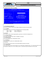
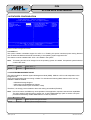
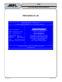
3.4 MAIN BIOS SETUP SCREEN
╔══════════════════════════════════════════════════════════════════════════════╗
║
System Bios Setup - Utility v5.3
║
║
(C) 2005 General Software, Inc. All rights reserved
║
╠═════════════════════════════╤════════════════════════════════════════════════╣
║
│
║
║
│
║
║
│
>Basic CMOS Configuration
║
║ System Information:
│
Features Configuration
║
║
│
Onboard Devices Configuration
║
║ Model: PIP8 (0xA1, 0x81)
│
Special Configuration
║
║ PLD:
Revision 0x00
│
PnP Configuration
║
║
│
Shadow Configuration
║
║ BIOS Version: V1.40
│
Save CMOS to nonvolatile Flash
║
║ Build Date:
01/17/08
│
Load CMOS from nonvolatile Flash
║
║ BIOS No:
MEV-10100-081 │
Reset CMO to last known values
║
║
│
Reset CMOS to factory defaults
║
║ LAN:
Dev 0x1209 R 0x10 │
Write to CMOS and Exit
║
║ MAC Addr: 00:60:C2:10:XX:XX │
Exit without changing CMOS
║
║
│
║
║
│
║
║
│
║
╠═════════════════════════════╧════════════════════════════════════════════════╣
║
↑/↓/<Tab> to select. <Esc> to continue (no save)
║
║
www.gensw.com
║
╚══════════════════════════════════════════════════════════════════════════════╝
Figure 7: Main BIOS Setup Screen
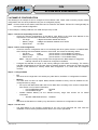
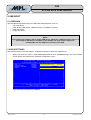
3.4.1 SYSTEM INFORMATION
The left side of the main setup screen displays detailed information about the system.
3.4.1.1 MODEL
The hardware revision of the board is displayed after the model type (PIP8):
(0xA0, 0x81)
(0xA1, 0xB1)
PIP8-11 PCB Rev. B
PIP8-C1 PCB Rev. B
3.4.1.2 PLD
The software revision of the Programmable Logic Device on the PIP8 is displayed here.
3.4.1.3 BIOS VERSION
This reflects the BIOS version which is installed on the PIP8.
3.4.1.4 BUILD DATE
This is the build date of the installed BIOS version.
3.4.1.5 BIOS NO
This is the product number of the installed BIOS version.
3.4.1.6 LAN
This is the device ID and revision of the onboard Network Interface Controller.
3.4.1.7 MAC ADDR
The unique Media Access Control address of the onboard NIC is displayed here. It is six bytes long and the first
three bytes are always 00:60:C2 for MPL products. The last three bytes are different on every PIP8.
2008 by MPL AG
18
MEH-10106-181 Rev. D
PIP8
H ig h -Te c h • M a d e in Sw itze rla n d
SYSTEM BIOS USER MANUAL
3.4.2 MAIN SETUP MENU
The right side of the main setup screen contains the menu used to navigate through the BIOS setup options.
The menu entries will be discussed in detail below.
3.4.2.1 SAVE CMOS TO NONVOLATILE FLASH
This feature writes the current BIOS settings to the Flash. Please refer to section 4 for detailed information
about nonvolatile BIOS setup.
3.4.2.2 LOAD CMOS FROM NONVOLATILE FLASH
Use this feature to manually read the BIOS settings from the Flash. Please refer to section 4 for detailed
information about nonvolatile BIOS setup.
3.4.2.3 RESET CMOS TO LAST KNOWN VALUES
This option discards changes made during this BIOS Setup session by reloading the values from the CMOS
RAM.
3.4.2.4 RESET CMOS TO FACTORY DEFAULTS
This option resets the BIOS settings to their default values.
3.4.2.5 WRITE TO CMOS AND EXIT
This option is used leave the BIOS setup and write the current BIOS settings to the CMOS RAM. The system
will reboot automatically.
3.4.2.6 EXIT WITHOUT CHANGING CMOS
Use this option to leave the BIOS setup without saving the settings to CMOS RAM.
2008 by MPL AG
19
MEH-10106-181 Rev. D
PIP8
H ig h -Te c h • M a d e in Sw itze rla n d
SYSTEM BIOS USER MANUAL
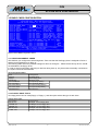
3.5 BASIC CMOS CONFIGURATION
╔══════════════════════════════════════════════════════════════════════════════╗
║
System BIOS Setup - Basic CMOS Configuration
║
║
(C) 2005 General Software, Inc. All rights reserved
║
╠═══════════════════════════╤════════════════════╤═════════════════════════════╣
║ DRIVE ASSIGNMENT ORDER:
│ Date:>Apr 15, 2008 │ Typematic Delay : 250 ms
║
║ Drive A: Floppy 0
│ Time: 20 : 21 : 12 │ Typematic Rate
: 30 cps
║
║ Drive B: (None)
│ NumLock: Enabled │ Seek at Boot
: None
║
║ Drive C: ATA 0/Pri Master ├────────────────────┤ Show "Hit Del"
: Enabled ║
║ Drive D: ATA 2/Sec Master │ BOOT ORDER:
│ Config Box
: Enabled ║
║ Drive E: (None)
│ Boot 1st: Drive A: │ F1 Error Wait
: Enabled ║
║ Drive F: (None)
│ Boot 2nd: CDROM
│ Parity Checking : (Unused) ║
║ Drive G: (None)
│ Boot 3rd: Drive C: │ Memory Test Tick : Disabled ║
║ Drive H: (None)
│ Boot 4th: (None)
│ Debug Breakpoints: (Unused) ║
║ Drive I: (None)
│ Boot 5th: (None)
│ Debugger Hex Case: Upper
║
║ Drive J: (None)
│ Boot 6th: (None)
│ Memory Test : StdLo FastHi ║
║ Drive K: (None)
├────────────────────┴─────────────────┬───────────╢
║ (Loader): (Unused)
│ ATA DRV ASSIGNMENT: Sect Hds Cyls │ Memory
║
╟───────────────────────────┤ ATA 0: 3 = AUTOCONFIG, LBA
│ Base:
║
║ FLOPPY DRIVE TYPES:
│ ATA 1: 3 = AUTOCONFIG, LBA
│
632KB
║
║ Floppy 0: 1.44 MB, 3.5"
│ ATA 2: 3 = AUTOCONFIG, LBA
│ Ext:
║
║ Floppy 1: Not installed
│ ATA 3: 3 = AUTOCONFIG, LBA
│
501MB
║
╠═══════════════════════════╧══════════════════════════════════════╧═══════════╣
║
↑/↓/←/→/<CR>/<Tab> to select or <PgUp>/<PgDn>/+/- to modify
║
║
<Esc> to return to main menu
║
╚══════════════════════════════════════════════════════════════════════════════╝
Figure 8: Basic CMOS Configuration Screen
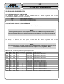
3.5.1 DRIVE ASSIGNMENT ORDER
This field lets you configure the drive assignment. Take care that the first floppy drive is assigned to 'Drive A'
and the first hard disk drive to 'Drive C'.
The following table shows the possible settings for drives A: through K: . Please note that only drive A: and B:
are selectable to be floppy drives.
In order to avoid unnecessary searching for devices during boot up, only drives that are actually connected to
the system should be selected here.
Drive Assignment Order
None
Floppy 0
Floppy 1
USB Floppy
ATA 0/Pri Master
ATA 1/Pri Slave
ATA 2/Sec Master
ATA 3/Sec Slave
USB Hard Drive
No assignment
First floppy drive
Second floppy drive
USB floppy drive
ATA 0 (Primary Master)
ATA 1 (Primary Slave)
ATA 2 (Secondary Master)
ATA 3 (Secondary Slave)
USB hard drive
3.5.2 FLOPPY DRIVE TYPES
Two floppy drives can be used (Floppy 0, Floppy 1), and this option selects the type of each drive.
Floppy Drive Types
Not installed
720 KB, 3.5”
1.44 MB, 3.5”
2.88 MB, 3.5”
360 KB, 5.25”
1.2 MB, 5.25”
2008 by MPL AG
No assignment
720 Kbyte, 3.5 inch floppy drive
1.44 Mbyte, 3.5 inch floppy drive
2.88 Mbyte, 3.5 inch floppy drive
360 Kbyte, 5.25 inch floppy drive
1.2 Mbyte, 5.25 inch floppy drive
20
MEH-10106-181 Rev. D
PIP8
H ig h -Te c h • M a d e in Sw itze rla n d
SYSTEM BIOS USER MANUAL
3.5.3 BOOT ORDER
This table determines the boot order of the system drives. Set the drive letters according to the assignments
made in the drive assignment order table, e.g. 'Drive A:' is equal to 'Drive A:' in the drive assignment order table.
To boot from a bootable CD-ROM media, choose 'CDROM', not the drive letter of the CD-ROM drive. Also make
sure that 'ATA DRIVE ASSIGNMENT' is set to 'ATA CDROM' if the drive is connected via ATA.
If the CD-ROM drive is connected via USB, choosing 'CDROM' is sufficient. For more information about booting
from USB CD-ROM drives, please refer to section 5.
Boot Order
Boot 1st
Boot 2nd
Boot 3rd
Boot 4th
Boot 5th
Boot 6th
First boot device (defaults to 'A:')
Second boot device (defaults to 'CDROM')
Third boot device (defaults to 'C:')
Fourth boot device (defaults to 'None')
Fifth boot device (defaults to 'None')
Sixth boot device (defaults to 'None')
3.5.4 ATA DRIVE ASSIGNMENT
This selects the installed drive type for each of the four possible ATA connections. Please refer to section for
more information about ATA Mass Storage Configuration.
ATA Drv Assignment
Not installed
User Type
Autoconfig, Physical
Autoconfig, LBA
Autoconfig, CHS
ATA CDROM
2008 by MPL AG
No drive installed
The 'USER TYPE' allows to select the maximum cylinders, heads and sectors per track
associated with the connected IDE drive.
The 'PHYSICAL' type instructs the BIOS to query the drive’s geometry from the controller on
each POST. This setting is limited to drives of 512 MB or less.
The 'LBA' type instructs the BIOS to query the drive’s geometry from the controller on each
POST but then translate the geometry according to the LBA standard. Use this setting for
all new drives. This setting may also be used with a CD-ROM drive if booting from CDROM is not needed.
The 'CHS' type instructs the BIOS to query the drive’s geometry from the controller on each
POST but then translate the geometry according to the Phoenix CHS convention.
The 'ATA CDROM' type indicates the drive is a CD-ROM drive, not a hard disk. It forces the
BIOS to search for a bootable CD-ROM media during POST. To save POST time if booting
from CD-ROM is not needed, use 'AUTOCONFIG, LBA' instead.
21
MEH-10106-181 Rev. D
PIP8
H ig h -Te c h • M a d e in Sw itze rla n d
SYSTEM BIOS USER MANUAL
3.5.5 GENERAL SETTINGS
General Settings
Typematic Delay
Typematic Rate
Seek at Boot
Show “Hit DEL”
Config Box
F1 Error Wait
Parity Checking
Memory Test Tick
Debug Breakpoint
Debugger Hex Case
Memory Test
2008 by MPL AG
Delay from pressing and holding a key on the keyboard until the start of character
repeating
Character repetition rate (characters per second; cps)
None
Default
Floppy
Seek for floppy
IDE
(obsolete)
Both
(obsolete)
Enabled
Show at startup the string ”Hit Del to enter the system BIOS” (default)
Disabled
Do not show the string ”Hit Del to enter the system BIOS”
Enabled
Show the configuration box at startup (default)
Disabled
Don’t show the configuration box
Enabled
Wait for F1 key press if an error is encountered at POST (default)
Disabled
Do not wait for F1 key press
(Unused)
This option is not used
Enabled
Click speaker during memory test (default)
Disabled
Don’t click speaker during memory test
(Unused)
Not used
Upper
Not used
Lower
Specifies what type of memory test to perform at POST. Can be selected independently
for low (below 1 Mbyte) and high (above 1 Mbyte) memory.
Fast
Performs a fast memory test (reduces POST time)
Std
Performs a standard memory test (default)
Full
Performs an exhaustive memory test (increases POST time)
22
MEH-10106-181 Rev. D
PIP8
H ig h -Te c h • M a d e in Sw itze rla n d
SYSTEM BIOS USER MANUAL
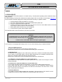
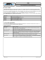
3.6 FEATURES CONFIGURATION
╔══════════════════════════════════════════════════════════════════════════════╗
║
System BIOS Setup - Features Configuration
║
║
(C) 2005 General Software, Inc. All rights reserved
║
╠═══════════════════════════════════════╤══════════════════════════════════════╣
║ ACPI 1.0
:>Enabled
│ System Management Mode
: Enabled
║
║ Graphical POST
: Disabled
│ Primary ATA Mode
: PIO/xDMA ║
║ Secondary ATA Mode
: PIO/xDMA
│ Console Redirection
: Disabled ║
║ UsbHid
: Disabled
│ UsbMassStorage
: Enabled
║
║
│
║
║
│
║
║
│
║
║
│
║
║
│
║
║
│
║
║
│
║
║
│
║
║
│
║
║
│
║
║
│
║
║
│
║
║
│
║
╠═══════════════════════════════════════╧══════════════════════════════════════╣
║
↑/↓/←/→/<CR>/<Tab> to select or <PgUp>/<PgDn>/+/- to modify
║
║
<Esc> to return to main menu
║
╚══════════════════════════════════════════════════════════════════════════════╝
Figure 9: Features Configuration Screen
3.6.1 ACPI 1.0
This option enables or disables support for ACPI V1.0. Enabling this option introduces power saving features
such as Hibernate Mode and Soft Off functionality, if the operating system supports ACPI.
This feature must be enabled if MPL UPS-1 is installed in the system.
Note: This setting should not be changed once the operating system is installed. Unexpected system behavior
could be the result.
ACPI 1.0
Disabled
Enabled
default
Disable ACPI 1.0
Enable ACPI 1.0
3.6.2 SYSTEM MANAGEMENT MODE
This option enables or disables System Management Mode (SMM). SMM is a CPU mode transparent to the
foreground OS.
There are several tasks that are running in SMM. This includes the following BIOS features which are only
available if SMM is enabled:
- USB Mass Storage Support
- USB Legacy Keyboard/Mouse Support
- Some VGA functions (DVI transmitter, LVDS)
Therefore, it is strongly recommended to leave this setting at its default (Enabled).
Note: Due to its nature, the SMM may cause problems if the application requires hard real time capabilities.
The setup options 'UsbHid' (refer to section 3.6.7) and 'UsbMassStorage' (refer to section 3.6.8) are
provided to individually disable SMM features in case of problems.
System Management Mode
Disabled
Disable System Management Mode
default
Enabled
Enable System Management Mode
2008 by MPL AG
23
MEH-10106-181 Rev. D
PIP8
H ig h -Te c h • M a d e in Sw itze rla n d
SYSTEM BIOS USER MANUAL
3.6.3 GRAPHICAL POST
This options lets the system boot with a graphical splash screen instead of the standard, text-based POST
(Power On Self Test) progress indicator.
Graphical POST
default
Disabled
Enabled
Show text information at POST
Show splash screen at POST
3.6.4 PRIMARY ATA MODE
This option controls the transfer mode of the primary ATA channel.
If set to 'PIO/xDMA', the ATA devices connected to the primary ATA channel are configured for their fastest
transfer mode possible, including Programmed IO (PIO), Multi-word DMA (MWDMA) and Ultra DMA (UDMA)
modes, depending on the device's capabilities.
If set to 'PIO Only', the ATA devices run in PIO mode only. This should only be selected if a device does not
work properly with 'PIO/xDMA'.
Primary ATA Mode
default
PIO/xDMA
PIO Only
Use fastest transfer mode possible for Primary ATA channel
Use only PIO mode for Primary ATA channel
3.6.5 SECONDARY ATA MODE
This option controls the transfer mode of the secondary ATA channel.
If set to 'PIO/xDMA', the ATA devices connected to the secondary ATA channel are configured for their fastest
transfer mode possible, including Programmed IO (PIO), Multi-word DMA (MWDMA) and Ultra DMA (UDMA)
modes, depending on the device's capabilities.
If set to 'PIO Only', the ATA devices run in PIO mode only. This should only be selected if a device does not
work properly with 'PIO/xDMA'.
Secondary ATA Mode
default
PIO/xDMA
PIO Only
Use fastest transfer mode possible for Secondary ATA channel
Use only PIO mode for Secondary ATA channel
3.6.6 CONSOLE REDIRECTION
This option controls console redirection. Standard behavior is local display / keyboard.
When set to 'Enabled', console output is routed to Serial Port 1 @ 9600bps, 8N1. There will be no boot
messages on the standard display.
Console Redirection
default
Disabled
Enabled
2008 by MPL AG
Console not redirected
Console redirected to Serial Port 1
24
MEH-10106-181 Rev. D
PIP8
H ig h -Te c h • M a d e in Sw itze rla n d
SYSTEM BIOS USER MANUAL
3.6.7 USB HID
This option enables USB HID (Human Interface Device) support for legacy environments, such as DOS.
Supported devices are keyboards and mice.
This feature requires System Management Mode enabled. If System Management Mode is disabled, UsbHid
will be disabled as well. Please refer to section 3.6.2 for more information about SMM.
Note:
If UsbHid is enabled, IRQ12 will be no longer available for PC/104 devices, even if no PS/2 mouse is
connected. Please refer to section 2.1 for more information about Interrupt usage.
UsbHid
default
Disabled
Enabled
Legacy Human Interface Device support disabled
Legacy Human Interface Device support enabled
3.6.8 USB MASS STORAGE
This option controls USB Mass Storage support for legacy environments and for the purpose of booting from
USB devices. Please refer to section 5 for more information about USB Boot.
This feature requires System Management Mode enabled. If System Management Mode is disabled,
UsbMassStorage will be disabled as well. Please refer to section 3.6.2 for more information about SMM.
Note:
This feature needs to be enabled if the system is configured to boot from USB devices.
UsbMassStorage
Disabled
default
Enabled
2008 by MPL AG
USB Mass Storage Device support disabled
USB Mass Storage Device support enabled
25
MEH-10106-181 Rev. D
PIP8
H ig h -Te c h • M a d e in Sw itze rla n d
SYSTEM BIOS USER MANUAL
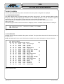
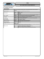
3.7 ONBOARD DEVICES CONFIGURATION
The Onboard Devices Configuration setup contains options that may not be available on specific versions of the
PIP8. If so, the particular option is grayed out and cannot be configured.
╔══════════════════════════════════════════════════════════════════════════════╗
║
System BIOS Setup – Onboard Devices Configuration
║
║
(C) 2005 General Software, Inc. All rights reserved
║
╠══════════════════════════════════════════════════════════════════════════════╣
║┌─────────────────────────────────────┐┌─────────────────────────────────────┐║
║│ Serial 1
:>Enabled
││ Serial 2
: Enabled
│║
║│ Serial 1 IO Base : 3F8h
││ Serial 2 IO Base : 2F8h
│║
║│ Serial 1 IRQ
: 4
││ Serial 2 IRQ
: 3
│║
║└─────────────────────────────────────┘└─────────────────────────────────────┘║
║┌─────────────────────────────────────┐┌─────────────────────────────────────┐║
║│ Serial 3 Mode
: RS232
││ Serial 4 Mode
: RS232
│║
║│ Serial 3 IO Base : 3E8h
││ Serial 4 IO Base : 2E8h
│║
║│ Serial 3 IRQ
: 4
││ Serial 4 IRQ
: 3
│║
║└─────────────────────────────────────┘└─────────────────────────────────────┘║
║┌─────────────────────────────────────┐┌─────────────────────────────────────┐║
║│ Parallel Port
: SPP
││ Floppy Controller : Enabled
│║
║│ Parallel Port IO Base : 378h
│└─────────────────────────────────────┘║
║│ Parallel Port IRQ
: IRQ7
│┌─────────────────────────────────────┐║
║│ PP Floppy Power
:
││ PS/2 Mouse : Auto
│║
║└─────────────────────────────────────┘└─────────────────────────────────────┘║
║
║
╠══════════════════════════════════════════════════════════════════════════════╣
║
↑/↓/←/→/<CR>/<Tab> to select or <PgUp>/<PgDn>/+/- to modify
║
║
<Esc> to return to main menu
║
╚══════════════════════════════════════════════════════════════════════════════╝
Figure 10: Onboard Devices Configuration Screen
3.7.1 SERIAL PORT 1
Serial Port 1
default
Serial Port 1 IO Base
default
Serial Port 1 IRQ
default
Enables / Disables Serial Port 1
Disabled
Serial Port 1 is disabled. The Serial Port 1 options described below become
hidden.
RS232
Serial Port 1 is enabled (RS232 mode)
Selects Serial Port 1 I/O base address
03F8h
Use I/O base address 03F8h
02F8h
Use I/O base address 02F8h
03E8h
Use I/O base address 03E8h
02E8h
Use I/O base address 02E8h
0220h
Use I/O base address 0220h
0228h
Use I/O base address 0228h
0238h
Use I/O base address 0238h
0338h
Use I/O base address 0338h
Selects Serial Port 1 IRQ
3
Use IRQ 3
4
Use IRQ 4 (default: Shared1 with Serial Port 3)
5
Use IRQ 5
7
Use IRQ 7
11
Use IRQ 11
1 Some operating systems are not capable of sharing interrupts between two serial ports. In such cases, select a unique interrupt for each
serial port, e.g. COM1 = IRQ4, COM3 = IRQ11.
2008 by MPL AG
26
MEH-10106-181 Rev. D
PIP8
H ig h -Te c h • M a d e in Sw itze rla n d
SYSTEM BIOS USER MANUAL
3.7.2 SERIAL PORT 2
Serial Port 2
default
Serial Port 2 IO Base
default
Serial Port 2 IRQ
default
Note:
Selects Serial Port 2 mode
Disabled
Serial Port 2 is disabled. The Serial Port 2 options described below
become hidden.
RS232
RS232 mode (requires SERIF-1 module)
RS485 Half Duplex
RS485 half–duplex mode (requires SERIF-2 module)
RS485 Full Duplex
RS485 / RS422 full-duplex mode (requires SERIF-2 module)
Selects Serial Port 2 I/O base address
03F8h
Use I/O base address 03F8h
02F8h
Use I/O base address 02F8h
03E8h
Use I/O base address 03E8h
02E8h
Use I/O base address 02E8h
Selects Serial Port 2 IRQ
3
Use IRQ 3 (default: Shared2 with Serial Port 4)
4
Use IRQ 4
5
Use IRQ 5
7
Use IRQ 7
11
Use IRQ 11
Serial Port 2 can only be used if a SERIF module is present.
3.7.3 SERIAL PORT 3
Serial Port 3
default
Serial Port 3 IO Base
default
Serial Port 3 IRQ
default
Enables / Disables Serial Port 3
Disabled
Serial Port 3 is disabled. The Serial Port 3 options described below become
hidden.
RS232
Serial Port 3 is enabled (RS232 mode)
Selects Serial Port 3 I/O base address
03F8h
Use I/O base address 03F8h
02F8h
Use I/O base address 02F8h
03E8h
Use I/O base address 03E8h
02E8h
Use I/O base address 02E8h
0220h
Use I/O base address 0220h
0228h
Use I/O base address 0228h
0238h
Use I/O base address 0238h
0338h
Use I/O base address 0338h
Selects Serial Port 3 IRQ
3
Use IRQ 3
4
Use IRQ 4 (default: Shared3 with Serial Port 1)
5
Use IRQ 5
7
Use IRQ 7
11
Use IRQ 11
2
Some operating systems are not capable of sharing interrupts between two serial ports. In such cases, select a unique interrupt for each
serial port, e.g. COM2 = IRQ3, COM4 = IRQ5.
3 Some operating systems are not capable of sharing interrupts between two serial ports. In such cases, select a unique interrupt for each
serial port, e.g. COM1 = IRQ4, COM3 = IRQ11.
2008 by MPL AG
27
MEH-10106-181 Rev. D
PIP8
H ig h -Te c h • M a d e in Sw itze rla n d
SYSTEM BIOS USER MANUAL
3.7.4 SERIAL PORT 4
Serial Port 4
default
Serial Port 4 IO Base
default
Serial Port 4 IRQ
default
Note:
Selects Serial Port 4 mode
Disabled
Serial Port 4 is disabled. The Serial Port 4 options described below
become hidden.
RS232
RS232 mode (requires SERIF-1 module)
RS485 Half Duplex
RS485 half–duplex mode (requires SERIF-2 module)
RS485 Full Duplex
RS485 / RS422 full-duplex mode (requires SERIF-2 module)
Selects Serial Port 4 I/O base address
03F8h
Use I/O base address 03F8h
02F8h
Use I/O base address 02F8h
03E8h
Use I/O base address 03E8h
02E8h
Use I/O base address 02E8h
Selects Serial Port 4 IRQ
3
Use IRQ 3 (default: Shared4 with Serial Port 2)
4
Use IRQ 4
5
Use IRQ 5
7
Use IRQ 7
11
Use IRQ 11
Serial Port 4 can only be used if a SERIF module is inserted.
3.7.5 PARALLEL PORT
Parallel Port
default
Parallel Port IO Base
default
Parallel Port IRQ
default
PP Floppy Power
default
Selects Parallel Port mode
Disabled
Parallel Port is disabled. The Parallel Port options described below become
hidden.
SPP
Standard bidirectional mode
Printer
Printer mode
SPP / EPP 1.7
SPP and EPP 1.7 mode
SPP / EPP 1.9
SPP and EPP 1.9 mode
ECP
ECP mode
ECP / EPP 1.7
ECP and EPP 1.7 mode
ECP / EPP 1.9
ECP and EPP 1.9 mode
PP Floppy
The parallel port connector uses 'Floppy Disk Mode' pin configuration (refer
to PIP8 User Manual). In this mode, the Floppy signals are redirected to the
parallel port connector so that external floppy disk drives can be connected.
The original parallel port functionality is not available any more. The internal
floppy connector is also non-functional.
Selects Parallel Port I/O base address
0378h
Use I/O base address 0378h
0278h
Use I/O base address 0278h
Selects Parallel Port IRQ
3
Use IRQ 3
4
Use IRQ 4
5
Use IRQ 5
7
Use IRQ 7
11
Use IRQ 11
Enables / disables power for a parallel port floppy
Disabled
Enabled
Provide +5V on pin 25. Can only be enabled if Parallel Port mode is 'PP Floppy'.
4
Some operating systems are not capable of sharing interrupts between two serial ports. In such cases, select a unique interrupt for each
serial port, e.g. COM2 = IRQ3, COM4 = IRQ5.
2008 by MPL AG
28
MEH-10106-181 Rev. D
PIP8
H ig h -Te c h • M a d e in Sw itze rla n d
SYSTEM BIOS USER MANUAL
3.7.6 FLOPPY CONTROLLER
This option controls the Floppy Controller.
Note: If a parallel port floppy is used, this option needs to be enabled also.
Floppy Controller
default
Enables / disables the Floppy Controller
Disabled
Floppy Controller is disabled
Enabled
Floppy Controller is enabled
3.7.7 PS/2 MOUSE
This option controls the PS/2 Mouse port.
It can be used to free IRQ12 for usage by a PC/104 card if there is no PS/2 mouse in the system. Please refer
to section 2.1 for more information.
Note: This option can be helpful if the mouse is not detected properly with the 'Auto' setting, e.g. when a
KVM (Keyboard, Video, Mouse) switch is used. In this case, it should be set to 'Enabled' to override
auto detection.
PS/2 Mouse
default
2008 by MPL AG
Controls PS/2 Mouse port
Disabled
PS/2 Mouse port is disabled. Pointing devices connected to this port do not
work. IRQ12 is free.
Auto
PS/2 Mouse port is automatically enabled if a pointing device is detected (IRQ12
is used). The mouse port is disabled if no pointing device is detected (IRQ12 is
free).
Enabled
PS/2 Mouse port is always enabled. IRQ12 is used.
29
MEH-10106-181 Rev. D
PIP8
H ig h -Te c h • M a d e in Sw itze rla n d
SYSTEM BIOS USER MANUAL
3.8 SPECIAL CONFIGURATION
The Special Configuration setup contains options that may not be available on specific versions of the PIP8. If
so, the particular option is grayed out and cannot be configured.
╔══════════════════════════════════════════════════════════════════════════════╗
║
System BIOS Setup – Special Configuration
║
║
(C) 2005 General Software, Inc. All rights reserved
║
╠══════════════════════════════════════════════════════════════════════════════╣
║┌─────────────────────────────────────┐┌─────────────────────────────────────┐║
║│ Panel Fitting : >All Stretched
││ Mass Storage Mode : P-ATA Only
│║
║│ Panel Backlight : BIOS Control
││ Combined Mode
:
│║
║│ Brightness Level : 50%
│└─────────────────────────────────────┘║
║└─────────────────────────────────────┘┌─────────────────────────────────────┐║
║┌─────────────────────────────────────┐│ PC104 MEM Base Addr : Disabled
│║
║│ PXE Boot ROM : Enabled
││ PC104 MEM Length
:
│║
║└─────────────────────────────────────┘└─────────────────────────────────────┘║
║┌─────────────────────────────────────┐
║
║│ CPU Frequency : 1000MHz
│
║
║└─────────────────────────────────────┘
║
║┌─────────────────────────────────────┐
║
║│ AC97 Audio : Auto
│
║
║└─────────────────────────────────────┘
║
║┌─────────────────────────────────────┐
║
║│ Min UPS Charge to Boot : Disabled
│
║
║└─────────────────────────────────────┘
║
╠══════════════════════════════════════════════════════════════════════════════╣
║
↑/↓/←/→/<CR>/<Tab> to select or <PgUp>/<PgDn>/+/- to modify
║
║
<Esc> to return to main menu
║
╚══════════════════════════════════════════════════════════════════════════════╝
Figure 11: Special Configuration Screen
3.8.1 LVDS PANEL SETTINGS
These options control panels connected to the PIP8 via LVDS interface.
Please refer to section 2.5.2 for detailed information about the Flat Panel (LVDS) interface of the PIP8.
Note:
These options are only active if a LVDS panel is connected and properly configured via DIP switches.
If the monitor is connected to the DVI-I port of the PIP8, these options are inactive and do not affect
the display output.
3.8.1.1 PANEL FITTING
This option controls the fitting of the panel contents.
If the native resolution of a panel does not correspond to the software resolution, the contents is either stretched
to fit the native screen resolution or centered, which results in a black frame around the actual screen content.
Panel Fitting
default
Controls panel fitting behavior
All Stretched
Always fit the screen size (default)
Gfx Stretched
Graphics Modes are stretched to fit the screen
Text Stretched
Text modes are stretched to fit the screen
All Centered
Both Graphics and Text modes are centered
3.8.1.2 PANEL BACKLIGHT
This option defines how the backlight brightness level is controlled. If set to 'BIOS Control', the brightness can
be adjusted with the option 'Brightness Level'.
Panel Backlight
default
2008 by MPL AG
Defines backlight brightness control
HW/App Control
Brightness controlled by hardware or application
BIOS Control
Brightness controlled by BIOS setup
30
MEH-10106-181 Rev. D
PIP8
H ig h -Te c h • M a d e in Sw itze rla n d
SYSTEM BIOS USER MANUAL
3.8.1.3 BRIGHTNESS LEVEL
If 'Panel Backlight' is set to 'BIOS Control', the backlight brightness can be adjusted in 5% increments.
Brightness Level
default
Selects brightness level of the backlight, if 'BIOS Control' is selected
Minimal
Minimal brightness level
5%
5% brightness level
10%
10% brightness level
...
...
...
[5% increments]
...
...
95%
95% brightness level
100%
100% brightness level
3.8.2 PXE BOOT ROM
This option enables / disables the integrated PXE Boot ROM which allows the system to boot from network
(please refer to section 6 for detailed information).
Disabling this ROM frees memory in the D segment which can be used for other option ROMs or devices that
use memory in this range. Please refer to section 2.2 for more details about the memory map.
PXE Boot ROM
default
Enables / disables Network Boot
Disabled
PXE Boot ROM is disabled
Enabled
PXE Boot ROM is enabled
3.8.3 MASS STORAGE
The PIP8 supports only Parallel ATA (P-ATA) devices. Therefore, this option is not adjustable.
Mass Storage Mode
default
Combined Mode
default
Selects the Mass Storage Mode
P-ATA Only
Use Parallel ATA only
Selects the primary channel for Combined Mode
N/A
3.8.4 PC104 MEM BASE
This option reserves memory space for legacy ISA (PC/104) cards.
Note:
C and D segments are also the space where option ROMs such as the integrated PXE ROM are
loaded. Routing this memory space to PC/104 can result in loss of Option ROM functionality. Please
refer to section 2.2 for further details about the default memory layout of the PIP8.
PC104 MEM Base Addr Defines the base address of the memory range to be routed to PC/104
default
Disabled
Memory window disabled. The MEM length option described below becomes
hidden.
D000
Memory window starting at D0000h
D400
Memory window starting at D4000h
D800
Memory window starting at D8000h
DC00
Memory window starting at DC000h
PC104 MEM Length
Defines the size of the memory range
default
8k
Memory window size 8 k (2000h)
16k
Memory window size 16 k (4000h)
32k
Memory window size 32 k (8000h)
64k
Memory window size 64 k (10000h)
2008 by MPL AG
31
MEH-10106-181 Rev. D
PIP8
H ig h -Te c h • M a d e in Sw itze rla n d
SYSTEM BIOS USER MANUAL
3.8.5 CPU FREQUENCY
The Celeron-M processor of the PIP8 supports a fixed CPU speed only. Therefore, this option is not adjustable.
CPU Frequency
default
Controls the CPU speed
1000MHz
CPU runs fixed @ 1000MHz without SpeedStep
3.8.6 AC97 AUDIO
This option controls the onboard AC'97 audio device.
Note: This option is only useful if the MPL SoundPAN-1 option is installed.
AC97 Audio
default
Controls AC'97 audio device
Auto
AC'97 audio device is enabled automatically if the MPL SoundPAN-1 option is
installed. If SoundPAN-1 is not present, the AC'97 device is disabled.
Disabled
Manually disable AC'97 audio device.
3.8.7 MIN UPS CHARGE TO BOOT
If MPL UPS-1 is present in the system, this option configures the required UPS battery charge level for
operating system boot. If enabled, the start of the installed operating system is delayed until the UPS battery
has reached the configured charge level.
If no UPS-1 was detected, the option is disabled and not adjustable.
Min UPS Charge to Boot Defines the minimal UPS battery level required to boot the system
Disabled
The system does not check for minimum battery charge level. It always boots.
(Not recommended)
default
20%
The system boots the OS after the battery charge level has reached 20%.
40%
The system boots the OS after the battery charge level has reached 40%.
60%
The system boots the OS after the battery charge level has reached 60%.
2008 by MPL AG
32
MEH-10106-181 Rev. D
PIP8
SYSTEM BIOS USER MANUAL
H ig h -Te c h • M a d e in Sw itze rla n d
3.9 SHADOW RAM CONFIGURATION
╔══════════════════════════════════════════════════════════════════════════════╗
║
System BIOS Setup - Shadow/Cache Configuration
║
║
(C) 2005 General Software, Inc. All rights reserved
║
╠═══════════════════════════════════════╤══════════════════════════════════════╣
║ Shadow 16KB ROM at D000 :>Enabled
│ Shadow 16KB ROM at D400 : Enabled
║
║ Shadow 16KB ROM at D800 : Enabled
│ Shadow 16KB ROM at DC00 : Enabled
║
║
│
║
║
│
║
║
│
║
║
│
║
║
│
║
║
│
║
║
│
║
║
│
║
║
│
║
║
│
║
║
│
║
║
│
║
║
│
║
║
│
║
║
│
║
╠═══════════════════════════════════════╧══════════════════════════════════════╣
║
↑/↓/←/→/<CR>/<Tab> to select or <PgUp>/<PgDn>/+/- to modify
║
║
<Esc> to return to main menu
║
╚══════════════════════════════════════════════════════════════════════════════╝
Figure 12: Shadow RAM Configuration Screen
Shadow Configuration controls the shadowability of certain memory ranges.
If a certain memory range is used as ISA (PC/104) memory, shadowing should be disabled.
If Option ROMs need to be installed, it must be assured that a consecutive Shadow area big enough to hold the
Option ROM is enabled.
Please refer to section 2.2 for more details about the memory map.
Shadow Region
Physical Address
Segment Address
16KB ROM at D000
D0000h – D3FFFh
D000 – D3FF
16KB ROM at D400
D4000h – D7FFFh
D400 – D7FF
16KB ROM at D800
D8000h – DBFFFh
D800 – DBFF
16KB ROM at DC00
DC000h – DFFFFh
DC00 – DFFF
2008 by MPL AG
33
Disabled
Enabled
Disabled
Enabled
Disabled
Enabled
Disabled
Enabled
default
default
default
default
MEH-10106-181 Rev. D
PIP8
H ig h -Te c h • M a d e in Sw itze rla n d
SYSTEM BIOS USER MANUAL
3.10 PLUG-N-PLAY CONFIGURATION
╔══════════════════════════════════════════════════════════════════════════════╗
║
System BIOS Setup - Plug-n-Play Configuration
║
║
(C) 2005 General Software, Inc. All rights reserved
║
╠═══════════════════════════════════════╤══════════════════════════════════════╣
║ Enable PnP Support
:>Enabled
│ Enable PnP O/S
: Enabled
║
║
│
║
║ Assign IRQ0 to PnP
: Enabled
│ Assign IRQ8 to PnP
: Enabled
║
║ Assign IRQ1 to PnP
: Enabled
│ Assign IRQ9 to PnP
: Enabled
║
║ Assign IRQ2 to PnP
: Enabled
│ Assign IRQ10 to PnP
: Enabled
║
║ Assign IRQ3 to PnP
: Enabled
│ Assign IRQ11 to PnP
: Enabled
║
║ Assign IRQ4 to PnP
: Enabled
│ Assign IRQ12 to PnP
: Enabled
║
║ Assign IRQ5 to PnP
: Enabled
│ Assign IRQ13 to PnP
: Enabled
║
║ Assign IRQ6 to PnP
: Enabled
│ Assign IRQ14 to PnP
: Enabled
║
║ Assign IRQ7 to PnP
: Enabled
│ Assign IRQ15 to PnP
: Enabled
║
║
│
║
║ Assign DMA0 to PnP
: Enabled
│ Assign DMA4 to PnP
: Enabled
║
║ Assign DMA1 to PnP
: Enabled
│ Assign DMA5 to PnP
: Enabled
║
║ Assign DMA2 to PnP
: Enabled
│ Assign DMA6 to PnP
: Enabled
║
║ Assign DMA3 to PnP
: Enabled
│ Assign DMA7 to PnP
: Enabled
║
║
│
║
║
│
║
╠═══════════════════════════════════════╧══════════════════════════════════════╣
║
↑/↓/←/→/<CR>/<Tab> to select or <PgUp>/<PgDn>/+/- to modify
║
║
<Esc> to return to main menu
║
╚══════════════════════════════════════════════════════════════════════════════╝
Figure 13: Plug-N-Play Configuration Screen
3.10.1 GENERAL PNP CONFIGURATION
Enable PnP Support
default
Enable PnP O/S
default
2008 by MPL AG
Enables / Disables Plug-N-Play support
Disabled
Plug-N-Play support is disabled
Enabled
Plug-N-Play support is enabled
Must be set according to the installed operating system (OS)
Disabled
Disable it if OS is not capable of PnP
Enabled
Enable it if OS is capable of PnP
34
MEH-10106-181 Rev. D
PIP8
H ig h -Te c h • M a d e in Sw itze rla n d
SYSTEM BIOS USER MANUAL
3.10.2 PNP IRQ CONFIGURATION
Assign IRQx to PnP
IRQ0
IRQ1
IRQ2
IRQ3
IRQ4
IRQ5
IRQ6
IRQ7
IRQ8
IRQ9
IRQ10
IRQ11
IRQ12
IRQ13
IRQ14
IRQ15
Defines which IRQs are available for PnP devices
Disabled
IRQ0 not available for PnP devices
Enabled
IRQ0 available for PnP devices (default)
Disabled
IRQ1 not available for PnP devices
Enabled
IRQ1 available for PnP devices (default)
Disabled
IRQ2 not available for PnP devices
Enabled
IRQ2 available for PnP devices (default)
Disabled
IRQ3 not available for PnP devices
Enabled
IRQ3 available for PnP devices (default)
Disabled
IRQ4 not available for PnP devices
Enabled
IRQ4 available for PnP devices (default)
Disabled
IRQ5 not available for PnP devices
Enabled
IRQ5 available for PnP devices (default)
Disabled
IRQ6 not available for PnP devices
Enabled
IRQ6 available for PnP devices (default)
Disabled
IRQ7 not available for PnP devices
Enabled
IRQ7 available for PnP devices (default)
Disabled
IRQ8 not available for PnP devices
Enabled
IRQ8 available for PnP devices (default)
Disabled
IRQ9 not available for PnP devices
Enabled
IRQ9 available for PnP devices (default)
Disabled
IRQ10 not available for PnP devices
Enabled
IRQ10 available for PnP devices (default)
Disabled
IRQ11 not available for PnP devices
Enabled
IRQ11 available for PnP devices (default)
Disabled
IRQ12 not available for PnP devices
Enabled
IRQ12 available for PnP devices (default)
Disabled
IRQ13 not available for PnP devices
Enabled
IRQ13 available for PnP devices (default)
Disabled
IRQ14 not available for PnP devices
Enabled
IRQ14 available for PnP devices (default)
Disabled
IRQ15 not available for PnP devices
Enabled
IRQ15 available for PnP devices (default)
3.10.3 PNP DMA CONFIGURATION
Assign DMAx to PnP
DMA0
DMA1
DMA2
DMA3
DMA4
DMA5
DMA6
DMA7
2008 by MPL AG
Defines which DMAs are available for PnP devices
Disabled
DMA0 not available for PnP devices
Enabled
DMA0 available for PnP devices (default)
Disabled
DMA1 not available for PnP devices
Enabled
DMA1 available for PnP devices (default)
Disabled
DMA2 not available for PnP devices
Enabled
DMA2 available for PnP devices (default)
Disabled
DMA3 not available for PnP devices
Enabled
DMA3 available for PnP devices (default)
Disabled
DMA4 not available for PnP devices
Enabled
DMA4 available for PnP devices (default)
Disabled
DMA5 not available for PnP devices
Enabled
DMA5 available for PnP devices (default)
Disabled
DMA6 not available for PnP devices
Enabled
DMA6 available for PnP devices (default)
Disabled
DMA7 not available for PnP devices
Enabled
DMA7 available for PnP devices (default)
35
MEH-10106-181 Rev. D
PIP8
H ig h -Te c h • M a d e in Sw itze rla n d
SYSTEM BIOS USER MANUAL
4 NONVOLATILE BIOS SETUP
4.1 OVERVIEW
The PIP8 BIOS features the option to permanently save the BIOS settings into the Flash memory. This memory
is nonvolatile, therefore the BIOS settings do not get lost if the battery is dead or removed. It is no longer
necessary to manually reconfigure the BIOS in these cases.
If the BIOS detects that the settings are corrupt, it checks whether the Flash contains a valid image of the BIOS
settings and if so, it loads the settings from the Flash. If there is no valid image in the Flash, it loads the factory
default settings.
If the BIOS is updated, the Flash memory area holding the BIOS settings is erased as well. This prevents
configuration errors if the new BIOS introduces additional BIOS settings or if it redefines existing settings.
To take full advantage of the nonvolatile BIOS setup feature, it is recommended to save the BIOS settings to the
Flash once the BIOS is properly configured for your application.
NOTE
The date and time values will not be saved in the Flash.
4.2 USAGE
The feature is controlled by two options in the Main BIOS Setup Menu.
•
•
Save CMOS to nonvolatile Flash
Load CMOS from nonvolatile Flash
╔══════════════════════════════════════════════════════════════════════════════╗
║
System Bios Setup - Utility v5.3
║
║
(C) 2005 General Software, Inc. All rights reserved
║
╠═════════════════════════════╤════════════════════════════════════════════════╣
║
│
║
║
│
║
║
│
>Basic CMOS Configuration
║
║ System Information:
│
Features Configuration
║
║
│
Onboard Devices Configuration
║
║ Model: PIP8 (0xA1, 0x81)
│
Special Configuration
║
║ PLD:
Revision 0x00
│
PnP Configuration
║
║
│
Shadow Configuration
║
║ BIOS Version: V1.40
│
Save CMOS to nonvolatile Flash
║
║ Build Date:
01/17/08
│
Load CMOS from nonvolatile Flash
║
║ BIOS No:
MEV-10100-081 │
Reset CMO to last known values
║
║
│
Reset CMOS to factory defaults
║
║ LAN:
Dev 0x1209 R 0x10 │
Write to CMOS and Exit
║
║ MAC Addr: 00:60:C2:10:XX:XX │
Exit without changing CMOS
║
║
│
║
║
│
║
║
│
║
╠═════════════════════════════╧════════════════════════════════════════════════╣
║
↑/↓/<Tab> to select. <Esc> to continue (no save)
║
║
www.gensw.com
║
╚══════════════════════════════════════════════════════════════════════════════╝
Figure 14: Main BIOS Setup Menu
2008 by MPL AG
36
MEH-10106-181 Rev. D
PIP8
H ig h -Te c h • M a d e in Sw itze rla n d
SYSTEM BIOS USER MANUAL
4.2.1 SAVE CMOS TO NONVOLATILE FLASH
This writes the current BIOS settings to the Flash.
A dialog box pops up and asks for confirmation.
║
║
║
║
║
Model: PIP8 (0xA1, 0x81)
│
Special Configuration
PLD:
Revision 0╔═══════════════════════════════════════════╗
║ Save CMOS settings to Flash? (Y/N):
║n
BIOS Version: V1.╚═══════════════════════════════════════════╝ Flash
Build Date:
01/17/08
│
Load CMOS from nonvolatile Flash
║
║
║
║
║
Figure 15: Save CMOS Dialog Box
Press <Y> to save the BIOS settings in the Flash or <N> to cancel and return to the main BIOS setup menu.
4.2.2 LOAD CMOS FROM NONVOLATILE FLASH
Use this to manually read the BIOS settings from the Flash.
A dialog box pops up and asks for confirmation.
║
║
║
║
║
Model: PIP8 (0xA1, 0x81)
│
Special Configuration
PLD:
Revision 0╔═══════════════════════════════════════════╗
║ Load CMOS settings from Flash? (Y/N):
║n
BIOS Version: V1.╚═══════════════════════════════════════════╝ Flash
Build Date:
01/17/08
│
Load CMOS from nonvolatile Flash
║
║
║
║
║
Figure 16: Load CMOS Dialog Box
Press <Y> to load the BIOS settings from the Flash or <N> to cancel and return to the main BIOS setup menu.
4.2.2.1 CMOS LOAD ERROR
If there is no valid image of the BIOS settings stored in the Flash (e.g. directly after a BIOS update), the
following dialog box pops up, indicating that the BIOS settings have not been loaded from the Flash.
║
║
║
║
║
Model: PIP8 (0xA1, 0x81)
│
Special Configuration
PLD:
Revision 0╔═══════════════════════════════════════════╗
║ No valid data in Flash! Loading aborted. ║n
BIOS Version: V1.╚═══════════════════════════════════════════╝ Flash
Build Date:
01/17/08
│
Load CMOS from nonvolatile Flash
║
║
║
║
║
Figure 17: Load CMOS Error Dialog
In this case, press any key to return to the main BIOS setup menu.
2008 by MPL AG
37
MEH-10106-181 Rev. D
PIP8
H ig h -Te c h • M a d e in Sw itze rla n d
SYSTEM BIOS USER MANUAL
5 USB BOOT
5.1 OVERVIEW
The PIP8 BIOS supports booting from USB mass storage devices, such as:
•
•
•
•
CD / DVD drives
Flash drives ('USB Sticks', 'USB Pen Drives', 'USB Memory Sticks')
Hard disk drives
Floppy disk drives
NOTE
If you experience problems with a certain USB device, please try a different model. There is a
vast variety of USB devices available on the market, and some of them may prove
incompatible with the USB host controller of the PIP8.
5.2 BIOS SETTINGS
The following are the necessary steps to configure the system to boot from USB devices.
•
Make sure that the options 'System Management Mode' and 'UsbMassStorage' are both enabled.
These options are located in the 'Features Configuration' menu.
╔══════════════════════════════════════════════════════════════════════════════╗
║
System BIOS Setup - Features Configuration
║
║
(C) 2005 General Software, Inc. All rights reserved
║
╠═══════════════════════════════════════╤══════════════════════════════════════╣
║ ACPI 1.0
:>Enabled
│ System Management Mode
: Enabled
║
║ Graphical POST
: Disabled
│ Primary ATA UDMA
: Enabled
║
║ Secondary ATA UDMA
: Enabled
│ Console Redirection
: Disabled ║
║ UsbHid
: Disabled
│ UsbMassStorage
: Enabled
║
║
│
║
║
│
║
║
│
║
║
│
║
║
│
║
║
│
║
║
│
║
║
│
║
║
│
║
║
│
║
║
│
║
║
│
║
║
│
║
╠═══════════════════════════════════════╧══════════════════════════════════════╣
║
↑/↓/←/→/<CR>/<Tab> to select or <PgUp>/<PgDn>/+/- to modify
║
║
<Esc> to return to main menu
║
╚══════════════════════════════════════════════════════════════════════════════╝
Figure 18: Features Configuration for USB Boot
2008 by MPL AG
38
MEH-10106-181 Rev. D
PIP8
H ig h -Te c h • M a d e in Sw itze rla n d
•
SYSTEM BIOS USER MANUAL
Configure the USB drive in the 'Basic CMOS Configuration' menu.
╔══════════════════════════════════════════════════════════════════════════════╗
║
System BIOS Setup - Basic CMOS Configuration
║
║
(C) 2005 General Software, Inc. All rights reserved
║
╠═══════════════════════════╤════════════════════╤═════════════════════════════╣
║ DRIVE ASSIGNMENT ORDER:
│ Date:>Apr 15, 2008 │ Typematic Delay : 250 ms
║
║ Drive A: USB Floppy
│ Time: 20 : 21 : 12 │ Typematic Rate
: 30 cps
║
║ Drive B: (None)
│ NumLock: Enabled │ Seek at Boot
: None
║
║ Drive C: USB Hard Drive
├────────────────────┤ Show "Hit Del"
: Enabled ║
║ Drive D: ATA 2/Sec Master │ BOOT ORDER:
│ Config Box
: Enabled ║
║ Drive E: (None)
│ Boot 1st: Drive A: │ F1 Error Wait
: Enabled ║
║ Drive F: (None)
│ Boot 2nd: CDROM
│ Parity Checking : (Unused) ║
║ Drive G: (None)
│ Boot 3rd: Drive C: │ Memory Test Tick : Disabled ║
║ Drive H: (None)
│ Boot 4th: (None)
│ Debug Breakpoints: (Unused) ║
║ Drive I: (None)
│ Boot 5th: (None)
│ Debugger Hex Case: Upper
║
║ Drive J: (None)
│ Boot 6th: (None)
│ Memory Test : StdLo FastHi ║
║ Drive K: (None)
├────────────────────┴─────────────────┬───────────╢
║ (Loader): (Unused)
│ ATA DRV ASSIGNMENT: Sect Hds Cyls │ Memory
║
╟───────────────────────────┤ ATA 0: 3 = AUTOCONFIG, LBA
│ Base:
║
║ FLOPPY DRIVE TYPES:
│ ATA 1: 3 = AUTOCONFIG, LBA
│
632KB
║
║ Floppy 0: 1.44 MB, 3.5"
│ ATA 2: 3 = AUTOCONFIG, LBA
│ Ext:
║
║ Floppy 1: Not installed
│ ATA 3: 3 = AUTOCONFIG, LBA
│
501MB
║
╠═══════════════════════════╧══════════════════════════════════════╧═══════════╣
║
↑/↓/←/→/<CR>/<Tab> to select or <PgUp>/<PgDn>/+/- to modify
║
║
<Esc> to return to main menu
║
╚══════════════════════════════════════════════════════════════════════════════╝
Figure 19: Basic CMOS Configuration for USB Boot
•
To boot from a USB CDROM drive:
•
Select 'CDROM' in the 'Boot Order' menu. 'Drive Assignment Order' does not have to be configured.
In the above example screen, the system is configured to boot from USB CDROM as second boot
source.
•
To boot from a USB Hard Disk drive (e.g. USB Flash Drive, external Hard Disk Drive):
•
Configure one of drives C: thru K: as 'USD Hard Drive' in the 'Drive Assignment Order' menu.
•
Make sure that in the 'Boot Order' menu, the respective drive is selected as well.
In the above example screen, the system is configured to boot from USB Hard Disk drive as third boot
source.
•
To boot from a USB Floppy:
•
Configure one of drives A: thru B: as 'USB Floppy' in the 'Drive Assignment Order' menu.
•
Make sure that in the 'Boot Order' menu, the respective drive is selected as well.
In the above example screen, the system is configured to boot from USB Floppy drive A: first.
2008 by MPL AG
39
MEH-10106-181 Rev. D
PIP8
SYSTEM BIOS USER MANUAL
H ig h -Te c h • M a d e in Sw itze rla n d
6 NETWORK BOOT (PXE)
The PIP8 BIOS supports booting from the onboard Ethernet controller using the PXE protocol.
The following message indicates PXE being initialized:
Initializing Intel(R) Boot Agent FE v4.1.21
PXE 2.1 Build 086 (WfM 2.0)
Press Ctrl+S to enter the Setup Menu...
Figure 20: PXE Boot Message
6.1 PXE CONFIGURATION
The PXE configuration menu is entered by pressing <CTRL>+<S> when indicated by the PXE initialization
message displayed above.
The following table shows the configuration options.
Network Boot Protocol
default
Boot Order
PXE (Preboot eXecution Environment)
Try network first, then local drives
default
Try local drives first, then network
Try network only
Try local drives only
Use PXE as boot protocol
If no boot source is found on the network, the standard
BIOS boot order (refer to section 3.5.3) is executed.
Otherwise, the system boots from network.
If the BIOS boot order (refer to section 3.5.3) does not
contain a bootable device, the network boot is executed.
Otherwise, the system boots from a bootable local drive.
The system boots from network only. The BIOS boot order
(refer to section 3.5.3) is skipped.
The system boots from local drives as configured in the
BIOS boot order (refer to section 3.5.3) only. Network boot
is skipped.
Show Setup Prompt
default
Setup Menu Wait Time
default
Disabled
Enabled
0
2
3
5
Do not show "Press Ctrl+S to enter the Setup Menu..."
Show "Press Ctrl+S to enter the Setup Menu..."
Waits 0 sec for Ctrl+S
Waits 2 sec for Ctrl+S
Waits 3 sec for Ctrl+S
Waits 5 sec for Ctrl+S
6.2 CHANGING THE CONFIGURATION
<ESC>
<SPACE>
<ENTER>
<F4>
Leave Setup Menu and lose changes.
Change value.
Jump to next option.
Save changes and leave Setup menu.
6.3 BOOTING FROM NETWORK
Setting up a server that provides bootable images for network clients is a non-easy task which is beyond the
scope of this manual. The PIP8 merely makes available the feature of booting from a correctly configured boot
server.
Please visit the Intel website at http://support.intel.com/support/network/adapter/pro100/bootagent/index.htm for
further information.
2008 by MPL AG
40
MEH-10106-181 Rev. D
PIP8
H ig h -Te c h • M a d e in Sw itze rla n d
SYSTEM BIOS USER MANUAL
This page is left blank intentionally.
2008 by MPL AG
41
MEH-10106-181 Rev. D
PIP8
H ig h -Te c h • M a d e in Sw itze rla n d
SYSTEM BIOS USER MANUAL
This page is left blank intentionally.
2008 by MPL AG
42
MEH-10106-181 Rev. D
PIP8
H ig h -Te c h • M a d e in Sw itze rla n d
SYSTEM BIOS USER MANUAL
This page is left blank intentionally.
2008 by MPL AG
43
MEH-10106-181 Rev. D
PIP8
H ig h -Te c h • M a d e in Sw itze rla n d
SYSTEM BIOS USER MANUAL
7 COPYRIGHT
Copyright © 2008 by MPL AG Elektronikunternehmen. All rights are reserved. Reproduction of this document in
part or whole, by any means is prohibited, without written permission from MPL AG Elektronikunternehmen.
8 DISCLAIMER
MPL AG has fully tested the PIP8 and reviewed the documentation. However, MPL AG makes no warranty or
representation, either expressed, or implied, with respect to this product, its quality, performance,
merchantability, or fitness for a particular purpose.
In no event will MPL AG be liable for direct, indirect, special, incidental, or consequential damages resulting
from any defect in the product or its documentation, even if advised of the possibility of such damages. In
particular MPL AG shall have no liability for any parts connected to this product.
MPL AG reserves the right to make changes to any product herein to improve reliability, function or design.
9 TRADEMARKS
Brand or product names are trademarks and registered trademarks of their respective holders.
10 SUPPORT
In case of general information questions please feel free to contact us at our homepage (www.mpl.ch) or per
email ([email protected]).
In case of sales information questions please send an email to [email protected].
If you have a technical problem with a PIP8, first please read the User Manual, the Technical Reference Manual
and also this manual carefully. If you can’t solve the problem on your own you can contact us for technical
support per email at [email protected].
Our local Distributor:
2008 by MPL AG
44
MEH-10106-181 Rev. D