1
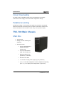
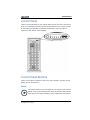
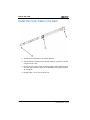
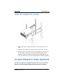
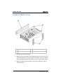
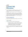
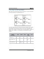
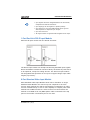
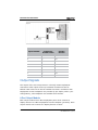
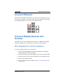
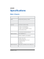
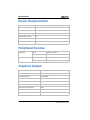
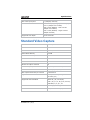
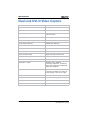
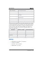
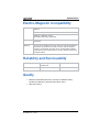
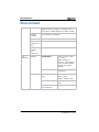
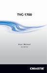
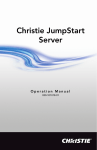
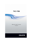
TVC-700 User Manual 020-100906-01 TVC-700 User Manual 020-100906-01 NOTICES COPYRIGHT AND TRADEMARKS © 2013 Christie Digital Systems USA, Inc. - All rights reserved. All brand names and product names are trademarks, registered trademarks or trade names of their respective holders. REGULATORY The product has been tested and found to comply with the limits for a Class A digital device, pursuant to Part 15 of the FCC Rules. These limits are designed to provide reasonable protection against harmful interference when the product is operated in a commercial environment. The product generates, uses, and can radiate radio frequency energy and, if not installed and used in accordance with the instruction manual, may cause harmful interference to radio communications. Operation of the product in a residential area is likely to cause harmful interference in which case the user will be required to correct the interference at the user’s own expense. This Class A digital apparatus complies with CAN ICES-3 (A). Cet appareil numérique de la classe A est conforme à la norme NMB-3 (A) du Canada. 이 기기는 업무용 (A 급 ) 으로 전자파적합등록을 한 기기이오니 판매자 또는 사용자는 이점을 주 의하시기 바라며 , 가정 외의 지역에서 사용하는 것을 목적으로 합니다 . GENERAL Every effort has been made to ensure accuracy, however in some cases changes in the products or availability could occur which may not be reflected in this document. Christie reserves the right to make changes to specifications at any time without notice. Performance specifications are typical, but may vary depending on conditions beyond Christie's control such as maintenance of the product in proper working conditions. Performance specifications are based on information available at the time of printing. Christie makes no warranty of any kind with regard to this material, including, but not limited to, implied warranties of fitness for a particular purpose. Christie will not be liable for errors contained herein or for incidental or consequential damages in connection with the performance or use of this material. The product is designed and manufactured with high-quality materials and components that can be recycled and reused. This symbol means that electrical and electronic equipment, at their end-of-life, should be disposed of separately from regular waste. Please dispose of the product appropriately and according to local regulations. In the European Union, there are separate collection systems for used electrical and electronic products. Please help us to conserve the environment we live in! GENERAL WARRANTY STATEMENTS For complete information about Christie’s limited warranty, please contact your Christie dealer. In addition to the other limitations that may be specified in Christie’s limited warranty, the warranty does not cover: a. Damage occurring during shipment, in either direction. b. Damage caused by misuse, improper power source, accident, fire, flood, lightning, earthquake or other natural disaster. c. Damage caused by improper installation/alignment, or by product modification, if by other than a Christie authorized repair service provider. d. Problems caused by combination of the equipment with non-Christie equipment, such as distribution systems, cameras, video tape recorders, etc., or use of the equipment with any non-Christie interface device. e. Failure due to normal wear and tear. f. Warranty does not cover image retention. PREVENTATIVE MAINTENANCE Preventative maintenance is an important part of the continued and proper operation of your product. Please see the Service Manual for specific maintenance items as they relate to your product. Failure to perform maintenance as required, and in accordance with the maintenance schedule specified by Christie, will void the warranty. Table of Contents Introduction . . . . . . . . . . . . . . . . . . . . . . . . . . . . . . . . . . . . . . 1 Installation Guidelines . . . . . . . . . . . . . . . . . . . . . . . . . . . . . . .1 Operating Temperature . . . . . . . . . . . . . . . . . . . . . . . . . . . . . 1 Reduced Air Flow . . . . . . . . . . . . . . . . . . . . . . . . . . . . . . . . . 1 Mechanical Loading . . . . . . . . . . . . . . . . . . . . . . . . . . . . . . . 1 Circuit Overloading . . . . . . . . . . . . . . . . . . . . . . . . . . . . . . . . 2 Reliable Grounding . . . . . . . . . . . . . . . . . . . . . . . . . . . . . . . . 2 TVC-700 Main Chassis . . . . . . . . . . . . . . . . . . . . . . . . . . . . . . .2 Main Box. . . . . . . . . . . . . . . . . . . . . . . . . . . . . . . . . . . . . . . 2 Control Panel . . . . . . . . . . . . . . . . . . . . . . . . . . . . . . . . . . . . 3 Control Panel Buttons . . . . . . . . . . . . . . . . . . . . . . . . . . . . . . 3 Control Panel LEDs . . . . . . . . . . . . . . . . . . . . . . . . . . . . . . . . 4 Drive Carrier LEDs . . . . . . . . . . . . . . . . . . . . . . . . . . . . . . . . 5 Safety Warnings and Guidelines . . . . . . . . . . . . . . . . . . . . . . . . . 6 Electrical Safety Precautions . . . . . . . . . . . . . . . . . . . . . . . . . 6 General Safety Precautions . . . . . . . . . . . . . . . . . . . . . . . . . . 6 Operating Precautions. . . . . . . . . . . . . . . . . . . . . . . . . . . . . . 7 Contact Support . . . . . . . . . . . . . . . . . . . . . . . . . . . . . . . . . . .7 Install TVC-700 . . . . . . . . . . . . . . . . . . . . . . . . . . . . . . . . . . . 9 Overview . . . . . . . . . . . . . . . . . . . . . . . . . . . . . . . . . . . . . . . .9 Unpack the System . . . . . . . . . . . . . . . . . . . . . . . . . . . . . . . . .9 Prepare for Rack Mounting Setup . . . . . . . . . . . . . . . . . . . . . . . . 9 Choose a Setup Location . . . . . . . . . . . . . . . . . . . . . . . . . . . . . . 9 Warnings and Precautions . . . . . . . . . . . . . . . . . . . . . . . . . . . . 10 Rack Precautions . . . . . . . . . . . . . . . . . . . . . . . . . . . . . . . . 10 Processor Precautions . . . . . . . . . . . . . . . . . . . . . . . . . . . . . 10 Rack Mounting Considerations . . . . . . . . . . . . . . . . . . . . . . . . . 11 Ambient Operating Temperature . . . . . . . . . . . . . . . . . . . . . 11 Reduced Airflow . . . . . . . . . . . . . . . . . . . . . . . . . . . . . . . . . 11 Mechanical Loading . . . . . . . . . . . . . . . . . . . . . . . . . . . . . . 11 Circuit Overloading . . . . . . . . . . . . . . . . . . . . . . . . . . . . . . . 11 Reliable Ground . . . . . . . . . . . . . . . . . . . . . . . . . . . . . . . . . 11 Install the System into a Rack (Optional) TVC-700 User Manual 020-100906-01 Rev. 1 (03/13) . . . . . . . . . . . . . . . . . 12 i Remove the Chassis Cover and Feet . . . . . . . . . . . . . . . . . . . 12 Identify the Sections of the Rack Rails . . . . . . . . . . . . . . . . . 13 Install the Chassis Handles and Inner Rails . . . . . . . . . . . . . . 15 Install the Outer Rails to the Rack . . . . . . . . . . . . . . . . . . . . 16 Install the Chassis into a Rack . . . . . . . . . . . . . . . . . . . . . . . 17 Convert Chassis to Tower (Optional) . . . . . . . . . . . . . . . . . . . . . 17 Install Chassis Cover . . . . . . . . . . . . . . . . . . . . . . . . . . . . . 18 Install Feet on the Chassis . . . . . . . . . . . . . . . . . . . . . . . . . 19 Connect the Processor . . . . . . . . . . . . . . . . . . . . . . . . . . . 21 Connect Devices . . . . . . . . . . . . . . . . . . . . . . . . . . . . . . . . . . 21 Input Signals . . . . . . . . . . . . . . . . . . . . . . . . . . . . . . . . . . . 21 Output Signals . . . . . . . . . . . . . . . . . . . . . . . . . . . . . . . . . . 24 Connect Ethernet . . . . . . . . . . . . . . . . . . . . . . . . . . . . . . . . . . 25 Connect Display Devices and Screens . . . . . . . . . . . . . . . . . . . . 25 Mini DisplayPort to DVI-D Adaptors . . . . . . . . . . . . . . . . . . . 25 Connect Peripheral Devices . . . . . . . . . . . . . . . . . . . . . . . . . . . 26 Connect Power . . . . . . . . . . . . . . . . . . . . . . . . . . . . . . . . . . . 26 Turn the Processor On . . . . . . . . . . . . . . . . . . . . . . . . . . . . . . 27 Turn the Processor Off . . . . . . . . . . . . . . . . . . . . . . . . . . . . . . 28 Specifications . . . . . . . . . . . . . . . . . . . . . . . . . . . . . . . . . . . 29 Main Chassis . . . . . . . . . . . . . . . . . . . . . . . . . . . . . . . . . . . . . 29 Power Requirements . . . . . . . . . . . . . . . . . . . . . . . . . . . . . . . 30 Peripheral Devices . . . . . . . . . . . . . . . . . . . . . . . . . . . . . . . . . 30 Graphics Output . . . . . . . . . . . . . . . . . . . . . . . . . . . . . . . . . . 30 Standard Video Capture . . . . . . . . . . . . . . . . . . . . . . . . . . . . . 31 Dual Link DVI-D Video Capture . . . . . . . . . . . . . . . . . . . . . . . . 32 Single Link DVI-I Video Capture . . . . . . . . . . . . . . . . . . . . . . . 33 Safety . . . . . . . . . . . . . . . . . . . . . . . . . . . . . . . . . . . . . . . . . 34 Electro-Magnetic Compatibility . . . . . . . . . . . . . . . . . . . . . . . . . 35 Reliability and Serviceability . . . . . . . . . . . . . . . . . . . . . . . . . . 35 Quality . . . . . . . . . . . . . . . . . . . . . . . . . . . . . . . . . . . . . . . . . 35 Environment . . . . . . . . . . . . . . . . . . . . . . . . . . . . . . . . . . . . . 36 ii TVC-700 User Manual 020-100906-01 Rev. 1 (03/13) Introduction This manual provides comprehensive instructions for installing and configuring the TVC-700 processor, a computer device that controls a display wall. MASTERSuite™ 5 wall management software is used to control and display several applications simultaneously on a large, highresolution desktop. Every TVC-700 processor is pre-configured to meet the specific requirements of each customer. For information about MASTERSuite™ 5 wall management software, see the MASTERSuite™ 5 for TVC-700 User Manual (P/N: 020-101069-xx), located in the root of the MASTERSuite™ 5 disc that accompanies the TVC-700. Installation Guidelines The TVC-700 processor can be installed in a rack or tower orientation. Carefully read the following guidelines to make sure the processor can maintain optimum operation. Operating Temperature If installed in a closed or multi-unit rack assembly, the operating ambient temperature of the rack environment may be greater than the ambient temperature of the room. Therefore, consideration should be given to installing the equipment in an environment compatible with the maximum ambient temperature of 35°C (95°F). Reduced Air Flow Maintain unrestricted airflow around the installed equipment at all times. Mechanical Loading Avoid uneven mechanical loading to minimize possible hazardous conditions when mounting the equipment in a rack. TVC-700 User Manual 020-100906-01 Rev. 1 (03/13) 1 Introduction Circuit Overloading To avoid circuit overloading make sure the equipment is properly connected to the supply circuit and follow equipment ratings. Reliable Grounding Reliable grounding of rack-mounted equipment should be maintained. Particular attention should be given to supply connections rather than direct connections to the branch circuit (e.g., use of power strips). TVC-700 Main Chassis Main Box • 4U Processor • Sliding rail rack mounting kit (optional) • Accessories Box: • Christie MASTERSuite 5 software box with software CD • TVC-700 User Manual (P/N: 020-100906-xx) • Operating System CD (Windows® 7 Ultimate) 2 • Server Drivers Disk • 1 x AC line cord per power supply (2 per processor) • 6, 12, or 18 x Mini DisplayPort to DVI-D adapters, depending upon 1, 2, or 3 display card configuration (6 per card). TVC-700 User Manual 020-100906-01 Rev. 1 (03/13) Introduction Control Panel There are several LEDs on the control panel and on the drive carriers to keep you constantly informed of the overall status of the system as well as the activity and health of specific components. There are also 2 buttons on the chassis control panel. Control Panel Buttons There are 2 buttons located on the front of the chassis: a power on/off button and a reset button. Power The power button is used to apply or turn off the main system power. Turning off system power with this button removes the main power but keeps standby power supplied to the system. TVC-700 User Manual 020-100906-01 Rev. 1 (03/13) 3 Introduction Reset The reset button should not be used unless pressing Power fails to shutdown the system. Control Panel LEDs The control panel located on the front of the chassis has several LEDs. These LEDs provide you with critical information related to different parts of the system. This section explains what each LED indicates when illuminated and any corrective action you may need to take. HDD Indicates hard drive and/or DVD-ROM drive activity when flashing. NIC1 Indicates network activity on the LAN1 port when flashing. NIC2 Indicates network activity on the LAN2 port when flashing. Overheat/Fan Fail: When this LED flashes, it indicates a fan failure. When on continuously it indicates an overheat condition, which may be caused by cables obstructing the airflow in the system or the ambient room temperature being too warm. Check the routing of the cables and make sure all fans are present and operating normally. You should also check to make sure that the chassis covers are installed. Finally, verify that the heatsinks are installed properly. This LED will remain flashing or on as long as the indicated condition exists. 4 TVC-700 User Manual 020-100906-01 Rev. 1 (03/13) Introduction Power Fail Indicates a power supply module has failed. The second power supply module will take the load and keep the system running but the failed module will need to be replaced. This LED should be off when the system is operating normally. Drive Carrier LEDs The TVC-700 uses SATA drives. Each drive carrier has 2 LEDs: • Green: When illuminated, the green LED on the SATA drive carrier indicates drive activity. A connection to the SATA backplane enables this LED to blink on and off when that particular drive is being accessed. • Red: When illuminated, the red LED indicates a SATA drive failure. TVC-700 User Manual 020-100906-01 Rev. 1 (03/13) 5 Introduction Safety Warnings and Guidelines Electrical Safety Precautions Basic electrical safety precautions must be followed to protect yourself from harm and the TVC-700 from damage. Be aware of the locations of the power on/off switch on the chassis as well as the room’s emergency power-off switch, disconnection switch or electrical outlet. If an electrical accident occurs, you can then quickly remove power from the system. This product can be connected to an IT power distribution system. Only qualified service personnel should open the unit to perform internal maintenance. Failure to comply could result in death or serious injury. General Safety Precautions • Keep the area around the TVC-700 clean and free of clutter. • The TVC-700 weighs approximately 72 lbs (32.7 kg.) when fully loaded. When lifting the system, 2 people at either end should lift slowly with their feet spread out to distribute the weight. Always keep your back straight and lift with your legs. • Place the chassis top cover and any system components that have been removed away from the system or on a table so that they won't accidentally be stepped on. • While working on the system, do not wear loose clothing such as neckties and unbuttoned shirt sleeves, which can come into contact with electrical circuits or be pulled into a cooling fan. • Remove any jewelry or metal objects from your body, which are excellent metal conductors that can create short circuits and harm you if they come into contact with printed circuit boards or areas where power is present. • After accessing the inside of the system, close the system back up and secure it to the rack unit with the retention screws after ensuring that all connections have been made. Failure to comply could result in minor or moderate injury. 6 TVC-700 User Manual 020-100906-01 Rev. 1 (03/13) Introduction Operating Precautions Care must be taken to assure that the chassis cover is in place when the TVC-700 is operating to assure proper cooling. Out of warranty damage to the system can occur if this practice is not strictly followed. Failure to comply may result in equipment damage. Contact Support If you encounter problems with the TVC-700 processor and require assistance, contact Technical Support at www.christiedigital.com. In North America, call toll free 1-800-221-8025. Enter the information in the table below and keep with your records for future reference. NOTE: The serial number can be found on the license label. Purchase Record Serial Number: Purchase Date: TVC-700 User Manual 020-100906-01 Rev. 1 (03/13) 7 Introduction 8 TVC-700 User Manual 020-100906-01 Rev. 1 (03/13) Install TVC-700 Overview This chapter provides a quick setup checklist for installing the TVC-700 processor. Following these steps in the order given should enable you to have the system operational within a minimum amount of time. Unpack the System You should inspect the box the TVC-700 shipped in and note if it was damaged in any way. Decide on a suitable location for setting up and operating the TVC-700. It should be situated in a clean, dust-free area that is well ventilated. Avoid areas where heat, electrical noise and electromagnetic fields are generated. You will also need it placed near a grounded power outlet. Prepare for Rack Mounting Setup The box the TVC-700 was shipped in could include two sets of rail assemblies (if ordered), two rail mounting brackets and the mounting screws you will need to install the system into the rack. Follow the steps in the order given to complete the installation process in a minimum amount of time. Please read this section in its entirety before you begin the installation procedure outlined in the sections that follow. Choose a Setup Location Leave enough clearance in front of the rack to enable you to open the front door completely (~25 inches) and approximately 30 inches of clearance in the back of the rack to allow for sufficient airflow and ease in servicing. This product is for installation only in a Restricted Access Location (dedicated equipment rooms, service closets and the like). TVC-700 User Manual 020-100906-01 Rev. 1 (03/13) 9 Install TVC-700 Warnings and Precautions Rack Precautions • Ensure that the leveling jacks on the bottom of the rack are fully extended to the floor with the full weight of the rack resting on them. • In single rack installation, stabilizers should be attached to the rack. In multiple rack installations, the racks should be coupled together. • Always make sure the rack is stable before extending a component from the rack. • You should extend only one component at a time. Extending two or more simultaneously may cause the rack to become unstable. Failure to comply may result in equipment damage. Processor Precautions • Determine the placement of each component in the rack before you install the rails. • Install the heaviest components on the bottom of the rack first, and then work up. • The TVC-700 weighs approximately 72 lbs. (32.7 kg) when fully loaded. When lifting the system, 2 people at either end should lift slowly with their feet spread out to distribute the weight. Always keep your back straight and lift with your legs. • Use a regulating uninterruptible power supply (UPS) to protect the processor from power surges and voltage spikes and to keep your system operating in case of a power failure. • Allow any hot plug drives and power supply modules to cool before touching them. • Always keep the rack’s front door and all panels and components on the processors closed when not servicing to maintain proper cooling. Failure to comply may result in equipment damage. 10 TVC-700 User Manual 020-100906-01 Rev. 1 (03/13) Install TVC-700 Rack Mounting Considerations Ambient Operating Temperature If installed in a closed or multi-unit rack assembly, the ambient operating temperature of the rack environment may be greater than the ambient temperature of the room. Therefore, consideration should be given to installing the equipment in an environment compatible with the manufacturer’s maximum rated ambient temperature (Tmra) of 35°C (95°F). Reduced Airflow Equipment should be mounted into a rack so that the amount of airflow required for safe operation is not compromised. Mechanical Loading Equipment should be mounted into a rack so that a hazardous condition does not arise due to uneven mechanical loading. Circuit Overloading Consideration should be given to the connection of the equipment to the power supply circuitry and the effect that any possible overloading of circuits might have on overcurrent protection and power supply wiring. Appropriate consideration of equipment nameplate ratings should be used when addressing this concern. Reliable Ground A reliable ground must be maintained at all times. To ensure this, the rack itself should be grounded. Particular attention should be given to power supply connections other than the direct connections to the branch circuit (i.e. the use of power strips, etc.). TVC-700 User Manual 020-100906-01 Rev. 1 (03/13) 11 Install TVC-700 Install the System into a Rack (Optional) This section provides information on installing the main chassis into a rack unit with the quick-release rails provided. This rail will fit a rack between 26” and 38.25” deep. Remove the Chassis Cover and Feet The chassis is shipped with the chassis cover pre-installed. Although the processor is shipped with the feet not installed, you may have previously installed the feet to set up the TVC-700 in tower mode. Both the feet and cover must be removed before installing the rails. 12 1 Chassis cover 2 Chassis feet 3 Chassis cover lock TVC-700 User Manual 020-100906-01 Rev. 1 (03/13) Install TVC-700 Remove the Chassis Top Cover 1. Locate the chassis cover lock (blue lever) at the rear of the chassis cover. 2. Slide the chassis cover lock to the right and push chassis cover forward. 3. Lift the chassis top cover off the chassis. Remove the Chassis Feet 1. Place the chassis on its side with the chassis side cover facing upward. 2. Remove the screw holding the chassis foot in place. 3. The foot lock is a tab located in the center of the foot that prevents the foot from sliding. Using a flat head screwdriver, gently lift the foot lock upward and slide the foot toward the rear of the chassis. 4. Repeat steps 2 and 3 with each remaining foot. Identify the Sections of the Rack Rails If you also purchased the optional rail mounting kit, then the chassis package includes two rail assemblies. Each assembly consists of two sections: an inner fixed chassis rail that secures directly to the chassis and an outer fixed rack rail that secures directly to the rack itself. TVC-700 User Manual 020-100906-01 Rev. 1 (03/13) 13 Install TVC-700 1 14 Inner rails 2 Chassis handle TVC-700 User Manual 020-100906-01 Rev. 1 (03/13) Install TVC-700 Install the Chassis Handles and Inner Rails 1. Locate the chassis handles and handle screws. 2. Align the chassis handle with the front of the chassis and secure with the 3 chassis handle screws. 3. Repeats steps 1 and 2 with the other handle. 4. Locate the inner rails and screws in the shipping package. 5. Align the inner rails against the chassis, as shown. Confirm that the rails are flushed against the edge of the chassis. 6. Tighten the screws. Do not over-tighten. 7. Repeat steps 5 and 6 with the other inner rail. TVC-700 User Manual 020-100906-01 Rev. 1 (03/13) 15 Install TVC-700 Install the Outer Rails to the Rack 1. Attach the rear bracket to the middle bracket. 2. Adjust both the brackets to the proper distance so that the rail fits snugly into the rack. 3. Secure the rear of the outer rail with two M5 screws and the rear of the rack. Note that the outer rail is adjustable from approximately 26” to 38.25”. 4. Repeat steps 1-3 for the left outer rail. 16 TVC-700 User Manual 020-100906-01 Rev. 1 (03/13) Install TVC-700 Install the Chassis into a Rack 1. Make sure that the chassis includes the inner rails and the outer rails. 2. Align the inner chassis rails with the front of the outer rack rails. 3. Slide the inner rails into the outer rails, keeping the pressure even on both sides (you may have to depress the locking tabs when inserting). When the chassis has been pushed completely into the rack, you should hear the locking tabs click into the locked position. Convert Chassis to Tower (Optional) The TVC-700 processor is shipped with the chassis cover pre-installed, but with the chassis feet packaged separately. To use the chassis in a desktop or tower orientation, follow the instructions in this section. TVC-700 User Manual 020-100906-01 Rev. 1 (03/13) 17 Install TVC-700 Install Chassis Cover 1 Chassis cover 2 Chassis feet 3 Chassis rack mount ears 1. Remove the rack mount ears. 2. Align the cover post with the corresponding holes on the top of the chassis and place the cover on top of the chassis. The cover should overhang approximately one-half inch over the front of the chassis. 3. Slide the chassis cover toward the rear of the chassis to lock the cover into place. 18 TVC-700 User Manual 020-100906-01 Rev. 1 (03/13) Install TVC-700 Install Feet on the Chassis 1 Foot receptable 2 Chassis foot 3 Chassis foot screws 1. Place the chassis foot in the foot receptacles and slide the foot toward the front of the chassis. The foot should lock into place into both foot receptacles. 2. Secure the foot to the chassis using 2 screws enclosed in the packaging. 3. Repeat steps 1 and 2 for the other chassis foot. TVC-700 User Manual 020-100906-01 Rev. 1 (03/13) 19 Install TVC-700 20 TVC-700 User Manual 020-100906-01 Rev. 1 (03/13) Connect the Processor This section discusses how to prepare your processor for operation. It provides a detailed look at the server chassis and its various components, instructions on how to connect sources and how to power the server. The processor comes pre-configured according to your specifications. You should be able to connect your sources and display content on the display wall when the unit is unpacked. This section provides a high-level overview of the capabilities of the modules available for this processor. It also touches on some system configuration information. All input and display modules are clearly labeled. Connect Devices Input and display modules are already installed in the TVC-700 chassis. Input Signals The system will accept input signals of the following types: • Standard video through a 16-input BNC to DB26 cable connection • Computer video through a DVI-I single-link connection or DVI-D dual-link connection (RGB, HDMI or Component connections available using DVI to VGA, HDMI, or Component adapters) • Computer video over Ethernet through a RJ-45 connection Frame rates for Standard Video, DVI and RemoteDesktop capture frame rates will depend both on the number of simultaneous captures and the resolution. TVC-700 User Manual 020-100906-01 Rev. 1 (03/13) 21 Connect the Processor 2-Port Single Link DVI-I Input Module Each DVI-I input module has two DVI-I connectors. A source connected to the top connector is considered Input #1. The DVI-I Input Module can accept the following standard input signals with support for de-interlacing: DVI-D, DVI-A, DVI-I, RGB/VGA (via HD15 to DVI-I adapter), RGB 3/4/5 wire (via proper adapter), HDMI (via HDMI to DVI-I adapter), and Component (via Component to DVI-I adapter). Standard Input VGA Connectors Signal Description Red Green Blue Hor/ Comp Vert RGB with H & V Sync (5 wire)1, 2, 3 Red Green Blue H-Sync V-Sync RGB with composite sync (4 wire)1, 2, 3, 4, 5 Red Green Blue Comp Sync No Signal RGB with sync-ongreen (3 wire) 4,5 Red Green with sync Blue No signal No signal 22 TVC-700 User Manual 020-100906-01 Rev. 1 (03/13) Connect the Processor i • Sync signals cannot be swapped between the Horizontal/ Composite and Vertical connectors. • Sync signal(s) can be negative or positive polarity. • Sync present on any of the RGB signals will be ignored when separate or composite sync is input. • Sync can be bi-level. • 'No signal' means no signal should be applied to the input. 1-Port Dual Link DVI-D Input Module Each DVI-D input module has one DVI-D connector. The DVI-D input module can accept the following standard input signals: DVI-D and HDMI. A maximum canvas of 4K-by-4K allows any DVI source to be captured, except for analog sources. The dual link input module has integrated DVI equalizers on its input to support longer input cable lengths (up to 20m). 8-Port Standard Video Input Module Each Standard Video Input Module has 8 built-in decoders. A single Standard Video Module can connect up to 8 composite or S-video sources. Each module can capture and display 8 composite or S-video sources simultaneously on one or more displays in a display wall. Each module has 2 DB26 connectors. Video sources are connected to the module via a DB26 to 16-way BNC splitter cable connected to the top port on the module. The bottom port is not used. TVC-700 User Manual 020-100906-01 Rev. 1 (03/13) 23 Connect the Processor BNC Connector Input Number Composite/ S-Video Luma S-Video Chroma 1 1 9 2 2 10 3 3 11 4 4 12 5 5 13 6 6 14 7 7 15 8 8 16 Output Signals The output of the TVC-700 processor is through a Mini DisplayPort connection. Each output drives up to WUXGA resolution at 60 Hz. Refresh rates of 60-75 Hz will be available for SXGA+ resolution. Mini DisplayPort to DVI-D adapters are provided (6 per display card in your configuration); other adapters are available from Christie. 6-Port Output Module Each output module has 6 Mini DisplayPort ports which connect to display devices via a Mini DisplayPort to DVI-D adapter (provided). Each output module can connect to 6 display devices or ECUs. 24 TVC-700 User Manual 020-100906-01 Rev. 1 (03/13) Connect the Processor Connect Ethernet Connect the CAT5 Ethernet cable(s). This step is only required if you are connecting to a network. Connect to either of the two Ethernet ports that are grouped together. Do not use the 3rd Ethernet port. Connect Display Devices and Screens The processor can be customized to include up to 3 AMD FirePro W600 modules, enabling you to choose from a variety of configurations. Mini DisplayPort to DVI-D Adaptors To connect display devices to the processor: 1. Connect the Mini DisplayPort end of each adapter to the display module connectors on the rear panel. 2. Connect the other end of each adaptor to one end of a DVI-D cable. 3. Connect the other end of each DVI-D cable to your display devices. 4. Power up the display devices. 5. Power up the processor. For details, refer to Turn the Processor On, on page 2-27. TVC-700 User Manual 020-100906-01 Rev. 1 (03/13) 25 Connect the Processor Connect Peripheral Devices 1. Connect the keyboard and mouse to the USB ports on the back of the TVC-700 processor. 2. Connect the CAT5 Ethernet cable(s). This step is only required if you are connecting to 1 or more networks. 3. Connect any peripheral devices, such as USB or serial components to the appropriate connectors on the rear and/or front panel. Connect Power Connect the approved rated line cord, supplied with the processor, to the AC inlet of the power supply on the rear panel and connect the 3pronged end of the line cords to a grounded AC outlet. The input voltage must be capable of 100-240 VAC, 60/50 Hz, 4A. The TVC-700 processor comes standard with 2 hot plug redundant power supplies. The line cords provided with the processor will be the correct cord for the country for which this product has been ordered. Do not attempt to operate the processor if the AC supply and power cord are not within the specified voltages and power range. This equipment must be grounded to a reliable earth ground. The ground must be installed in accordance with local electrical safety standards. This product can be connected to an IT power distribution system. Failure to comply could result in death or serious injury. 26 TVC-700 User Manual 020-100906-01 Rev. 1 (03/13) Connect the Processor Turn the Processor On To power up the processor and initialize the input and display modules: 1. Press the Power button on the front panel. The TVC-700 processor powers on. 2. Wait until the operating system cycles through its initialization process. This may take several minutes depending on the number of display cards installed. NOTE: Depending on your display device capabilities you may or may not see the boot up process. The resolution of the boot sequence is 640 x 480. 3. Depending upon your installation’s network policy, you may be prompted for a user name and password. If so, log in with a valid user name and password. TVC-700 User Manual 020-100906-01 Rev. 1 (03/13) 27 Connect the Processor Turn the Processor Off The front panel Power ON/Standby button does not completely shut off system power. Portions of the power supply and some internal circuitry remain active until AC power is removed. If you are powering down for maintenance, you must also remove the power cord from each power supply. Failure to remove the power cords may increase the risk of personal injury, electric shock, or damage to the equipment. Failure to comply could result in death or serious injury. i If installing a hot-plug device, it is not necessary to power down the server. 1. Close all applications. 2. Shut down Windows by selecting Start > Shutdown. 3. Windows shuts down and the processor enters STANDBY POWER mode. The system power LED changes to amber. 28 TVC-700 User Manual 020-100906-01 Rev. 1 (03/13) Specifications Main Chassis CPU Intel® Xeon™ E5620 2.4GHz 12M 5.86GT (Westmere) Storage 1 x 1TB SATA 6GB/s 7200RPM 64MB cache Chipset Dual Intel 5520 (Tylersburg) - ICH10R Memory 12GB (3 x 4GB) DDR3-1333RDIMM ECC Optical Drive 24x DVD-RW SATA Operating System Windows 7 Ultimate 64-bit Version 6.1.7600 Drive Bays 8 x Internal 2.5” SATA drive bays Expansion Slots 4 x PCIe 2.0 x16 (x16 mechanical) 1 x PCIe 2.0 x4 (x8 mechanical) 1 x PCIe 2.0 x4 (x16 mechanical) 1 x PCIe 1.0 x4 (x16 mechanical - not used) 2 x PCI 33 MHz (not used) Cooling 4 x 5000 RPM Hot-swap Fan 2 x 5000 RPM Hot-swap Rear Exhaust Fan Application Software Network Christie MASTERSuite™ 5 Intel Dual 82574L Gigabit Ethernet 10BASE-T, 100BASE-TX, and 1000BASE-T Ports 2x RJ45 LAN ports 6x USB 2.0 (rear) ports 2x USB 2.0 (front) ports 1x Fast UART 16550 serial (rear) port 6x 2.5mm audio ports 1x VGA port 2x PS/2 ports Maximum dimensions 673mm (26.5”) by 452mm (17.8”) x 178mm (7.0”) Maximum weight 34.0kg (75 lbs.) TVC-700 User Manual 020-100906-01 Rev. 1 (03/13) 29 Specifications Power Requirements Standard 1400W Custom PSU (90% efficient, active PFC) Rated Input Power 1100W - 1400W Rated Input Voltage 100-240 VAC Rated Input Frequency 60/50 Hz Rated Input Current 4A Redundant Yes Hot-swappable Yes Peripheral Devices Keyboard Mouse Type Standard English Interface USB Type 2-button optical with scroll wheel Interface USB Graphics Output Card Format PCI Express Gen3 x16 Form Factor Full height, half length Graphics Memory 2GB GDDR5 Connectors 6 mDP connectors per card Number of Output Channels 6 per card Display Port Protocol 1.2 Max Power Consumption 75W DirectX 11 OpenGL 4.2 30 TVC-700 User Manual 020-100906-01 Rev. 1 (03/13) Specifications Max. Cards per System 3 (18 display channels) Resolution 4096 x 2160 (4K), 30bpp @ 60Hz - Display Port 1.2 (adapter not included) 2560 x 1600 (WQXGA) - Dual Link DVI (adapter not included) 1920 x 1200 (WUXGA) - Single Link DVI (adapter included) Supported Color Depth 16-bit and 32-bit Standard Video Capture Card Format PCI Express x4 Connectors 2 DB26 connectors Max. Data Rate 480 MB/s Frame Buffer Memory 32 MB Max. Power Consumption 8 watts Max. current at +3.3V 250mA Max. current at +12V 600mA Number of Capture Channels 8 Max. Cards per System 5 (40 capture channels) Frame Rate 25/30 fps (PAL/NTSC) Max. Capture Resolution per Channel 720x576x16 Signal Formats Composite video (CVBS), S-Video (Y/C) Supported Video Standards NTSC M, J, N, 4.43 50/60; PAL I, B, D, G, H, M, N, NC, 4.43 60; SECAM B, D, G, K, L, LD Form Factor Full height, half length Wall Placement Anywhere on the display wall TVC-700 User Manual 020-100906-01 Rev. 1 (03/13) 31 Specifications Dual Link DVI-D Video Capture Card Format PCI Express x4 Form Factor Full height, half length Connectors 1 DVI-D connector Input Signals Single Link DVI-D Dual Link DVI-D Max. Sample Rate 330MHz Video Sampling (Analog) 24/32 bits per pixel / 8-8-8 format Video Capture Memory 128 MB triple buffered Max. Power Consumption 12 watts Max. Current at +3.3V 200mA Max. Current at +12V 900mA Input Connector Type Single Link DVI, Dual Link DVI Max. Cards per System 5 (5 capture channels) Frame Rate Capable of Quad HD at 24/25/30fps Resolution - Digital 640x480 (VGA), 800x600, 1024x768, 1280x1024, 1600x1200, 1920x1080, 1920x1200, 2048x1536, 2560x1600 (WQXGA) Input Mode Detection Automatic detection of input modes in hardware enabling the tracking of mode changes in the source signal Max. Data Rate 650 MB/s Supported Color Depth 16-bit and 32-bit per pixel Wall Placement Anywhere on the display wall HDCP Not supported 32 TVC-700 User Manual 020-100906-01 Rev. 1 (03/13) Specifications Single Link DVI-I Video Capture Card Format PCI Express x4 Connectors 2 DVI-I connectors Max. Sample Rate 170 MP/s - Analog; 165 MHz - Digital Video Sampling (Analog) 24 bits per pixel / 8-8-8 format Video Capture Memory 64 MB triple buffered Max. Power Consumption 15 watts Max. Current at +3.3V 250mA Max. Current at +12V 1.2A Input Connector Type Analog RGB plus Hsync&VSync (5 wire); Analog RGB with Composite Sync (4 wire); Analog RGB with Sync on Green (3 Wire); Single Link DVI; HD15 VGA; HDMI; or Component (with adapter) Max. Cards per System 5 (10 capture channels) Frame Rate Dependent upon Resolution (see below) Resolution - Digital 640x480 (VGA), 800x600, 1024x768, 1280x1024, 1600x1200, 1920x1080, 1920x1200 (WUXGA) Resolution - Analog 640x480 (VGA), 800x600, 1024x768, 1280x1024, 1600x1200, 1920x1080, 2048x1536, (QXGA) Supported Input Resolutions - HD 480p, 576p, 720p, 1080p Supported Color Depth 16-bit and 32-bit per pixel Input Mode Detection Automatic detection of input modes in hardware enabling the tracking of mode changes in the source signal Max. Data Rate 650 MB/s Video Bus PCI Express Wall Placement Anywhere on the display wall HDCP Not supported TVC-700 User Manual 020-100906-01 Rev. 1 (03/13) 33 Specifications Analog Input Range Min. 0.5Vpp, Max 1.0Vpp Input Offset +/-2V Horizontal Sync 15kHz - 110kHz Vertical Sync No hardware limits, but typically 25Hz - 200Hz for real signals Separate Sync Polarity Positive or Negative (Separate H & Vsync, Composite Sync) Sync on Green Polarity Negative Inputs 75 Form Factor Full height, half length Ω terminated Frame count for DVI captures will vary greatly depending on the number of inputs being captured and the resolution of the input signals. Below is a list of sample frame rates based on a variety of resolutions and input counts. In general, frame rates scale predictably with resolution, so other capture resolutions can be generally interpolated based on the values in the table below. Resolution Number of Inputs Frames Per Second 1920x1200 1 45 1920x1200 2 20 1280x1024 1 60 1280x1024 2 50 1280x1024 4 40 Safety 34 • CAN/CSA C22.2 No. 60950-1-07 2nd Edition • UL 60950-1 2nd Edition • IEC 60950-1:2005, 2nd Edition • EN60950:2006 + A11:2009 TVC-700 User Manual 020-100906-01 Rev. 1 (03/13) Specifications Electro-Magnetic Compatibility Emissions FCC CFR47, Part 15, Subpart B, Class A – Unintentional Radiators CAN ICES-3 (A) / NMB-3 (A) CISPR 22 / EN55022, Class A - Information Technology Equipment Immunity CISPR 24 / EN55024 EMC Requirements - Information Technology Equipment Marking The TVC-700 is designed to comply with the rules and regulations required for the product to be sold in various regional markets, including; USA/Canada, European Union, Australia/New Zealand, Kuwait, China, Korea, Japan, Mexico, Ukraine, Russia, South Africa, and Saudi Arabia. Reliability and Serviceability Reliability MTBF of major components 50,000 hours Serviceability MTTR 15 minutes max. Quality • ISO 9001:2000 Manufactured in Christie’s Canadian facility, certified for ISO 9001:2000 and ISO 14001:2004 • ISO 14001:2004 TVC-700 User Manual 020-100906-01 Rev. 1 (03/13) 35 Specifications Environment Operating Non Temperature +5°C to +35°C (+40°F to +95°F) NOTE: Derate by 1 degree C (1.8 degrees F) for every 305m (1000ft) altitude over 1525m (5000ft) Relative Humidity 8% to 85% non-condensing Altitude 0 to 2000m (6561ft) max. Shock (Single event only Half-sine: 40g, 2-3ms Vibration (random, noncontinuous) 0.5g (rms), 5-300Hz Storage Temperature Operating -40°C to +60°C (-40°F to +140°F) NOTE: Derate by 1 degree C (1.8 degrees F) for every 305m (1000ft) altitude over 1525m (5000ft) Shipping Relative Humidity 8% to 90% noncondensing Shock (Single event only) Half-sine: 160cm/s, 23ms (~100g) Square: 422cm/s, 20g 36 Altitude 0 to 9,144m (30 000 ft) max. Vibration (random, non-continuous) 2.0g (rms), 10 to 500Hz TVC-700 User Manual 020-100906-01 Rev. 1 (03/13) *000-103463-01* ASSY TECH DOCS TVC-700 United Kingdom ph: +44 118 977 8000 Eastern Europe ph: +36 (0) 1 47 48 100 Singapore ph: +65 6877-8737 Japan ph: 81-3-3599-7481 France ph: +33 (0) 1 41 21 00 36 Middle East ph: +971 (0) 4 299 7575 Beijing ph: +86 10 6561 0240 South Korea ph: +82 2 702 1601 Germany ph: +49 2161 664540 Spain ph: + 34 91 633 9990 Shanghai ph: +86 21 6278 7708