1
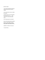
Atma-Sphere Music Systems
St. Paul, MN 55105
Phone: 651-690-2246
FAX: 651-699-1175
http://www.atma-sphere.com
ATMA-SPHERE® MUSIC PREAMPLIFIER
Model MP-1 Mk II
OWNER'S MANUAL
Please study this document carefully before using equipment
CONGRATULATIONS!
You have purchased one of the world's finest preamplifiers and certainly one of the most unique. It was over fifteen years in development and represents a
level of performance that others will be struggling to achieve for years to come. At the time of this writing, it is the only fully balanced differential vacuum-tube
design in the world the also supports the 600 ohm standard.
Every part of the preamplifier has been extensively tested and engineered so the product will perform flawlessly for years to come, with little if any service.
Please read the manual carefully and follow the instructions closely. If you have any questions, do not hesitate to contact your dealer or ATMA-SPHERE®
MUSIC SYSTEMS. Here's to many years of happy listening!
Sincerely,
Ralph Karsten
ATMA-SPHERE® MUSIC SYSTEMS, 160 So. Wheeler St., St. Paul, MN 55105
651-690-2246 FAX: 651-699-1175
LIMITED WARRANTY ON ATMA-SPHERE® MUSIC SYSTEMS PRODUCTS
This warranty on your ATMA-SPHERE® MUSIC SYSTEMS product, which is distributed and warranted by ATMA-SPHERE® MUSIC SYSTEMS, shall
remain in effect for two (2) years from the date of consumer purchase, provided the enclosed registration form is completed and returned to ATMASPHERE® MUSIC SYSTEMS within ten days of purchase.
WHAT IS COVERED:
Except as specified below, this warranty covers all defects in materials and workmanship. The following are NOT covered by the two year limited warranty:
* Tubes are covered for 90 days, with the following exclusions, as per the rest of the warranty:
* Damage occurring during shipment (present claims to carrier).
* Damage resulting from failure or inability to follow proper
instructions.
* Damage resulting from the performance of repairs or
modifications by other than ATMA-SPHERE® MUSIC SYSTEMS.
WHAT WE WILL PAY FOR:
ATMA-SPHERE® MUSIC SYSTEMS will pay for all labor and material expenses for repairs covered by this warranty.
HOW TO OBTAIN WARRANTY SERVICE:
If your unit requires repairs covered by this warranty, you MUST obtain a return authorization number from ATMA-SPHERE® MUSIC SYSTEMS. You are
responsible for transporting the unit to ATMA-SPHERE® MUSIC SYSTEMS, 160 So. Wheeler St., St. Paul, Minn. 55105. You must pay the initial shipping
charges, but ATMA-SPHERE® MUSIC SYSTEMS will pay the return charges, if the repairs are covered by the warranty. All products MUST be shipped in
the original carton(s) or in replacement cartons supplied by ATMA-SPHERE® MUSIC SYSTEMS. Contact ATMA-SPHERE® MUSIC SYSTEMS for
replacement cartons and cost.
LIABILITY IS LIMITED TO THE REPAIR OR REPLACEMENT, AT OUR OPTION, OF ANY DEFECTIVE PRODUCT AND SHALL IN NO EVENT INCLUDE
INCIDENTAL OR CONSEQUENTIAL DAMAGE OF ANY KIND.
This warranty is not transferable. Implied warranties of merchantability and fitness for a particular purpose are limited in duration to the length of this
warranty. This warranty sets forth all expressed warranties made with regard to the above-referenced product. We neither assume nor authorize any other
liability in connection with the sale or any shipment of products. This warranty gives you specific legal rights and you may also have other rights which vary
from state to state. We reserve the right to make changes and improvements in our products without incurring any obligation to similarly alter products
previously purchased.
MUSIC PREAMPLIFIER SET-UP AND OPERATION
Unpack the preamplifier and its power supply carefully and save the packaging containers for future shipment if required. Warranty may be void if the unit is
shipped in a different container. If you do not have a container, contact ATMA-SPHERE® MUSIC SYSTEMS for a replacement. The replacement container is
$30.00.
Place the tubes in the appropriate sockets as shown in the tube chart elsewhere in this manual. There is no tube in the power supply.
During operation, the MP-1 gets hot! Adequate ventilation is mandatory. If the preamplifier is to be placed in a shelf or rack mount system, allow for at least 2
inches of open space above the power supply and head unit. Make sure that the preamplifier is at least a foot away from the power supply, to avoid hum
problems.
After the preamplifier and supply are properly positioned, make sure that the main power switch is in the OFF position. Connect the umbilical cable from the
power supply to the head unit. The connector operates by lining up the correct key channels and then pushing on it gently while turning the knurled threaded
locking ring. It is keyed so that insertion is possible only one way. You may now plug in the power supply. The "POWER AVAILABLE" LED should now light.
Connect the cables for the various components to be used with the preamplifier.
The MP-1 does not use a muting circuit! Allow the preamplifier to warm up and stabilize before energizing your power amplifiers. A muting circuit is
not used as it would interfere with the servo-loop operation in the output section of the preamp. Its presence in the circuit would be audible as well. Although
the DC offsets generated during warmup are low level, this may be a problem for some amplifiers and speakers.
══════════════════════════════════════════════════════════════════════════════
WARNING! DO NOT TURN ON THE AMPLIFIERS IN YOUR SYSTEM UNTIL THE PREAMPLIFIER IS WARMED UP AND STABILIZED! DAMAGE TO
SPEAKERS, AMPLIFIERS OR BOTH MAY RESULT!
══════════════════════════════════════════════════════════════════════════════
Get in the habit of turning down the volume or switching to an unused input anytime you turn your amplifier on, when you change a record, etc.
After the preamplifier is turned on, it takes about 30 seconds before it is ready for use. During the warmup of the preamplifier, one or both of the "DC
OFFSET" LEDs on the front panel may light up. This indicates that the servo circuit has detected a DC voltage at the output of the preamp and is trying to
correct it. If the indicator stays lit for more than a minute, a fault is indicated and the preamplifier must be turned off immediately to prevent
damage to associated equipment. The preamplifier will sound significantly better after about 45 minutes of operation.
OPERATING NOTES
Normally the preamplifier can be left on all the time. Adequate ventilation is required in any event. If the unit is operated continuously, have the tubes tested
once every six months. The unit will sound substantially better three hours after turn-on.
It takes time to break in the internal wiring of the MP-1. Therefore it will sound better with use. This is true of all inputs. Thus if an unused input is put to use,
expect it to require a break-in period, even if the preamp has been in use for a long time.
The MP-1 may be used with a low impedance (600 ohm) load at the input of the power amplifier. Such practice can reduce hum and buzz. An optional
terminator is available from Atma-Sphere for amplifiers without this provision.
Invariably you will have to adjust the GAIN TRIM for proper soundstage effect, because the MP-1 is a zero feedback design. Operate the control SLOWLY.
The GAIN TRIM controls are not in the audio path. They may generate a temporary DC offset while they are operated. This effect will vary depending on the
balance of the sections in the 6SN7 used in the high level section.
Due to the low impedance operation of the MP-1, cable quality between the preamplifier and power amplifier is usually unimportant. You may hear
differences in the cables, but they will be minor compared to the differences you may be used to hearing in single-ended cables. Thus we have no
recommendation for cables to be used between the preamplifier and power amplifier. On the other hand, the input cables may be very critical, depending on
the source.
PHONOGRAPH HOOKUP
Almost all phonograph cartridges are balanced sources. Thus the MP-1 allows you to set up your turntable as a fully-balanced source, with considerable
sonic advantage. For best results, follow the connection scheme outlined below:
1) Use a cable that has two signal conductors PLUS a shield for each channel. The two conductors are for the plus and minus outputs of the cartridge, and
the shield connection becomes the tone arm/turntable ground connection and is common to BOTH channels.
2) Pin number one of any XLR connection should always be ground as per industry standard.
3) Pin two of the XLR phono input corresponds to the "+" or non-inverting output of the cartridge, and pin three is the "-" or inverting output of the cartridge.
Absolute system phase can be corrected from the front panel.
4) There is no need for an independent ground wire from the arm to the preamp.
If you set up the cable correctly, there will be NO hum whatsoever, even if the cartridge output is too low for the preamp. Many tone arms use a five pin
connector that plugs into the bottom of the arm. If this is the case in your system, you may order a tone arm cable with the right connections from almost any
cable manufacturer. If your arm has RCA connectors at the output, an adaptor cable can be made that will work. The shield connection of the RCA must
become the connection to pin 3 of the XLR connector, and the tone arm ground connection should be made as described above. ON NO ACCOUNT should
you allow the shield connection of the RCA to become the shield for the cable, as this will result in a loud hum.
The cartridge loading is achieved by installing resistors on the loading terminal on the rear panel. A screwdriver is all that is needed for attachment. You will
have to experiment to obtain the correct value. One hundred ohms is common with many low output cartidges since the early 1990's.
RF problems may be encountered if the tone arm tube is not grounded. RF beads installed in the interconnect cable can sometimes alleviate this problem.
The trick is to eliminate the RF before it gets into the preamplifier, so treat the ground connection with RF beads also. For best results, the phono cable
should be shielded.
High-Level Hookup
The auxiliary inputs are high impedance. Thus you may use any input as a source for the MP-1. If you are using a low impedance source, a low impedance
termination is recommended for better sound. A single-ended source can also be used, by applying the signal between either pin two or pin three of the input
XLR, and ground. The unused input (pin three or pin two, respectively), may have to be shorted out to prevent noise. Pin two of all the XLR inputs is the
noninverting input, per industry standard.
The tape outputs are high impedance. Use a high-quality cable for best results, and keep the cable as short as possible. The minimum drive impedance is
10K-ohms.
The tape monitors are a single-ended, non-inverting, high impedance input.
NOTE: the INVERT switch will not function in one position if a single-ended input is used (and does not work in the 'invert' position with the tape monitors).
NOTE: Use of NOS tubes may result in inferior performance. There are many counterfeit tubes on teh market, and many that are advertised as NOS tubes
when in reality they are used. Only buy from a reputable vendor, with proper assurance that the tubes can be returned if they are unsatisfactory! We advise
that you do not go overboard with NOS tube types, as the prices paid for the results can be high compared to other changes you can make, fleeting or both.
Of course there are exceptions, but especially in the case of the phono tubes, the investment is often not worthwhile.
MP-1 tube locations 8/98
NOTES ON TUBES
1) The 12AT7s in the upper left of each board
are the most critical for low noise phono
operation.
2) The constant current sources are outside of
the signal path.
3) Matched sections in the frontmost 6SN7 of
the preamp will reduce noise
during
operation of the front panel GAIN TRIM
control.
4) Tube damping rings are recommended.
5) Do not remove tubes while unit is operating.
Hazardous or lethal voltages are present!
(Phono tubes can be changed, by the more
daring, with the volume control turned down.)
6) NEVER use Tweek® on vacuum tubes.
7) Long live analog!
TROUBLESHOOTING TIPS
Front panel LEDs on the power supply don't light up: Check the rear panel fuse and verify that the power cord is plugged in.
Buzz, hum and/or RF interference: Make sure that the power cord is plugged into a properly grounded outlet and that no other equipment in the system is
grounded (resulting in a ground loop). Sometimes RF can get into the phonograph through poorly shielded wiring in or from the tone arm. This is more
common with straight-tracking arms. Small capacitors may have to be installed between the inputs and ground. See previous section on Phonograph
Hookup.
Distortion: Check the output tubes (6SN7, upper right in diagram) and the associated 6SN7 in front for defects. If any of the output pins of the main output
XLR connectors other than pin one is at ground potential, distortion may result.
One or both channels out: There are two fuses located on the right side of the power supply circuit board (as you face the front of the unit), one for each
channel. Replace with the same type slow-blow fuse (.75 Amp for 117 Volt units, .35 Amp for 230 Volt units). If you are not qualified, do not remove the
cover. Hazardous or lethal voltages are present with the cover removed. Refer servicing to qualified service personnel.
Both channels out, intermittent noise or thumping in both channels: Power supply tube (6080) is loose, defective or not installed.
Low output from one channel: Check tubes.
DC Offset LED lit up continuously: Check the 6SN7s (upper right two in diagram) in the channel associated with the LED. If good 6SN7s still lit the LED,
replace the 6080/6AS7A regulator tube. If the LED remains lit, replace the TLO82 opamp ICs on the power supply board by the regulator tube AND the same
ICs inside the head unit by the 6SN7s. They are in sockets and the ICs are availble from Radio Shack or other electronic supply houses. REPLACE the
6080/6AS7A EVERY SIX MONTHS IF THE UNIT IS ON ALL THE TIME. Arc-over failure of the regulator tube will damage all the ICs in the unit.
NEVER, EVER, USE TWEEK® ON TUBE SOCKETS! Tweek® is an organic compound and is capable of forming resistance paths if it breaks down.
If none of these suggestions help, please contact your dealer or ATMA-SPHERE® MUSIC SYSTEMS.
MORE TIPS AND TWEAKS
When ordering from any source, specify tubes for a differential circuit (matched tube sections). The 12AT7s at the input of the phonograph section and the
6SN7 at the input of the high-level section (lower front in diagram) are perhaps the most audible.
Harmonics of the powerline frequency have been shown to be far more problematic for good sound then all other types of powerline problems (RF, spikes,
etc.) put together. Be sure that the conditioner you use can filter line frequency harmonics, particularly the fifth (300 Hz on 60Hz line).
The power cord can have audible effects! A good cable is recommended.
The Sound Anchors equipment stand is the finest we have seen. It is highly recommended. Use it in conjunction with the Ultra Resolution Technologies
vibration-damping platform. Nav-Com Silencers or other anti-vibration pads are also recommended. Tube damping rings are highly recommended.
Most cartridges with more than .2mv seem to work fine. The higher the output the better, tempered with a musical presentation. Some recommended
choices: The Grado Statement and Master Reference, Lyra series (includes the Helicon cartridge), Van Den Hul and Micro Benz. There are of course many
others.
NOTES
WARRANTY REGISTRATION FORM
IMPORTANT: This form must be filled out and returned to ATMA-SPHERE® MUSIC SYSTEMS within 10 days of purchase to validate the warranty! Please
type or print clearly.
___________________________________________________________________________
NAME
Address
_________________________________________________________________________
City or town
Country
________________________________________State__________zipcode____________
_________________________________________________________________________
Name of dealership
Model
__________________________________________________________________
____________Date of purchase_________________serial #___________price paid_____________
Optional section for our records and information:
Comments concerning your dealer
__________________________________________________________
_____________________________________________________________________________
_____________________________________________________________________________
Comments concerning this product
_________________________________________________________
_____________________________________________________________________________
_____________________________________________________________________________
_____________________________________________________________________________
_____________________________________________________________________________
list the components in your system
________________________________________________________
_____________________________________________________________________________
_____________________________________________________________________________
_____________________________________________________________________________
comments, suggestions
_________________________________________________________________
_____________________________________________________________________________
_____________________________________________________________________________
_____________________________________________________________________________
MAIL TO: ATMA-SPHERE MUSIC SYSTEMS, 160 So. Wheeler St., St. Paul, MN 55105 USA