1
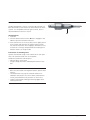
Colibri II. Universal battery power tool
system for use in traumatology, hand
and foot surgery.
Instructions
for Use
This publication is not intended for
distribution in the USA.
Instruments and implants
approved by the AO Foundation
Contents
Introduction
General Information
3
Colibri II
Handpiece
6
Use
8
Attachments
Care and Maintenance
General Information
13
Drill Attachments
15
Screw Attachments
16
Ream Attachments
17
Other Rotating Attachments
19
Saw Attachments
24
Other Attachments
28
General Information
29
Preparation Prior to Cleaning
30
Manual Cleaning Instruction
31
Mechanical/Automated Cleaning Instruction
with Manual Pre-cleaning
33
Lubrication
36
Function Control
40
Packaging, Sterilization and Storage
41
Repairs and Technical Service
43
Disposal
44
Colibri II
Instructions for Use
DePuy Synthes
1
Contents
Troubleshooting
45
System Specifications
47
Accompanying Documents
Electromagnetic Compatibility
Ordering Information
57
Warning
This description alone does not provide sufficient background for the direct use of
the product. Instruction by a surgeon experienced in handling this product is highly
recommended.
2
DePuy Synthes
53
Colibri II
Instructions for Use
Introduction
General Information
Intended use
The Colibri II is a battery-driven power tool for use in traumatology and foot surgery, involving surgical procedures such as
drilling, burring, reaming, pin and wire placement, cutting of
bone and hard tissue.
Safety instructions
The Colibri II is only to be used for patient treatment after
careful consultation of the instructions for use. It is recommended that an alternative system is available to use during
application, as technical problems can never be completely
ruled out.
The Colibri II is designed for use by physicians and trained
medical personnel.
Efficiently working cutting tools are the basis for successful
surgery. Therefore, it is mandatory to check used cutting
tools after every use for wear and/or damage and to replace
them if necessary. We recommend using new Synthes cutting tools for every surgery. Cutting tools must be cooled
with irrigation liquid to prevent heat necrosis.
The user of the product is responsible for proper use of the
equipment during surgery.
If the Colibri II is used in conjunction with an implant system,
make sure to consult the corresponding “Technique Guide”.
For important information regarding electromagnetic compatibility (EMC), please refer to the chapter “Electromagnetic
Compatibility” in this manual.
DO NOT use any component if damage is apparent.
DO NOT use any component if the packaging is damaged.
DO NOT use this equipment in the presence of oxygen, nitrous oxide or a mixture consisting of flammable anesthetics
and air.
To ensure the proper operation of the tool, only use Synthes
original accessories.
Before the first and every subsequent use, power tools and
their accessories/attachments have to run through the complete reprocessing procedure. Protective covers and foils
must be fully removed before sterilization.
For the tool to function properly, Synthes recommends cleaning and servicing it after each use in accordance with the
process recommended in the chapter “Care and Maintenance”. Compliance with these specifications can considerably extend the service life of the tool. Only use Synthes oil
(519.970) to lubricate the tool.
The tool is classified as type BF against electrical shock and
leakage current. The tool is suitable for use on patients in accordance with IEC 60601-1.
To ensure the proper operation of the tool, Synthes recommends annual maintenance by a Synthes service center. The
manufacturer shall assume no responsibility for damage resulting from improper operation, neglected or unauthorized
maintenance of the tool.
Precautions:
– To avoid injuries, the locking mechanism of the tool has to
be activated before every manipulation and before placing
the tool back down, i.e. the mode switch has to be in OFF
position.
– The tool may only be operated with a fully charged battery. To do this, ensure that the battery is charged in good
time. We recommend that the battery is replaced into the
charger immediately after surgery.
– The batteries may never be sterilized. This would destroy
the battery with possible secondary damage.
– Should the machine drop on the floor and have visible defects, do not use it anymore and send it to the Synthes
service center.
Colibri II
Instructions for Use
DePuy Synthes
3
Introduction
General Information
Accessories/scope of delivery
The Colibri II consists of a handpiece, one or several battery
casings and batteries and a range of attachments and accessories designed for the system.
For the system to operate properly, only Synthes cutting tools
should be used.
Special auxiliaries such as cleaning brushes and Synthes oil
are available for cleaning and servicing the system. No
oils from other manufacturers must be used. Only Synthes oil
(519.970) must be used.
Lubricants with other compositions can cause jamming, can
have a toxic effect or can have a negative impact on the
sterilization results. Only lubricate the power tool and the attachments when clean.
Synthes recommends the use of the specifically designed
Synthes Vario Case (68.001.255) and of the specifically
designed Washing Basket (68.001.610) to sterilize and store
the system.
The following components are essential to ensure proper
operation:
– Handpiece (532.101)
– Battery Casing (532.132)
– Battery (532.103)
– Sterile Cover (532.104)
– Universal Battery Charger II (05.001.204)
– At least one attachment of the system
Please refer to the end of these Instructions for Use for an
overview of the components of the system.
Storage and transport
Please use the original packaging for dispatch and transport.
If this is no longer available, please contact the Synthes office.
4
DePuy Synthes
Colibri II
Instructions for Use
Warranty
The warranty for the tools and accessories does not cover
damage of any kind resulting from improper use, damaged
seals or improper storage and transport. The manufacturer
does not accept liability for damage resulting from repairs or
maintenance carried out by unauthorized sites.
Explanation of the general symbols used
Caution
Read the provided Instructions for Use before operating the device.
2
Reuse or reprocessing (e.g. cleaning and resterilization) may compromise the structural integrity of the
device and/or lead to device failure, which may result
in patient injury, illness or death.
Consult the Instructions for Use before operating the
device.
The device is classified as type BF against electrical
shock and leakage current. The device is suitable for
use on patients according to the standards defined by
CSA 601.1, IEC 60601-1 and UL 60601-1.
IEC 60601-1:2005, ANSI/AAMI ES60601-1 (2005),
CAN/CSA-C22.2 No. 60601-1 (2008)
Furthermore, reuse or reprocessing of single use devices may create a risk of contamination e.g. due to
the transmission of infectious material from one patient to another. This could result in the injury or
death of the patient or user.
Synthes does not recommend reprocessing contaminated products. Any Synthes product that has been
contaminated by blood, tissue and/or bodily
fluids/matter should never be used again and should
be handled according to hospital protocol.
Do not immerse device in liquids.
10PB
Colibri II
With regard to electrical shock, fire, mechanical hazards, only in accordance with UL 60601-1 and
CAN/CSA C22.2 No. 601.1.
IEC 60601-1:2005, ANSI/AAMI ES60601-1 (2005),
CAN/CSA-C22.2 No. 60601-1 (2008)
Even though they may appear undamaged, the products may have small defects and internal stress patterns that may cause material fatigue.
Temperature
The device meets the requirements of directive
93/42/EEC for medical devices. It is authorized
0123
by an independent notified body for which it bears
the CE symbol.
Li-Ion
Relative humidity
This device contains Lithium-Ion batteries that should
be disposed of in an environmentally friendly manner.
The European Battery Directive 2006/66/EC applies to
this device. See section “Disposal” on page 44.
Precaution: Risk of fire, explosion and burns. Do not disassemble, crush, heat above 100 °C or incinerate the battery
cells.
Do not reuse
Products intended for single use must not be reused.
Atmospheric pressure
S9
Duty cycle type according to IEC60034-1
IPX4
Ingress protection rating according to IEC 60529
Colibri II
Instructions for Use
DePuy Synthes
5
Colibri II
Handpiece
1
2
3
4
5
6
7
8
Attachment coupling
Trigger for speed regulation
Trigger for switching to reverse/oscillating drilling
Mode selector switch
Battery pack (battery casing with inserted battery)
Release buttons for attachment
Release buttons for battery casing
Knob for the battery casing cover
6
1
4
3
2
Safety system
The Colibri II is equipped with a safety system that prevents
the machine from being unintentionally started. To lock and
unlock the tool, turn the mode selector switch 4 to the appropriate setting on the front plate of the handpiece: OFF,
or ON position.
Protective systems
The Colibri II is equipped with three protective systems:
– A thermal overload safety system that shuts off the tool if
it becomes too hot during use. After cooling, the tool can
be used again.
– An exhaustive discharge protection ensures that the battery does not completely discharge. This protects the
battery and extends its life.
– An internal fuse in the battery that blows in case of
unintended short cut. This prevents excessive heat, fire or
explosion. If this happens, the battery can not be used
anymore.
7
5
8
Speed and rotational direction control
Mode selector switch in the ON position
The bottom trigger 2 gradually controls the forward speed
(up to approx. 1440 rpm with the AO/ASIF quick coupling).
When the bottom and top triggers 2 and 3 are pressed at
the same time, the tool immediately switches to reverse.
When the bottom trigger 2 is released, the tool immediately
stops.
6
4
3
2
6
DePuy Synthes
Colibri II
Instructions for Use
6
Mode selector switch in the oscillating drilling position
( )
When the bottom and top triggers 2 and 3 are pressed at
the same time, the tool immediately switches to oscillating
rotation. When the top trigger 3 is released, the tool returns
to normal forward rotation.
Compatibility between Colibri and Colibri II
Existing Colibri battery packs are compatible with
Colibri II handpiece
The small 12 VDC battery pack of the Colibri (532.003 with
battery casing 532.002) as well as the large 14.4 VDC battery pack (532.033 with battery casing 532.032) can both be
used with the new Colibri II handpiece (532.101).
Existing Colibri handpiece is compatible with Colibri II
battery pack
The existing Colibri handpiece (532.001) can be used with
the new battery pack of the Colibri II (532.103 with battery
casing 532.132).
Important:
– The information contained in this Information for Use concerns the Colibri II system. For more information on the
Colibri articles, please refer to the Colibri Instructions for
Use (036.000.173).
– To prevent injury, the machine must be locked with the
mode selector switch 4 when coupling and removing
attachments and tools, and before laying it down (see
page 6).
– Always check correct functioning before use on patient.
– Always have a back-up system to prevent problems in
case of deficient system.
– Never place the Colibri II on a magnetic surface since the
machine might start unintentionally.
– Always check its functioning before use.
– Pay particular attention to all the instructions in the individual sections that are identified with “Precaution”.
– Components that are no longer useful must be disposed
of in accordance with the local and national regulations.
– Always wear personal protective equipment (PPE) including safety goggles when working with the Colibri II system.
Colibri II
Instructions for Use
DePuy Synthes
7
Colibri II
Use
Before initial use, brand-new tools and accessories must
undergo the entire reprocessing process and the batteries
should be charged. Completely remove protective caps
and films.
Inserting the battery in the battery casing
To ensure sterility, the battery is inserted into the battery casing by two people, one of whom is wearing sterile garments:
1. The person with the sterile garments holds the sterile battery casing. If the casing is not opened, the same person
presses the central button to unlock (Fig. 1), turns the lid
sideways (90°) as indicated by the arrow (Fig.2) and pulls
to open (Fig. 3). Leave the locking mechanism swung outward.
2. The person wearing the sterile garments places the sterile
cover on the battery casing (Fig. 4) and checks if it is
seated correctly. The sterile cover ensures that the unsterile battery does not contact the outside of the sterile casing.
8
DePuy Synthes
Colibri II
Instructions for Use
Figure 1
Figure 2
Figure 3
Figure 4
3. The person not wearing sterile garments carefully guides
the unsterile battery through the sterile cover (Fig. 5). As
an orientation, the two symbols of the battery and the
sterile cover should face each other (Fig. 6). The same person presses it completely into the battery casing to ensure
a correct seat (Fig. 7). This person may not contact the
outside of the battery casing.
4. The person not wearing sterile garments grasps the
flanges on the sterile cover and removes it from the battery casing (Fig. 8).
5. The person wearing the sterile garments closes the casing
cover from the outside without contacting the battery
or the inside of the casing. After having closed the casing
cover, turn the lid sideways (90°) until it clicks.
Figure 5
Figure 6
Figure 7
Figure 8
Colibri II
Instructions for Use
DePuy Synthes
9
Colibri II
Use
Precautions:
– Normally, one battery is sufficient for one surgery. For
safety, two battery packs (battery casing with the battery)
should be kept ready ensuring fast intraoperative changing of batteries under sterile conditions if necessary.
– Never open a battery casing intraoperatively to insert a
new battery. Always replace the whole battery pack by
another battery pack which should have been prepared
before the start of the surgery.
– If the unsterile battery contacts the outside of the casing,
the casing must be resterilised before being used in the
OR.
– To close the casing cover, press it firmly to ensure that it is
completely closed (Fig. 9 and 10) so that the locking
mechanism properly engages. Always control that the
cover is totally closed before using the system.
– Sterilize the sterile cover after each use to ensure aseptic
conditions when inserting the unsterile battery into the
sterile battery casing.
Figure 9
Figure 10
Inserting the battery pack into the power tool
Guide the battery pack (battery casing with inserted battery)
from below into the shaft of the handpiece (Fig. 11). The
shape of the battery casing prevents the battery from being
inserted incorrectly. Check if the battery pack is seated correctly by gently pulling on it.
Removing the battery pack from the power tool
Simultaneously press the release buttons for the battery
casing with one hand (Fig. 12) and use the other hand to
remove the battery pack from the handpiece.
Figure 11
10
DePuy Synthes
Colibri II
Instructions for Use
Figure 12
Charging, storing and using Colibri II batteries
(532.103)
Charging
– The batteries should always be charged before use.
– Only use the Synthes Universal Battery Charger II
(05.001.204) to charge the batteries. Using another
charger can damage the battery.
– Detailed information on the Universal Battery Charger II
can be found in the Instructions for Use (036.000.500)
Precautions:
– Place the battery into the charger immediately after surgery.
– Do not expose batteries to heat or fire. Avoid storage in
direct sunlight.
– Keep the charger and the batteries clean and in a cool
and dry place.
Storage
– When the battery is not being used, store it in the Synthes
Universal Battery Charger II (05.001.204). This will avoid it
from discharging, and the battery will be fully charged
and ready to use.
– Never load the batteries in another charger than the
Universal Battery Charger II (05.001.204).
– The charging station should always be turned on when a
battery is in the charging base. This ensures availability
and prevents discharge.
Use
– Only insert the battery pack directly before using the
Colibri II. This saves battery energy and prevents having
the need to change it during surgery.
– Only use batteries for the indicated purpose. Do not use
any battery which is not designed for use with the equipment.
– Do not transport or store the batteries together with materials that conduct electricity and can cause a short-circuit.
This can damage the battery and generate heat which can
cause burns.
– Never open the battery.
– Do not short-circuit the battery. Do not try to measure the
short-circuit current. This will blow the internal fuse of the
battery.
– Do not apply force to the batteries and do not let them
fall. This will destroy it with possible secondary damage.
– Never use damaged or faulty batteries; they can damage
the power tool.
– Follow the additional information in the chapter “Care
and Maintenance“ starting on page 29 as well as the Instructions for Use of the Synthes Universal Battery
Charger II (036.000.500).
Colibri II
Instructions for Use
DePuy Synthes
11
Colibri II
Use
Using the Colibri II with mains current
The Colibri II can also be operated with mains current. When
the Colibri II is operated with mains current it is classified as
type B against electrical shock and leakage current. When
operated with mains current use the Colibri adapter
(05.001.108) and one of the electrical consoles belonging to
the Electric Pen Drive (05.001.000, 05.001.002 or
05.001.006). The adapter can be inserted into the Colibri II
handpiece and removed like a battery pack (see Fig. 13
and 14). Also follow the Electric Pen Drive’s Instructions for
Use (036.000.800).
Oscillating drilling ( ) mode
To protect soft tissue when drilling and inserting Kirschner
wires, the Colibri II has an electronically controlled oscillating
mode.
To preset the oscillating mode, switch the mode selector
switch to
position.
Pressing the bottom trigger causes the tool to rotate clockwise as usual. Simultaneously pressing the top and bottom
triggers causes the tool to immediately switch to oscillating
mode. The clamped tool oscillates clockwise/anticlockwise.
The speed can be changed by means of the bottom trigger.
After the top trigger is released, the tool returns to normal
clockwise rotation.
Precautions:
– Oscillating mode may only be used with the following
attachments:
– AO/ASIF Quick Coupling (532.013, 05.001.250)
– Chuck (05.001.252, 05.001.253)
– Quick Coupling for Kirschner Wires (532.022)
– Do not use the oscillating mode with the oscillating saw
attachments!
– You can only switch to reverse by turning the mode
selector switch to ON position.
– The maximum cutting speed of a cutting tool is slightly
less in oscillation mode than in normal mode.
12
DePuy Synthes
Colibri II
Instructions for Use
Figure 13
Figure 14
Attachments
General Information
The Colibri II system offers a broad range of attachments.
A wide range of rotating attachments has color-coded rings,
so that they can easily be identified. The table on the
next page lists the different types of attachments available,
the color coding as well as the speed of each attachment.
Mounting the attachments
Insert the attachment into the attachment coupling (Fig. 1).
If the positioning pins do not lock into place right away, twist
the attachment a bit to the right or left until it locks into the
correct position. Check if the attachment is seated correctly
by gently pulling on it.
Removing the attachments
Press the attachment release buttons 6 (see figure on page 6)
simultaneously and remove the attachment from the coupling.
Precautions:
– To prevent injury, the power tool must be switched off
with the safety system (see page 6) during each manipulation.
– Only use original attachments and tools from Synthes.
Damage that arises from using attachments and tools
made by other manufacturers is not covered by the warranty.
– Never use an attachment in reverse mode with an old flexible shaft as this could cause serious injury to the patient.
For this application, we recommend to use exclusively the
attachment without possible reverse motion (05.001.255).
Figure 1
Colibri II
Instructions for Use
DePuy Synthes
13
Attachments
General Information
Article
Number
Drill
Attachments
Product
Max.
Speed
Color
coding
05.001.250 AO/ASIF Quick Coupling
05.001.252 Chuck (Drilling Speed), with Key, clamping range up to ⭋ 4.0 mm
1440 rpm
1440 rpm
Blue
Blue
05.001.253 Chuck (Drilling Speed), with Key, clamping range up to ⭋ 7.3 mm
1440 rpm
Blue
Screw
Attachments
05.001.251 Screw Attachment with AO/ASIF Quick Coupling
384 rpm
Red
Ream
Attachments
532.017
532.018
AO/ASIF Quick Coupling for Medullary Reaming
Hudson Quick Coupling for Medullary Reaming
384 rpm
384 rpm
Red
Red
532.019
Trinkle Quick Coupling for Medullary Reaming
384 rpm
Red
532.020
Trinkle Quick Coupling, modified, for Medullary Reaming
384 rpm
Red
532.015
Quick Coupling for DHS/DCS triple reamers
384 rpm
Red
05.001.254 Chuck (Reaming Speed), with Key, clamping range up to
⭋ 7.3 mm, with reverse motion
05.001.255 Chuck (Reaming Speed), with Key, clamping range up to
⭋ 7.3 mm, without reverse motion
384 rpm
Red
384 rpm
Red
Other
Rotating
Attachments
532.011
532.012
Mini Quick Coupling
J-Latch Coupling
532.022
Quick Coupling for Kirschner Wires
05.001.187 Burr Attachment
Saw
Attachments
Other
Attachments
None
None
960 rpm
None
16000 rpm
None
3840 rpm
None
511.300
Radiolucent Drive
532.021
532.023
Oscillating Saw Attachment
Oscillating Saw Attachment II (Crescentic Technique)
19200 rpm
19200 rpm
None
None
532.026
Large Oscillating Saw Attachment
19200 rpm
None
511.773
511.776
Torque Limiter, 1.5 Nm, for AO/ASIF Quick Coupling
Torque Limiter, 0.8 Nm, with AO/ASIF Quick Coupling
–
–
None
None
511.777
Torque Limiter, 0.4 Nm, with AO/ASIF Quick Coupling
–
None
Technical data is subject to tolerances. Specifications are approximate and may vary
from one device to another or as a result of power supply fluctuations.
14
3840 rpm
3840 rpm
DePuy Synthes
Colibri II
Instructions for Use
Attachments
Drill Attachments
AO/ASIF Quick Coupling (05.001.250)
For tools with an AO/ASIF coupling shaft.
Mounting and removing the tools
Insert the tool into the attachment from the front applying
slight pressure and turning slightly. It is not necessary to operate the coupling sleeve of the attachment.
To disconnect, push the coupling sleeve of the attachment
back and remove the tool.
Chucks
There are two Drill Attachments Chucks available as Drill Attachments for the Colibri II system.
Article number
Clamping range
Spare key
Comments
05.001.252
0 – 4.0 mm
310.932
For drilling
05.001.253
0 – 7.3 mm
510.191
For drilling
Inserting cutting tools
Open the jaws of the Chuck using the appropriate key or by
hand. Insert the shaft of the tool into the open drill chuck
and close it by twisting the chuck. Make sure that the shaft
lies central to the three jaws. Tighten the drill chuck with the
key. Make sure that the teeth of the key engage correctly in
the toothed rim of the chuck.
Removing cutting tools
Open the Chuck with the key and remove the tool.
Precautions:
– Do not use the Colibri II for acetabular reaming.
– Check the cutting tool for wear and/or damage after each
use and replace if necessary.
– To ensure good fixation of the tools, make sure the
toothed rims on the drill chuck and key are not worn.
Colibri II
Instructions for Use
DePuy Synthes
15
Attachments
Screw Attachments
Screw Attachment, with AO/ASIF Quick Coupling
(05.001.251)
Mounting and removing the tools
Insert the tool into the attachment from the front by applying slight pressure and turning slightly. It is not necessary to
operate the coupling sleeve of the attachment.
To disconnect, push the coupling sleeve of the attachment
back and remove the tool.
Precautions:
– Care should be taken when inserting screws with the
drive unit.
– Never fully insert screws with the drive unit. The last turns
or locking should always be done manually.
– Always use an appropriate torque limiting attachment
when putting locking screws into a locking plate.
– Theoretically, it is also possible to use the AO/ASIF Quick
Coupling (05.001.250) to insert screws. However, the
Screw Attachment (05.001.251) has a lower speed and a
higher torque and is therefore more suitable. Screws with
a large diameter may not be able to be inserted with the
AO/ASIF Quick Coupling as the torque may not suffice.
– The attachment is also suitable for application at a lower
rpm and/or higher torque.
16
DePuy Synthes
Colibri II
Instructions for Use
Attachments
Ream Attachments
All Colibri II Ream Attachments provide an
approximative maximal torque of 7.5 Nm
(with battery 532.103).
Quick Couplings for Medullary Reaming
AO/ASIF Quick Coupling (532.017)
Hudson Quick Coupling (532.018)
Trinkle Quick Coupling (532.019)
Trinkle Quick Coupling, modified (532.020)
The Quick Couplings for Medullary Reaming enable the use
of flexible shafts with the appropriate coupling geometry.
Reverse motion, which can damage the flexible shafts, is prevented by a special mechanical system.
Inserting cutting tools into the coupling
Maneuver the unlocking ring on the attachment backward
and insert the tool (such as a drill bit) while rotating it slightly
until it locks into place. Release the ring. Check if the tool is
seated correctly in the coupling by gently pulling on it.
Removing cutting tools
Push the unlocking ring on the attachment backward and remove the tool.
Quick Coupling for DHS/DCS Triple Reamers (532.015)
For DHS/DCS Triple Reamers; can also be used to open the
medullary cavity with most of the Synthes nailing systems.
Mounting and removing the tools
To connect the tool, push the coupling sleeve forward and
then introduce the tool while turning slightly. To disconnect,
push the coupling sleeve of the attachment forward and remove the tool.
Colibri II
Instructions for Use
DePuy Synthes
17
Attachments
Ream Attachments
Chucks
There are two chucks available as Ream Attachments for the Colibri II system.
Article number
Clamping range
Spare key
Comments
05.001.254
0 – 7.3 mm
510.191
For drilling and medullary reaming, with reverse motion
05.001.255
0 – 7.3 mm
510.191
For drilling and medullary reaming, without reverse motion
Inserting cutting tools
Open the jaws of the chuck using the appropriate key or by
hand. Insert the shaft of the tool into the open drill chuck
and close it by twisting the chuck. Make sure that the shaft
lies central to the three jaws. Tighten the drill chuck with the
key. Make sure that the teeth of the key engage correctly in
the toothed rim of the chuck.
Removing cutting tools
Open the chuck with the key and remove the tool.
Warnings:
– During reaming procedure, high torque values must be
provided by the power tool to the reaming head to allow
efficient bone removal. In cases where the reaming head
suddenly is blocked, these high torque values can be
transferred onto the user’s hand, wrist and/or the patient’s
body. In order to prevent injuries it therefore is essential
that:
– the power tool is held in an ergonomical position with a
firm grip.
– if the reamer head blocks, the speed trigger is released
immediately.
– the correct function of the speed trigger (immediate
stop of the system when the trigger is released) is
checked before the reaming process.
– Use the Chuck with Reverse motion (05.001.254) only
with tools that are approved for such use. Otherwise, the
tool may break with subsequent damage.
Precautions:
– Do not use the Colibri II for acetabular reaming.
– Check the cutting tool for wear and/or damage after each
use and replace if necessary.
– To ensure good fixation of the tools, make sure the
toothed rims on the drill chuck and key are not worn.
18
DePuy Synthes
Colibri II
Instructions for Use
Attachments
Other Rotating Attachments
Mini Quick Coupling (532.011)
J-Latch Coupling (532.012)
For tools with a Mini Quick or J-Latch coupling shaft.
Mounting and removing the tools
To connect the tool, pull the coupling sleeve back and then
introduce the tool while rotating slightly.
To disconnect, push the coupling sleeve of the attachment
back and remove the tool.
Quick Coupling for Kirschner Wires (532.022)
Kirschner Wires of any length with a diameter of
0.6 – 3.2 mm can be used with the Quick Coupling for
Kirschner Wires.
J
1. Adjust the Kirschner Wire diameter according to the label
on the adjusting sleeve K. Slightly press the adjusting
sleeve axially against the handpiece and rotate the sleeve.
2. Apply a slight amount of pressure to insert the Kirschner
Wire from the front into the cannulation J. The wire is
held automatically.
3. Adjust the working length by pulling on the wire.
4. To affix the wire, pull the tension lever L against the tool
with your little finger and ring finger. Only pull the tension
lever against the tool as much as necessary. The clamping
force can be varied by pulling and releasing the clamping
lever.
5. Insert the wire into the bone. Apply the clamping force as
long as the wire is advanced.
6. To adjust the grip on the wire, reduce the clamping force
and move the tool to the desired length. Reclamp the wire
by pulling on the tension lever.
K
L
Colibri II
Instructions for Use
DePuy Synthes
19
Attachments
Other Rotating Attachments
Radiolucent Drive (511.300)
The Radiolucent Drive can be used with the Colibri II in combination with the AO/ASIF Quick Coupling (05.001.250) and
the Adapter for the Radiolucent Drive (532.031).
Coupling the Radiolucent Drive to the power tool
Connect the AO/ASIF Quick Coupling to the Colibri II and the
adapter to the Quick Coupling. Position the Radiolucent
Drive as far as it will go over the Quick Coupling and the
adapter and rotate it into the desired working position. Support the drive with your free hand.
(05.001.250)
Inserting the drill bit
Pull the ring on the attachment forward and position the drill
bit inside the coupling as far as it can go while rotating it
slightly. Engage the ring on the attachment back in order to
fix the drill. Check if the drill bit is seated correctly by gently
pulling on it.
Removing the drill bit
Follow the same procedure in reverse order.
20
DePuy Synthes
Colibri II
Instructions for Use
(532.031)
(511.300)
Using the Radiolucent Drive
Before positioning the Radiolucent Drive, align the image
intensifier until the distal locking hole of the medullary nail is
round and easily visible.
After the incision, position the Radiolucent Drive and center
the drill bit tip over the locking hole. On the monitor of the
image intensifier, you can see both the drill bit and the target
rings of the drive.
Swing the drive up and center it precisely so that the drill bit
appears as a round point and the locking hole is visible
around it. The target ring also assists the centering. The locking hole can now be drilled directly.
Colibri II
Instructions for Use
DePuy Synthes
21
Attachments
Other Rotating Attachments
Precautions:
– Grip the coupled Radiolucent Drive tightly when switching
on the power tool, particularly if the power tool is held
face down.
– Only special 3-flute spiral drill bits can be used. Your
Synthes representative will be glad to provide you with additional information on which drill bits can be used.
– Handle the Radiolucent Drive with great care. Do not allow contact between the drill bit and the medullary nail.
– Depending on the setting of the image intensifier, a zone
may appear in the rear of the Radiolucent Drive that is not
radiolucent. However, this does not inhibit aiming and
working with the device.
– To protect the gears, the Radiolucent Drive is equipped
with a slip clutch that disengages in case of an overload
and emits an audible rattling noise.
– The following procedures can cause an overload:
– Correcting the drilling angle when the cutting edges of
the drill bit are completely in the bone.
– Hitting the nail with the drill bit.
– Drilling can continue after making the following corrections:
– Correcting the drilling angle: Remove the drill bit until
the flutes are visible and then restart the drilling.
– Hitting a nail: Remove the drill bit until the flutes are
visible and re-aim the drill bit or exchange the drill bit if
necessary.
22
DePuy Synthes
Colibri II
Instructions for Use
Burr Attachment (05.001.187)
The Burr Attachment is size M. It can be used with Burrs for
Burr Attachments of the Electric Pen Drive and Air Pen Drive
systems. It is compatible with burr types M and L, but it is
recommended to use burrs of size M.
M
Changing burrs
1. Lock unit.
2. Turn the release sleeve for burrs M until it engages in the
UNLOCK position and remove the tool.
3. Insert the new tool as far as possible, turn it slightly until it
locks in place and then turn the release sleeve for burrs
into the LOCK position until it engages. With burrs of size
M, the burr is correctly clamped when the marking M on
the burr shank is no longer visible.
Information on handling burrs
Synthes recommends using a new sterile burr for each operation. This prevents health risks to the patient.
Used burrs present the following risks:
– Necrosis due to excess heat
– Longer cutting time due to reduced performance of the
burr
Precautions:
– Burrs must be cooled with irrigation liquid to prevent heat
necrosis.
– The attachments may only be used with the burrs intended for this purpose or one size above (attachment is
size M, please therefore only use burrs of size M or L).
– Synthes recommends wearing protective goggles when
working with burrs.
Colibri II
Instructions for Use
DePuy Synthes
23
Attachments
Saw Attachments
Precaution: Even if lines and measurements are indicated on
the saws, these articles should not be used as measuring instruments.
Oscillating Saw Attachment (532.021)
Positioning the saw attachment
The attachment can be locked in eight different positions
(45° steps) when coupled: Lock the machine, shove the sliding sleeve N toward the saw blade coupling and rotate the
attachment into the desired position (Fig. 1).
N
Figure 1
Precaution: To prevent injury, always grip the saw attachment with the inserted saw blade from the direction of the
machine.
Changing the saw blade (Fig. 2)
1. Lock the machine.
2. Pull the locking knob O down and turn it counterclockwise.
3. Lift and remove the saw blade.
4. Use a slight amount of pressure to insert the new saw
blade and turn it to the desired position. The desired positions can be offset from each other at 45º angles.
5. Place your thumb on the saw blade coupling to hold the
saw blade and turn the locking mechanism clockwise until
the saw blade is fixed.
6. Unlock the power tool.
Figure 2
Precaution: Saw blades labeled “Single Use” should not be
used repeatedly because of cleaning problems.
Figure 3
24
DePuy Synthes
Colibri II
Instructions for Use
O
Positioning the saw blade
The saw blade can be adjusted in the desired position vertically and horizontally at an angle of 45º (see the earlier sections “Positioning the saw attachment” and “Changing the
saw blade”).
Using the oscillating saw attachment
The saw blade must already be oscillating when the saw is
applied to the bone. Do not apply strong pressure to the saw
blade as this will delay the cutting process and the saw teeth
will catch in the bone. Optimal saw performance is achieved
by moving the power tool slightly back and forth in the
plane of the saw blade so that the blade oscillates beyond
the bone on both sides. Very precise cuts can be made when
the saw blade is guided steadily. Imprecise cuts arise due to
used blades, excess pressure or jamming the saw blade.
Instructions for handling the saw blades
Synthes recommends using a new blade for each operation
to ensure that the saw blade is optimally sharpened and
clean. The following risks are associated with used blades:
– Necrosis caused by excessive heat build-up
– Infection caused by residue
– Extended cutting time due to poor saw performance
Figure 4
Colibri II
Instructions for Use
DePuy Synthes
25
Attachments
Saw Attachments
Oscillating Saw Attachment II (Crescentic Technique)
(532.023)
The Oscillating Saw Attachment II is essentially designed for
use with semicircular saw blades (for example 03.000.313S)
guided by a 1.6 mm Kirschner Wire. It can also be used with
saw blades with a shaft extension (for example 03.000.340S)
for reaching difficult-to-access sites (such as intraoral).
Inserting the saw blade
Pull the saw blade coupling toward the handpiece and insert
the saw blade while rotating it slightly until it locks into the
saw attachment coupling. Release the saw blade coupling
and check that the saw blade is correctly fixed by gently
pulling on the saw blade.
Removing the saw blade
Pull the saw blade coupling towards the handpiece to release
the saw blade.
Precautions:
– The saw attachments may only be used with the handpiece in the ON mode. Never use the attachments in oscillating drilling mode ( ).
– The appropriate surgical technique (036.000.907) should
be observed to ensure the safe and successful application
of the Crescentic Technique.
26
DePuy Synthes
Colibri II
Instructions for Use
70 mm
Large Oscillating Saw Attachment (532.026)
The Large Oscillating Saw Attachment is a specially designed
saw attachment for performing a crescentic saw cut, e.g.
while performing a Tibial Plateau Leveling Osteotomy in the
canine proximal tibia. The attachment is approved for use in
both humans and animals.
Inserting the saw blade
Insert the saw blade in the saw blade coupling and tighten
the screw in the saw blade with the key (532.027) that was
delivered with the attachment or use a T15 StarDrive screwdriver (e.g. 314.115).
Check that the saw blade is correctly in place and properly
tightened.
Mounting the saw attachment
Make sure that the mode switch of the handpiece is in the
OFF position and that the locking sleeve on the saw attachment is set to the unlock position . Insert the saw attachment in any position into the attachment coupling of the
handpiece until it locks into place. To prevent vibrations during operation and to increase the sawing capacity, additional
manual tightening of the attachment onto the handpiece is
required. Turn the locking sleeve into the lock direction until
you feel that the coupling pins engage into the handpiece
(approx. half a revolution).
Precautions:
– Set the mode switch of the Colibri II to the ON position.
Never operate the Large Oscillating Saw attachment in the
oscillating drilling mode ( ).
– Avoid applying high pressure onto the saw blade.
Removing the saw attachment
Turn the locking sleeve to the unlock position
ing both release buttons on the handpiece.
before push-
Colibri II
Instructions for Use
DePuy Synthes
27
Attachments
Other Attachments
Torque Limiter 1.5 Nm (511.773)
Torque Limiter 0.8 Nm (511.776)
Torque Limiter 0.4 Nm (511.777)
Coupling the Torque Limiter to the power tool
Torque Limiters are connected to the Colibri II using the
AO/ASIF Quick Coupling (05.001.251).
Mounting and removing a screwdriver shaft
Insert the screwdriver shaft while rotating it slightly until it
locks into place. To remove it, pull back the unlocking ring
and pull out the screwdriver shaft.
Using the Torque Limiter
Pick up a screw from the corresponding LCP system (Locking
Compression Plate) with the screwdriver shaft and insert it
in the desired plate hole. To insert the screw, start the power
tool slowly, increase the speed and then reduce it again before the screw is fully tightened. The torque is automatically
limited to 1.5, 0.8 or 0.4 Nm. When this limit is reached, you
will hear a distinct clicking. Stop the tool immediately and
pull the tool away from the screw.
Follow the surgical technique of the respective LCP system.
Precaution: The Torque Limiter must be annually serviced
and recalibrated by Synthes. Note the information on the
test certificate in the packaging. The user is responsible for
following the calibration schedule.
28
DePuy Synthes
Colibri II
Instructions for Use
Care and Maintenance
General Information
Power tool units and attachments are frequently exposed to
high mechanical loads and shocks during use and should not
be expected to last indefinitely. Proper handling and maintenance help extend the useful life of surgical instruments.
Gentle care and maintenance with proper lubrication can
substantially increase the reliability and life of the system
components.
Synthes recommends annual servicing and inspection by the
original manufacturer or its exclusive sales outlets. The
manufacturer assumes no warranty for damages arising from
improper use, neglected or unauthorized servicing.
For more information about Care and Maintenance, please
refer to the Colibri II Care and Maintenance Poster
(036.001.383).
Precautions:
– Reprocessing must be performed immediately after each
use.
– Cannulations, unlocking sleeves and other narrow sites require special attention during cleaning.
– Cleaners with pH 7 – 9.5 are recommended. The use of
cleaners with higher pH values can – depending on the
cleaner – cause the dissolution of the surface of aluminum
and its alloys, plastics or compound materials and they
should only be used considering the data regarding material compatibility according to its data sheet. At pH values
higher than 11, the surfaces of stainless steel can also be
affected. For detailed information about material compatibility, see “Material Compatibility of Synthes Instruments
in Clinical Processing“ at www.synthes.com/reprocessing.
– Follow the enzymatic cleaner or detergent manufacturer’s
instructions for use for the correct dilution concentration,
temperature, exposure time and water quality. If the temperature and time are not specified, follow Synthes’
recommendations. Devices should be cleaned in a fresh,
newly-made solution.
– Detergents used on the products will be in contact with
the following materials: stainless steel, aluminum, plastic
and rubber seals.
– Synthes recommends using new sterile cutting tools for
each operation. Refer to “Clinical Processing of Cutting
Tools” (036.000.499) for detailed clinical processing instructions.
Unusual Transmissible Pathogens
Surgical patients identified as at risk for Creutzfeldt-Jakob
disease (CJD) and related infections should be treated with
single-use instruments. Dispose of the instruments used or
suspected of use on a patient with CJD after surgery and/or
follow the current national recommendations.
Important:
– The clinical processing instructions provided have been
validated by Synthes for preparing a non-sterile Synthes
medical device; these instructions are provided in accordance with ISO 17664:2004 and ANSI/AAMI ST81:2004.
– Consult the national regulations and guidelines for additional information. In addition, compliance with internal
hospital policies and the procedures and recommendations of manufacturers of detergents, disinfectants and
any clinical processing equipment is additionally required.
– It remains the responsibility of the processor to ensure
that the processing performed achieves the desired result
using the appropriate properly installed, maintained and
validated equipment, materials and personnel in the processing unit. Any deviation by the processor from the instructions provided should be properly evaluated for effectiveness and potential adverse consequences.
Colibri II
Instructions for Use
DePuy Synthes
29
Care and Maintenance
Preparation Prior to Cleaning
Disassembly
Disassemble device if applicable. Remove all instruments and
attachments from the power tool and remove battery from
casing or handpiece.
To clean the batteries and the charger, wipe them off with a
clean, soft and lint-free cloth dampened with disinfectant or
deionized water (Fig. 1 and 2).
Important: Do not use solvents to disinfect the batteries.
Battery poles must not contact water or solvents: danger of
short circuiting!
Figure 1
Return batteries to charger (05.001.204) after each use
(Fig. 3).
Never immerse the handpiece, lid or attachments in aqueous
solutions or in an ultrasonic bath as this could decrease the
service life of the system.
Handpieces and attachments may be processed using
a) manual cleaning and/or
b) automated cleaning with manual pre-cleaning.
Note: Clean all movable parts in opened position.
Figure 2
Figure 3
30
DePuy Synthes
Colibri II
Instructions for Use
Care and Maintenance
Manual Cleaning Instruction
1. Remove debris. Rinse the device under running cold tap
water for a minimum of 2 minutes. Use a sponge, soft
lint-free cloth or soft-bristled brush to assist in removing
gross soil. For cannulations of the handpiece and attachments, the cleaning brush (519.400) should be used.
Note: Do not use pointed objects for cleaning.
2. Manipulate moving parts. Manipulate all moving parts
such as the triggers, sleeves and switches under running
tap water to loosen and remove gross debris.
3. Spray and wipe. Spray and wipe the device using a neutral pH enzymatic solution for a minimum of 2 minutes.
Follow the enzymatic detergent manufacturer’s directions
for correct temperature, water quality (i.e. pH, hardness)
and concentration/dilution.
4. Clean with detergent. Clean the device manually under
running warm water using an enzymatic cleaner or detergent for a minimum of 5 minutes. Manipulate all moving
parts under running water. Use a soft-bristled brush
and/or soft lint-free cloth to remove all visible soil and debris.
Follow the enzymatic cleaner or detergent manufacturer’s
instructions for use for correct temperature, water quality
and concentration/dilution.
Colibri II
Instructions for Use
DePuy Synthes
31
Care and Maintenance
Manual Cleaning Instruction
5. Rinse with tap water. Rinse the device thoroughly using
cool to lukewarm running water for a minimum of 2 minutes. Use a syringe, pipette or water jet to flush lumens
and channels. Actuate joints, handles and other movable
device features in order to rinse thoroughly under running water.
6. Visually inspect device. Inspect the cannulations, coupling sleeves, etc. for visible soil. Repeat steps 1 – 6 until
no visible soil remains.
7. Final rinse with de-ionized/purified water. Final rinse
with de-ionized or purified water for a minimum of
2 minutes.
8. Dry. Dry device using a soft lint-free cloth or clean compressed air.
32
DePuy Synthes
Colibri II
Instructions for Use
Care and Maintenance
Mechanical/Automated Cleaning
Instruction with Manual Pre-cleaning
Important:
– Manual pre-cleaning prior to mechanical/automated
cleaning/disinfection is important to ensure that cannulations and other difficult to access areas are clean.
– Alternative cleaning/disinfection procedures other than in
the procedure described below (including manual precleaning) have not been validated by Synthes.
1. Remove debris. Rinse the device under running cold tap
water for a minimum of 2 minutes. Use a sponge, soft
lint-free cloth or soft-bristled brush to assist in removing
gross soil. For cannulations of the handpiece and attachments, the cleaning brush (519.400) should be used.
Note: Do not use pointed objects for cleaning.
2. Manipulate moving parts. Manipulate all moving parts
such as the triggers, sleeves and switches under running
tap water to loosen and remove gross debris.
3. Spray and wipe. Spray and wipe the device using a neutral pH enzymatic solution for a minimum of 2 minutes.
Follow the enzymatic detergent manufacturer’s directions
for correct temperature, water quality (i.e. pH, hardness)
and concentration/dilution.
Colibri II
Instructions for Use
DePuy Synthes
33
Care and Maintenance
Mechanical/Automated Cleaning Instruction
with Manual Pre-cleaning
4. Clean with detergent. Clean the device manually under
running warm water using an enzymatic cleaner or detergent for a minimum of 5 minutes. Manipulate all moving
parts under running water. Use a soft-bristled brush
and/or soft lint-free cloth to remove all visible soil and
debris.
Follow the enzymatic cleaner or detergent manufacturer’s
instructions for use for correct temperature, water quality
and concentration/dilution.
5. Rinse with tap water. Rinse the device thoroughly using
cool to lukewarm running water for a minimum of 2 minutes. Use a syringe, pipette or water jet to flush lumens
and channels. Actuate joints, handles and other movable
device features in order to rinse thoroughly under running water.
6. Visually inspect device. Inspect the cannulations, coupling sleeves, etc. for visible soil. Repeat steps 1 – 6 until
no visible soil remains.
7. Load washing basket. Place devices in the specially
designed tray for machine washing supplied by Synthes
(68.001.610). Ensure that all cannulations (handpiece
and attachments), if applicable, are positioned vertically,
i.e. in an upright position as shown.
Note: Specific lid (68.001.602) is available for the washing basket.
34
DePuy Synthes
Colibri II
Instructions for Use
8. Automated cleaning cycle parameters
Note: The washer/disinfector should fulfill the requirements as specified in ISO 15883.
Step
Duration
(minimum)
Cleaning instructions
Rinse
2 minutes
Cold tap water
Pre-wash
1 minute
Warm water (≥ 40 °C); use detergent
Cleaning
2 minutes
Warm water (≥ 45 °C); use detergent
Rinse
5 minutes
Rinse with de-ionized (DI) or purified water (PURW)
Thermal disinfection
5 minutes
Hot DI water, ≥ 93 °C
Dry
40 minutes
≥ 90 °C
9. Inspect the device. Remove all the devices from the
washing basket. Inspect the cannulations, coupling
sleeves, etc. for visible soil. If necessary, repeat the manual pre-clean/automated cleaning cycle. Confirm that all
parts are completely dry.
Mechanical cleaning/disinfection is an additional stress
for power equipment, especially for seals and bearings.
Therefore, systems must be properly lubricated and regularly sent to be serviced (at least once per year).
Colibri II
Instructions for Use
DePuy Synthes
35
Care and Maintenance
Lubrication
The power tool and attachments should be regularly lubricated to ensure a long service life and smooth operation. It is
recommended that the accessible moving parts of the handpiece, the battery casing and attachments are lubricated with
1 drop of Synthes special oil (519.970); distribute the oil by
moving the components. Wipe off the excess oil with a cloth.
For detailed information, please refer to the Colibri II Care
and Maintenance Poster (036.001.383).
Lubricating the handpiece (Fig. 1 and 2)
– Lubricate the trigger shafts and then press the triggers
several times.
– Lubricate the attachment release buttons and then press
the buttons several times.
– Lubricate the battery casing release buttons from both the
outside and inside (see Fig. 2) and then press the buttons
several times.
– Lubricate the mode selector switch and then move it several times.
– Lubricate the attachment coupling.
1
1
1
1
1
1
Figure 1
1
Figure 2
36
DePuy Synthes
Colibri II
Instructions for Use
Lubricating the battery casing (Fig. 3 and 4)
– Place oil on the seal of the cover and then evenly distribute the oil on the seal.
– Lubricate the lock, hinge and knob, then actuate it several
times.
1
Figure 3
1
1
1
Figure 4
Colibri II
Instructions for Use
DePuy Synthes
37
Care and Maintenance
Lubrication
Attachments
All moving parts of all the attachments. Exception: the
Radiolucent Drive (511.300) does not require lubrication.
Chuck (05.001.252 – 05.001.255)
Lubricate the jaws and toothed rim.
Open and close the drill chuck several times.
1
Quick Coupling for Kirschner Wires (532.022)
Lubricate the tension lever and clamping mechanism.
1
Hold the Quick Coupling up and add one drop of oil into the
attachment hole and on the holder of the lever (Fig. 5).
Move the tension lever several times.
Mini Quick Coupling (532.011)
J-Latch Coupling (532.012)
AO/ASIF Quick Coupling (05.001.250/05.001.251)
Quick Coupling for DHS/DCS Triple Reamers (532.015)
Quick Coupling for Medullary Reaming
(532.017/532.018/532.019/532.020)
Lubricate the unlocking ring. Move it back and forth several
times.
Figure 5
Oscillating Saw Attachment (532.021)
Lubricate the locking mechanism and the saw blade coupling.
Open and close the locking mechanism several times.
1
Oscillating Saw Attachment II (532.023)
Lubricate the unlocking sleeve, the tool holder and the attachment coupling. Move it back and forth several times.
Large Oscillating Saw Attachment (532.026)
First lubricate and then move all movable parts:
– Saw blade coupling (slot between the saw blade coupling
and attachment)
– Locking sleeve of the attachment coupling (slots on both
sides)
– Coupling pins
– Opening of the attachment coupling
38
DePuy Synthes
Colibri II
Instructions for Use
1
Figure 6
Precautions:
– To ensure a long service life and reduce repairs, the power
tool and all attachments must be lubricated after each use.
Exception: The Radiolucent Drive (511.300) does not require lubrication.
– The power tool and accessories may only be lubricated
with Synthes special oil (519.970). The composition of the
vapor-permeable and biocompatible oil is optimized for
the specific requirements of the power tool. Lubricants
with other compositions can cause the power tool to jam
and be toxic.
– Only lubricate the power tool and attachments when
clean.
Colibri II
Instructions for Use
DePuy Synthes
39
Care and Maintenance
Function Control
– Visually inspect for damage and wear.
– Check the handpiece controls for smooth operation and
function.
– All movable parts should be moving smoothly. Check that
the triggers do not remain blocked in the handpiece when
pressing on them. Check that no residuals prevent the
movable parts from moving smoothly.
– Check the coupling sleeves of the handpiece and attachments for smooth operation and check for function together with instruments such as cutting tools.
– Check instruments for correct adjustment and functioning
prior to every use.
40
DePuy Synthes
Colibri II
Instructions for Use
Care and Maintenance
Packaging, Sterilization and Storage
Packaging
Put cleaned, dry products into the proper places in the
Synthes case. Additionally, use an appropriate sterilization
wrap or reusable rigid container system for sterilization, such
as a Sterile Barrier System according to ISO 11607. Care
should be taken in order to protect implants as well as
pointed or sharp instruments from contact with other objects
that may damage the surface or the Sterile Barrier System.
Sterilization
Note: For the sterilization of the Colibri II system, Synthes
recommends the use of the specifically designed Synthes
Vario Case (68.001.255) or of the specifically designed
Washing Basket (68.001.610).
Synthes Colibri II system may be resterilized using validated
steam sterilization methods (ISO 17665 or national standards). Synthes’ recommendations for packed devices and
cases are as follows.
Cycle type
Sterilization
exposure time
Sterilization
exposure temperature
Drying time
Saturated steam-forced air
removal (pre-vacuum,
minimum 3 pulses)
Minimum 4 minutes
Minimum 132 °C
Maximum 138 °C
20 – 60 minutes
Minimum 3 minutes
Minimum 134 °C
Maximum 138 °C
20 – 60 minutes
Drying times generally range from 20 to 60 minutes due to
differences in packaging materials (Sterile Barrier System, e.g.,
wraps or reusable rigid container systems), steam quality, device materials, total mass, sterilizer performance and varying
cool down time.
Precautions:
– The following maximum values may not be exceeded:
138 °C over a maximum of 18 minutes. Higher values can
damage the sterilized products.
– Do not accelerate the cooling process.
– Hot air, ethylene oxide, plasma and formaldehyde sterilization are not recommended.
Colibri II
Instructions for Use
DePuy Synthes
41
Care and Maintenance
Packaging, Sterilization and Storage
Storage
Storage conditions for products labeled “STERILE” are
printed on the packaging label.
Packaged and sterilized products should be stored in a dry,
clean environment, protected from direct sunlight, pests and
extremes of temperature and humidity. Use products in the
order in which they are received (“first-in, first-out principle“),
taking note of any expiration date on the label.
42
DePuy Synthes
Colibri II
Instructions for Use
Care and Maintenance
Repairs and Technical Service
The tool should be sent to the Synthes office for repair if it is
faulty or malfunctions. Contaminated products have to run
through the complete reprocessing procedure before being
sent to the Synthes office for repair or technical service.
Faulty devices may not be used. If it is no longer possible or
feasible to repair the tool it should be disposed of (refer to
the following section “Disposal”).
Other than the above-mentioned care and maintenance, no
further maintenance work may be carried out independently
or by third parties.
Synthes recommends the device and accessories such as attachments to be regularly (once a year) serviced by the original manufacturer or an authorized site.
Precaution: The manufacturer assumes no responsibility for
damage resulting from neglected or unauthorized maintenance.
Colibri II
Instructions for Use
DePuy Synthes
43
Care and Maintenance
Disposal
In most cases, faulty tools can be repaired (refer to the previous section “Repairs and Technical Service”).
Li-Ion
This device contains Lithium-Ion batteries that should
be disposed of in an environmentally friendly manner.
The European Battery Directive 2006/66/EC applies to
this device.
Precautions:
– Contaminated products have to run through the complete
reprocessing procedure, so that there is no danger of infection in case of disposal.
– Risk of fire, explosion and burns. Do not disassemble,
crush, heat above 100 °C or incinerate the battery cells.
Please send tools that are no longer used to your local
Synthes representative. This ensures that they are disposed of
in accordance with the national application of the respective
directive. The tool may not be disposed of with household
waste.
44
DePuy Synthes
Colibri II
Instructions for Use
Troubleshooting
Problem
Possible causes
Solution
Handpiece does not start up.
Battery is dead.
Charge the battery or replace it with a
charged battery.
The tool was not cooled off after
sterilization.
Let the tool cool to room temperature.
Mode selector switch is on OFF.
Turn the mode selector switch to ON or
.
No contact between the handpiece
and the battery pack.
Reinsert the battery pack or replace it.
Handpiece does not have enough
power.
Battery is dead.
Charge the battery or replace it with a
charged battery.
Machine stops suddenly.
The machine has overheated (overheating protection is activated).
Wait until the machine has cooled down.
Battery is dead.
Charge the battery or replace it with a
charged battery.
Attachments cannot be coupled to the
unit.
The attachment coupling is blocked
by deposits.
Remove solid objects with a pair of
tweezers.
Precaution: When removing objects,
turn the mode selector switch to OFF.
Tool (saw blade, drill, burr etc.) can not
be coupled or only with difficulty.
Shaft geometry of the attachment or
tool is damaged.
Replace the attachment or tool or send it
to your Synthes service office.
Oscillating saw attachment vibrates too
much.
The saw blade locking mechanism is
not tight.
Tighten the locking knob of the saw
blade coupling.
The mode selector switch is set to
.
Turn the mode selector switch to ON.
The Kirschner wire is inserted in the
handpiece and cannot be moved
forward.
The Kirschner wire was inserted from
the rear.
Lock the machine by turning the mode
selector switch to OFF. Remove the attachment, hold the drive shaft opening
down and shake out the Kirschner wire.
Bone and tool heat up during surgery.
Cutting edges of the tool are blunt.
Replace the tool.
Colibri II
Instructions for Use
DePuy Synthes
45
Troubleshooting
Problem
Possible causes
Solution
It is difficult to close the battery casing.
The battery casing seal has become dry
from repeated cleaning.
Lubricate the seal as described on
page 37.
The battery casing knob is difficult to
turn.
The locking mechanism needs to be
lubricated.
Lubricate the locking mechanism as
described on page 37.
The knob mechanism needs to be
lubricated.
Lubricate the knob mechanism as
described on page 37.
The triggers are difficult to move.
The trigger shafts need to be lubricated. Lubricate the trigger shafts as described
on page 36.
It is difficult to couple the battery casing The battery casing release buttons
to the machine.
need to be lubricated.
Lubricate the battery casing release buttons as described on page 36.
Colibri II is used with the EPD console
and handpiece does not start up.
Console is not switched on or not
connected.
Connect console and/or switch it on.
Handpiece is not connected to console.
Connect handpiece to console.
If the recommended solutions do not work, send the power tool to your local
Synthes service center.
For further technical questions or information on our services, please contact your
Synthes representative.
46
DePuy Synthes
Colibri II
Instructions for Use
System Specifications
Applicable Standards
The device meets the following standards:
IEC 60601-1:2005, 3rd Edition
IEC 60601-1: 1988/ A2:1995, 2nd Edition
UL 60601-1: 2003, 1st Edition
10PB
Colibri II
With respect to electrical shock, fire and
mechanical hazards only in accordance with
UL 60601-1 / CAN / CSA C22.2 No. 601.1
IEC 60601-1:2005, ANSI/AAMI ES60601-1 (2005),
CAN/CSA-C22.2 No. 60601-1 (2008)
Colibri II
Instructions for Use
DePuy Synthes
47
System Specifications
Environmental Conditions
Operation
Temperature
Transportation
40 °C
104 °F
10 °C
50 °F
Relative humidity
90 %
Atmospheric pressure
max. 5000 m
Caution: The machine must not be stored or operated
in explosive atmospheres.
DePuy Synthes
90 %
1060 hPa
Altitude
Colibri II
Instructions for Use
40 °C
104 °F
10 °C
50 °F
10 %
500 hPa
48
60 °C
140 °F
–29 °C
– 20 °F
10 %
Storage
90 %
10 %
1060 hPa
500 hPa
–
1060 hPa
500 hPa
max. 5000 m
Technical Data
Colibri II: 532.101
Continuously adjustable speed:
0 – 3500 rpm
Weight (w. battery):
925 g
Operating voltage:
14.4 VDC
Battery capacity:
1.2 Ah
Battery type:
Li-Ion
Cannulation:
⭋ 3.2 mm
Empty battery charging time:
max. 60 min
Degree of protection against
electrical shock:
BF
Degree of protection against
the penetration of water:
IPX4
Noise level in the operating
position:
approx. 65 dB(A)
Technical data is subject to tolerances. Specifications are approximate and may vary
from one device to another or as a result of power supply fluctuations.
Colibri II
Instructions for Use
DePuy Synthes
49
System Specifications
Duty Cycles: Intermittent
operation type S9,
according to IEC 60034-1
Xs on
Ys off
Cycles
Drilling and tapping threads
and reaming
60 sec
60 sec
9
Burring
60 sec
60 sec
3
Kirschner Wire setting
30 sec
60 sec
6
Sawing
532.021
532.023
532.026
30 sec
15 sec
30 sec
60 sec
60 sec
60 sec
5
4
4
Other attachments
60 sec
60 sec
7
Generally, electrical systems can heat up if in constant use.
For this reason, the handpiece and the attachment should be
allowed to cool for at least 60 seconds (Ys off) following the
time of constant use (Xs on). After a certain amount of cycles
(defined in the above table under “Cycles”), the handpiece
and attachment should be allowed to cool for 30 minutes. If
this is observed, the system will be prevented from overheating and possibly harming the patient or user. The user is responsible for the application and for turning off the system
as prescribed. If longer periods of constant use are required,
an additional handpiece and/or attachment should be used.
These recommendations for times of use for the attachments
of the Colibri II have been determined under average load
with an ambient air temperature of 20 °C (68 °F). Depending
on the cutting tool used and on the load applied, the heat
generation of the handpiece, attachment and/or cutting tool
can vary. Always control the temperature of the system to
prevent overheating and possibly harming the patient or
user.
50
DePuy Synthes
Colibri II
Instructions for Use
Precautions:
– Carefully observe the above recommended duty cycles.
– Always use new cutting tools to prevent the heating up of
the system due to reduced cutting performance.
– Careful maintenance of the system will reduce heat development in the handpiece and the attachments.
– The Colibri II must not be stored or operated in an explosive atmosphere.
– Above mentioned duty cycles can be reduced due to
higher loads applied and due to ambient air temperatures
above 20 °C (68 °F). This needs to be taken into consideration during the planning of the surgical intervention.
– Above mentioned duty cycles can be reduced due to
higher loads applied and due to ambient air temperatures
above 20 °C (68 °F). This needs to be taken into consideration during the planning of the surgical intervention.
Declaration of the emission sound pressure level and the power level according to the EU Directive 2006/42/EC
Annex I
Measurements of the sound pressure level [LpA] are carried out in accordance with standard EN ISO 11202.
Measurements of the sound power level [LwA] are carried out in accordance with standard EN ISO 3746.
Information according to test protocol no.: 1711-5323/03.10, date of testing: 17 February 2011.
Handpiece
Attachment
Tool
Sound Pressure
Level (LpA) in
[dB(A)]
Sound Power
Level (LwA) in
[dB(A)]
Max. daily
exposure time
without hearing
protection
Colibri II
(532.101)
–
–
63
–
>8h
AO/ASIF Quick
Coupling (05.001.250)
–
64
–
>8h
Oscillating Saw
Attachment (532.021)
Saw blade
(532.045)
73
–
>8h
Saw blade
(532.067)
85
94
8h
Saw blade
84
(03.000.313)
92
>8h
Saw blade
85
(03.000.316)
94
8h
Saw blade
83
(03.000.394)
92
>8h
Saw blade
85
(03.000.396)
96
8h
Oscillating Saw
Attachment (532.023)
Large Oscillating Saw
Attachment (532.026)
Colibri II
Instructions for Use
DePuy Synthes
51
System Specifications
Declaration of vibration emission according to the EU Directive 2006/42/EC Annex I
The assessment of the vibration emissions [m/s2] is to be made to the hand-arm system according to EN ISO 8662.
Information according to test protocol no.: 1711-5323/03.10, date of testing: 18 February 2011.
Handpiece
Attachment
Tool
Declaration [m/s2]
Max. daily
exposure
Colibri II
(532.101)
–
–
< 2.5
No limitation
AO/ASIF Quick Coupling
(05.001.250)
–
< 2.5
No limitation
Oscillating Saw
Attachment (532.021)
Saw blade
(532.045)
vertical:
< 2.5
horizontal: < 2.5
No limitation
No limitation
Saw blade
(532.067)
vertical:
3.73
horizontal: 6.58
No limitation
4 h 35 min
Saw blade
(03.000.313)
< 2.5
No limitation
Saw blade
(03.000.316)
6.2
5 h 12 min
Saw blade
(03.000.394)
14.02
1h 1 min
Saw blade
(03.000.396)
18.44
35 min
Oscillating Saw
Attachment (532.023)
Large Oscillating Saw
Attachment (532.026)
52
DePuy Synthes
Colibri II
Instructions for Use
Electromagnetic Compatibility
Accompanying Documents According to
IEC 60601-1-2, 2007, Clause 6
Table 1: Emission
Guidance and manufacturer’s declaration – electromagnetic emissions
The Synthes Colibri II system is intended for use in the electromagnetic environment specified below.
The customer or user of the Synthes Colibri II system should ensure that it is used in such an environment.
Emission test
Compliance
Electromagnetic environment – guidance
RF emissions
CISPR 11
Group 1
The Synthes Colibri II system uses RF energy only
for its internal function. Therefore, its RF emissions are very low and are not likely to cause any
interference in nearby electronic equipment.
RF emissions
CISPR 11
Class B
Harmonic emissions
IEC 61000-3-2
Not applicable
The Synthes Colibri II system is suitable for use in
all establishments, including domestic establishments and those directly connected to the public
low-voltage power supply network that supplies
buildings used for domestic purposes.
Voltage fluctuations/
flicker emissions
IEC 61000-3-3
Not applicable
Colibri II
Instructions for Use
DePuy Synthes
53
Electromagnetic Compatibility
Accompanying Documents
According to IEC 60601-1-2, 2007, Clause 6
Table 2: Immunity (all devices)
Guidance and manufacturer’s declaration – electromagnetic immunity
The Synthes Colibri II system is intended for use in the electromagnetic environment specified below.
The customer or user of the Synthes Colibri II system should ensure that it is used in such an environment.
Immunity test
standard
IEC 60601
test level
Compliance
level
Electromagnetic environment – guidance
Electrostatic
discharge (ESD)
IEC 61000-4-2
±6 kV contact
±8 kV air
±6 kV contact
±8 kV air
Floors should be wood, concrete or ceramic tile.
If the floors are covered with synthetic material,
the relative humidity should be at least 30 %.
Electrical fast
transient/burst
IEC 61000-4-4
±2 kV for power
supply lines
Not applicable
Mains power quality should be that of a typical
commercial or hospital environment.
Surge
IEC 61000-4-5
±1 kV line to line
Not applicable
Mains power quality should be that of a typical
commercial or hospital environment.
Nicht anwendbar
Mains power quality should be that of a typical
commercial or hospital environment.
±2 kV line to earth
Voltage dips, short interruptions and voltage variations
on power supply lines
IEC 61000-4-11
< 5 % UT
(0.5 cycle)
40 % UT
(5 cycles)
70 % UT
(25 cycles)
< 5 % UT for 5 s
Note: UT is the AC mains voltage prior to the application of the test level.
Power frequency (50/60 Hz)
magnetic field
IEC 61000-4-8
3 A/m
54
Instructions for Use
DePuy Synthes
Colibri II
100 A/m
Power frequency magnetic fields should be
at levels characteristic of a typical location in a
typical commercial or hospital environment.
Table 3: Immunity (not life-supporting devices)
Guidance and manufacturer’s declaration – electromagnetic immunity
The Synthes Colibri II system is intended for use in the electromagnetic environment specified below.
The customer or user of the Synthes Colibri II system should ensure that it is used in such an environment.
Electromagnetic environment – guidance
Portable and mobile RF communications equipment should be used no closer to any part of the Synthes Colibri II system,
including cables, than the recommended separation distance calculated from the equation applicable to the frequency of the
transmitter.
Immunity test
standard
IEC 60601
test level
Compliance
level
Recommended
separation distance a
Conducted RF
IEC 61000-4-6
3 Vrms
150 kHz to 80 MHz
Not applicable
d = 0.35 公僓P
150 kHz to 80 MHz
Radiated RF
IEC 61000-4-3
3 V/m
E1 = 10 V/m
(measured 20 V/m)
80 MHz to 800 MHz
d = 0.35 公僓P
E2 = 10 V/m
(measured 20 V/m)
80 MHz to 800 MHz
d = 0.35 公僓P
80 MHz to 800 MHz
Radiated RF
IEC 61000-4-3
3 V/m
800 MHz to 2.5 GHz
80 MHz to 800 MHz
800 MHz to 2.5 GHz
Where P is the maximum output power rating of the transmitter in watts (W) according to the transmitter manufacturer
and d is the recommended separation distance in meters (m).
Field strengths from fixed RF transmitters as determined by an electromagnetic site survey, b
should be less than the compliance level in each frequency range.c
Interference may occur in the vicinity of equipment marked with the following symbol:
Notes:
– At 80 MHz and 800 MHz, the higher frequency range applies.
– These guidelines may not apply in all situations. Electromagnetic propagation is affected
by absorption and reflection from structures, objects and people.
a Possible shorter distances of outside ISM bands are not considered to have a better applicability of this table.
b Field strengths from fixed transmitters, such as base stations for radio (cellular/cordless) telephones and land mobile radios, amateur radio, AM and FM radio broadcast
and TV broadcast cannot be predicted theoretically with accuracy. To assess the electromagnetic environment due to fixed RF transmitters, an electromagnetic site
survey should be considered. If the measured field strength in the location in which the Synthes Colibri II system is used exceeds the applicable RF compliance level
above, the Synthes Colibri II system should be observed to verify normal operation. If abnormal performance is observed, additional measures may be necessary, such as
reorienting or relocating the Synthes Colibri II system.
c Over the frequency range 150 kHz to 80 MHz, field strengths should be less than 10 V/m.
Colibri II
Instructions for Use
DePuy Synthes
55
Electromagnetic Compatibility
Accompanying Documents
According to IEC 60601-1-2, 2007, Clause 6
Table 4: Recommended separation distances
Recommended separation distances between portable and mobile RF communications equipment
and the Synthes Colibri II system
The Synthes Colibri II system is intended for use in the electromagnetic environment in which radiated RF disturbances are
controlled. The customer or user of the Synthes Colibri II system can help prevent electromagnetic interference by maintaining
a minimum distance between portable and mobile RF communications equipment (transmitters) and the Synthes Colibri II
system as recommended below, according to the maximum output power of the communication equipment.
Rated maximum output
power of transmitter
W
Separation distance according to frequency of transmitter
m
150 kHz to 80 MHz
d = 0.35 公僓P
80 MHz to 800 MHz
d = 0.35 公僓P
800 MHz to 2.5 GHz
d = 0.35 公僓P
0.01
4 cm
4 cm
4 cm
0.1
11 cm
11 cm
44 cm
1
35 cm
35 cm
1.4 m
10
1.11 m
1.11 m
4.4 m
100
3.5 m
3.5 m
14 m
For transmitters rated at a maximum output power not listed above, the recommended separation distance d in meters (m)
can be estimated using the equation applicable to the frequency of the transmitter, where P is the maximum output power
rating of the transmitter in watts (W) according to the transmitter manufacturer.
Notes:
– At 80 MHz and 800 MHz, the separation distance for the higher frequency range applies.
– These guidelines may not apply in all situations. Electromagnetic propagation is affected by absorption and reflection from
structures, objects and people.
– An additional factor of 10/3 is used in calculating the recommended separation distance to decrease the likelihood that
mobile/portable communications equipment could cause interference if it is inadvertently brought into patient areas.
56
DePuy Synthes
Colibri II
Instructions for Use
Ordering Information
Drive unit
532.101
Consoles
Colibri II
05.001.002
Basic Console for Electric Pen Drive and Small Electric Drive
05.001.108
Light Adapter, for Colibri (II)
Charger, Battery and Accessories for Battery
532.132
Battery Casing for Nos. 532.101 and 532.110,
with Locking for Lid
532.103
Battery for Nos. 532.101 and 532.110
532.104
Sterile Cover for Nos. 532.101 and 532.110
689.507
Lid (Stainless Steel), size 1/1, for Vario Case
05.001.204
Universal Battery Charger II
68.001.253
Vario Case, size 1/2, for attachments for Colibri (II),
Small Battery Drive (II) and Small Electric Drive
Accessories
68.001.255
Vario Case, size 1/1, for Colibri II and Small Battery Drive II,
without Lid, without Contents
Attachments
689.537
Lid (Stainless Steel), size 1/2, for Vario Case
532.011
Mini Quick Coupling,
for Nos. 532.001, 532.010, 532.101, 532.110 and 05.001.175
519.400
Cleaning Brush for Compact Air Drive, Power Drive, Colibri (II)
and Small Electric Drive
532.012
J-Latch Coupling,
for Nos. 532.001, 532.010, 532.101, 532.110 and 05.001.175
68.001.610
Washing Basket, size 1/1, for Colibri (II) and Small Battery Drive (II)
68.001.602
Lid for Washing Basket, size 1/1
05.001.250
AO/ASIF Quick Coupling,
for Nos. 532.001, 532.010, 532.101, 532.110 and 05.001.175
519.970
Oil Dispenser with Synthes Special Oil, 50 ml
532.024
Cleaning Brush for Oscillating Saw Attachment II (532.023)
05.001.251
Screw Attachment with AO/ASIF Quick Coupling,
for Nos. 532.001, 532.010, 532.101, 532.110 and 05.001.175
310.932
Spare Key for Drill Chuck, clamping range up to ⭋ 4.0 mm
510.191
Spare Key for Drill Chuck, clamping range up to ⭋ 7.3 mm
05.001.252
Chuck (Drilling Speed), with Key, clamping range up to ⭋ 4.0 mm
05.001.253
Chuck (Drilling Speed), with Key, clamping range up to ⭋ 7.3 mm
05.001.254
Chuck (Reaming Speed), with Key, clamping range up to ⭋ 7.3 mm,
with reverse motion
05.001.255
Chuck (Reaming Speed), with Key, clamping range up to ⭋ 7.3 mm,
without reverse motion
532.015
Quick Coupling for DHS/DCS triple reamers,
for Nos. 532.001, 532.010, 532.101, 532.110 and 05.001.175
532.017
AO/ASIF Quick Coupling for Medullary Reaming,
for Nos. 532.001, 532.010, 532.101, 532.110 and 05.001.175
532.018
Hudson Quick Coupling for Medullary Reaming,
for Nos. 532.001, 532.010, 532.101, 532.110 and 05.001.175
532.019
Trinkle Quick Coupling,
for Nos. 532.001, 532.010, 532.101, 532.110 and 05.001.175
532.020
Trinkle Quick Coupling, modified,
for Nos. 532.001, 532.010, 532.101, 532.110 and 05.001.175
532.022
Quick Coupling for Kirschner Wires ⭋ 0.6 to 3.2 mm,
for Nos. 532.001, 532.010, 532.101 and 532.110
05.001.187
Burr Attachment,
for Nos. 532.001, 532.010, 532.101, 532.110 and 05.001.175
532.021
Oscillating Saw Attachment,
for Nos. 532.001, 532.010, 532.101, 532.110 and 05.001.175
532.023
Oscillating Saw Attachment II (Crescentic Technique),
for Nos. 532.001, 532.010, 532.101, 532.110 and 05.001.175
532.026
Large Oscillating Saw Attachment,
for Nos. 532.001, 532.010, 532.101, 532.110 and 05.001.175
532.031
Adapter for Radiolucent Drive,
for Nos. 532.001, 532.010, 532.101, 532.110 and 05.001.175
511.300
Radiolucent Drive
511.773
Torque Limiter, 1.5 Nm, for AO/ASIF Quick Coupling
511.776
Torque Limiter, 0.8 Nm, with AO/ASIF Quick Coupling
511.777
Torque Limiter, 0.4 Nm, with AO/ASIF Quick Coupling
Colibri II
Instructions for Use
DePuy Synthes
57
Ordering Information
Cutting tools
Detailed ordering information on the cuttings tools for the
Colibri II system with original size pictures can be found in
the brochure “Saw blades” (036.000.172).
Detailed ordering information on burrs compatible with the
Colibri II system can be found in the brochure “Burrs for
Electric Pen Drive and Air Pen Drive”, section “Burrs for Burr
Attachments” (036.000.096).
Precaution: Saw blades labeled “Single Use” should not be
used repeatedly due to cleaning problems.
58
DePuy Synthes
Colibri II
Instructions for Use
Colibri II
Instructions for Use
DePuy Synthes
59
60
DePuy Synthes
Colibri II
Instructions for Use
Synthes and Vario Case are trademarks of Synthes, Inc. or its affiliates
Subject to modifications
© Synthes, Inc. or its affiliates
40100206
60087351
This publication is not intended for distribution in the USA.
All technique guides are available as PDF files at
www.synthes.com/lit
0123
SE_476817 AB
02/2013
Synthes GmbH
Eimattstrasse 3
CH-4436 Oberdorf
www.synthes.com
036.001.387
Ö036.001.387öAB}ä