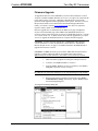
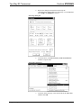
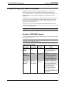
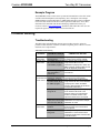
1
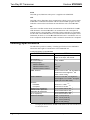
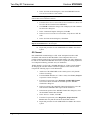
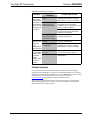
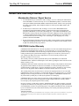
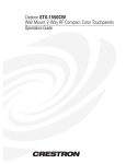
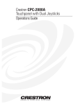
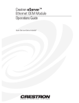
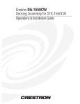
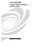
Crestron STRFGWX Two-Way RF Transceiver Operations Guide This document was prepared and written by the Technical Documentation department at: Crestron Electronics, Inc. 15 Volvo Drive Rockleigh, NJ 07647 1-888-CRESTRON All brand names, product names and trademarks are the property of their respective owners. ©2001 Crestron Electronics, Inc. Crestron STRFGWX Two-Way RF Transceiver Contents Two-Way RF Transceiver: STRFGWX 1 Description................................................................................................................................. 1 Functional Description ................................................................................................ 1 Physical Description.................................................................................................... 1 Leading Specifications............................................................................................................... 4 Setup .......................................................................................................................................... 6 Network Wiring........................................................................................................... 6 Preparation for Use...................................................................................................... 7 Identity Codes.............................................................................................................. 7 Firmware Upgrade....................................................................................................... 9 Programming with SIMPL Windows ...................................................................................... 12 Configure STRFGWX Program ................................................................................ 12 Example Program ...................................................................................................... 13 Problem Solving ...................................................................................................................... 13 Troubleshooting......................................................................................................... 13 Further Inquiries ........................................................................................................ 14 Future Updates .......................................................................................................... 15 Future Firmware Upgrades........................................................................................ 15 Return and Warranty Policies .................................................................................................. 16 Merchandise Returns / Repair Service ...................................................................... 16 CRESTRON Limited Warranty................................................................................. 16 Operations Guide - DOC. 5811A Contents • i Crestron STRFGWX Two-Way RF Transceiver Two-Way RF Transceiver: STRFGWX Description Functional Description The STRFGWX is a two-way radio frequency (RF) gateway/transceiver that communicates with the Crestron wireless STX-1550C 2-Way RF Compact Color and STX-1550CW Wall Mount 2-Way RF Compact Color Touchpanels. The STRFGWX receives RF signals from one or more touchpanels (sold separately) and translates the signals into commands for transmission over the Crestron remote control system (herein referred to as the Cresnet system). Feedback signals from the Cresnet system are transmitted from the STRFGWX to the touchpanel(s) for realtime confirmation of commands. Up to 15 touchpanels can communicate with one STRFGWX and, if more touchpanels are needed, more STRFGWXs may be added to the control system. The RF signals can travel from a minimum of three feet up to a maximum of 50 - 75 feet. Additional range can be obtained by using multiple STRFGWX units distributed throughout any particular area or installation. The location of the STRFGWX and the orientation of the antenna are important factors in the RF performance. With the unit located outside of any metal enclosures and the antenna positioned horizontally, pointing straight out of the unit, adjust the antenna to achieve the best range. The range of the unit is also dependent on its placement and the construction of the building in which it is used. Included with the STRFGWX is a 4-pin connector plug to connect to other Cresnet system devices. Also included is an external power pack (PW-1205 for domestic use or PWI-1210 for international use). Physical Description The STRFGWX, shown on the next page, is housed in a black enclosure with silkscreened labels on the front and rear panels. On the front of the unit are five lightemitting diodes (LEDs) for indicating the unit’s status and the RF antenna (not shown for clarity). All other connections are made on the back of the unit. There are four rubber feet on the base of the unit for stability and to prevent slippage. Operations Guide - DOC. 5811A Two-Way RF Transceiver: STRFGWX • 1 Two-Way RF Transceiver Crestron STRFGWX STRFGWX Physical Views 7.07 in (17.95 cm) NET 12VDC .5A NET NET 24 Y Z G CRESTRON ELECTRONICS INC. ROCKLEIGH, N.J. 07647 USA 6.32 in (16.06 cm) RF GATEWAY - 2 WAY RF PWR NET SIG Rx ANTENNA Tx CRESTRON 1.70 in (4.32 cm) STRFGWX STRFGWX Ports The rear panel of the STRFGWX contains the port for operating power and three Cresnet ports. Each has a silk-screened label. Refer to the diagram below and the following descriptions. STRFGWX Rear Panel Ports 12VDC .5A NET NET NET 24 Y Z G CRESTRON ELECTRONICS INC. ROCKLEIGH, N.J. 07647 USA 2 • Two-Way RF Transceiver: STRFGWX Operations Guide - DOC. 5811A Crestron STRFGWX Two-Way RF Transceiver 12 VDC .5 A This direct current (DC) power socket connector is used to supply power via the external power pack. Crestron recommends specific power packs for its devices. The supplied power pack for the STRFGWX is Crestron part number PW-1205 (PWI-1210 for international use). If a power pack other than this Crestron model is obtained, verify that it meets the required specifications and polarity as shown after this paragraph. Power Pack Specifications CRESTRON POWER PACK INPUT SPECS OUTPUT SPECS PW-1205 120VAC~60 hertz (Hz) 12VDC .5A PWI-1210 230VAC~50Hz 12VDC 1A Power Pack Output Connector Polarity NET (Modular Cresnet) These two 6-pin, 6-position RJ11 modular jacks are used to connect the STRFGWX to modular devices in the Cresnet system. Two NET ports are available so that network units can be daisy-chained together. NOTE: Most 6-conductor telephone cables are wired in a crisscross fashion and are not compatible with Crestron equipment. NOTE: All NET connectors, the two modular and the four-wire, can be used simultaneously. NET (Four-Wire Cresnet) This 4-pin connector is used to connect the STRFGWX to other four-wire devices in the Cresnet system. STRFGWX Indicators There are five LED indicators located on the front panel of the STRFGWX. Refer to the diagram below and the descriptions on the next page. The front panel also has a connector where the supplied antenna is attached. The antenna transmits and receives the touchpanel RF signals. STRFGWX Indicators RF GATEWAY - 2 WAY RF PWR NET CRESTRON Operations Guide - DOC. 5811A SIG Rx ANTENNA Tx STRFGWX Two-Way RF Transceiver: STRFGWX • 3 Two-Way RF Transceiver Crestron STRFGWX PWR This LED (green) illuminates when power is supplied to the STRFGWX. NET This LED (yellow) illuminates when communication with the Cresnet system and the STRFGWX is established. Illumination indicates that the SIMPL program currently loaded has a network device defined at the same NET ID code as the STRFGWX. RF These three red LEDs monitor the RF communications of the STRFGWX. The SIG LED illuminates when the STRFGWX is in communication with a touchpanel. If multiple units have been installed to expand the roaming capabilities of a touchpanel, the SIG LED of the STRFGWX that is in communication with the touchpanel will be illuminated, all others are out. The Rx LED illuminates when a command is received from a touchpanel and Tx illuminates when a command is transmitted to a touchpanel. Leading Specifications The table below provides a summary of leading specifications for the STRFGWX. Dimensions and weight are rounded to the nearest hundredth unit. Leading Specifications of the STRFGWX SPECIFICATION Power Requirements Default NET ID RF Communications Operating Ranges Minimum Distance Maximum Distance Indoor Maximum Distance Outdoor SIMPL Windows Crestron Database Firmware STRFGWX Touchpanel CEN/CN-TVAV Update File CNMSX-AV/Pro Update File CNRACKX/-DP Update File ST-CP Update File Dimensions & Weight 1 DETAILS 12VDC, external power pack or 24VDC, 0.125 amps, 3W, network 4F 1 2-Way, 418MHz 3 ft 2 50 to 75 ft 2 150 ft Version 1.30.01 or later 3 with the addition of smwlib70.exe and smwlib70.txt. 3 OR version 1.40.02 or later. 3 Version 12.1.4 or later 3 for SmarTouch Wizard support or 12.1.3 later 3 for regular support (use a CT-1600 model). Version 2.4.1 or later. 4 & 5 Version 5.077.0 or later. 4 & 5 Version 51205V.UPZ or later. 6 Version 51020X.UPZ or later. 6 Version 51020W.UPZ or later. 6 Version 40104S.UPZ or later. 6 Height: 1.70 in (4.32 cm) Width: 7.07 in (17.95 cm) Depth: 6.32 in (16.06 cm) Weight: 2.10 lb (0.95 kg) 7 If changing the default NET ID, do NOT set the NET ID to 1B or the unit will have to be returned to Crestron. 4 • Two-Way RF Transceiver: STRFGWX Operations Guide - DOC. 5811A Crestron STRFGWX Two-Way RF Transceiver 2 The location of the STRFGWX and the orientation of the antenna are important factors in the RF performance. Locate the unit outside of any metal enclosures and position the antenna horizontally, pointing straight out of the unit. Adjust the antenna to achieve the best range. The range of the unit is also dependent on its placement and the construction of the building in which it is used. Installers can run multiple STRFGWX units, which have built-in intelligence so that if both (or several) gateways receive a button press from the touchpanel, only the strongest signals produce an action in the control system. Crestron recommends that the latest firmware be loaded into the STRFGWX and associated touchpanel(s). If the firmware of the STRFGWX is upgraded, the associated touchpanel(s) must also be upgraded at the same time. 3 The latest software version can be obtained from the What’s New page (SIMPL Windows and Crestron Database sections) or Downloads page (SIMPLWIN and CRESDB Libraries) of Crestron’s website. 4 STRFGWXs and touchpanels with later versions of firmware may include features not mentioned in this guide. Newer versions of this guide can be obtained from the Downloads page (MANUAL Library) of Crestron’s website. 5 To utilize firmware upgrade files, a STRFGWX with a firmware version earlier than 1.5.0 must be returned to Crestron. The upgrade files can be obtained from the What’s New page (Touchpanels section) or the Downloads page (TOUCHPNL and UPGRADES Libraries) of Crestron’s website (www.crestron.com). New users are required to register in order to obtain access to the FTP site. Crestron recommends that the latest firmware be loaded into the STRFGWX and associated touchpanel(s). If the firmware of the STRFGWX is upgraded, the associated touchpanel(s) must also be upgraded at the same time. 6 CNX update files are required for either CNMSX-AV/Pro or CNRACKX/-DP. Filenames for CNX update files have a UPZ extension and SmarTouch files are in one EXE or zipped UPZ file. All can be obtained from the What’s New page (Control Systems Update Files section) or Downloads page (OPSYS Library) of Crestron’s website. 7 The weight listed is for the STRFGWX and does not include 4-pin connector plug or external power pack. NOTE: Equipment has been tested and found to comply with the limits for a Class B digital device, pursuant to part 15 of the FCC Rules. These limits are designed to provide reasonable protection against harmful interference in a residential installation. The equipment generates, uses and can radiate radio frequency energy and, if not installed and used in accordance with the instructions, may cause harmful interference to radio communications. However, there is no guarantee that interference will not occur in a particular installation. If this equipment does cause harmful interference to radio or television reception, which can be determined by turning the equipment off and on, the user is encouraged to try to correct the interference by one or more of the following measures: Reorient or relocate the receiving antenna. Increase the separation between the equipment and receiver. Connect the equipment into an outlet on a circuit different from that to which the receiver is connected. Consult the dealer or an experienced radio/TV technician for help. As of the date of manufacture, the unit has been tested and found to comply with specifications for CE marking. Operations Guide - DOC. 5811A Two-Way RF Transceiver: STRFGWX • 5 Two-Way RF Transceiver Crestron STRFGWX Setup Network Wiring NOTE: If making category 5 connections to the Cresnet peripherals, refer to the latest revision of the Cresnet Mini Network CAT 5 Interconnect Drawing (Doc. 5819). This document can be obtained from the Downloads page (CABLES and MANUAL Libraries) of Crestron’s website (www.crestron.com). Search for CAT5.PDF. New users are required to register in order to obtain access to the site. NOTE: Review the latest revision of the Network Modular Cable Requirements (Doc. 5682). This document can be obtained from the Downloads page (CABLES and MANUAL Libraries) of Crestron’s website (www.crestron.com). Search for MODULAR.PDF. When calculating the wire gauge for a particular network run, the length of the run and the power factor of each network unit to be connected must be taken into consideration. If network units are to be daisy-chained on the run, the power factor of each network unit to be daisy-chained must be added together to determine the power factor of the entire chain. The length of the run in feet and the power factor of the run should be used in the following resistance equation to calculate the value on the right side of the equation. Resistance Equation R < 40,000 L x PF Where: R = Resistance (refer to table below). L = Length of run (or chain) in feet. PF = Power factor of entire run (or chain). The required wire gauge should be chosen such that the resistance value is less than the value calculated in the resistance equation. Refer to the table after this paragraph. Wire Gauge Values RESISTANCE (R) WIRE GAUGE 4 16 6 18 10 20 15 22 13 Doubled CAT5 8.7 Tripled CAT5 NOTE: All network wiring must consist of two twisted-pairs. One twisted pair is the +24V conductor and the GND conductor and the other twisted pair is the Y conductor and the Z conductor. NOTE: When daisy-chaining Cresnet units, strip the ends of the wires carefully to avoid nicking the conductors. Twist together the ends of the wires that share a pin on the network connector, and tin the twisted connection. Apply solder only to the ends of the twisted wires. Avoid tinning too far up the wires or the end becomes brittle. Insert the tinned connection into the Cresnet connector and tighten the retaining screw. Repeat the procedure for the other three conductors. 6 • Two-Way RF Transceiver: STRFGWX Operations Guide - DOC. 5811A Crestron STRFGWX Two-Way RF Transceiver Preparation for Use Refer to the hookup diagram below, which shows the STRFGWX connections to the Cresnet system. Other than making the power connection last, complete the connections in any order. NOTE: Refer to “Network Wiring” on page 6 when making connections to the ports labeled NET. Cresnet System Hookup Connections for STRFGWX TO ANY STS OR CRESNET NETWORK DEVICES FOR NORMAL OPERATION OR FOR PROGRAMMING 12VDC .5A NET NET NET 24 Y Z G CRESTRON ELECTRONICS INC. ROCKLEIGH, N.J. 07647 USA FROM EXTERNAL POWER PACK TO CONTROL SYSTEM FOR NORMAL OPERATION OR PROGRAMMING Identity Codes The STRFGWX possesses two distinct types of identity codes: NET ID and RF CHANNEL. These codes are assigned to the unit from Crestron software. Identity Code Every equipment and user interface within the Cresnet system requires a unique NET ID. These codes are recognized by a two-digit hexadecimal number from 03 to FE. The NET ID of the unit must match an ID code specified in the SIMPL Windows program. The NET ID of the STRFGWX is factory set to 4F. The NET IDs of multiple STRFGWXs must all be unique and changed from a personal computer (PC) via SIMPL Windows or VT Pro-e. NOTE: VT Pro-e is a Windows compatible software package for creating Crestron touchpanel screen designs. The method for changing the unit’s NET ID is identical regardless of the software chosen. Complete the following steps to change the NET ID. Operations Guide - DOC. 5811A 1. Attach one of the STRFGWXs to the control system (verify that the software is running). 2. From the SIMPL Windows or VT Pro-e menu, select Tools | Viewport to open the Crestron Viewport. 3. From the Viewport menu, select Functions | Set Network ID. The software checks the baud rate and then opens the “Set Network ID” dialog box. Two-Way RF Transceiver: STRFGWX • 7 Two-Way RF Transceiver Crestron STRFGWX 4. In the “Set Network ID” dialog box, select the STRFGWX from the Current Network Devices text window. CAUTION: If changing the default NET ID, do NOT set the NET ID to 1B or the unit will have to be returned to Crestron. 5. From the Choose the new network ID for the selected device (Hex): text box select the new Net ID for the STRFGWX. 6. Click Set ID to initiate the change. This will display the “ID command has been sent” dialog box. 7. In the “Command Complete” dialog box, click OK. 8. In the Current Network Devices text window, verify the new NET ID code. 9. In the “Set Network ID” dialog box, click Close. NOTE: The new NET ID code may also be verified by selecting Diagnostic | Report Network Devices in the Viewport. 10. Repeat this procedure for each STRFGWX to be added to the Cresnet system. RF Channel Each STRFGWX communicating to a STX-1550C touchpanel must have a RF CHANNEL that matches the RF CHANNEL of the touchpanel. There are 16 possible channels ranging from 0 to F (hexadecimal number). The same channel may be used for more than one STRFGWX when used to expand the roaming capabilities of a touchpanel within any particular area(s) or installation. The RF channel is set from a PC via SIMPL Windows or VT Pro-e but the method for changing the unit’s RF channel is identical regardless of the software chosen. Complete the following steps to set the RF channel. 8 • Two-Way RF Transceiver: STRFGWX 1. Attach one of the STRFGWXs to the control system (verify that the software is running). 2. From the SIMPL Windows or VT Pro-e menu, select Tools | Viewport to open the Crestron Viewport. 3. From the Viewport menu, select Functions | Set RFGWX Channel. The software checks the baud rate and then opens the “RFGWX Channel ID” dialog box. 4. In the top-portion of the “RFGWX Channel ID” dialog box, select the NET ID of the STRFGWX that requires the RF channel set. 5. In the bottom-portion of the “RFGWX Channel ID” dialog box, select the desired RF channel then click OK. 6. In the “Success” window, click OK. 7. From the Viewport menu, select Diagnostics | Report Network Devices and verify that the unit has the desired RF channel. 8. Repeat this procedure for each STRFGWX to be added to the Cresnet system. Operations Guide - DOC. 5811A Crestron STRFGWX Two-Way RF Transceiver Firmware Upgrade To upgrade the firmware of the STRFGWX, a local PC that contains the Crestron Viewport (available in SIMPL Windows or VT Pro-e) is required. To connect the PC to the control system, refer to the “Obtaining Communications” section of the Operators Guide supplied with the appropriate control system. The latest version of the Operations Guides can be obtained from the Downloads page (MANUAL Library) of Crestron’s website (www.crestron.com). New users are required to register in order to obtain access to the FTP site. Firmware upgrade files are obtained from the What’s New page (Touchpanels section) or the Downloads page (TOUCHPNL and UPGRADES Libraries) of Crestron’s website. There have been two releases of STRFGWX firmware 1.5.0, PIC Ver 15 and 1.66 PIC Ver 19. Both versions may be directly upgraded to [2.4.1] PIC Ver 22. To upgrade the STRFGWX firmware, complete the following steps. CAUTION: To utilize firmware upgrade files, a STRFGWX with a firmware version earlier than 1.5.0 must be returned to Crestron. Refer to “Merchandise Returns / Repair Service” on page 16 for further information. Do NOT attempt to upgrade those firmware versions. CAUTION: Do NOT disconnect power from the STRFGWX until the firmware upgrade is complete and the RX and TX front panel LEDs remain unlit for approximately 50 seconds. Otherwise, unit will have to be returned to Crestron. 1. Make sure that no programs accessing the COM port of the PC. 2. At the PC, start SIMPL Windows or VT Pro-e. 3. From the SIMPL Windows or VT Pro-e menu bar, select Tools | Viewport to open the Crestron Viewport. NOTE: SIMPL Windows may open with an opening splash screen and may display the “What do you want to do?” dialog box. If so, close the dialog box and continue. 4. Refer to figure below. From the Viewport menu, select Setup | Communications settings (alternatively, depress Alt+D) to open the Port Settings dialog box. Accessing the Port Settings Dialog Box Operations Guide - DOC. 5811A Two-Way RF Transceiver: STRFGWX • 9 Two-Way RF Transceiver Crestron STRFGWX 5. Refer to the dialog box shown below and verify the communications settings. Make sure that parity is set to None, data bits to Eight, and XModem is selected. Port Settings Dialog Box 6. As shown below, select File Transfer | Load Network Device from the Viewport menu. Select Load Network Device 7. 10 • Two-Way RF Transceiver: STRFGWX As shown on the next page, select the NET ID of the STRFGWX and then click OK. Operations Guide - DOC. 5811A Crestron STRFGWX Two-Way RF Transceiver “Select Network ID” Dialog Box 8. As shown below, select the downloaded firmware (UPG) file and click Open. The transfer will complete automatically. “Select Firmware” Dialog Box NOTE: During the next step, do not interrupt power until the message is displayed. If the LEDs blink sporadically and the unit does NOT report the new version, disconnect the power and contact a Crestron customer support representative. NOTE: In the message in the next step, 7D and chan a have been user defined. 9. When the transfer is complete, observe the blinking RX and TX front panel LEDs. The LEDs will blink for 20 seconds, turn off for 10 seconds, and blink again for 20 seconds. Press F4 to verify completion of the process. The unit will report the message below in the Viewport. 7D: STRFGWX [2.4.1] RF chan a PIC Ver 22. NOTE: When the firmware of the STRFGWX is upgraded, the associated touchpanel(s) must also be upgraded. The units will not function properly if not upgraded with compatible firmware. 10. If the touchpanel firmware upgrade HAS been completed, close the Viewport, exit SIMPL Windows or VT Pro-e, and disconnect the programming cable from the PC and the control system. If NOT completed, perform the touchpanel firmware upgrade utilizing the firmware (CSF) file included with the download. Refer to the latest revision of the Operations Guide for the appropriate touchpanel for the firmware upgrade procedure. The latest version of the Operations Guides can be obtained from the Downloads page (MANUAL Library) of Crestron’s website (www.crestron.com). New users are required to register in order to obtain access to the FTP site. Operations Guide - DOC. 5811A Two-Way RF Transceiver: STRFGWX • 11 Two-Way RF Transceiver Crestron STRFGWX Programming with SIMPL Windows SIMPL (Symbol Intensive Master Programming Language) is an easy-to-use programming language that is completely integrated and compatible with all Crestron system hardware. The objects that are used in SIMPL are called symbols. SIMPL Windows offers drag and drop functionality in a familiar Windows® environment. SIMPL Windows is Crestron's software for programming Crestron control systems. It provides a well-designed graphical environment with a number of workspaces (i.e., windows) in which a programmer can select, configure, program, test, and monitor a Crestron control system. The next two sections describe a STRFGWX within SIMPL Windows. The first section provides initial configuration information and the second section provides the location of example programs. NOTE: The following descriptions assume that the reader has knowledge of SIMPL Windows. If not, refer to the extensive help information provided with the software. Configure STRFGWX Program To create a program with a STRFGWX, refer to the table on the next page for initial configuration information. CAUTION: If changing the default NET ID, do NOT set the NET ID to 1B or the unit will have to be returned to Crestron. Configure STRFGWX Program SYMBOL FOLDER SYMBOL REQUIRED DROP WHERE ADDITIONAL SETUP Refer to the documentation supplied with the specific control system for additional setup information. System Views, CHANGE NET ID (OPTIONAL) Device Library, STRFGWX Cresnet Units Double-click on STRFGWX (or Wireless single-click then right mouseReceivers (RF) click) on STRFGWX. Select Configure. Select NET ID then select desired hexidecimal ID. Device Library, STX-1550C System Views, CHANGE RF ID (OPTIONAL) (also used for STRFGWX Single-click on STRFGWX. In the Touchpanels STX-1550CW) System Views Detail Window, (Wireless) double-click (or single-click then right mouse-click, select Configure) on name of touchpanel in STRF Address text window. Select Configure. Select RF ID then select desired hexidecimal ID. Device Library, Control Systems 12 • Two-Way RF Transceiver: STRFGWX Desired control System Views system Operations Guide - DOC. 5811A Crestron STRFGWX Two-Way RF Transceiver Example Program The STRFGWX resides on the Cresnet system and communicates to the STX-1550C or STX-1550CW touchpanels (sold separately). For a description of an example SIMPL Windows program that utilizes a STRFGWX and a STX-1550C touchpanel, refer to the latest revision of the STX-1550C Operations Guide (Doc. 5812). This document can be obtained from the Downloads page (MANUAL Library) of Crestron’s website (www.crestron.com). Search for STX1550C.ZIP. New users are required to register in order to obtain access to the FTP site. Problem Solving Troubleshooting The table below and continued on the next page provides corrective action for possible trouble situations. If further assistance is required, please contact a Crestron customer service representative. STRFGWX Troubleshooting TROUBLE PWR LED does not illuminate. NET LED does not illuminate. POSSIBLE CAUSE(S) CORRECTIVE ACTION STRFGWX is not receiving power. STRFGWX NET ID is not set to match the NET ID of the SIMPL program. Verify that power is supplied to the unit via external power pack or network. Enter Viewport and poll the network. Verify that the NET ID for the STRFGWX is properly set to match the SIMPL program. (Note that NET ID and RF ID are separate parameters.) Power down STRFGWX. Power up to reset NET ID. NET ID setting changes after STRFGWX is powered up. NET LED is on, Unit is not commbut unit does not unicating on network. provide control. STRFGWX RF ID does not match the RF ID of the SIMPL program. Touchpanel is set to wrong RF ID. SIG LED does not illuminate. STRFGWX NET ID is not unique, two or more units share the same NET ID. Touchpanel has never operated. Multiple STRFGWXs are being used. Operations Guide - DOC. 5811A Check network cabling for solid connections and correct pinouts. Enter Viewport and poll the network. Verify that the RF ID for the STRFGWX is properly set to match the SIMPL program. (Note that NET ID and RF ID are separate parameters.) Verify that touchpanel RF ID is properly set to match the RF ID set in the Viewport. Refer to the "Setup Menu" section in the latest revision of the Operations Guide for the touchpanel. Verify that the NET IDs for all STRFGWXs are unique when multiple STRFGWs are used. Operate touchpanel. LED will remain illuminated after first communication with touchpanel. None required. Only the indicator of the STRFGWX in communication with a touchpanel will illuminate, all others will not be illuminated. Two-Way RF Transceiver: STRFGWX • 13 Two-Way RF Transceiver Crestron STRFGWX STRFGWX Troubleshooting (continued) TROUBLE Rx LED does not illuminate when operating touchpanel or Tx LED illuminates when active, but touchpanel does not respond. POSSIBLE CAUSE(S) Touchpanel is out of range. STRFGWX and touchpanel is not on same RF CHANNEL. Roaming area is too large and touchpanel becomes out of range. STRFGWX is in vicinity of metal. Touchpanel is too close to STRFGWX. Intermittent response from STRFGWX during communication with touchpanel. STRFGWX does Network wiring is not report NET incorrect. ID when polling STRFGWX is damaged. the network through Viewport. Other devices are reported. CORRECTIVE ACTION Position the touchpanel to within operating range. Refer to "Leading Specifications" on page 4 for details. Verify that the STRFGWX and touchpanel are on the same RF CHANNEL. Refer to "RF Channel" that begins on page 8 for details. Refer to the "Setup Menu" section in the latest revision of the Operations Guide for the touchpanel. Install an additional STRFGWX in area to expand roaming area. Verify that large amount of metal is not in vicinity of transmission. Position the touchpanel to within operating range. Refer to "Leading Specifications" on page 4 for details. Check network cabling for solid connections and correct pinouts. Contact a Crestron customer service representative. Further Inquiries If you cannot locate specific information or have questions after reviewing this guide, please take advantage of Crestron's award winning customer service team by calling the Crestron corporate headquarters at 1-888-CRESTRON [1-888-273-7876]. For assistance in your local time zone, refer to the Crestron website (www.crestron.com) for a listing of Crestron worldwide offices. You can also log onto the online section of the Crestron website to ask questions about Crestron products. First-time users will need to establish a user account to fully benefit from all available features. 14 • Two-Way RF Transceiver: STRFGWX Operations Guide - DOC. 5811A Crestron STRFGWX Two-Way RF Transceiver Future Updates As Crestron improves functions, adds new features, and extends the capabilities of the STRFGWX, additional information and programming examples may be made available as manual updates. These updates are solely electronic and serve as intermediary supplements prior to the release of a complete technical documentation revision. The Downloads page of the Crestron website (www.crestron.com) directs the reader to the location and description of each update. Check the site periodically for update availability and its relevance. New users are required to register in order to obtain access to the FTP site. Future Firmware Upgrades As Crestron improves functions, adds new features, and extends the capabilities of the STRFGWX, firmware upgrades may be made available. The upgrade files can be obtained from the What’s New page (Touchpanels section) or the Downloads page (TOUCHPNL and UPGRADES Libraries) of Crestron’s website. To utilize firmware upgrade files, a STRFGWX with a firmware version earlier than 1.5.0 must be returned to Crestron. If the firmware of the STRFGWX is upgraded, the associated touchpanel(s) must also be upgraded. Operations Guide - DOC. 5811A Two-Way RF Transceiver: STRFGWX • 15 Two-Way RF Transceiver Crestron STRFGWX Return and Warranty Policies Merchandise Returns / Repair Service 1. No merchandise may be returned for credit, exchange, or service without prior authorization from CRESTRON. To obtain warranty service for CRESTRON products, contact the factory and request an RMA (Return Merchandise Authorization) number. Enclose a note specifying the nature of the problem, name and phone number of contact person, RMA number, and return address. 2. Products may be returned for credit, exchange, or service with a CRESTRON Return Merchandise Authorization (RMA) number. Authorized returns must be shipped freight prepaid to CRESTRON, 6 Volvo Drive, Rockleigh, N.J., or its authorized subsidiaries, with RMA number clearly marked on the outside of all cartons. Shipments arriving freight collect or without an RMA number shall be subject to refusal. CRESTRON reserves the right in its sole and absolute discretion to charge a 15% restocking fee, plus shipping costs, on any products returned with an RMA. 3. Return freight charges following repair of items under warranty shall be paid by CRESTRON, shipping by standard ground carrier. In the event repairs are found to be non-warranty, return freight costs shall be paid by the purchaser. CRESTRON Limited Warranty CRESTRON ELECTRONICS, Inc. warrants its products to be free from manufacturing defects in materials and workmanship under normal use for a period of three (3) years from the date of purchase from CRESTRON, with the following exceptions: disk drives and any other moving or rotating mechanical parts, pan/tilt heads and power supplies are covered for a period of one (1) year; touchscreen display and overlay components are covered for 90 days; batteries and incandescent lamps are not covered. This warranty extends to products purchased directly from CRESTRON or an authorized CRESTRON dealer. Purchasers should inquire of the dealer regarding the nature and extent of the dealer's warranty, if any. CRESTRON shall not be liable to honor the terms of this warranty if the product has been used in any application other than that for which it was intended, or if it has been subjected to misuse, accidental damage, modification, or improper installation procedures. Furthermore, this warranty does not cover any product that has had the serial number altered, defaced, or removed. This warranty shall be the sole and exclusive remedy to the original purchaser. In no event shall CRESTRON be liable for incidental or consequential damages of any kind (property or economic damages inclusive) arising from the sale or use of this equipment. CRESTRON is not liable for any claim made by a third party or made by the purchaser for a third party. CRESTRON shall, at its option, repair or replace any product found defective, without charge for parts or labor. Repaired or replaced equipment and parts supplied under this warranty shall be covered only by the unexpired portion of the warranty. Except as expressly set forth in this warranty, CRESTRON makes no other warranties, expressed or implied, nor authorizes any other party to offer any warranty, including any implied warranties of merchantability or fitness for a particular purpose. Any implied warranties that may be imposed by law are limited to the terms of this limited warranty. This warranty statement supercedes all previous warranties. Trademark Information All brand names, product names, and trademarks are the sole property of their respective owners. Windows is a registered trademark of Microsoft Corporation. Windows95/98/Me/XP and WindowsNT/2000 are trademarks of Microsoft Corporation 16 • Two-Way RF Transceiver: STRFGWX Operations Guide - DOC. 5811A Crestron STRFGWX Two-Way RF Transceiver This page intentionally left blank. Operations Guide - DOC. 5811A Two-Way RF Transceiver: STRFGWX • 17 Two-Way RF Transceiver Crestron STRFGWX This page intentionally left blank. 18 • Two-Way RF Transceiver: STRFGWX Operations Guide - DOC. 5811A Crestron STRFGWX Two-Way RF Transceiver This page intentionally left blank. Operations Guide - DOC. 5811A Two-Way RF Transceiver: STRFGWX • 19 Crestron Electronics, Inc. 15 Volvo Drive Rockleigh, NJ 07647 Tel: 888.CRESTRON Fax: 201.767.7576 www.crestron.com Operations Guide – DOC. 5811A 04.01 Specifications subject to change without notice.