1
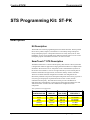
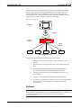
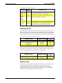
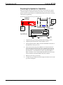
Crestron ST-PK Programming Kit Contents STS Programming Kit: ST-PK 1 Description.................................................................................................................................................1 Kit Description...........................................................................................................................1 SmarTouch™ STS Description ...............................................................................................1 Software......................................................................................................................................2 Leading Specifications .............................................................................................................3 Setup ...........................................................................................................................................................4 STS Equipment ..........................................................................................................................4 Applying Power.........................................................................................................................6 Identity Code .............................................................................................................................6 Preparing the System for Programming..................................................................................7 Preparing the System for Operation .......................................................................................8 Problem Solving.........................................................................................................................................9 Troubleshooting........................................................................................................................9 Further Inquiries......................................................................................................................11 Return and Warranty Policies ...............................................................................................................12 Merchandise Returns / Repair Service.................................................................................12 CRESTRON Limited Warranty ..............................................................................................12 Operations Guide - DOC. 5662C Contents • i Crestron ST-PK Programming Kit STS Programming Kit: ST-PK Description Kit Description The ST-PK is the Crestron programming kit for the SmarTouch STS. The kit provides the necessary cables, adapters, and software to successfully design and upload unique touchpanel projects. Components of the kit are clearly listed, refer to “STS Equipment” on page 4. The ST-PK can be used time and time again to revise current touchpanel projects of the SmarTouch STS or to create new ones. SmarTouch™ STS Description The SmarTouch STS is a Crestron radio-frequency (RF) wireless control system that is designed for numerous applications ranging from the boardroom to complete home automation. Electronic devices or subsystems can be controlled from anywhere via the wireless user interface. Users are no longer tethered by a wired control panel or limited to infrared line-of-sight control, as with most ordinary wireless controllers. There are six SmarTouch STS configurations available. All configurations are functionally identical except for the touchpanel component which can be grayscale or color, the type of input power required which can be 120V or 220V, and the communication frequency. The table shown below provides a breakdown of SmarTouch STS configurations. For the purpose of this Operations Guide, the term “SmarTouch STS” is used to describe a SmarTouch configuration and its components. Table of SmarTouch Configurations Operations Guide - DOC. 5662C SMARTOUCH STS CONFIGURATION DISPLAY STS STS-C STSI STSI-C STSI/UK STSI-C/UK Grayscale Color Grayscale Color Grayscale Color POWER (VOLTAGE) 120V 120V 220V 220V 220V 220V AC AC AC AC AC AC TRANSMISSION FREQUENCY 433.92 MHz 433.92 MHz 433.92 MHz 433.92 MHz 418 MHz 418 MHz STS Programming Kit: ST-PK • 1 Programming Kit Crestron ST-PK This RF system is primarily comprised of two units, a touchpanel and the control processor. Refer to the system diagram shown below. The touchpanel is a LCD interface that communicates via RF signals to the control processor, which is discretely placed. The control processor interfaces with the controllable electronic equipment in the system to complete commands without delay. SmarTouch STS Diagram TOUCHPANEL RF SIGNALS CONTROL PROCESSOR IR/RS-232 INTERFACE CONTROLLED DEVICES Features of the SmarTouch STS wireless control system include: • high-clarity LCD touchpanel displays choice of custom icons and graphics. • touchpanel case is lightweight and contoured and easily held in one hand. • advanced Crestron RF technology allows complete freedom of movement -up to 500 feet through walls, indoors or outside. • touchpanel power options include rechargeable power pack or AC power supply. • control processor includes Cresnet network port for expansion. • exclusive Crestron/Windows software gives you system programming options (use the included templates or create fully customized environments). Software NOTE: Use the provided software, VisionTools™ Pro to design user interface pages for the SmarTouch STS. The latest revision of the Crestron Database is available from the Software Downloads page (Cresdb Library) of the Crestron website (www.crestron.com). 2 • STS Programming Kit: ST-PK Operations Guide - DOC. 5662C Crestron ST-PK Programming Kit VisionTools™ Pro (VT Pro) is a Crestron design and programming Windows-based software for the SmarTouch STS. Unlimited control screen variations incorporating two and three-dimensional graphics and text are possible with VT Pro. A set of pages which make up a project can be designed for each STS application. Each touchpanel can be organized with the ideal, color-oriented control environment with custom control graphics: icons, two and three-dimensional buttons, and floor plans. The project is uploaded to the touchpanel and programmed into the flash PROM. The touchpanel uses the programmed project until another is uploaded from the PC. The PC may be disconnected from the control processor except during reprogramming. Use Crestron’s STS Wizard to reduce to project development phase to just nine steps. This “drag-n-drop” Windows software assures thorough system configuration. For a simple system, set up takes just a few minutes. Touchpanel templates may be modified for a more custom system. For additional software information, refer to the help file provided with the software. A SmarTouch tutorial is provided as a guide for the novice programmer. Lotus ScreenCam movies for the Wizard are also available from the latest version of the Crestron ControlCD. Let these movies demonstrate the simplicity of STS Wizard. Learn how to use and get the most from Crestron software. Leading Specifications The table below provides a summary of leading specifications for the SmarTouch STS and its primary components. Dimensions and weight are rounded to the nearest hundredth unit. Leading Specifications of the SmarTouch STS SPECIFICATION DETAILS Touchpanel Power Options ST-BTP : Rechargeable NiCad power pack (Fully charged battery, 2800 mAh capacity, can last up to 10 days depending on touchpanel settings and usage.) AC (domestic) : 12V DC, 1.0A, 120V Input (P/N PW-1210 or equivalent) AC (internat'l) : 12V DC, 1.0A, 230V Input (P/N PWI-1210 or equivalent) ST-DS : Docking Station provides power as long as it is receiving power from its external AC power pack. Control Processor Power Options AC (domestic): 12V DC, 0.5A, 120V Input (P/N PW-1205 or equivalent) AC (internat'l) : 12V DC, 1.0A, 230V Input (P/N PWI-1210 or equivalent) VisionTools™ Pro Version 1.1.3 or later Crestron Database Version 11.7.211 or later Touchpanel Dimensions & Weight Height: 5.70 in (14.48 cm) (without rechargeable power pack and Width: 8.75 in (22.23 cm) AC power pack) Depth: 3.33 in (8.45 cm) Weight: 1.85 lb (0.84 kg) Control Processor Dimensions & Height: 1.70 in (4.32 cm) Weight (without AC power pack) Width: 7.07 in (17.95 cm) Depth: 6.32 in (16.06 cm) Weight: 1.90 lb (0.86 kg) Operations Guide - DOC. 5662C STS Programming Kit: ST-PK • 3 Programming Kit Crestron ST-PK As of the date of manufacture, the unit has been tested and found to comply with specifications for CE marking. NOTE: Equipment has been tested and found to comply with the limits for a Class B digital device, pursuant to part 15 of the FCC Rules. These limits are designed to provide reasonable protection against harmful interference in a residential installation. The equipment generates, uses and can radiate radio frequency energy and, if not installed and used in accordance with the instructions, may cause harmful interference to radio communications. However, there is no guarantee that interference will not occur in a particular installation. If this equipment does cause harmful interference to radio or television reception, which can be determined by turning the equipment off and on, the user is encouraged to try to correct the interference by one or more of the following measures: n Reorient or relocate the receiving antenna. n Increase the separation between the equipment and receiver. n Connect the equipment into an outlet on a circuit different from that to which the receiver is connected. n Consult the dealer or an experienced radio/TV technician for help. Setup STS Equipment The items required to program STS equipment, listed below, are provided as part of the programming kit (ST-PK). These kit items can be used time and time again to program or reprogram each system. STS Kit Equipment EQUIPMENT PART NUMBER DESCRIPTION Software SAXD2535-1AY1 Software package for creating touch screen programs. Programming 15710 Provides connection between touchpanel and Cable Assembly control processor. Used during programming only. RJ11 Cable 15717 Provides connection between control processor Assembly and RJ11/DB9F adapter. Used during programming only. RJ11 to DB9F 15556-1B Provides connection between RJ11 cable Adapter assembly and a PC. Used during programming only. 4 • STS Programming Kit: ST-PK Operations Guide - DOC. 5662C Crestron ST-PK Programming Kit Due to variations in installation requirements and overall application, not all possible peripheral pieces of equipment are supplied with the STS system. The next table in this section, shown below, provides a list of all equipment that is provided with the STS system. Except for the STIRP, all products listed in the part number column ship one item per system. STS System EQUIPMENT Touchpanel Control Processor Rechargeable Power Pack Docking Station Infrared Probe External AC Power Pack PART NUMBER ST-1550 ST-1550C ST-1550/UK ST-1550C/UK ST-CP ST-CP/UK ST-BTP SHIPPED WITH DESCRIPTION STS or STSI STS-C or STSI-C STSI/UK STSI-C/UK STS, STS-C, STSI, or STSI-C STSI/UK or STSI-C/UK All Systems Provides user interface. Provides commands to system A/V equipment. Possible power source for touchpanel. ST-DS All Systems Provides fast or trickle charge to ST-BTP. STIRP All Systems Delivers commands (2 per System) from control processor. PW-1205 STS or STS-C Provides power to PWI-1210 STSI, STSI-C, STSI/UK or touchpanel and control STSI-C/UK processor. PW-1215 STS or STS-C Provides power PWI-1215 STSI, STSI-C, STSI/UK or to ST-DS. STSI-C/UK The next table in this section, shown below and on the next page, lists some peripheral equipment that can be purchased separately for the STS system. The part number for each item (except for the ST-RMK) is supplied with the appropriate domestic or international external AC power pack. Keep in mind that all the individual items of the system (listed in the STS System table, above) can be purchased separately as well. STS Peripheral Equipment EQUIPMENT Rack Mount Input/Output Expansion Module Volume Control Module Current Sensor Operations Guide - DOC. 5662C PART NUMBER DESCRIPTION ST-RMK Provides rack space for STS units. ST-IO Provides isolated relays/digital input. ST-VC ST-CS Provides volume controls - 3 independent, professional quality VOLUME/TONE control, balanced or unbalanced I/O. Provides dual capacity for measuring the average current of each half cycle of an AC load. STS Programming Kit: ST-PK • 5 Programming Kit Crestron ST-PK STS Peripheral Equipment (Continued) EQUIPMENT RS-232/422 COM Module Lutron Interface Power Control Module Video Sensor IR/Serial Learner PART NUMBER DESCRIPTION ST-COM Provides two independent bidirectional serial ports that support RS-232/422-based communication. ST-LT Provides a direct interface to Lutron's GRAFIK EYE. ST-PC Provides two switchable AC outlets. ST-VS Detects the presence of a video signal coming out of the baseband video port for up to four independent sources. CNXLIR Creates driver files that can be added to the User Database of the SmarTouch software package. Applying Power The touchpanel can be powered via an external AC power pack, while resting in the ST-DS, or via the ST-BTP. Each of these supplied items have their own Operations Guides which details proper usage. Refer to the table below for the required document number. This table does not account for the latest revision letter of each document. Devices that Power the SmarTouch STS Touchpanel POWER OPTION NOMENCLATURE DOCUMENT NUMBER Domestic External AC Power Pack International External AC Power Pack Docking Station Battery Pack PW-1210 PWI-1210 ST-DS ST-BTP 5762 5763 5738 5746 The control processor can only be powered via the appropriate external AC power pack. Refer to the table below for power pack’s document number. Again, the table does not account for the latest revision letter of each document. SmarTouch STS Control Processor External AC Power Packs POWER OPTION NOMENCLATURE DOCUMENT NUMBER Domestic External AC Power Pack International External AC Power Pack PW-1205 PWI-1210 5759 5763 Identity Code All Crestron expansion modules and touchpanels within the Cresnet system require a unique identity code (NET ID). These codes are recognized by a two-digit hexadecimal number from 03 to FE. Matching NET IDs between the expansion modules and touchpanels with the program is required if data is to be successfully transferred or new touchpanel screens are to be loaded. 6 • STS Programming Kit: ST-PK Operations Guide - DOC. 5662C Crestron ST-PK Programming Kit Preparing the System for Programming When programming, refer to figure shown below for typical connection diagram for the SmarTouch STS. Complete the following steps in the order provided to ensure proper connection of the system. Typical Connection Diagram when Programming the SmarTouch STS Touchpanel TOUCHPANEL NOTE: UNITS IN THIS ILLUSTRATION ARE NOT DRAWN TO SCALE. AC POWER PACK (CRESTRON MODEL OR EQUIVALENT) AC POWER PACK (CRESTRON MODEL OR EQUIVALENT) PROGRAMMING CABLE ASSEMBLY (15710) PC RJ11 CABLE ASSEMBLY (15717) SERIAL PORT CONTROL SYSTEM USE ADAPTER (15556-1B) NOTE: The PC to control processor and touchpanel to control processor cables only need to be attached when programming. Operations Guide - DOC. 5662C 1. Using the RJ11 cable assembly (15717) and RJ11 to DB9F adapter (15556-1B) connect the SmarTouch control processor to the RS-232 port on the PC. 2. Using the programming cable assembly (15710) connect the touchpanel to the SmarTouch control processor port, labeled NET. 3. Attach the appropriate external AC power pack to the SmarTouch control processor and insert plug into outlet. 4. Apply power to the touchpanel. Consult the appropriate document listed in “Applying Power” on page 6. - If the external AC power pack is used, attach it to the touchpanel and plug into outlet. - If the ST-DS is used, rest touchpanel in station and plug into outlet. - If the ST-BTP is used, insert battery pack into battery compartment. STS Programming Kit: ST-PK • 7 Programming Kit Crestron ST-PK Preparing the System for Operation When operating the SmarTouch STS refer to the figure shown below for a typical connection diagram. Complete the following steps in the order provided to ensure proper connection of the system. It is assumed that the SmarTouch STS is currently connected for programming. Typical Connection Diagram During Normal Operation CONTROL SYSTEM AC POWER PACK (CRESTRON MODEL OR EQUIVALENT) ATTACH ANTENNA AC POWER PACK (CRESTRON MODEL OR EQUIVALENT) TOUCHPANEL NOTE: UNITS IN THIS ILLUSTRATION ARE NOT DRAWN TO SCALE. STIRP 8 • STS Programming Kit: ST-PK SENSOR VCR 1. Completely disconnect the programming cable assembly (15710). 2. Completely disconnect the RJ11 cable assembly (15717). 3. Attach supplied antenna to BNC connector labeled RF on the back of the SmarTouch control processor. 4. Insert the mono mini plug of the STIRP into one of the four IR OUT ports of the SmarTouch control processor. Identifying the correct IR OUT port depends on the designations made when programming. In this illustration, it is assumed that the VCR is assigned to PORT A. Refer to the latest revision of the STIRP Installation Instructions (Doc. 5674) for details to attach the STIRP to IR sensor windows. 5. Repeat previous step, as necessary. 6. To begin using your SmarTouch STS, simply touch the screen to wake up your the touchpanel. Operations Guide - DOC. 5662C Crestron ST-PK Programming Kit Problem Solving Troubleshooting The table below and on the next page provides corrective action for possible trouble situations. If further assistance is required, please contact a Crestron technical support representative. SmarTouch STS Troubleshooting TROUBLE Project can not be uploaded to the touchpanel. Wrong screens appear on touchpanel. System does not function (LEDs on STCP do not illuminate). Touchpanel display is dark. Touchpanel display is dark or too light. Unexpected response from touchpanel. Touchpanel exhibits slow operation. Operations Guide - DOC. 5662C POSSIBLE CAUSE(S) CORRECTIVE ACTION NET ID on touchpanel Verify that NET ID match. Refer to is improperly set. "Configuring the Touchpanel" in the latest revision of the SmarTouch STS Touchpanels Operations Guide (Doc. 5803). Touchpanel has Touch screen to wake it up. NOTE: It may be powered down. necessary to increase POWER DOWN TIMEOUTS during development sessions. Refer to "Configuring the Touchpanel" in the latest revision of the User's Operations Guide (Doc. 5804). Verify that power is properly applied. Refer to "Applying Power" in this Operations Guide. Screens were not Down load screens as described in the help uploaded. files found in VT Pro. No system power. Touchpanel is incorrectly calibrated. Backlight timeout has elapsed. Power is not applied to the touchpanel. Screen brightness or contrast is improperly set. Touchpanel is incorrectly calibrated. Compressed graphics take time to decompress. Confirm power is supplied to the system. Calibrate the touchpanel. Refer to "Configuring the Touchpanel" in the latest revision of the User's Operations Guide (Doc. 5804). Touch screen to reactivate. Verify that power is properly applied. Refer to "Applying Power" in this Operations Guide. Hold finger to the touchscreen for more than 10 seconds as power is applied. The display sets the brightness and contrast to a safe value. Calibrate the touchpanel. Refer to "Configuring the Touchpanel" in the latest revision of the User's Operations Guide (Doc. 5804). If there are no memory problems, decompressed graphics decrease the drawing time of panel pages. STS Programming Kit: ST-PK • 9 Programming Kit Crestron ST-PK SmarTouch STS Troubleshooting (Continued) TROUBLE POSSIBLE CAUSE(S) CORRECTIVE ACTION RF LED on ST-CP illuminates, but COM or IR LEDs do not illuminate. Touchpanel RF ID is not set to match the RF ID assigned in the SmarTouch system program. RF LED on ST-CP does not illuminate when trying to control A/V equipment. Button on screen only Reopen project and verify that button join has internal functions number is between 1 and 999. NOTE: Can (i.e., join number not assign join numbers to a border. equals 'NONE" or is greater than or equal to 1000. A/V device does not respond. Verify that RF ID match. Refer to "Configuring the Touchpanel" in the latest revision of the SmarTouch STS Touchpanels Operations Guide (Doc. 5803). ST-CP is not receiving Verify that the proper external AC power pack power. is attached to ST-CP. RF antenna is not Verify that ST-CP RF antenna is properly securely attached to ST-attached. CP RF port. RF antenna is not Remotely locate RF antenna. Mount the properly located (i.e., antenna outside of the rack by using a inside a metal rack). bulkhead type BNC barrel and a BNC to BNC 50 ohm cable. RF transmitter in Contact a Crestron technical support SmarTouch is faulty. representative. STIRP or serial port not Verify placement of STIRP (Hold phosphor placed properly. card under STIRP while pressing button) and tightness of serial cable. Used wrong IR or serial Verify proper IR or serial port is defined. port. Wrong manufacturer or Open the project in software and verify model number listed in device definition. SmarTouch system. Incorrect program is in Verify program is uploaded to control system control system. with Performance Viewport from the software. Incorrect panel screens Use the software to open the project and are in touchpanel. verify that each button that is suppose to control the device has a join number and the command associated with it lists "SEND<device name> <function name>" (e.g., SEND LIV_RM_VCR PLAY). Download the touchpanel screens again. A/V device SmarTouch system Open SmarTouch system via software and does not calls out wrong port or change the port. respond and no port for device. wrong LEDs on ST-CP for device’s IR or serial port illuminate. 10 • STS Programming Kit: ST-PK Operations Guide - DOC. 5662C Crestron ST-PK Programming Kit Further Inquiries If after reviewing this Operations Guide, you can not locate specific information, please take advantage of Crestron's award winning technical support team in your area. Dial one of the following numbers. • In the US and Canada, call Crestron’s corporate headquarters at 1-888-CRESTRON [1-888-273-7876] or 1-201-767-3400. • In Europe, call Crestron International at +32-15-50-99-50. • In Asia, call Crestron Asia at +852-2341-2016. • In Latin America, call Crestron Latin America at +525-574-15-90. For local support from exclusive Crestron factory-trained personnel call: Operations Guide - DOC. 5662C • In Australia, call Soundcorp at +613-941-61066. • In New Zealand, call Amber Technologies at +649-410-8382. STS Programming Kit: ST-PK • 11 Programming Kit Crestron ST-PK Return and Warranty Policies Merchandise Returns / Repair Service 1. No merchandise may be returned for credit, exchange, or service without prior authorization from CRESTRON. To obtain warranty service for CRESTRON products, contact the factory and request an RMA (Return Merchandise Authorization) number. Enclose a note specifying the nature of the problem, name and phone number of contact person, RMA number, and return address. 2. Products may be returned for credit, exchange, or service with a CRESTRON Return Merchandise Authorization (RMA) number. Authorized returns must be shipped freight prepaid to CRESTRON, Cresskill, N.J., or its authorized subsidiaries, with RMA number clearly marked on the outside of all cartons. Shipments arriving freight collect or without an RMA number shall be subject to refusal. CRESTRON reserves the right in its sole and absolute discretion to charge a 15% restocking fee, plus shipping costs, on any products returned with an RMA. 3. Return freight charges following repair of items under warranty shall be paid by CRESTRON, shipping by standard ground carrier. In the event repairs are found to be non-warranty, return freight costs shall be paid by the purchaser. CRESTRON Limited Warranty CRESTRON ELECTRONICS, Inc. warrants its Cresnet products, denoted by a "CN" prefix model number, to be free from manufacturing defects in materials and workmanship for a period of three (3) years from the date of shipment to purchaser. Disk drives and any other moving or rotating mechanical parts are covered for a period of one (1) year. CRESTRON warrants all its other products for a period of one year from the defects mentioned above, excluding touchscreen display components which are covered for 90 days. Incandescent lamps are completely excluded from Crestron's Limited Warranty. CRESTRON shall, at its option, repair or replace any product found defective without charge for parts or labor. Repaired or replaced equipment and parts supplied under this warranty shall be covered only by the unexpired portion of the warranty. CRESTRON shall not be liable to honor warranty terms if the product has been used in any application other than that for which it was intended, or if it has been subjected to misuse, accidental damage, modification, or improper installation procedures. Furthermore, this warranty does not cover any product that has had the serial number altered, defaced, or removed. This warranty shall be the sole and exclusive remedy to the purchaser. In no event shall CRESTRON be liable for incidental or consequential damages of any kind (property or economic damages inclusive) arising from the sale or use of this equipment. CRESTRON makes no other warranties nor authorizes any other party to offer any warranty, expressed or implied, including warranties of merchantability for this product. This warranty statement supersedes all previous warranties. Trademark Information All brand names, products names, and trademarks are the sole property of their respective owners. Windows is a registered trademark of Microsoft Corporation. Windows95, Windows98 and WindowsNT are trademarks of Microsoft Corporation. 12 • STS Programming Kit: ST-PK Operations Guide - DOC. 5662C