1
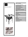
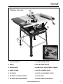
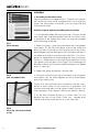
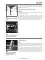
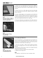
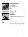
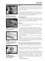
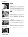
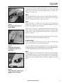
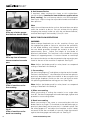
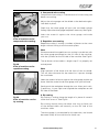
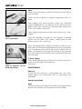
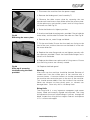
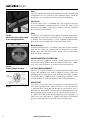
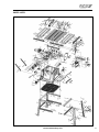
®
255mm TCT Multipurpose Table Saw
Original
Instructions
Read instructions before operating this tool.
www.evolutionfury.com
TABLE OF CONTENTS
GB
Instruction Manual
Read instructions before operating this tool.
EC - Declaration of Conformity
04
Important Information
05
12 Month Limited Warranty
05
General Safety Rules
05
Safety Precautions for Table Saws
07
Symbols08
Additional Specific Safety Rules
08
Specification09
Machine Overview
11
Assembly12
Operation18
Maintenance22
Environmental Protection
24
Service Parts Lists
25
2
EC - DECLARATION OF CONFORMITY
We, manufacturer and importer
Evolution Power Tools Ltd.
Venture One
Sheffield
S20 3FR
Declare that the product
Part numbers:
FURY 52551, FURY 52552, FURY 52552EU
Evolution: FURY TABLE SAW – 255mm
Complies with the essential requirements
of the following European Directives:
2006/42/EC – Machine Directive
2006/95/EC – Low Voltage Directive
2004/108/EC – EMC Directive
2002/95/EC – Restriction of the use of Certain
Hazardous Substances in Electrical and
Electric equipment.
The following standards
have been applied:
EN 61029-1:2009
EN 61029-2-1:2010
EN 55014-1:2006
EN 55014-2:1997+A1
EN 61000-3-2:2006
EN 61000-3-3:1995+A1+A2
Authorised by
Mr Matthew J Gavins
Managing Director
1st June 2010
All documentation is held on file at the
above address and is available, on request
for review.
3
www.evolutionfury.com
IMPORTANT
Please read these operating and safety
instructions carefully and completely. For
your own safety, before using this equipment
check that the voltage is correct and that all
handles and parts are firmly secured. If you
are uncertain about any aspect of using this
equipment, please contact our Technical
helpline.
Helpline.
Technical Helpline UK Technical Helpline USA 0870 609 2297
1-866-EVO-TOOL
EVOLUTION 255mm FURY 5 TABLE SAW
Congratulations on your purchase of an
Evolution Power Tool 10˝ Fury Table Saw.
Please complete your product registration
on line to validate your machine’s warranty
period and ensure prompt service if needed.
We sincerely thank you for selecting a
product from Evolution Power Tools.
12 MONTH LIMITED WARRANTY
Evolution Power Tools reserves the right to
make improvements and modifications to
design without prior notice.
Evolution Power Tools will, within twelve (12)
months from the original date of purchase,
repair or replace any goods found to be
defective in materials or workmanship. This
warranty is void if the tool being returned
has been used to cut materials beyond
the recommendations in the Instruction
Manual or if the saw has been damaged by
accident, neglect, or improper service. This
warranty does not apply to machines and
/ or components which have been altered,
changed, or modified in any way, or subjected
to use beyond recommended capacities
and specifications. Electrical components
are subject to respective manufacturers’
warranties. All goods returned defective
shall be returned prepaid freight to Evolution
Power Tools. Evolution Power Tools reserves
the right to optionally repair or replace it with
the same or equivalent item. There is no
warranty – written or verbal – for saw blades.
In no event shall Evolution Power Tools be
liable for loss or damage resulting directly or
indirectly from the use of our merchandise or
from any other cause. Evolution Power Tools
is not liable for any costs incurred on such
goods or consequential damages. No officer,
employee or agent of Evolution Power Tools
is authorised to make oral representations of
fitness or to waive any of the foregoing terms
of sale and none shall be binding on Evolution
Power Tools. Questions relating to this
limited warranty should be directed to the
company’s head office, or call the appropriate
Helpline number.
IMPORTANT SAFETY INSTRUCTIONS
To reduce the risk of electric shock, this
equipment is fitted with an approved cord
and plug for its intended country of use. Do
not change the cord or plug in any way.
GENERAL SAFETY INSTRUCTIONS
WARNING! When using electric tools basic
safety precautions should always be followed
to reduce the risk of fire, electric shock and
personal injury including the following. Read
all these instructions before attempting
to operate this product and save these
instructions.
1 - Keep work area clear
- Cluttered areas and benches invite injuries.
2 - Consider work area environment
- Do not expose tools to rain.
- Do not use tools in damp or wet locations.
- Keep work area well lit.
- Do not use tools in the presence of
flammable liquids or gases.
3 - Guard against electric shock
- Avoid body contact with earthed or
grounded surfaces (e.g. pipes, radiators,
ranges, refrigerators).
4 - Keep other persons away
- Do not let persons, especially children, not
involved in the work touch the tool or the
extension cord and keep them away from the
work area.
5 - Store idle tools
- When not in use, tools should be stored in a
dry locked-up place, out of reach of children.
6 - Do not force the tool
- It will do the job better and safer at the rate
for which it was intended.
www.evolutionfury.com
4
7 - Use the right tool
- Do not force small tools to do the job of a
heavy duty tool.
- Do not use tools for purposes not intended;
for example do not use circular saws to cut
tree limbs or logs.
8 - Dress properly
- Do not wear loose clothing or jewellery, they
can be caught in moving parts.
- Non-skid footwear is recommended when
working outdoors.
- Wear protective hair covering to contain
long hair.
9 - Use protective equipment
- Use safety glasses.
- Use face or dust mask if working operations
create dust.
10 - Connect dust extraction equipment
- If the tool is provided for the connection of
dust extraction and collecting equipment,
ensure these are connected and properly used.
11 - Do not abuse the cord
- Never yank the cord to disconnect it from
the socket. Keep the cord away from heat, oil
and sharp edges.
12 - Secure work
- Where possible use clamps or a vice to hold
the work. It is safer than using your hand.
13 - Do not overreach
- Keep proper footing and balance at all times.
14 - Maintain tools with care
- Keep cutting tools sharp and clean for better
and safer performance.
- Follow instruction for lubricating and
changing accessories.
- Inspect tool cords periodically and if damaged
have them repaired by an authorized service facility.
- Inspect extension cords periodically and
replace if damaged.
- Keep handles dry, clean and free from oil
and grease.
15 - Disconnect tools
- When not in use, before servicing and when
changing accessories such as blades, bits and
cutters, disconnect tools from the power supply.
16 - Remove adjusting keys and wrenches
- Form the habit of checking to see that keys
and adjusting wrenches are removed from
the tool before turning it on.
5
17 - Avoid unintentional starting
- Ensure switch is in “off” position when
plugging in.
18 - Use outdoor extension leads
- When the tool is used outdoors, use only
extension cords intended for outdoor use and
so marked.
19 - Stay alert
- Watch what you are doing, use common
sense and do not operate the tool when you
are tired.
20 - Check damaged parts
- Before further use of tool, it should be
carefully checked to determine that it will
operate properly and perform its intended
function.
- Check for alignment of moving parts, binding of
moving parts, breakage of parts, mounting and
any other conditions that may affect its operation.
- A guard or other part that is damaged
should be properly repaired or replaced by an
authorized service centre unless otherwise
indicated in this instruction manual.
- Have defective switches replaced by an
authorized service centre.
- Do not use the tool if the switch does not
turn it on and off.
21 - Warning
- The use of any accessory or attachment
other than one recommended in this
instruction manual may present a risk of
personal injury.
22 - Have your tool repaired
by a qualified person
- This electric tool complies with the relevant
safety rules. Repairs should only be carried
out by qualified persons using original
spare parts, otherwise this may result in
considerable danger to the user.
www.evolutionfury.com
HEALTH ADVICE
Warning!
When drilling, sanding, sawing or grinding,
dust particles will be produced. In some
instances, depending on the materials you
are working with, this dust can be particularly
harmful to you (e.g. lead from old gloss
paint).You are advised to consider the risks
associated with the materials you are working
with and to reduce the risk of exposure.
You should:
- Work in a well-ventilated area.
- Work with approved safety equipment, such
as dust masks that are specially designed to
filter microscopic particles.
SAFETY PRECAUTIONS
FOR TABLE SAWS
a) Do not use saw blades which are
damaged or deformed.
b) Replace the table insert/access plate if worn.
c) Use only blades as recommended in
this manual, which conform to EN 847-1.
When changing the saw blade beware that
the width of the groove cut of the saw blades
shall not be less than and the thickness of
the body of the saw blade shall not be more
than the thickness of the riving knife.
d) Take care that the selection of the saw blade
is suitable for the material to be cut.
e) Wear suitable personal protective equipment
when necessary. This could include:
• Hearing protection to reduce the risk of
induced hearing loss.
• Respiratory protection to reduce the risk of
inhalation of harmful dust.
• Wear gloves when handling saw blades and
rough material. Saw blades shall be carried in
a holder whenever practicable.
f) Never perform any operation freehand.
This means using only your hands to support
or guide the workpiece. Always use either
the fence or mitre gauge to position and
guide the work.
Warning: Freehand cutting is a major
cause of accidents.
g) Never attempt to free a stalled blade
without first turning the saw off. Turn the
power off immediately to prevent damage to
the motor.
h) Provide adequate support for long or
wide workpieces.
i) Avoid awkward operations and hand
positions where a slip could cause your
hand to move into the blade.
www.evolutionfury.com
6
SAFETY SYMBOLS
To obtain an additional copy of your manual,
please contact Evolution Power Tools at:
WARNING!
Do not operate the saw if any warning
and / or instruction labels are missing or
damaged. Contact evolution power tools for
replacement labels.
Symbol
Description
V
Volts
A
Amperes
Hz
Min
Speed
~
Alternating Current
No
No Load Speed
Wear Safety
Goggles
Wear Ear Protection
Do Not Touch
Wear Dust Protection
Restriction
of Hazardous
Substances Directive
CE certification
Waste electrical and
electronic equipment
Only use genuine Evolution replacement
blades. Unauthorized blades may be
dangerous! Keep the blades securely
fastened. Check for debris before installing
any new blades and do not use dull or
broken blades. Check the blades regularly for
condition and wear. Damaged or worn blades
should be replaced immediately. Loose
fitting or damaged guards must be replaced
immediately. Beware of ejecting chips as
they may be HOT. Always make provisions
for safe handling of excess material.
7
ADDITIONAL SPECIFIC
SAFETY RULES FOR TABLE SAWS
Warning
Before using your table saw it is important that
you read and understand these safety rules.
Failure to follow these rules could result in serious
injury to the operator or damage to the table saw.
Hertz
-1
UK 0870 609 2297
USA
1-866-EVO-TOOL
WEBwww.evolutionpowertools.com
a) Always use the blade guard. The blade
guard must always be used in every operation.
b) Hold the work firmly. Against the mitre
gauge or rip fence.
c) Always use push-sticks or push blocks
to feed the workpiece past the saw blade.
d) Keep guards in place and in working
order. Always ensure that the riving knife is
fitted and correctly adjusted. Inspect the riving
knife regularly and replace it if it is worn. Use
only a genuine Evolution riving knife as this is a
dedicated component for this machine.
e) Remove adjusting keys and wrenches.
Form the habit of checking to see that keys
and adjusting wrenches are removed from the
machine before turning it on.
f) Do not use in dangerous environment. Do
not use power tools in damp or wet locations,
or expose them to rain. Keep work area well
lit. Keep the area well ventilated.
g) Keep children away. All children and
visitors should be kept at a safe distance from
the work area.
h) Do not use High Speed Steel (HSS)
blades. Use only saw blades for which the
maximum possible speed is not less than the
maximum spindle speed of the tool and the
material to be cut.
i) The push stick or push block should
always be stored with the machine when
not in use.
www.evolutionfury.com
j) Connect the saw to a dust collection
device when sawing wood. The operator
should be informed of the factors that
influence exposure to dust e.g. type of
material being cut and the importance of local
extraction (capture or source) and the proper
adjustment hoods/baffles/chutes.
k) Use proper extension cord. Make sure
any extension cord is in good condition.
When using an extension cord, be sure to use
one heavy enough to carry the current your
machine will draw. An undersized cord will
cause a drop in line voltage resulting in loss
of power and possible overheating.
l) Always use safety glasses. Also use a
face or dust mask if the cutting operation is
dusty. Everyday eyeglasses only have impact
resistant lenses, they are NOT safety glasses.
m) Maintain tools with care. Keep
tools sharp and clean for best and safest
performance.
Follow
instructions
for
lubricating and changing accessories.
n) Disconnect from the power supply
before servicing, cleaning or and when
changing accessories, such as blades.
o) Use recommended accessories. Only
use genuine Evolution accessories.
p) Check for damaged parts. Before further
use of the tool, a guard or other part that is
damaged should be carefully checked to
determine that it will operate properly and
perform its intended function - check for
alignment of moving parts, binding of moving
parts, breakage of parts, mounting, and any
other conditions that may affect its operation.
A guard or other part that is damaged should
be properly repaired or replaced.
q) Keep hands out of the path of the saw
blade.
r) Never reach around the saw blade.
s) Turn off machine and wait for saw
blade to stop before making any fence
adjustments.
t) Never pull or carry the tool by the
power cord. Carrying or pulling the tool by
the power cord could cause damage to the
insulation or the wire connections resulting in
the possibility of electric shock or fire.
u) When transporting the machine use
a transportation device. Never use the
guards for handling or transportation.
v) During transportation the upper part of
the saw blade must be lowered fully and
covered by the guard.
w) All operators using this machine must
read the instructions and familiarize
themselves with the machines workings.
x) Never leave the saw running and
unattended. Do not leave the saw until the
saw has been switched OFF, and the blade
has come to a complete halt.
y) Rebating or grooving should not be carried
out unless suitable guarding, such as a
tunnel guard, is fitted above the saw table.
z) Saws shall not be used for slotting
(stopped groove).
SPECIFICATION FURY 255mm TABLE SAW
Voltage 230V ~50Hz
Input power
1500W
No load speed
2500min-1
Blade diameter ø10˝ (255mm) TCT
Blade bore
ø25.4mm
Blade kerf
2mm
Blade teeth
24T
Maximum depth of cut at 00
73mm
Maximum depth of cut at 45054mm
Net weight
25kg
Riving Knife Thickness
1.8mm
NOISE AND VIBRATION DATA
Sound pressure level:
93.0dB(A)
Sound power level:
104.3dB(A)
Uncertainty K
3 dB(A)
ACCESSORIES
Table Extensions:
2pcs
Extension Table Support Struts:
4pcs
Blade Changing Tool:
2pcs
Mitre Gauge:
1pc
Anti-bounce device:
1pc
Adjustable Rip Fence:
1pc
Rear Cantilever Braces:
2pcs
Push Stick:
1pc
Fence Rail:
2pc
Table Saw Stand (When Assembled):
1pc
Allen Key
1pc
Spanner1pc
Fence Locating Bar
1pc
www.evolutionfury.com
8
KNOW YOUR PARTS
9
1. Fixings grouped in sets
2. Stand components
3. Table extensions and struts etc
4. Other parts – mitre gauge, rip fence, top
guard, fence rail
www.evolutionfury.com
Machine Overview
4
9
3
5
2
7
8
6
13
1
14
11
10
12
1. ON/OFF SWITCH
8. SLIDING MITRE FENCE
2. BLADE
9. ANTI-BOUNCE DEVICE
3. RIVING KNIFE
10. RISE & FALL ADJUSTMENT HANDLE
4. BLADE GUARD
11. BEVEL LOCKING LEVER
5. RIP FENCE
12. BEVEL ADJUSTMENT WHEEL
6. RIP FENCE LOCKING HANDLE
13. PUSH STICK
7. RIP FENCE SCALE MAGNIFIER
14. REAR CANTILEVER BRACES
www.evolutionfury.com
10
ASSEMBLY
1. Assembly of the table stand
Eight cross-pieces are supplied (Fig 1). The black cross-pieces
are for the top of the stand, the green ones are for mid way
fixing. The cross-pieces are paired, with two long and two
short of each colour.
Identify all parts before proceeding with assembly.
Fig 1
Parts laid out.
1. Fit the flexible rubber feet to the four legs. The two turned
over metal tabs should be guided into the two 25mm slots
in the base of the rubber foot which can then be moulded
around the base of the leg.
2. Select two legs, a long top cross-piece and a long green
cross-piece. Fit the top cross-piece to each leg using one
6mm hex bolt, ensuring that the locating lug on the crosspiece engages into the rectangular slot in the top of the leg. Fit
the green cross-piece using four 6mm hex bolts. This crosspiece has sloped ends to accommodate the splay of the legs.
Ensure it is fitted correctly with slope facing upwards. Do not
fully tighten any of the bolts at this stage. This assemblage will
become a side of the stand and should resemble a flat topped
letter ‘A’. See Fig 2.
3. Repeat the above to produce a second side.
Fig 2
One assembled side.
4. Using the remaining two top cross-pieces and two green
cross-pieces, join the sides together to form the rectangular
base of the table stand.
Ensure that the mounting holes formed by the top crosspieces at each corner of the stand are in alignment. The
machine mounting bolts can be loosely fitted in place as an
aid to alignment. (Front ø6mm x 30mm, rear ø6mm x 55mm)
5. Fit the two cantilever braces to a narrow side. This will
become the rear of the stand. These will
provide extra
stability and safety when the saw is in use. See Fig 3.
Fig 3
Close up view brace fitted
to leg.
11
www.evolutionfury.com
When finally satisfied with the construction, tighten all nuts
and bolts securely, and remove the mounting bolts from the
corner holes. See Fig 4.
2. Attaching the main body to the stand
Warning
This machine is heavy, enlist competent help when fastening
this machine to its base.
Fig 4
Overall view of completed
stand.
The main body of the saw can now be attached to the stand
using the four bolts, washers and nuts provided. Ensure that
the saw is attached to the stand the correct way round. The
bolts fasten through the machines four corner mounting holes,
and through the four corner holes in the stand. See Fig 5
Fig 5
Saw on stand. Front and
rear mounting positions.
3. Table Extensions
Note
The pressed steel table extensions are not handed and can fit
on either side of the machine. However the single hole in the
end of the extensions should be to the front of the saw table.
Fig 6
Close up view of bracing
struts attached to one
extension table.
1. Attach the four bracing struts to the table extensions using
6mm hex bolts with a washer under the head of the bolt as well
as the nut. Position the front strut in the first slot. Position the
rear strut in the single slot to the rear of the extension. Tighten
both struts in the middle of their respective slots. See Fig 6.
www.evolutionfury.com
12
2. Captive nuts are incorporated into the RH and LH edges of
the table. Attach the table extensions (single hole to the front)
to the table top using the ø5mm socket headed screws and
washers.
3. Ensure that the saw table edge and extension table edge
are flush and level with each other. Tighten the ø5mm socket
screws. See Fig 7.
Fig 7
Close up view of top of
machine showing table to
extension table join.
4. Using a straight edge or similar placed across the table and
extension to ensure alignment, position each bracing strut to
its body mounting turret. Use the hex headed self tapping
screw to secure each bracing strut to its turret. The screw will
cut its own thread into the turret slot. See Fig 8.
5. Final micro adjustment and alignment of the table extensions
is possible by repositioning the relevant fixing screw in their slots.
Fig 8
Close up detail. Fixing
strut to turret.
4. Assembling the Rip fence
The rip fence guide has an adjustable aluminium faceplate. For
normal use this should be attached to the steel carrier of the
rip fence with the deep (60mm) side in the vertical position
and on the LH side of the carrier. See Fig 9.
Fig 9
Close up view of the
assembled Rip Fence.
1. Place the two ø6mm x 60mm dome headed coach-bolts
into the two through holes in the carrier, dome heads to the
LH side.
2. Put washers and the finger nuts (by only a couple of threads)
onto the RH side of the carrier.
3. Slide the aluminium faceplate onto the bolt heads.
4. Tighten the two finger nuts.
Note
The magnifier in the Rip Fence clamp should be visible.
13
www.evolutionfury.com
5. The Fence Rail
Fig 10
Close up of view of fence
rail slotted together.
Note
The Fence Rail is supplied in two pieces which slot together.
The metal locating bar should be inserted into the rectangular
voids of the two extrusions to bridge both parts of the fence
rail. The bar should be equally located in either side of the
fence rail. See Fig 10. The six ø6mm x 15mm domed headed
coach bolts should be slid into the channel at the back of the
Fence Rail.
1. Offer the Fence Rail up to the front of the machine.
2. Position the six bolts to align with the six holes (one in each
extension and four in the main aluminium table). See Fig 11
3. Attach the Fence Rail to the machine using washers and
ø6mm nuts. Hand tighten only.
Adjusting
Fig 11
View of fence rail being
attached to machine.
Fig 12
Close up detailed view
of the fence rail being
adjusted.
Warning
The machine must not be connected to its mains supply when
carrying out the following procedure.
The Fence Rail needs to be positioned correctly for its
scale to read accurately.
1. Locate the Rip Fence in the Fence Rail to the RH side of
the Blade.
2. Raise the saw blade (see Operation Controls 2)
3. Slide the Rip Fence along the Fence Rail until it rests against
the raised saw blade.
4. Look through the Rip Fence magnifier, and gently move the
Fence Rail to the right or left until the ‘0’ position on the scale
coincides with the datum line in the magnifier. See Fig 12.
5. Check, and when satisfied that calibration has been
achieved, tighten the six Fence Rail nuts securely.
6. Lower the Blade.
Note
The Rip Fence simply slots into the Fence Rail, and can be
locked into position anywhere along the rails length, and at
either side of the machine by pressing the locking lever down.
www.evolutionfury.com
14
6. Checking/Adjusting the Rip Fence
When the Fence Rail and Rip Fence have been attached to the
machine, the Rip Fence should be checked to ensure that it
lies parallel to the blade.
Fig 13
Close up view of Rip Fence.
1. Raise the blade to its full height.
2. Rest a straight-edge or similar against the blade.
3. Bring the Rip Fence up to the straight-edge and check for
parallelism.
4. If adjustment is needed, gain access to the two socket
headed screws through the two holes in the steel carrier. See
Fig 13.
5. Loosen these screws using the correct sized allen key, and
adjust the fence as required.
6. Tighten and re-check the Rip Fence when correct alignment
has been achieved.
7. Lower the blade.
7. Sliding Mitre Gauge
Note
The sliding mitre gauge fits in either of the inverted ‘T’ slots in
the machine table.
The adjustable aluminium faceplate is held in the plastic
protractor base of the mitre gauge by two ø6mm domed
headed screws and thumb nuts.
Fig 14
Close up view of mitre
gauge. Anti-bounce device
not fitted.
15
The anti-bounce device can be fitted into the socket
incorporated into the mitre gauge base. See Fig 14.
Turning the locking handle anti-clockwise allows the mitre
gauge angle to be adjusted. Use the protractor scale and
pointer and set the gauge to the desired angle. Tighten the
vertical handle when the required angle has been set.
www.evolutionfury.com
Note
It is recommended that the anti-bounce device is fitted only
when needed (e.g. when cutting thin sheet material or thin
walled metal tube etc). At other times store away off the
machine for future use.
Fig 15
Close up view but with
anti-bounce device fitted.
The pillar of the anti-bounce device fits into the socket in the
mitre gauge base, and is held in place by a set screw. See Fig 15.
To attach or remove the pillar the mitre gauge faceplate will have
to be removed to gain access to the set screw.
8. Top Blade Guard
The top blade guard must be fitted to the machines riving
knife. The ‘split’ line along the top of the guard indicates the
cutting line of the saw blade below. Graphics on the guard
further reinforce the cutting line of the sawblade.
Warning
The machine must be disconnected from the mains supply
when installing the blade guard.
Fig 16
Close up view of the top
guard being fitted.
Fig 17A
Saw blade in upright position
with side covers deployed and
touching table.
1. Raise the blade to its full height to fully reveal the riving knife.
2. The guards locating pin should be positioned through the
hole in the riving knife and the washer and wing nut fitted to
one side. The blade guard must move up and down easily and
smoothly, so do not over-tighten this wing nut. See Fig 16.
3. Check the operation of the blade guard. Ensure that it is
working efficiently and covers the blade entirely at the sides
as well as the crown.
4. Lower the blade a little and recheck that the blade guard
operation.
5. When satisfied that the blade guard works throughout the
blades height adjustment range, check that when the blade is
fully lowered, the blade guard and side covers are in contact
with the table top. See Fig 17A.
Note: Guard Setting for Bevel, Mitre & Compound Cuts
When bevel, mitre or compound cutting it may be necessary
to remove the left or both blade side covers. See Fig 17B.
Use a crosshead screwdriver to remove the side cover
attachment screws and their plate washers. Securely store
the side covers, screws and washers for future use.
Fig 17B
Saw blade tilted to
discernable angle. Side
covers removed.
The guard should be secured to the riving knife by tightening
the locating pin wingnut. The guard should be positioned so
that the workpiece just slides under it, with the maximum
number of teeth possible shielded by the guard. Return
the guard to the original configuration when bevel, mitre or
compound cutting is completed. Recheck the operation of the
blade guard.
www.evolutionfury.com
16
OPERATION
Controls
1. On/Off Safety Switch
Warning: Before turning on the switch make sure that the
blade guard is correctly installed and operating properly.
Fig 18
Close up view of opened
switch.
To start the machine, press the tabs on either side of the red
safety button and lift it and the switch cover plate upwards to
reveal the on and off buttons. Push the ‘ON’ button to start the
machine and the ‘OFF’ button to stop the machine. See Fig 18.
WARNING
Never start the machine until all safety checks and procedures
have been carried out.
2. Raising/Lowering the blade
Warning: Only make adjustments to the machine when the
machine is switched OFF and the blade is stationary.
Fig 19
Close up view of elevating
handle.
The raising and lowering handle is used to raise or lower
the blade. Turn clockwise to lower the blade and counterclockwise to raise the blade. See Fig 19.
3. Tilting the Blade
The blade can be tilted up to 450 to the left.
To tilt the blade loosen the tilt locking lever and turn the tilt
adjusting wheel until the desired angle is achieved.
Tighten the tilt locking lever before using the machine. See Fig
20 (A) and Fig 20 (B).
Fig 20 (A)
Close up view of tilt
locking lever.
4. Rip Fence Guide
The rip fence can be positioned either side of the blade and
is locked in position by using the locking lever. Push down to
lock, and pull up to unlock.
Note: The rip fence guide incorporates a magnifier to aid
reading the measurement scale found on the fence rail.
Fig 20 (B)
Close up view of the tilt
adjusting wheel.
17
www.evolutionfury.com
Forwards and backwards adjustment of the rip fence
is possible. Loosen the two finger nuts and slide the
aluminium extrusion to the desired position. Tighten the
finger nuts securely.
Note
We recommend that normally the rip fence be adjusted so
that the rear of the guide is level with the rear of the blade
where it emerges from the table. See Fig 21.
Fig 21
Close up view of the rip
fence guide.
Note
If the rip fence is used on the LH side of the blade the
aluminium extrusion will have to be repositioned to the RH
side of the steel box-section carrier.
Undo the two wing nuts and remove the aluminium extrusion
with its bolts in place. Reposition the extrusion on the RH side
of the steel carrier and re-attach the wing nuts. See Fig 22.
Adjust as above.
Remember to return to the original configuration when the rip
fence is in the normal (RH) operating position.
5. Mitre Gauge
The mitre gauge can be used on either side of the table and
runs in two inverted T slots in the table top.
Fig 22
Close up view of the
rip fence set up for LH
operation.
Turn the vertical handle counter-clockwise to unlock the mitre
gauge, and adjust to the required angle. Turn the handle clockwise
to lock the mitre gauge at the chosen angle. See Fig 23.
Note
The extruded aluminium face plate of the mitre gauge should
be adjusted so that it is close to, but does not foul the blade
guard. Adjust by loosening the two wing nuts and sliding the
faceplate to the required position. Securely tighten the wing
nuts.
Fig 23
Close up view of the mitre
gauge set to an angle.
www.evolutionfury.com
18
6. Anti-bounce Device
If required, when cutting thin sheet or thin walled boxsection material (maximum 3mm thickness applies when
Steel cutting), the anti-bounce device can be employed.
See Fig 24. Adjust using the adjustable handle and knob for
best position.
Fig 24
Close up of mitre gauge.
Anti-bounce device fitted.
Note
Adjust the anti-bounce device so that the head does not quite
touch the material to be cut. You can achieve this by gently
clamping the material to be cut with the anti-bounce device,
and then backing off the head by 1/4 to1/2 a turn.
BASIC TABLE SAW OPERATIONS
Fig 25
Close up view of vacuum
cleaner attached to outlet
port.
WARNING
Never attempt freehand cuts on this machine. Always use
the appropriate guide or fence to minimise the possibility
of the blade binding and kickback. We recommend that
the saw blade protrudes through the material to be cut by
approximately 3mm. Adjust the height of the blade as
previously described. This machine is not suitable for cutting
rebates or stopped grooves. A vacuum cleaner or workshop
dust extraction device can be connected to the extraction port
found at the rear of the machine if required. See Fig 25.
Note: Adjust the blade guard for mitre, bevel or compound
cutting as detailed in Assembly 8.
1. Crosscutting
Set the mitre gauge to 00 and tighten using the vertical handle.
Position in the desired ‘T’ slot and adjust the mitre face plate as
previously described. Index the material to be cut against the
mitre gauge faceplate. Switch on the saw and allow to reach
full operating speed before making your cut. See Fig 26.
Fig 26
View of machine set for
Crosscutting.
Note: Adjust the blade guard for mitre, bevel or compound
cutting as detailed in Assembly 8.
2. Mitre crosscutting
Mitre crosscutting is cutting the material at an angle other
than 900. Set the mitre gauge to the desired angle, tighten and
proceed as crosscutting above.
Fig 27
View of machine set for
bevel crosscutting.
19
3. Bevel crosscutting
Bevel crosscutting is the same as crosscutting but with the
blade tilted at an angle. Tilt the blade to the desired angle as
previously described, and ensure that it is locked in place. Set
the mitre gauge to 00 and adjust the faceplate so that it does
not touch or foul the saw blade as it passes. Index the material
against the mitre gauge and make your cut. See Fig 27.
www.evolutionfury.com
4. Compound mitre cutting
Compound mitre cutting is a combination of mitre cutting and
bevel crosscutting.
Adjust the mitre gauge and the blade to the desired angles.
Lock both in place.
Check that the mitre gauge will pass the saw blade without
fouling. Adjust the mitre gauge faceplate if necessary. See Fig 28.
Fig 28
View of machine set for
compound mitre cutting.
Index the material against the mitre gauge and make
your cut.
5. Repetitive crosscutting
Repetitive cutting is cutting a number of pieces to the same
length without having to mark out each piece.
Note
We recommend that repetitive cross-cutting is carried out with
the mitre gauge positioned on the LH side of the machine,
with the rip fence on the RH side of the machine. See Fig 29.
Fig 29
View of machine set for
repetitive cutting.
The rip fence can be used as a length stop if it is properly set
and adjusted.
Note
Align the back of the fence with the front of the saw blade.
This will allow clearance for the material as it passes through
the saw blade.
Index the material to be cut against the mitre gauge and the rip
fence. Hold the material and mitre gauge with your left hand.
Gently push the workpiece through the saw. Use a push stick,
if necessary, in your right hand to guide the workpiece on the
RH side of the blade.
Fig 30
View of machine set for
rip cutting.
6. Rip cutting
Rip cutting is cutting along the length of a piece of material
rather than across it. See Fig 30.
Rip cutting should always be done with the rip fence set
to the desired width and normally on the RH side of the
machines table.
The mitre gauge is not required for this operation, and should
be stored safely off the machine for future use.
www.evolutionfury.com
20
Note
Check that the rip fence is locked in position and is parallel to
the saw blade.
Check that the riving knife is properly aligned with the saw
blade.
When ripping small section material a push stick should be
used to feed/guide the final 300mm of the material past the
blade. A push stick should always be used when making cuts
of less than 300mm. See Fig 31.
When ripping long boards or large panels always use a work
support.
Fig 31
Use of pushstick.
Feed the workpiece through the saw keeping it indexed
against the rip fence. Use smooth, steady pressure and
employ a push stick if necessary.
When the ripping width is greater than 300mm, and with care,
both hands can be used to guide/feed the material through the
saw. The operators left hand will be to the LH side of the saw
blade. The operators right hand will be close to the rip fence
on the RH side of the sawblade. Hands should never be in line
with the blade.
Fig 32
View of machine set for
bevel rip cutting.
7. Bevel ripping
When bevel ripping material 150mm or narrower use the rip
fence on the RH side of the blade only.
See Fig 32.
MAINTENANCE
Warning
Ensure that the machine is disconnected from the mains
supply before any maintenance tasks or adjustments are
attempted.
Changing the Blade
Note
We recommend that the operator considers wearing protective
gloves when handling or changing the machines blade.
21
www.evolutionfury.com
1. Disconnect the machine from the power supply
2. Remove the blade guard. (see Assembly 7)
3. Remove the table access plate by removing the two
countersunk head screws from either end of the access plate.
Lift the plate away and carefully store it and its fixing screws
for future use. See Fig 33.
4. Raise the blade to its highest position.
Fig 33
Removing the access plate.
5. Use the two blade changing tools provided. One to hold the
motor arbor, and the other to loosen the arbor nut. See Fig 34.
6. Remove the nut, outer flange and blade.
7. Fit the new blade. Ensure that the teeth are facing to the
front of the saw, and that the arrow on the blade is in line with
the motor direction.
8. Replace the outer flange and nut and tighten securely with
the spanners provided. Check that both blade flanges are in
contact with the blade.
9. Replace the table access plate and its fixing screws. Ensure
that the fixing screws are correctly seated.
Fig 34
Close up of removing
the blade using the tools
provided.
10. Replace the blade guard.
Cleaning
After each use the machine should be cleaned. Remove all
sawdust etc from the visible parts of the machine with a
vacuum cleaner. A vacuum cleaner can also be connected to
the machine dust extraction port at the rear of the machine.
This should remove debris from the inside of the machine.
Never use solvents to clean plastic parts, as solvents can
damage them. Clean only with a soft damp cloth.
Riving Knife
The riving knife is a very important component and comes
factory fitted and correctly aligned and adjusted. The riving
knife prevents the work from binding as it passes through the
blade. Inspect the riving knife at regular intervals and replace
it if it is worn or damaged.
www.evolutionfury.com
22
Note
Use only a genuine Evolution Riving Knife, as this is a dedicated
component for this machine. Non genuine parts could be
dangerous. If in any doubt, please contact the Helpline.
Push Stick
A plastic push stick is provided with the machine and has
its own dedicated storage brackets to the RH side of the
machines main body. See Fig 35. When not in use store the
push stick on the machine.
Fig 35
Close up view of push stick
in its storage position.
Note
If the push stick becomes damaged it should be replaced. If
the operator makes their own push stick, we recommend that
it follows the same pattern as that supplied. Replacement
push sticks are available from Evolution Power Tools.
Blade Storage
A blade storage facility is available at the rear of the machine.
See Fig 36. Undo the centre hand nut and place any spare
blades onto the ø25.4mm metal flange. Secure the blades
with the centre hand nut.
ENVIRONMENTAL PROTECTION
Waste electrical products should not be disposed of with
household waste. Please recycle where facilities exist. Check
with your Local Authority or retailer for recycling advice.
Fig 36
View of blade storage.
13AMP
Fig 37
23
UK PLUG REPLACEMENT
See FIG. 37. The fuse in the main plug of your power tool should
always be replaced with one of identical rating. Check the
voltage given on your power tool matches the supply voltage.
The power tool is supplied with a fitted plug, however if you
should need to fit a new plug follows the instruction below.
IMPORTANT
The wire in the mains lead are coloured in accordance with
the following code: Blue ---Neutral Brown ---Live The wire that
is coloured blue must be connected to the terminal that is
marked with the letter N. The wire that is coloured brown must
be connected to the terminal that is marked with the letter L.
A 13AMP (BS1363 or BS1363/A) plug must be used and a 13
AMP fuse must be fitted. A 13AMP (BS1363 or BS1363/A)
plug must be used and a 13 AMP fuse must be fitted.
www.evolutionfury.com
Parts Lists
www.evolutionfury.com
24