1
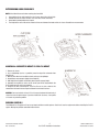
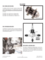
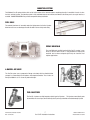
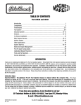
TABLE OF CONTENTS
Part #35520, #35530 and #35540
Introduction.................................................................................................................................................1
Components................................................................................................................................................2
Preliminaries...............................................................................................................................................3
Fuel System ................................................................................................................................................6
Induction System ......................................................................................................................................10
Sensors ....................................................................................................................................................13
O2 Sensor Installation ...............................................................................................................................14
Sensor Installation.....................................................................................................................................15
Main System Harness ...............................................................................................................................16
Ignition System .........................................................................................................................................21
Software Installation .................................................................................................................................26
Calibration Selection .................................................................................................................................27
Other Applications.....................................................................................................................................28
System Start-Up........................................................................................................................................28
Electronic Engine Management .................................................................................................................31
Pro-Flo Quick Tuning Guide.......................................................................................................................32
Optional PC Tuning....................................................................................................................................33
Calibration Module Flowchart ....................................................................................................................34
Parts and Part Numbers ............................................................................................................................35
Service & Warranty ...................................................................................................................................37
INTRODUCTION
Thank you for selecting the Edelbrock Pro-Flo Fuel Injection System. This Multi-Point Fuel Injection System has been designed for big-block
Chevrolet engines, and is designed to provide excellent performance, fuel economy, and maintenance-free operation. Installation of the
Edelbrock/ Pro-Flo Fuel Injection System involves modifications to the fuel system, ignition system, induction system, and possibly the valve train.
Although there are steps that must take place before others, the modifications do not necessarily have to be performed in a particular order.
Each modification is described in a separate section in this manual. Please study these instructions carefully before beginning installation of any
part of the Pro-Flo system.
If you have any questions, do not hesitate to call our
EFI Technical Hotline at (800) 416-8628, 7am-5pm PST, Monday-Friday
(In order to properly relay your call, please press 1 at the prompt to select Automotive
Products, followed by 3 to select EFI-Electronics then 1 again for Multi-Point EFI.)
Our EFI Technical Support staff can also be reached via email at: [email protected]
Part #35520, #35530, #35540
Rev. 8/11 AJ/mc
1
Pro-Flo EFI Installation Instructions
©2011 Edelbrock LLC
Brochure No. 63-35520
PRIMARY KIT COMPONENTS
❑
❑
❑
❑
❑
❑
❑
❑
❑
❑
❑
❑
❑
❑
❑
❑
❑
❑
❑
Electronic Control Unit/System ECU
Fuel rail assembly
Fuel pressure regulator
Main system harness
Intake manifold
Four barrel air valve
Idle Air Control (IAC) solenoid, integrated with air valve
Throttle Position Sensor (TPS), integrated with air valve
Installation package
Software CD
Calibration Module
Distributor
Fuel injectors
Ignition Harness
Manifold Absolute Pressure (MAP) Sensor
Manifold Air Temperature (MAT) Sensor
Coolant Temperature Sensor (CTS)
Oxygen (O2) sensor
USB/Serial Converter
Many Pro-Flo components, including the Manifold Absolute Pressure sensor, fuel pressure regulator, Coolant Temperature sensor, and the fuel
filter are standard OEM pieces. In the event that one of these parts needs to be replaced, you are likely to find a replacement at your local parts
supplier, in addition to your local Edelbrock dealer or directly from Edelbrock. For a list of part numbers, refer to the PART NUMBERS section at
the back of this manual.
Part #35520, #35530, #35540
Rev. 8/11 AJ/mc
2
Pro-Flo EFI Installation Instructions
©2011 Edelbrock LLC
Brochure No. 63-35520
TOOLS AND EQUIPMENT
HARDWARE AND PARTS CHECKLIST
Use the following checklist for items needed.
❑ Box and open end wrenches
❑ Socket set
❑ Distributor wrench
❑ Pliers (channel locks and hose clamp)
❑ Screwdrivers (regular and Phillips)
❑ Torque wrench
❑ Hammer
❑ Gasket scraper or putty knife
❑ Timing light
❑ Vacuum gauge
❑ Rags
❑ Water bucket
❑ Drill and bits
❑ Hole saw (1 1/4-inch or 1 3/4-inch)
❑ Tubing wrenches
❑ Tubing cutter
Use the following checklist for items needed.
❑ Intake gasket - Edelbrock #7202 for Rect. Port,
- Edelbrock #7203 for Oval Port
❑ Pipe plugs, if needed
❑ Edelbrock Gasgacinch #9300
❑ Loctite 598 OEM High Temperature Silicone Gasket (O2 Sensor
Compatible)
❑ Radiator coolant
❑ Wiring diagram for your vehicle
❑ Teflon tape or liquid Teflon thread sealer
❑ Manifold bolt kit #8564
❑ Throttle, Cruise Control & Trans. Kick-Down Mounting Bracket
#8031 (If Necessary see general catalog)
❑ 195° Thermostat
❑ Resistor type spark plugs (Use correct heat range for your
particular application
❑ Set of low-resistance spark plug wires with high EMI suppression
(DO NOT use solid core spark plug wires)
❑ Dynojet wideband commander (Optional, not included)
❑ DB9 Serial cable (Optional, not included)
❑ Fuel Pump (See Pump Recommendations)
❑ Fuel Filter
❑ Fuel Line
❑ Fuel Return Line
P R E L I M I N A RY C H E C K L I S T
1.
CAREFULLY STUDY AND UNDERSTAND ALL INSTRUCTIONS, BEFORE BEGINNING THIS INSTALLATION.
NOTE: This installation can be accomplished using common tools and procedures. However, you should have a basic
knowledge of automotive repair and modification and be familiar with and comfortable working on your vehicle. If you do
not feel comfortable working on your vehicle, it is recommended to have the installation completed by a professional
mechanic.
2.
Examine the Pro-Flo system for possible shipping damage. If damaged, contact your dealer immediately.
3.
These kits are designed for use with a standard Big Block Chevy V8 firing order.
4.
Check all threaded manifold holes.
5.
Check all internal manifold passages with a light and wire, making sure they are clean and unobstructed.
6.
Check automatic transmission shift points before removal of your stock manifold and adjust linkage after Edelbrock
manifold installation for same shift points (if needed).
NOTE::
We recommend that you refer to this checklist again after installation to be sure that you have completed all steps.
Part #35520, #35530, #35540
Rev. 8/11 AJ/mc
3
Pro-Flo EFI Installation Instructions
©2011 Edelbrock LLC
Brochure No. 63-35520
DETERMINING HOOD CLEARANCE
NOTE: Check hood clearance before removing stock manifold.
1.
2.
3.
4.
Use modeling clay or putty to make five small cones, two or three inches high.
Position cones on air cleaner at front, rear, each side, and on center stud.
Close hood to locked position and re-open.
The height of the cones indicate the amount of clearance between the hood and the air cleaner. Record these measurements.
MANIFOLD & CARBURETOR HEIGHT VS. PRO-FLO HEIGHT
1. Remove air cleaner.
2. Lay a straightedge (such as a yardstick) across the top of the carburetor from
front to back.
3. Measure from block and manifold end seal surfaces to straightedge.
4. Record these measurements (height A and height B).
5. Add height A and height B and divide by two to get the average height.
6. Assemble the manifold, air valve, and air cleaner you will be using to obtain the
A & B heights you will need to accomodate.
9. Compare the two measurements. If the Pro-Flo unit is taller, subtract this
amount from the hood clearance figure to determine new hood clearance.
CAUTION: You must maintain at least 1/2-inch clearance between the hood and air
cleaner because of engine torque. If you have insufficient clearance, a low profile
air cleaner may solve the problem.
EMISSION CONTROLS
The Edelbrock Pro-Flo system will not accept stock emissions control systems. Check local laws for requirements before installing the Pro-Flo
system. Not legal on pollution-controlled motor vehicles.
Part #35520, #35530, #35540
Rev. 8/11 AJ/mc
4
Pro-Flo EFI Installation Instructions
©2011 Edelbrock LLC
Brochure No. 63-35520
FUEL REQUIREMENTS
Because the Pro-Flo system uses an Oxygen sensor, you must use unleaded fuel only. Leaded fuels will damage the O2 sensor. If you do use
leaded fuel in your vehicle, do not install the O2 sensor and do not operate the vehicle in the closed loop fuel mode.
AUTOMATIC TRANSMISSION CHECK
For best performance, economy, and emissions, the shift point must be checked before and after the manifold change.
NOTE: This check should be performed ONLY at a sanctioned drag strip or test track.
With the shifter in Drive, accelerate to wide open throttle from a standing start. Hold in this position, noting speedometer MPH when the
transmission makes the first 1-2 shift. After the Pro-Flo system has been installed, make the same test, again noting MPH of this first shift.
If adjustment is necessary, we recommend use of the Edelbrock Throttle, Cruise Control, & Transmission Kick-Down Mounting Bracket #8031.
The Turbo 350 and Turbo 200 feature a window to accommodate user adjustment of shift points at WOT.
The transmissions in certain vehicles require precise adjustments. We recommend that you consult a reputable transmission shop for final
adjustments once the Pro-Flo system has been installed. Incorrect shift points can result in transmission damage.
ENGINE CLEANING
Edelbrock recommends that the Pro-Flo system be installed on a clean engine in order to prevent dirt from falling into the engine lifter valley or
intake ports.
1. Cover ignition. Use engine degreaser and a brush to thoroughly clean the manifold and the area between the manifold and valve covers.
2. Rinse with water and blow dry.
EXHAUST MANIFOLD HEAT RISER VALVE
If your vehicle is equipped with an exhaust manifold heat riser valve (typically located on the passenger side of the vehicle below the exhaust
manifold), remove the valve for proper operation. If applicable, any air injection tubes must be removed and holes in the exhaust manifold
plugged for proper operation.
HEADERS
For best performance, headers are recommended. For this application, header primary tube diameter should be 1-3/4 inch, approximately 31
inches long and terminating into a 3 inch collector. The remainder of the exhaust system should consist of dual exhaust and tail pipes, at least 21/4 inches in diameter with low back pressure mufflers.
COOLING SYSTEM
The minimum requirements for the thermostat are 180° but the ideal thermostat is 195°. When the vehicle is at 175 or below, system will stay
in cold start mode and not perform properly.
Part #35520, #35530, #35540
Rev. 8/11 AJ/mc
5
Pro-Flo EFI Installation Instructions
©2011 Edelbrock LLC
Brochure No. 63-35520
FUEL SYSTEM
FUEL PUMP (NOT INCLUDED)
The Edelbrock Pro-Flo 2 EFI system is capable of handling a wide
variety of engine power levels. It is important that you match your
particular engine combination with a pump sufficient to your needs.
Please refer to the following list to make the best determination for
your engine:
Up to 600 HP: aprox. 57 GPH @ 45 psi - Edelbrock #3594
Up to 800 HP: aprox. 80 GPH @ 45 psi - Edelbrock #1790
Up to 1500 HP: aprox. 120 GPH @ 45 psi - Edelbrock #1794
Fuel Pump #1790
FUEL PRESSURE REGULATOR
The Edelbrock Pro Flo system includes a fuel pressure regulator part
number 1729. The fuel that is not injected is returned to the fuel tank
via the return fuel line. The fuel pressure can be adjusted with the
screw at the top of the regulator.
FUEL SUPPLY & RETURN LINES
The installer is responsible for providing supply and return lines.
-6 AN (#35520) or -8 AN (#35530 & #35540) fittings are provided at
the front of the fuel rails (inlet) and bottom of the fuel pressure
regulator (outlet). Be sure to route all fuel lines away from exhaust
and moving parts (belts, fans, etc.).
Part #35520, #35530, #35540
Rev. 8/11 AJ/mc
6
Pro-Flo EFI Installation Instructions
©2011 Edelbrock LLC
Brochure No. 63-35520
INDUCTION SYSTEM
The Edelbrock Pro-Flo system delivers fuel and air to the engine via the induction system consisting primarily of a manifold, 4-barrel air valve,
fuel rails, and fuel injectors. The induction system is fully assembled, tested, seal checked, and flowed at the factory and is as easy to install as a
manifold. DO NOT DISASSEMBLE any of these components during installation.
FUEL RAILS
The extruded aluminum rail assembly routes the high pressure fuel to the injectors.
Aluminum rails have an advantage over soft rails both in terms of style and safety.
INTAKE MANIFOLD
The new Edelbrock manifold used with the Pro-Flo system is very
similar to the successful Victor Jr. high-performance single-plane
manifold, but has been designed specifically for electronic fuel
injection applications.
4-BARREL AIR VALVE
The Pro-Flo system uses a progressive linkage valve body with four throttle blades
arranged in a conventional 4-barrel pattern, with staged secondaries. The air valve can
flow up to 1000 cfm at 1.5" of mercury when wide open.
FUEL INJECTORS
The Pro-Flo 2 systems use high impedance pintle-type fuel injectors. The injectors mount directly onto
the manifold, one at each port, for fuel delivery that is precisely controlled and instantaneously injected.
Part #35520, #35530, #35540
Rev. 8/11 AJ/mc
7
Pro-Flo EFI Installation Instructions
©2011 Edelbrock LLC
Brochure No. 63-35520
SENSORS
The Edelbrock Pro-Flo system interprets overall engine operating conditions and fuel/spark requirements based on readings from sensors that
measure specific engine conditions.
The Pro-Flo system includes five sensors:
1) Manifold Absolute Pressure
2) Manifold Air Temperature
3) Coolant Temperature
4) Throttle Position
5) Exhaust Oxygen (O2)
MANIFOLD AIR TEMPERATURE SENSOR
MANIFOLD ABSOLUTE PRESSURE SENSOR
The Manifold Air Temperature sensor, is a thermistor
device which measures air temperature. This sensor must
be installed into the air cleaner base. Drill the air cleaner
base with a 3/4” drill, deburr any sharp edges, install
MAT sensor grommet, then slide sensor into grommet.
The Manifold Absolute Pressure sensor, mounted on the air
valve with a bracket, converts air pressure (load) in the
manifold, to an analog signal sent to the ECU. For more
information on Manifold Absolute Pressure, refer to the
section on Speed Density Electronic Engine Management.
COOLANT TEMPERATURE SENSOR
The Coolant Temperature Sensor is a thermistor device
like the Manifold Air Temperature sensor. Resistance
varies as coolant temperature rises and lowers. The
Coolant Temperature Sensor is located at the front of the
manifold on the driver’s side.
Part #35520, #35530, #35540
Rev. 8/11 AJ/mc
THROTTLE POSITION SENSOR
The Throttle Position Sensor is an integral part of the
Pro-Flo throttle body and measures throttle angle.
8
Pro-Flo EFI Installation Instructions
©2011 Edelbrock LLC
Brochure No. 63-35520
ELECTRONIC CONTROL UNIT / SYSTEM ECU
The Electronic Control Unit (ECU) must be mounted away from
moisture, excessive heat, or vibration. Underneath the dashboard on
the passenger side, or behind the glove box are recommended
locations.
OXYGEN (O2) SENSOR
An oxygen sensor, installed on the header collector pipe, measures exhaust gas oxygen content and is used by the ECU to manage fuel delivery
under closed loop control. Installing the sensor requires drilling a 1/2-inch hole in the passenger-side header collector. The sensor is held in
place with the provided fitting which must be professionally welded into place. The red-lean/green-rich light on the Calibration Module is also
controlled by the O2 sensor. The O2 sensor is connected to the Main System Harness by Connector J18. For installation details, refer to the FUEL
SYSTEM section of this manual.
NOTE: The Pro Flo system is now capable of using either a narrow
band or wide band O2 sensor. The difference between a narrow band
and wide band O2 sensor is the range over which the sensor is
accurate. A narrow band sensor is basically a switch that only tells
the ECU if the air fuel ratio (AFR) is richer or leaner than 14.7 to 1. A
wide band sensor/controller typically has a linear voltage output that
is accurate over a range of 10 to 20:1 AFR. The included wideband
sensor calibration is for use with the Dynojet Wide Band Commander
Air Fuel Ratio Monitor. See http://www.widebandcommander.com for
more information. To select the wideband option, install the included
O2 select jumper as shown in the next section. To use the default
narrow band option, leave the jumper off. A dust cap is provided for
protection when the connector is not in use. The wideband sensor
input is located on pin 31 of the larger 34 pin main ECU connector.
Using the supplied ECU terminal pigtail, insert the pigtail by
depressing the white terminal lock on the connector. Insert the
terminal into pin 31, then close the terminal lock by pushing it in the
other direction. Connect the wideband controller output to the pigtail.
O2 SELECT
JUMPER
INSTALL FOR WIDEBAND (OPTIONAL)
J3
O2 SENSOR
SELECT
O2 SELECT
JUMPER CAP
INSTALL FOR NARROW BAND (INCLUDED IN KIT)
Part #35520, #35530, #35540
Rev. 8/11 AJ/mc
9
Pro-Flo EFI Installation Instructions
©2011 Edelbrock LLC
Brochure No. 63-35520
O2 SENSOR INSTALLATION
The exhaust gas oxygen content is determined by the oxygen sensor. The sensor signals the ECU, which compensates when the air/fuel mixture
is either rich or lean.
NOTE: It is recommended that the O2 sensor installation be performed by a professional muffler shop.
1.
Double check header gaskets, replacing if necessary.
2.
Drill a 1/2-inch to 9/16-inch hole in the passenger-side header collector reducer, as close to the header flange as possible. (1" to 3" away)
NOTE: Before drilling, make sure the O2 sensor will be mounted horizontally and within reach of the harness connector. Check to ensure
adequate clearance for the sensor, taking into consideration engine movement.
3.
Fit the provided fitting into the hole in the exhaust pipe and weld into place.
4.
Once it has been welded into place, clean the threads in the center of the fitting. If your exhaust is coated tap bung threads to ensure a
good ground for the 0/2 sensor.
5.
Thread the O2 sensor into the fitting. A high-heat anti-seize compound is included and needs to be applied to the sensor threads.
NOTE: The O2 sensor has 18mm x 1.25 spark plug threads.
6.
Attach the O2 sensor to the main system harness. Refer to the MAIN SYSTEM HARNESS section of this manual.
NOTE: UNLEADED FUEL MUST BE USED ONCE THE O2 SENSOR HAS BEEN INSTALLED.
HARNESS INSTALLATION
1.
Inspect the Main System Harness, making sure that all connectors and grounds are properly in place.
2.
Because the harness extends from the engine compartment into the passenger compartment, a hole must be drilled in the firewall on the
passenger side. Cut two overlapping 1 1/4-inch holes on a 1-inch center in the firewall. Saw the pointed edges to create an oval-shaped
hole.
NOTE: An alternative to this method is to cut a single 1 3/4 inch hole.
3.
Extend the fuel pump relay, ECU connector, and Calibration Module relay through the firewall hole into the passenger compartment.
NOTE: The T-connectors at the joints of the Main System
Harness are closed by snap fasteners which can be opened by
hand or with a flathead screwdriver. Once open, the T-connectors
can be rotated for ease of installation, if necessary.
4.
The aluminum plate included on the harness mounts over the
firewall hole using four hex head sheet metal screws.
NOTE: Start the screw holes with a pointed punch or small drill.
5.
The wire harness is assembled with the aluminum plate flush
against a T-connector. The black plastic casing on the wire
harness can be cut to allow the plate to slide up the harness to
the correct location. Once the harness is in place, the casing
should be reattached on both sides of the firewall.
CAUTION: When feeding the wire harness through the firewall,
be careful to not damage the wires against the cut sheet metal.
6.
A rubber grommet is provided to protect the wires in the
aluminum plate. Use RTV to seal the plate to the firewall.
7.
Install all connectors according to the schematic and harness
layout on the following pages
Part #35520, #35530, #35540
Rev. 8/11 AJ/mc
The fuel injector connectors are identical, but they are
placed in logical sequence. Refer to the diagram when
installing the harness connectors to the fuel injectors.
10
Pro-Flo EFI Installation Instructions
©2011 Edelbrock LLC
Brochure No. 63-35520
MAIN SYSTEM HARNESS
This diagram illustrates the entire Pro-Flo Main System
Harness.
Part #35520, #35530, #35540
Rev. 8/11 AJ/mc
11
Pro-Flo EFI Installation Instructions
©2011 Edelbrock LLC
Brochure No. 63-35520
Part #35520, #35530, #35540
Rev. 8/11 AJ/mc
12
Pro-Flo EFI Installation Instructions
©2011 Edelbrock LLC
Brochure No. 63-35520
HARNESS LAYOUT
Part #35520, #35530, #35540
Rev. 8/11 AJ/mc
13
Pro-Flo EFI Installation Instructions
©2011 Edelbrock LLC
Brochure No. 63-35520
The connector on left end (as drawn) of this 10-foot fuel pump wiring harness attaches to the Main System Harness. The two connectors on the
right connect to the positive (+) and negative (-) terminals on the fuel pump. A sleeve and tie-wrap are provided to fit over the positive terminal
once the connector is installed. This sleeve prevents the clamp from shorting the fuel pump terminals.
10'
BLK
BLK
B A
+
ORN
ORN
IGNITION SYSTEM
The ignition harness is attached to the main harness with the connector, as shown at left below, and at the coil with the ring terminals on the
right below. The ground goes to the rear of the cylinder head. Connect the red and brown wires to the positive and negative terminals of the coil
as shown below.
RED (COIL +)
IGNITION HARNESS
TO MAIN HARNESS
J6 IGNITION COIL
BROWN (COIL -)
GROUND TO REAR
CYL HEAD
ADDING AFTERMARKET IGNITION
If you are wishing to use a MSD 6AL or MSD 6-Digital ignition with your Pro-Flo fuel injection, follow the wiring diagram below.
NOTE: When installing the MSD box, keep the red battery lead, the main MSD box, and the power leads to the ignition amplifier AWAY from the
ECU and it’s wires. Failure to do so will cause serious communication and running issues.
TYPICAL 2 TERMINAL
COIL MSD EXAMPLE
Part #35520, #35530, #35540
Rev. 8/11 AJ/mc
14
Pro-Flo EFI Installation Instructions
©2011 Edelbrock LLC
Brochure No. 63-35520
IGNITION SYSTEM
DISTRIBUTOR TESTING
1.
Install the ECU and wiring harness and make all connections except the
distributor and ignition coil.
2.
Disconnect electrical connections at the fuel pump. Unplug the
10-foot fuel pump harness from the Main System Harness. Refer to the
MAIN SYSTEM HARNESS section of this manual for details.
3.
The Pro-Flo Calibration Module will receive power and display an RPM:
220 reading, among other parameters.
4.
Connect the distributor to the wiring harness and spin the distributor
gear by hand. If the distributor sensor is operating properly, the main
fuel pump relay will click on. When the distributor stops spinning, the
Calibration Module may display NO COMMUNICATION for approximately
2 seconds. This is normal and indicates that the ECU is waiting for the
next distributor signal before the allowed time expires.
5.
If the relay clicks on as indicated in step 5, re-install the distributor.
INSTALLING THE DISTRIBUTOR
1.
Rotate the crankshaft until cylinder #1 is coming up on the compression stroke. Stop turning when the crankshaft is 10° BTDC.
2.
Rotate the distributor shaft until the rotor points to the #1 on the distributor housing. The #1 plug wire will attach to the tower on the cap
directly above the #1 on the distributor housing.
3.
Install the distributor so that #1 on the cap is positioned where #1 was on
your previous distributor. You may need to remove and reinsert the
distributor a few times to align the distributor. Make sure that the
distributor seats down completely and has fully engaged the oil pump
drive.
#1 position
NOTE: If you are using an adjustable collar distributor: Loosen the adjustable
slip collar. Install the Distributor into the engine without the gasket
installed, make sure the oil pump shaft is fully engaged, and slide the slip
the collar down to sit against the manifold. Tighten the collar and remove
the distributor. Tighten the set screws on the collar and install the gasket.
4.
Lift the rotor by hand to make sure that there is adequate endplay. Lack of
endplay indicates that the rotor shaft is bottomed out on the oil pump
shaft.
5.
Lightly tighten the hold down clamp so that the distributor can still be
turned to determine final setting when checking the timing.
6.
Re-attach the distributor cap. Make sure the rotor is still pointing to #1.
7.
Install your spark plug and coil wires and connect the distributor to the
MAIN SYSTEM HARNESS.
NOTE: DO NOT use a Solid-Core type spark plug wire set, such as copper core, etc. You must use a suppression type spark plug wire.
Failure to use the correct wires will cause electrical interference with the engine control unit.
Part #35520, #35530, #35540
Rev. 8/11 AJ/mc
15
Pro-Flo EFI Installation Instructions
©2011 Edelbrock LLC
Brochure No. 63-35520
INSTALLING THE SOFTWARE
The software package included with the Pro Flo kit is required to load the initial calibration file into your ECU. An optional software package
called bEditor is also included on the supplied CD-ROM.
To install the software, load the supplied CD into your PC’s CD drive. The installation routine should auto run. Follow the onscreen prompts to
install the software.
eFlash is a stand alone system that can be used to load calibration files or different firmware versions onto an ECU using any Windows
compatible PC. A laptop is not required. The system includes a DC power source that can be plugged into any standard wall socket. It will
provide power to the ECU and allow two way communication without having to install the ECU in the vehicle. Tuning can then be done using the
handheld module. In addition to allowing flash programming, eFlash has several additional features that can be useful.
•
It displays all ECU data real time in one consolidated view.
•
It displays all calibration module trims and modifications in
one view so you can see them at a glance.
•
It allows Edelbrock tech support personnel to view your ECU
data real time using the iLink feature (internet connection
required)
•
It allows you to send your existing calibration file to Edelbrock
tech support personnel using the iLink feature (internet
connection required).
•
It allows the user to perform software updates if necessary.
To connect the ECU to your PC, plug the 34 pin ECU connector into the
ECU. The connector will only plug in one way. Connect the DB9 serial
connector to your PC either directly or through an extension cable (not
included). Plug the AC Power Adapter into a standard wall socket.
NOTE: A USB to Serial converter is included with the kit to be used if
your PC does not have a 9 pin serial port. Connect the USB end of the
adapter to your PC and the serial port (9 pin) end to the power adapter
harness. Follow the instructions included with the USB adapter to
install the appropriate drivers. Go to File - Port Settings in eFlash and
select the com port that matches the location of the adapter.
To open the eFlash utility double
click on the eFlash desktop icon.
Confirm that the ECU is connected and
communicating with eFlash. “ECU
Connected” should be displayed in the
lower left hand corner as shown to the right.
Part #35520, #35530, #35540
Rev. 8/11 AJ/mc
16
Pro-Flo EFI Installation Instructions
©2011 Edelbrock LLC
Brochure No. 63-35520
SELECTING THE PROPER CALIBRATION
Please refer to the calibration selection guide on the CD to determine the appropriate calibration for your application to load into the ECU. Use
caution if using the calibration included in the ECU from the factory as it may need extensive changes to achieve a proper tune and could cause
engine damage if not corrected.
NOTE: Edelbrock recommends a
minimum of 112° for lobe
seperation angle on all Pro-Flo
EFI applications. A value less
than this may make tuning more
difficult depending on the intake
duration.
To load a new calibration
file into the ECU, go to
File - Load New Map
The calibration files are saved in folders identified by kit part number.
Double click on the folder with your kit part number, then select the
calibration that corresponds to your camshaft duration. The eFlash utility
will load the calibration into your ECU. Follow the on screen prompts to
complete the process. When the software prompts you to cycle power,
simply remove the connector from the ECU, wait 5-10 seconds, then plug
it back in and hit OK. When finished, close the eFlash program and
disconnect the power adapter connector from the ECU. You are now
ready to connect the ECU to the vehicle harness. Additional information
can be found in the help file included in the software.
Part #35520, #35530, #35540
Rev. 8/11 AJ/mc
17
Pro-Flo EFI Installation Instructions
©2011 Edelbrock LLC
Brochure No. 63-35520
SYSTEM START-UP
Once the engine has been installed, there are a few procedures you must follow to break-in the system. Carefully performing these break-in
procedures will ensure best results and optimal performance.
Use this checklist to double-check the following areas BEFORE starting the car:
❑ Has the battery been reconnected?
❑ Has the radiator been refilled with coolant?
❑ Has the gas tank been refilled?
❑ Has the oil been filled?
❑ Have all linkages been reconnected?
❑ Have all wiring harness connectors been connected?
❑ Have all fuel lines been reconnected?
❑ Has the exhaust system been completely re-installed?
❑ Has the O2 sensor been installed and connected?
❑ Have resistor type spark plugs been installed (Champion RC-12YC or equivalent)?
❑ Has the calibration module been connected to the main harness?
Priming The Fuel Pump
Before the engine is started, the fuel pump must be primed to pressurize the system and purge the fuel line of all air.
1.
2.
3.
4.
5.
Turn ignition key to the ON position. You should hear the fuel pump go on. It will pump for 2 or 3 seconds and disengage.
Turn the key to the OFF position for 1 second.
Turn the key to the ON position again. The pump will go on for another 2 or 3 seconds.
Repeat this procedure until the pump has been cycled three or four times, and is primed. The tone of the fuel pump will change when all air
is out of the fuel system.
If there is no tone, or no change in tone, the system is not priming. Check the entire fuel system for leaks, from the fuel tank to the
injectors.
Testing The Sensors
Before starting the engine, test all sensors.
1.
Turn the key to the ON position with the Calibration Module connected. The display will read:
RPM: 0 FUEL: 0.0 mS
VAC: 0.0” Hg
SPK: 10°
NOTE: A vacuum reading of other than 0.0” Hg may be displayed depending upon barometric pressure and air temperature. At extreme
altitude, the vacuum reading may be as high as 5.0” Hg.
2.
Push the UP ARROW key once to display.
TH2O: 76°F
TAIR: 77°F
TPS: 13°
Volt: 12.0
NOTE: The water and air temperatures displayed will vary depending on ambient conditions. The system voltage will vary depending on the
condition of the battery.
3.
Move the throttle to test the Throttle Position Sensor (TPS). The TPS reading should vary depending on throttle angle.
4.
If the calibration module goes blank while cranking, the system is losing power. Check the Pink/Black wire attached to the 3 Amp fuse for
+12V power with the ignition in the crank position and the run position for proper operation.
Part #35520, #35530, #35540
Rev. 8/11 AJ/mc
18
Pro-Flo EFI Installation Instructions
©2011 Edelbrock LLC
Brochure No. 63-35520
Timing Adjustment
Use a timing light to re-time your engine. The following steps must be performed after the
induction system has been installed and the distributor has been converted and re-installed. Refer
to the INDUCTION SYSTEM and IGNITION SYSTEM sections of this manual.
1.
Remove spark plug from Number One cylinder.
2.
Remove coil wire from distributor and ground it.
3.
THIS STEP REQUIRES TWO PEOPLE OR USE OF A REMOTE STARTER SWITCH. While one
person rotates the engine by slowly bumping the starter, the other holds his finger over the
Number One plug hole until compression is felt.
4.
Continue to bump starter until timing mark on the crankshaft pulley shows approximately 10
degrees Before Top Dead Center.
5.
Position rotor to approximately align with the Number One cylinder plug wire terminal in distributor cap. Check that the leading edge of the
narrow tooth on the shutter wheel (as the shutter wheel rotates clockwise) is centered in the sensor. Refer to the IGNITION SYSTEM section
in this manual for details.
Setting Base Spark Advance
Use a timing light and the Pro-Flo Calibration Module to
accurately set timing.
1.
Start the engine
2.
The Calibration Module screen will display this screen:
3.
Press the DOWN ARROW key once to reach this screen:
4.
Press the ENTER key to display this screen:
5.
Press the UP ARROW key six (6) times until the module displays this screen:
6.
Press the ENTER key. Press either ARROW key and the screen will display Base Tim’g set: ON.
7.
Set the base timing using a timing light and engine running at 1500rpm. Turn the distributor until 10° advance is set.
8.
Press the UP ARROW or DOWN ARROW key to turn Base Tim’g set to OFF.
RPM: ø FUEL: 0.0 ms
VAC: 0.0"Hg SPK: 10°
<MISC.MODIFIERS>
ENTER to select
Target Idle RPM:xxxx
MODE
= SCROLL ENTER
Base Tim'g set: OFF
MODE
= SCROLL ENTER
WARNING: DO NOT DRIVE THE VEHICLE WITH THE BASE TIM’G SET ON. SERIOUS ENGINE DAMAGE MAY RESULT
NOTE: If you use an advance-type timing light, the degrees advance shown on the Calibration Module (SPRK:) should always agree with the
actual reading at the crank with the timing light.
9. Press the MODE key. You can now leave this screen using the UP ARROW or DOWN ARROW keys.
Idle Adjustment
This procedure is a general recommendation, intended to help you tune up your Pro-Flo® system.
NOTE: In manual transmission cars, this procedure must be followed with the car in Neutral and with the clutch pedal pressed. In automatic
transmission cars, this procedure must be followed with the car in Drive and with the brake pedal pressed.
Part #35520, #35530, #35540
Rev. 8/11 AJ/mc
19
Pro-Flo EFI Installation Instructions
©2011 Edelbrock LLC
Brochure No. 63-35520
Idle Calibration Procedure
• Prior to idle calibration, you need to have completed the "System Start-Up" procedure
• Warm up engine to at least 175°F.
Idle Control
• Using the calibration module, Select MISC. MODIFIERS and, Set Idle Control OFF.
Set Idle Mechanical Stop
• Set the mechanical stop screw so that idle speed in park/neutral is 50-100 RPM higher than you want the engine to actually idle in gear
with the idle control turned on. Typically 600 - 1000 RPM depending on the installed camshaft.
• We find 650 RPM a good idle for our #3512 (with Performer-Plus camshaft) calibration.
Set Throttle Position Sensor
• Loosen the two Throttle Position Sensor (TPS), mounting screws, and rotate the TPS sensor to a setting of 13 degrees as observed on
the Calibration Module. This setting must be at 13 degrees after the idle adjustment is completed.
Set Idle Fuel Modifier and Idle Spark Modifier
• Using the calibration module, Select MISC. MODIFIERS and adjust Idle Spark and fuel Modifiers to obtain best idle quality. Idle quality
will vary with engine design. Fuel and Spark setting will interact, particularly when you approach best settings.
• You must establish a smooth idle prior to using Idle Control. Otherwise, the RPM will surge when Idle Control is turned on.
Save Calibration
• Re-check that the TPS setting is 13 Degrees.
• Using the calibration module, Select MISC. MODIFIERS
• Set IDLE CONTROL ON. Set TARGET IDLE to the same RPM established by the idle stop screw.
• Save calibration settings to “A”
Idle Speed Activity
• Displayed on the calibration module, (Second Data Screen). The displayed value represents the amount of air that is bypassing the
throttle blades of the air valve, Normal values range from 5% to 75%. This ensures that the computer can increase or decrease the idle
air flow to control idle speed.
• If your have established a "good" idle set up, the RPM will remain nearly constant between in-gear and out-of-gear. The Idle Speed
Activity will change 10- 30% as it adjusts the idle speed.
• The value of Idle Activity is 20% when Idle Speed Control is off.
Idle Speed Activity Modifier
• This function is locked out when Idle Control is off as indicated by "XXXX" in the Target idle display on the Calibration Module Display.
• The Idle Speed Activity Modifier biases the Idle Activity duty cycle, +/50%, this has the effect of changing RPM control loop response time.
• We recommend that this value be set to zero modification except in extreme cases.
Part #35520, #35530, #35540
Rev. 8/11 AJ/mc
20
Pro-Flo EFI Installation Instructions
©2011 Edelbrock LLC
Brochure No. 63-35520
ELECTRONIC ENGINE MANAGEMENT
The Edelbrock Pro-Flo system uses the Speed-Density method of electronic engine management, in which fuel and spark requirements are
based on engine speed (RPM) and engine load (manifold pressure and temperature).
The Electronic Control Unit (ECU) receives signals regarding engine speed (from the distributor), and the three load factors consisting of coolant
temperature (ECT), Manifold Absolute Pressure (MAP) and air temperature (MAT). Once the ECU has determined the engine operating point (RPM
and Load factor), it uses tables programmed into it to instantly calculate correct spark advance and injector pulse width.
The Pro-Flo system displays vacuum rather than the less-familiar manifold pressure. This vacuum reading is based on the following SAE
standard atmosphere:
Barometer 29.5 in Hg
Temperature 77°F
Because of this, the vacuum figures displayed on the Calibration Module may differ from the vacuum indicated by a true vacuum gauge,
particularly at extreme high or low altitude.
FUEL MODIFIER TABLE
The Calibration Module allows you to modify the fuel and spark
tables at various engine speeds and levels of vacuum. These
SPARK MODIFIER TABLE
tables may be used for recording your modifications to the base
table with your own fuel pulse width and spark advance figures.
Part #35520, #35530, #35540
Rev. 8/11 AJ/mc
21
Pro-Flo EFI Installation Instructions
©2011 Edelbrock LLC
Brochure No. 63-35520
PRO-FLO QUICK TUNING GUIDE
This guide is based on our simple graph that shows the 24 fuel cells that you can tune in to result in a clean and powerful engine. We
recommend when you have your Pro-Flo installed, you have the idle tune up completed and then drive the vehicle to determine what amount of
tuning is needed for general driving. If the unit is driveable, this is the method to use for ease of tuning. On page 21 of this installation manual,
there is a fuel grid that can be used as the map on which to locate and then tune any drivability problems. Simply drive the vehicle and note any
areas that have problems. Circle those areas as a baseline.
When circling the area where a problem exists, you are circling the RPM and Vacuum reading that is present when the problem occurs.
Note whether it is running rich (green light) or lean (red light) at each problem area. Once any problem areas have been located and noted rich or
lean, go into the Miscellaneous Modifiers menu and turn off the Closed Loop Fuel, exit, go to Fuel Modifiers, and then into Global Fuel. Now drive
the vehicle and drive back to each problem area. When driving in a problem area, add or subtract fuel to obtain the smoothest operation at that
driving point. Write down the quantity (plus or minus) of fuel required to achieve a smooth operation. When all the problem areas have been
noted, and the amount of fuel required to achieve smooth operation has been noted at each problem area, you may now do each adjustment one
at a time to achieve a complete tune up.
To input this information, you will need to make sure the Closed Loop Fuel is in the OFF position. Go to each area and enter the information.
If you have found a problem that is not exactly in the center of one of the fuel cells, you will still be able to tune the area by using the Surround
and Conquer method for properly managing the fuel curve. Listed below is an example of this method:
Assume that you have found a problem area at 2500 RPM and 15 inches of Vacuum. This is not an area where you can address the
problem directly. In this scenario, we will say the unit is showing a lean condition (red light). In which case, fuel will need to be added.
We will also say that when driving and using the Global Modifier to find the exact amount of fuel required, it was determined that the
amount needed was plus ten percent (+10%). In the Surround and Conquer method, you will add fuel at the four locations surrounding
the problem area. This is shown in the figure below:
ENGINE RPM
1000
2000
3000
4000
5000
VACUUM
(WOT) 0
Problem Area
6
12
X
7000
In this example, tune
by adding 10% fuel at
each area marked by
an “X”, surrounding
the problem area.
X
LEAN
18
X
X
When the required amount of fuel has been added at each surrounding fuel cell, complete the operation by returning to the Miscellaneous
Modifiers menus, and turning the Closed Loop Fuel ON. Press the SAVE key, then the ENTER key. The hand-held unit will show SAVING IN
PROGRESS. Repeat this procedure at each problem area to complete the tune up.
Part #35520, #35530, #35540
Rev. 8/11 AJ/mc
22
Pro-Flo EFI Installation Instructions
©2011 Edelbrock LLC
Brochure No. 63-35520
CALIBRATION MODULE FLOWCHART
Part #35520, #35530, #35540
Rev. 8/11 AJ/mc
23
Pro-Flo EFI Installation Instructions
©2011 Edelbrock LLC
Brochure No. 63-35520
PART NUMBERS
Many of the components of the Pro-Flo system are available separately. Many are standard OEM
parts. In the event that one of these parts need to be replaced, you are likely to find a
replacement at your local parts supplier, in addition to your local Edelbrock dealer or directly
from Edelbrock.
Edelbrock Pro-Flo
Fuel Rails............................................................................................................Edelbrock #3633
Manifold Absolute Pressure sensor ...................................................................Edelbrock #36019
Manifold Air Temperature sensor (Push-In) .........................................................Edelbrock #3588
Coolant Temperature sensor .............................................................................Edelbrock #36012
Throttle Body ....................................................................................................Edelbrock #39783
IAC Motor..........................................................................................................Edelbrock #36017
Throttle Position sensor ....................................................................................Edelbrock #36018
Oxygen (O2) sensor ...........................................................................................Edelbrock #36013
Fuel pressure regulator.......................................................................................Edelbrock #1729
Fuel injectors (set of eight)..................................................................................Edelbrock #3686
Fuel injectors (one) .............................................................................................Edelbrock #3687
Mallory Distributor.........................................................................................Edelbrock #54-3564
Calibration Module ........................................................................................Edelbrock #37-9804
Calibration Module Cord/Plug........................................................Edelbrock #37-9803/#37-3719
Part #35520, #35530, #35540
Rev. 8/11 AJ/mc
24
Pro-Flo EFI Installation Instructions
©2011 Edelbrock LLC
Brochure No. 63-35520
COMPLETE PRO-FLO SYSTEM PARTS
( 1) Mallory Distributor
( 1) Manifold Absolute Pressure sensor
( 1) Manifold Air Temperature sensor
( 1) Coolant Temperature sensor
( 1) Oxygen (O2) sensor
( 1) Fuel pressure regulator
( 1) Throttle Body w/ TPS
( 1) Main system harness
( 1) Intake manifold
( 1) MAP Sensor bracket
( 2) Fuel rail
( 8) 60 lb/hr fuel injector
( 1) Ignition Harness
( 1) Communication cord adapter
( 1) Pro-Flo2 ECU
( 1) Calibration module
( 1) Calibration module cord
( 1) Fuel pump blockoff plate
( 1) Russell Pro-Classic EFI crossover fittings and hose
Part #35520, #35530, #35540
Rev. 8/11 AJ/mc
25
Pro-Flo EFI Installation Instructions
©2011 Edelbrock LLC
Brochure No. 63-35520
SERVICE
In the event that your Edelbrock Pro-Flo System should need servicing, return the unit pre-paid to the
Edelbrock Service and Repair facility at 2700 California Street, Torrance, CA 90503. Do not attempt to
disassemble or service the components of the Pro-Flo system yourself. Doing so may void the warranty.
WARRANTY
It is the constant endeavor of the Edelbrock Corp. to provide our customers with the highest quality
performance products. Edelbrock warrants the Edelbrock Pro-Flo System to be free from defects in both
workmanship and materials for a period of one year from date of purchase, provided that the product is
properly installed and subjected to normal use and service, is not used for racing or competition purposes
and that the product is not modified or altered in any way unless specified by our instructions. Our
warranty service and repair facility is located at 2700 California Street, Torrance, CA 90503. Customers
requiring warranty assistance should contact the dealer from whom they purchased the product. In turn,
the dealer will contact Edelbrock, and we will determine the method of satisfying the warranty. Should
Edelbrock determine that the product be returned to the factory, it should be accompanied by proof of
purchase and a clear description of the exact problem. The product must be returned freight pre-paid. If a
thorough inspection of the product by the factory indicates defects in workmanship or material, our sole
obligation shall be to repair or replace the product. This warranty covers only the product itself and not the
cost of installation or removal.
EDELBROCK CORP. SHALL NOT BE LIABLE FOR ANY AND ALL CONSEQUENTIAL DAMAGES OCCASIONED
BY THE BREACH OF ANY WRITTEN OR IMPLIED WARRANTY PERTAINING TO THIS SALE, IN EXCESS OF THE
PURCHASE PRICE OF THE PRODUCT SOLD.
If you have any questions regarding this product or installation, please contact our Technical Department
from 7:00am - 5:00pm, Pacific Standard Time, Monday through Friday at:
Tech Telephone: (800) 416-8628
Fax: (310) 9 72-2730
Edelbrock Corporation
2700 California Street
Torrance, CA 90503
Part #35520, #35530, #35540
Rev. 8/11 AJ/mc
26
Pro-Flo EFI Installation Instructions
©2011 Edelbrock LLC
Brochure No. 63-35520