1
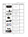
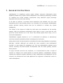
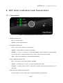
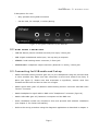
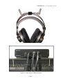
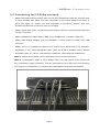
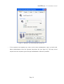
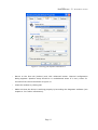
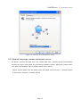
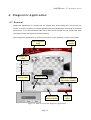
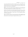
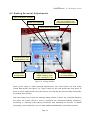
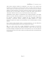
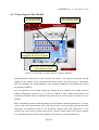
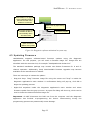
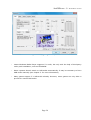
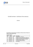
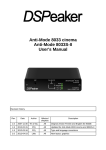
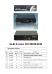
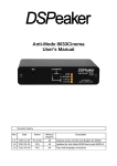
HeaDSPeaker - 5.1 DSP Headphone System With Head Tracking USER'S MANUAL Revision history Rev. Date Author Chapters 01.11 24.03.09 LM All Description Translated version HEADSPEAKER – 5.1 HEADPHONE SYSTEM Part # Photo Description 1 2 DSP unit Head tracking sensor (for headphones) USB cable, 3 A plug mini USB (5PIN) M 4 5 6 7 8 230V – USB adapter 3.5 mm 3.5 mm audio cable Software installation media Volume attenuator 3.5 mm 2 x RCA audio cable Page 2 Checked HEADSPEAKER – 5.1 HEADPHONE SYSTEM 1. G eneral in stru ction s HeaDSPeaker 5.1 headphone system makes realistic, immersive multichannel audio playback possible using regular stereo headphones. The underlying technology is based on modeling the human auditory mechanisms using advanced signal processing algorithms and real-time head tracking. To be able to produce a surround sound experience that satisfies even the most demanding users, head tracking feature is a necessity. For this purpose, HeaDSPeaker system provides tracking sensors that can be attached to virtually any regular headphones. The ”brains” of the system is a DSP unit, which acts as a transmitter for the tracking sensors. DSP unit processes multichannel audio signal in such a way that the user perceives sound directions as if the sound was actually played back using a set of surround loudspeakers. HeaDSPeaker supports lossless 5.1 (or 7.1) PCM-audio via USB-bus, or alternatively surround-encoded multichannel audio via analog stereo connector. Analog stereo audio will be decoded to multichannel format using DSPeaker's proprietary DSP-logic -decoder. DSP-logic can decode the most commonly used multichannel formats in a way suitable for headphone use. This way HeaDSPeaker supports sound sources including surround-encoded TV-broadcasts and the latest gaming consoles among others. To enjoy surround sound at the maximum, it is recommended to take a couple of minutes to configure the system based on personal qualities. HeaDSPeaker package contains the required computer software for easy configuration and diagnostics. At the moment, only Windows XP and Vista plattforms are supported. A Macintosh version is under development. Page 3 HEADSPEAKER – 5.1 HEADPHONE SYSTEM Figure 1: A recommended placement for the DSP unit is at the top of the display device Figure 2: Using the spring clip Page 4 HEADSPEAKER – 5.1 HEADPHONE SYSTEM 2. D S P U nit' s Indi c ator s a nd C o nne ction s 2.1 Front p anel 1 2 3 4 5 Figure 3: front panel indicators of the DSP unit 1 AUDIO indicator led • OFF = no audio input • GREEN = audio input present 2 TRACKER indicator led • OFF = direct stereo audio (no processing) • GREEN = head tracking functioning normally • ORANGE = errors in tracking or tracking disabled. Head tracking is automatically turned off when no audio is present for a while, when connected via USB. • RED = static 5.1-auralization, head tracking disabled 3 PCM / ANALOG indicator led • OFF = only stereo sound from USB is available • GREEN = multichannel (5.1 tai 7.1) audio available from USB • ORANGE = analog input is active. DSP-logic decodes surround-encoded audio to 5 channels. 4 Head tracker ultrasound-transmitter • Must be within ”line-of-sight” with sensors attached to headphones Page 5 HEADSPEAKER – 5.1 HEADPHONE SYSTEM 5 Microphone for voice • Only operates during USB connection • Can be used, for example, in online-gaming Figure 4: rear panel connectors of the DSP unit 2.2 R e ar P a n el C onne ctor s • LINE IN: Stereo (stereo encoded surround) line input, 3.5mm jack • USB: digital multichannel audio input / set-up using a computer • SENSOR: head tracking sensor connector, 3.5mm jack • HEADPHONES: headphone output connector (binaural 5.1-audio), 3.5mm jack 2.3 C o nne ctin g for U S B-a udio a nd S et-up • Attach the head tracking sensors (part #2) to your headphones using the provided strip or other suitable way. Make sure that connection is secure and sensors are firmly in place (see figure 5). Please note that orientation is significant, sensors must face towards the DSP unit and have a clear line-of-sight. • Attach signal cable (part #5) between head tracking sensor's connector and DSP-unit's ”sensor” connector. • Attach headphone's signal cable to DSP-unit's “headphones” connector (figure 6). • Attach USB-cable (part #3) between a computer and the DSP-unit. • Insert installation media into computer's drive and proceed with software installation (see chapter 3. for further information). • Perform the set-up procedure using the diagnostic application as described in chapter 4. Page 6 HEADSPEAKER – 5.1 HEADPHONE SYSTEM Figure 5: tracking sensors securely attached to headphones Figure 6: connections in USB-audio mode Page 7 HEADSPEAKER – 5.1 HEADPHONE SYSTEM 2.4 C o nne ctin g for 5.0 D olby s urround • Attach the head tracking sensors (part #2) to your headphones using the provided strip or other suitable way. Make sure that connection is secure and sensors are firmly in place (see figure 5). Please note that orientation is significant, sensors must face towards the DSP unit and have a clear line-of-sight. • Attach signal cable (part #5) between head tracking sensor's connector and DSP unit's ”sensor” connector. • Attach headphone's signal cable to DSP unit's “headphones” connector (figure 6). • Attach USB voltage adapter (part #4) between a mains output and DSP unit's USB connector. • Attach “line-in” to headphone output or line output of the signal source (TV, Xbox360, Playstation 3 etc) using appropriate cable (part #8 or other suitable cable). Volume attenuator (part #7) can be used between headphone output and the headphones. Note 1: Please do not attach volume attenuator in the sensor-connector! Note 2: If headphone output is used, please make sure that sound source doesn't do any unnecessary signal processing. That can potentially prevent DSP-logic from decoding from stereo to multichannel, or interfere with HeaDSPeaker's dynamic auralization. Figure 7: connections in Dolby surround mode Page 8 HEADSPEAKER – 5.1 HEADPHONE SYSTEM 3. S oft w are In st allation Connecting the DSP unit to a computer's USB port will initiate the installation of required system drivers. To make personal adjustments, it is highly recommended to install the provided diagnostic software also. To install the diagnostic software, place the provided installation disc in the disc drive. Installation procedure should start automatically. If it doesn't, autorun feature is disabled in the operating system. In this case, view the contents of the installation disc in file browser and launch the installer program manually. Installer program will start by presenting a list of optional components to install. It is advisable to make a full install. Next, the program allows to define a destination directory. When you're ready, click install to finish the installation. 3.1 S o u nd S ettin g s U n der Windo w s X P After the software installation has completed, attach the DSP unit to a vacant USB port. System should automatically identify the device and install any necessary hardware drivers. After that, please make sure that HeaDSPeaker has the default sound device status. • Launch control panel from the Start menu. • Open sound devices. A window similar to that shown in figure 8 should pop up. Page 9 HEADSPEAKER – 5.1 HEADPHONE SYSTEM Figure 8: Windows XP sound and audio properties • If the topmost line displays any other device than HeaDSPeaker, open up Audio tab. Select HeaDSPeaker from the topmost drop-down list (see figure 9). This way sound output from the computer goes through HeaDSPeaker whenever possible. Page 10 HEADSPEAKER – 5.1 HEADPHONE SYSTEM Figure 9: selecting the default sound device • Return to the first tab (Volume) and click Advanced button. Channel configuration dialog appears. Speaker setup should be in multichannel state. If it isn't, select 5.1 surround from the list as shown in figure 10. • Close the window by clicking OK. • Make sure that the device is working properly by launching the diagnostic software (see chapter 4. for further information). Page 11 HEADSPEAKER – 5.1 HEADPHONE SYSTEM Figure 10: selecting surround speaker setup 3.2 S o u nd S ettin g s U n der Windo w s Vi st a As above, connect the DSP unit to a vacant USB port. System should automatically identify the device and install any necessary hardware drivers. After that, please make sure that HeaDSPeaker has the default sound device status. • Launch control panel from the Start-menu and select sound devices. A window similar to that shown in figure 11 should pop up. Page 12 HEADSPEAKER – 5.1 HEADPHONE SYSTEM Figure 11: Sound and audio devices under Windows Vista • This list displays sound devices installed in the system. Please make sure that HeaDSPeaker is present and has a green symbol indicating the default device status. • If HeaDSPeaker isn't the default device, right-click it and select set as default device. • Click the configure button at the bottom left to open a speaker configuration dialog (figure 12). If multichannel audio configuration isn't activated, activate it from the list. • Click next until configuration is finished. Now you're ready to launch the diagnostic software as described in chapter 4. Page 13 HEADSPEAKER – 5.1 HEADPHONE SYSTEM Figure 12: Selecting surround sound setup 3.3 C h a nnel C onfi guration: 5.1 or 7.1 ? HeaDSPeaker supports both 6-channel (5.1) and 8-channel (7.1) PCM-audio 1, depending on which firmware is installed in the device. If the name of the device has a postfix 8ch, 7.1 configuration is in use. Otherwise, six channel configuration is used. Which of the configurations is a better choice in practise, depends on your operating system and other applications. Six-channel audio sources are considerably more widespread, so in general it is usually a safer choice to use a six-channel firmware. However, Windows Vista tends to matrix 5.1 audio channels in a way that may result in impaired rear channel imaging. That's why we suggest 8-channel firmware for Vista users, even if the intention is to use only 6-channel audio sources. In this case it is advisable to use the diagnostic software to check application's behavior regarding audio channel mapping (in particular, that rear channels are truly in the back, not in the sides). 1) when connected in USB-audio mode. Page 14 HEADSPEAKER – 5.1 HEADPHONE SYSTEM Windows XP usually doesn't interfere with channel mapping, thus 6 channel mode is a better starting point for 5.1 audio. Naturally, when full 8-channel audio is available, corresponding 8-channel firmware should be installed regardless of the operating system. See page 22 for instructions on how to install the firmware. Page 15 HEADSPEAKER – 5.1 HEADPHONE SYSTEM 4. Di a g n o sti c A p pli c ation 4.1 G en eral Diagnostic application is a handy tool for making sure that settings are correct and the device is working proprely. It allows adjusting several parameters according to personal preferences. It is recommended that every user should choose an ear model that best corresponds with individual directional hearing. Start diagnostic application by clicking its shortcut in the desktop or start-menu folder. Open configuration dialog Close the program Manage user profiles Add new profile Firmware version Minimize to 'notification area' instead of taskbar Head tracking direction indicator Change test sound Figure 13: main screen of the diagnostic application Page 16 HEADSPEAKER – 5.1 HEADPHONE SYSTEM You can hear directional test sounds by clicking any of the 7 virtual speaker icons (subwoofer doesn't have a test sound so it cannot be clicked). Same speaker icons also indicate channel activity. Thus, diagnostic application can be used to determine which channels are used for audio in other applications. Notice: if sounds are not played through the headphones, but merely through some other device in the system (such as computer's internal speaker), check cabling and status of the default sound device, as described in chapters 3.1 and 3.2 . Indicator line at the bottom of the window represents tracked head direction. If tracking sensors are correctly set-up, the line should reflect head movement. If the angle is not straight up when your head is directly facing the display, adjust tracker offset to compensate the angle difference. Tracker offset is one of the adjustable parameters found in the settings screen. Most of the settings are stored on a per-user basis. User profile management allows adding new users, all of which can have individual settings. You can switch active user quickly without the need to manually re-configure the device every time. Page 17 HEADSPEAKER – 5.1 HEADPHONE SYSTEM 4.2 M a kin g Per s on al A dju st m ent s Adjust head tracker sensitivity Adjust room response Click any loudspeaker icon to hear directional test sound Adjust tracker angle offset Disable all processing (enter bypass mode) Disable head tracking feature Toggle between basic ear models. Currently active model is displayed in red. Access complete ear model database Figure 14: settings window When you're ready to make personal adjustments, click User Profile icon and select Create New Profile (see figure 13). Type a name for the new profile and click Done. If there is only a single person using the device, you can skip the previous step and modify the default user directly. Click the Config icon to open the settings dialog (shown in figure 14). It allows changing the active ear model (which is used in producing the directional hearing sensation), increasing or reducing head tracking sensitivity and adjusting the amount of spatial processing (room response). You can also disable HeaDSPeaker's processing entirely. Page 18 HEADSPEAKER – 5.1 HEADPHONE SYSTEM Head tracker sensitivity adjusts the magnitude of the effect of the tracked head movement. The easiest way to find the correct value is to play a test tone from any channel. Rotate your head and pay attention on how the virtual sound source behaves spatially. If tracker sensitivity is too great, sound source seems to travel to the opposing direction when your head rotates. Conversely, too small value makes sound source to ”fall behind”. When the value is correct, sound source seems to stay in place. HeaDSPeaker system supports a sophisticated room rendering algorithm. This setting affects the acoustic reflectivity properties of a ”virtual auditorium”. If the value is set to the minimum, rendering algorithm is disabled and only auralization (HRTF-based processing) is performed. However, modelling the spatial properties of a virtual auditorium improves the distance and externalization (out of head perception) of audio sources. Room response setting depends heavily on personal preference. It is also affected by how much multichannel spatial cues the audio material itself contains. Tip: if you need a quick way to toggle HeaDSPeaker's processing on and off (for example, to listen to stereo music without processing): create a new user profile with the profile manager, set bypass mode active to that profile only. You can now switch off all processing with two mouse clicks, simply by activating that profile (as described later in this manual). Page 19 HEADSPEAKER – 5.1 HEADPHONE SYSTEM 4.3 C h o o sin g a n E ar M o d el Activate ear models by left-clicking icons Ear models are divided into five classes (groups) Suitable alternatives can be “highlighted” with right mouse button Click “Done” when you are satisfied with selected ear model Figure 15: Choosing ear model from the complete database Settings-window offers three most common ear models. The chosen model has a great impact on the quality of the perceived directional sound. For best results, experiment with the complete ear model database. The complete database is accessible by clicking the advanced button. You can activate an ear model simply by clicking its icon. Models are divided into five classes (categories) named A, B, C, D and E. Within a class, differences between the models are smaller. Select a different class from the list on the right to access all of the models. When evaluating a model, take advantage of test sounds in different directions. To play a sound, click any of the speaker icons. The best model is the one that produces the best immersion of directional audio in all directions. Please note that differences in the models may cause some of them sound more ”colored” while others sound more natural. It is normal that some of them may appear to be higher in the horizontal axis. Page 20 HEADSPEAKER – 5.1 HEADPHONE SYSTEM There is no universally correct answer which model to use, so select the one you like the best. If you have multiple favorites, you can right-click icons to ”highlight” them. This way you can remember the good alternatives for a second iteration. When you have found a satisfying ear model, close the window by clicking done. Clicking accept will store your settings to non-volatile memory of the device. The settings will remain in the memory even when device is turned off. Most recently stored settings will also be in effect when the device is not connected to a computer (i.e. connected to an analog source). 4.4 Fa st U s er S w it chin g Diagnostic application supports fast user switching for multiple user environments. To use this feature, check the minimize to tray checkbox in the diagnostic application's main screen. When this setting is enabled and the application window is minimized, a ”headphone” icon appears in the system notification area (lower right corner) of the task bar. By right-clicking this icon you can access a pop-up menu (figure 16) which allows changing the currently active user profile. If you wish to keep the icon in the notification area even when the computer is restarted, make sure that Autorun at startup option in the pop-up menu is enabled. Page 21 HEADSPEAKER – 5.1 HEADPHONE SYSTEM HeaDSPeaker icon appears at the notification area of the task bar when main window is minimized Open menu by right-clicking the icon If checked, diagnostic software will launch automatically when Windows starts Close the program Quick access to different user profiles Figure 16: Diagnostic software minimized to system tray 4.5 U p d atin g Fir m w are HeaDSPeaker supports software-based firmware updates using the diagnostic application. For this purpose, you will need a firmware image file. Image files are identified with the extension hid, for example ”headspeaker091-8chan.hid”. The standard installation package may contain two distinct firmwares for 6 and 8channel operation. Additionally, freely downloadable firmware upgrades may become available at the manufacturer's website. There are two ways to initiate the update: • Drag and drop: ”drag” firmware image file using the mouse and ”drop” it inside the diagnostic application's main window. A confirmation dialog will pop-up, click OK to begin the updating process. • Right-click anywhere inside the diagnostic application's main window and select firmware update from the pop-up menu. An open-file dialog will show up, which can be used to locate the desired firmware image file. Important: do NOT disconnect the DSP unit from the computer until the diagnostic application has finished re-programming the device. programming process can potentionally cause damage. Page 22 Disconnecting during the HEADSPEAKER – 5.1 HEADPHONE SYSTEM 5. Proble m s a nd S o lution s • If audio doesn't sound 3-dimensional when HeaDSPeaker is connected via USB, make sure that the lowest led, ”5.1 PCM/ANALOG”, is lit green. If it isn't, check the audio configuration of the computer (as described in chapter 3.). Also check the application's audio settings that you're using. Some notes about audio in DVD playback can be found below. If the problem persists, please contact customer support by e-mailing [email protected]. Please note that support for multichannel USB-audio is heavily application-dependent. It is always good to remember that some audio applications might not support multichannel USB audio at all. In these cases, only stereo sound may be available. • If audio sounds 3-dimensional when using a USB connection, but rear channel imaging is sub-optimal, check that channel mapping is correct using the HeaDSPeaker diagnostic application. Switching between 6- and 8-channel firmwares may help (see chapter 4.5 for more information). • If audio doesn't sound 3-dimensional when HeaDSPeaker is connected via analog connector, make sure that all effects and/or signal processing is disabled in the audio source. It is also possible that that signal is not surround-encoded. In this case, only stereo sound will be available. • Some audio/video player applications may not support 5.1 USB audio. A part of the default installation package is a free Media Player Classic application, which can play DVD audio in multichannel format. In some cases this requires installing and configuring an additional AC3 filter. A free download link for this filter can be found in the start menu folder created by the HeaDSPeaker installer. After installing the AC3 filter, check its configuration using the corresponding utility (figure 17). Especially make sure that 5.1 channel output is enabled. Page 23 HEADSPEAKER – 5.1 HEADPHONE SYSTEM Figure 17: configuring the AC3-filter • Latest Windows Media Player supports 5.1 audio, but only with the help of third-party codec pack installation, such as FFDSHOW. • Some systems doesn't switch to USB audio automatically. It may be necessary to force USB-audio manually (see chapter 3. for more information). • Many games support 5.1 USB-audio already. However, some games are only able to provide 2.0 stereo PCM audio. Page 24 HEADSPEAKER – 5.1 HEADPHONE SYSTEM 6. A d dition al Infor m ation 6.1 G en eral HeaDSPeaker system can be connected to a computer with an USB port. This enables personal configuration using dedicated software application. When the device detects the USB connection, USB audio mode is automatically activated. All PCM audio formats are supported, from 1.0 (mono) up to 7.1. All computing and signal processing takes place inside the HeaDSPeaker's DSP unit (utilizing two VSDSP signal processors), thus freeing the host PC system from any computational stress. When the device is connected to mains output using USB power adapter, analog audio input mode is automatically enabled. In this mode, special DSP-logic takes care that surround-encoded stereo signal is decoded to full 5 channels. When head tracking is active, ensure that the tracking sensors have an unobstructed line-of-sight with the transmitter. A short blackout period (for example, a moving person/object crossing the line) doesn't significally cause interference. Sound playback will never be stopped, however, the directional information may momentarily get distorted. Tracking system recovers from such situations automatically, when a clear line-of-sight is restored. The operational range of the head tracker is ca. 5-6 meters, slightly depending on acoustic properties of the room. Typically tracking is reliable when the angle difference between the sensors and the transmitter is within ca. ±45 degrees, never more than ±70 degrees. If head tracking suffers from frequent interference, try enhancing the positioning of the transmitter. A horizontally higher position can be better. Any reflecting surfaces in the proximity of the transmitter should be eliminated if possible. 6.2 U sin g M ultiple H e a D SP e a ker S y s t e m s It is possible to use more than one HeaDSPeaker system within the same area. Each headphone must be equipped with DSP unit of their own to allow individual auralization processing. However, only one of the units may act as transmitter. This means that other devices' transmitters must be blocked. The easiest way is to cover the transmitter, for example adhesive tape can be used for this purpose. Page 25 HEADSPEAKER – 5.1 HEADPHONE SYSTEM 6.3 U S B-a u dio C o ntrol s USB audio specification supports standard audio controls which can be utilized by operating system or audio applications when controlling USB audio devices. These include volume control, bass/treble controls etc. If the host device supports USB audio controls, volume level of the HeaDSPeaker device can be adjusted using these controls. Accordingly, level of bass output can be adjusted if host device supports USB audio controls. When the bass level is increased, HeaDSPeaker will emphasize frequenzies below 70 Hz and apply companding to the signal to prevent clipping. Bass emphasis affects all channels. If the level of the bass is decreased, only subwoofer channel (LFE) is affected. This can help reducing the amount of distortion when headphones with limited ability to reproduce low frequencies are in use. Treble adjustment operates in frequencies above 8 kHz. Adjustment range is ±10 dB. Page 26 HEADSPEAKER – 5.1 HEADPHONE SYSTEM 7. M a nufa cturer a nd S u pp ort Manufacturer: VLSI Solution Oy Entrance G, 2nd floor Hermiankatu 8 FIN-33720 Tampere FINLAND Fax: +358-3-3140-8288 Tel: +358-3-3140-8200 Email: [email protected] WWW: http://www.dspeaker.com/ Product support: [email protected] Page 27