1
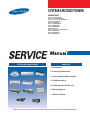
SYSTEM AIRCONDITIONER
INDOOR UNIT
AM007/009/012FN1DCH/AA
AM009/012/018/020FNNDCH/AA
AM009/018/024/030/036/048FN4DCH/AA
AM007/009/012FNLDCH/AA
AM018/024FNLDCH/AA
AM030/036/048FNLDCH/AA
AM018/024FNMDCH/AA
AM030/036FNMDCH/AA
AM048FNMDCH/AA
AM007/009/012/018/020/024FNTDCH/AA
AM036/048FNHDCH/AA
AM076/096FNHDCH/AA
AM018/024FNCDCH/AA
SYSTEM AIRCONDITIONER
CONTENTS
1. Precautions
2. Product Specifications
3. Disassembly and Reassembly
4. Troubleshooting
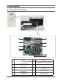
5. PCB Diagram and Parts List
6. Wiring Diagram
7. Reference Sheet
Refer to the service manual in the GSPN(see the rear cover) for the more information.
Section 0
Contents
1. Precautions ..................................................................................................................................................1-1
1-1 Precautions for the Service.............................................................................................................................................................................1-1
1-2 Precautions for the Static Electricity and PL .........................................................................................................................................1-1
1-3 Precautions for the Safety ...............................................................................................................................................................................1-1
1-4 Precautions for Handling Refrigerant for Air Conditioner............................................................................................................1-2
1-5 Precautions for Welding the Air Conditioner Pipe............................................................................................................................1-2
1-6 Precautions for Additional Supplement of Air Conditioner Refrigerant .............................................................................1-2
1-7 Other Precautions ................................................................................................................................................................................................1-2
2. Product Specifications ...............................................................................................................2-1
2-1 Product Specifacations .....................................................................................................................................................................................2-1
2-1-1 Indoor Unit ..............................................................................................................................................................................................2-1
2-2 Accessory and Option Specifications....................................................................................................................................................2-27
2-2-1 Accessories ...........................................................................................................................................................................................2-27
3. Disassembly and Reassembly..................................................................................................3-1
3-1 Indoor Unit ...............................................................................................................................................................................................................3-2
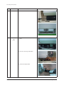
Ŷ Slim 1 way cassette type..........................................................................................................................................................................3-2
Ŷ BIG DUCT ..........................................................................................................................................................................................................3-8
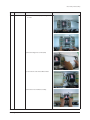
Ŷ Global 4way Cassette type..................................................................................................................................................................3-11
Ŷ Duct type(Slim1,2)....................................................................................................................................................................................3-17
Ŷ Duct type(Slim3)........................................................................................................................................................................................3-22
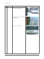
Ŷ Duct type(Mid pressure1......................................................................................................................................................................3-29
Ŷ Duct type(Mid pressure2) ....................................................................................................................................................................3-34
Ŷ CEILING............................................................................................................................................................................................................3-39
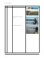
Ŷ Wall mounted type (Neo forte).........................................................................................................................................................3-48
Ŷ Global Mini 4way ......................................................................................................................................................................................3-51
4. Troubleshooting..........................................................................................................................4-1
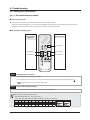
4-1 Check-up Window Description......................................................................................................................................................................4-1
4-2 Service Operation...................................................................................................................................................................................................4-2
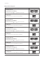
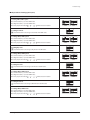
4-2-1 Special Operation ................................................................................................................................................................................4-2
4-3 Troubleshooting......................................................................................................................................................................................................4-7
4-3-1 Setting Option Setup Method.....................................................................................................................................................4-7
4-3-2 Option Items........................................................................................................................................................................................4-13
4-3-3 What to check before diagnosis ..............................................................................................................................................4-16
4-3-4 Number Display Method (Outdoor Unit, MCU, Cable remote control, wall-mount, etc.) ....................4-23
4-4 Appropriate Measures for Different Symptom..................................................................................................................................4-28
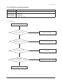
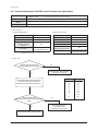
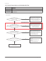
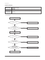
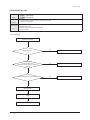
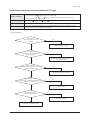
4-4-1 Outdoor Unit Operation Flow...................................................................................................................................................4-28
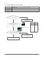
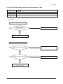
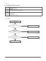
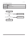
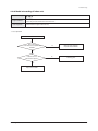
4-4-2 Main PCB has no power phenomenon ..............................................................................................................................4-29
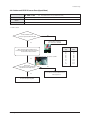
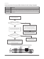
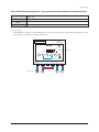
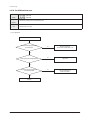
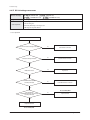
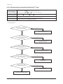
4-4-3 Indoor Unit ROOM sensor Error (Open/Short)................................................................................................................4-30
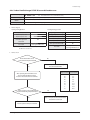
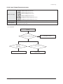
4-4-4 Indoor unit EVAP IN sensor Error (Open/Short)..............................................................................................................4-31
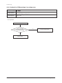
4-4-5 Indoor EVAP OUT sensor Error (Open/Short) ..................................................................................................................4-32
4-4-6 Indoor Heat Exchanger's EVAP IN sensor dislocation error.....................................................................................4-33
4-4-7 Indoor Heat Exchanger's EVA OUT sensor dislocation error (Open/Short) ...................................................4-34
4-4-8 Simultaneous Indoor Heat Exchanger's EVA IN, OUT sensor dislocation error (Open/Short)............4-35
4-4-9 Electronic Expansion Valve opening malfunction (2nd stage) - E135 ..............................................................4-36
4-4-10 Breakdown of EEV (2nd) ..............................................................................................................................................................4-37
4-4-11 Problem with EEV closure (2nd)..............................................................................................................................................4-38
4-4-12 E153 : Detection of Floating Switch of Indoor Unit's Drain Pump ...................................................................4-39
4-4-13 The operational error of Indoor Unit's Fan Motor ......................................................................................................4-40
4-4-14 Mixed operation Error (Only applicable to Heat Pump Model/Not to HR model).................................4-41
Samsung Electronics
1
Section 0
Contents
4-4-15 EEPROM error...................................................................................................................................................................................4-42
4-4-16 Option error of the Remote Controller for an Indoor Unit....................................................................................4-43
4-4-17 Error due to confused use of Fahrenheit and Celsius ..............................................................................................4-43
4-4-18 Simultaneous opening of Cooling/heating MCU SOL Valves 1st/2nd ............................................................4-44
4-4-19 Error due to incorrect Indoor Unit Power/Communication Cable Connection.......................................4-45
4-4-20 SPI Feedback Error.........................................................................................................................................................................4-46
4-4-21 Outdoor Unit Pipe Inspection Error ....................................................................................................................................4-47
4-4-22 Communication Error between Indoor and Outdoor Units during Tracking ...........................................5-48
4-4-23 Communication Error between Indoor and Outdoor Units after Tracking................................................4-49
4-4-24 Communication error between main and sub Unit of outdoor unit or between outdoor units .4-50
4-4-25 Communication Error between MCU and Outdoor Unit......................................................................................4-51
4-4-26 Internal Communication error of the Outdoor Unit C-Box ..................................................................................4-52
4-4-27 Internal PCB Communication error of the Outdoor Unit C-Box........................................................................4-53
4-4-28 Communication Error between MCU and Outdoor Unit after Tracking is Completed.......................4-54
4-4-29 MCU branch part setup error – inconsecutive connection with the use of 2 branch parts.............4-55
4-4-30 MCU branch part setup error – Repeated setup for the same address over 3 times...........................4-56
4-4-31 MCU branch part setup error – non-installed address setup..............................................................................4-57
4-4-32 Setup Error for MCU Branch part – Setup Error for MCU Quantity Used .....................................................4-58
4-4-33 MCU branch part setup error – Overlapping Indoor unit Address setup ...................................................4-59
4-4-34 MCU branch part setup error – Set as being used without connection to an Indoor unit...............4-60
4-4-35 MCU branch part setup error – Connect an Indoor unit to a branch part not being used..............4-61
4-4-36 MCU branch part setup error – Connect more Indoor units than what is actually set up in MCU .....4-62
4-4-37 Outdoor Temperature Sensor Error ....................................................................................................................................4-63
4-4-38 Outdoor Temperature dislocation error...........................................................................................................................4-64
4-4-39 Cond Out Temperature Sensor Error (Open/Short) ..................................................................................................4-65
4-4-40 Outdoor Cond Out sensor breakaway error .................................................................................................................4-66
4-4-41 Digital Compressor Discharge Temperature Sensor Error (OPEN/SHORT).................................................4-67
4-4-42 Constant Rate Compressor Discharge Temperature Sensor Error (OPEN/SHORT)................................4-68
4-4-43 Compressor Discharge or Top 1/2 Temperature sensor error.............................................................................4-69
4-4-44 E265 : Dislocation error of Compressor SUMP Temperature (oil temperature) Sensor......................4-70
4-4-45 E269 : Suction Temperature sensor breakaway error .............................................................................................4-71
4-4-46 SUMP Temperature Sensor Error (OPEN/SHORT) ......................................................................................................4-72
4-4-47 High Pressure sensor error (Open/Short) ........................................................................................................................4-73
4-4-48 Low Pressure sensor error (Open/Short)..........................................................................................................................4-74
4-4-49 Suction Temperature sensor error (Open/Short)........................................................................................................4-75
4-4-50 Liquid Pipe Temperature sensor error (Open/Short)................................................................................................4-76
4-4-51 EVI In Temperature sensor error (Open/Short).............................................................................................................4-77
4-4-52 EVI Out Temperature sensor error (Open/Short) ........................................................................................................4-78
4-4-53 Suction-2 Temperature Sensor Error (OPEN/SHORT)...............................................................................................4-79
4-4-54 E407 : Comp. Down due to High Pressure Protection Control...........................................................................4-80
4-4-55 E410 : Comp. Down due to Low Pressure Protection Control ............................................................................4-81
4-4-56 Sump Sensor Error Due to Protection Control.............................................................................................................4-82
4-4-57 E416 : Comp. Down due to Compressor Discharge Temperature sensor ...................................................4-83
4-4-58 3-phase Input Wiring error.......................................................................................................................................................4-84
4-4-59 E428 : Comp. Down by Compression Ratio Control.................................................................................................4-85
4-4-60 EVI EEV Open error........................................................................................................................................................................4-86
4-4-61 Refrigerant Leakage Error .........................................................................................................................................................4-87
4-4-62 E440, E442 : Prohibition of the operation of Compressor due to Ooutdoor Temperature..............4-88
4-4-63 High Pressure Standard Not Met before Air Conditioning (Inability to Re-operate) ............................4-89
4-4-64 CCH Malfunction and Sump Sensor Miswiring Error...............................................................................................4-90
4-4-65 Fan starting error............................................................................................................................................................................4-91
4-4-66 Fan lock error ....................................................................................................................................................................................4-92
4-4-67 Momentary Blackout error.......................................................................................................................................................4-93
4-4-68 Outdoor Fan Motor overheating..........................................................................................................................................4-94
4-4-69 Outdoor Unit Fan Motor RPM Error ....................................................................................................................................4-95
4-4-70 Fan IPM Overheat error ..............................................................................................................................................................4-96
4-4-71 Over-Voltage Error of an Outdoor Fan Motor...............................................................................................................4-97
4-4-72 Counter-Rotation Error of an Outdoor Fan Motor .....................................................................................................4-97
2
Samsung Electronics
Section 0
Contents
4-4-73 E458 : Compressor Excess Current Error ..........................................................................................................................4-98
4-4-74 Compressor starting error ........................................................................................................................................................4-99
4-4-75 Inverter Overcurrent error ......................................................................................................................................................4-100
4-4-76 Overvoltage / Low voltage error ........................................................................................................................................4-101
4-4-77 DC Link voltage sensor error.................................................................................................................................................4-102
4-4-78 Liquid Compression Prevention Control .......................................................................................................................4-103
4-4-79 Fan Motor Overcurrent error.................................................................................................................................................4-104
4-4-80 Input / Output Current sensor error .................................................................................................................................4-105
4-4-81 Outdoor Fan PCB Overvoltage / Low voltage error................................................................................................4-106
4-4-82 Hall IC(Fan) error ...........................................................................................................................................................................4-107
4-4-83 Inverter Overheat error ............................................................................................................................................................4-108
4-4-84 Model mismatching of Indoor unit. .................................................................................................................................4-109
4-4-85 Breakdown of an EEV(1st)........................................................................................................................................................4-110
4-4-86 Breakdown of an EEV closure...............................................................................................................................................4-111
4-4-87 Electronic expansion valve closing malfunction (2nd stage) .............................................................................4-112
4-4-88 Electronic expansion valve opening malfunction (2nd stage)..........................................................................4-113
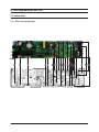
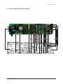
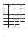
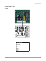
5. PCB Diagram and Parts List ......................................................................................................5-1
5-1Indoor Unit...............................................................................................................................................................................................................5-1
5-1-1Slim 1 way cassette type ..................................................................................................................................................................5-1
5-1-2 4way cassette , mini 4way casette type .................................................................................................................................5-3
5-1-3 Duct type (SLIM 1,2)...........................................................................................................................................................................5-5
5-1-4 Duct type (Slim Duct 3)....................................................................................................................................................................5-8
5-1-5 Duct type(MSP)..................................................................................................................................................................................5-11
5-1-6 Duct type (Super) .............................................................................................................................................................................5-13
5-1-7 Celing type............................................................................................................................................................................................5-15
5-1-8 Wall-Mounted type (Neo Forte)...............................................................................................................................................5-17
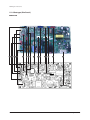
6. Wiring Diagram ...........................................................................................................................6-1
6-1 Indoor ........................................................................................................................................................................................................................6-1
6-1-1 Global 4way(Global Mini-4way) cassteet type...................................................................................................................6-1
6-1-2 Slim 1way cassette type ..................................................................................................................................................................6-2
6-1-3 BIG Duct ....................................................................................................................................................................................................6-3
6-1-4 Ceiling.........................................................................................................................................................................................................6-4
6-1-5 RAC(Neo Forte) .....................................................................................................................................................................................6-5
6-1-6 DUCT type (Slim III).............................................................................................................................................................................6-6
6-1-7 DUCT type (Slim I, II, MSP) ..............................................................................................................................................................6-7
7. Reference Sheet ..........................................................................................................................7-1
7-1 Index for Model Name.....................................................................................................................................................................................7-1
7-1-1 Indoor Unit ..............................................................................................................................................................................................7-1
7-1-2 Panel ............................................................................................................................................................................................................7-2
7-2 Pump-down Method .......................................................................................................................................................................................7-3
7-2-1 Precautions for Pump-down ........................................................................................................................................................7-3
7-2-2 For Single Installation of Outdoor Unit (Only One Outdoor Unit Installed) .....................................................7-3
7-2-3 When Two or More Outdoor Units are Installed ...............................................................................................................7-3
7-3 How to Put Refrigerant in Refrigerant Container ............................................................................................................................7-4
7-3-1 How to put refrigerant in container before pump-down...........................................................................................7-4
Samsung Electronics
3
1. Precautions
1-1 Precautions for the Service
OUse the correct parts when changing the electric parts.
– Please check the labels and notices for the model name, proper voltage, and proper current for the electric parts.
OFully repair the connection for the types of harness when repairing the product after breakdown.
– A faulty connection can cause irregular noise and problems.
OWhen disassembling or assembling, make sure that the product is laid down on a work cloth.
– Doing so will prevent scratching to the exterior of the rear side of the product.
OCompletely remove dust or foreign substances on the housing, connection, and inspection parts when performing repairs.
– This can prevent fire hazards for tracking, short, etc.
OPlease tighten the service valve of the outdoor unit and the valve cap of the charging valve as securely as possible by using
a monkey spanner.
OCheck whether the parts are properly and securely assembled after performing repairs.
– These parts should be in the same condition as before the repair.
1-2 Precautions for the Static Electricity and PL
OPlease carefully handle the PCB power terminal during repair and measurement when it is turned on since it is vulnerable
to static electricity.
– Please wear insulation gloves before performing PCB repair and measurement.
OCheck if the place of installation is at least 2m away from electronic appliances such as TV, video players, and stereos.
– This can cause irregular noise or degrade the picture quality.
OPlease make sure the customer does not directly repair the product.
– Arbitrary dismantling may result in electric shock or fire.
1-3 Precautions for the Safety
ODo not pull or touch the power plug or the subsidiary power switch with wet hands.
– This may result in electric shock or fire.
OIf the power line or the power plug is damaged, then it must be changed since this is a hazard.
ODo not bend the wire too much or position it so that it can be damaged by a heavy object on top.
– This may result in electric shock or fire.
OThe use of multiple electric outlets should be prohibited.
– This may result in electric shock or fire.
OGround the connection if it is necessary.
– The connection must be grounded if there is any risk of electrical short due to water or moisture.
OUnplug the power or turn off the subsidiary power switch when changing or repairing electrical parts.
– Doing so will prevent electric shock.
OExplain to workers that the battery for the remote control needs to be separated for storage purposes when the product
will not be used for a long time.
– This can cause a problem for the remote control since battery fluid may trickle out.
Samsung Electronics
1-1
1-4 Precautions for Handling Refrigerant for Air Conditioner
Environmental Cautions: Air pollution due to gas release
OSafety Cautions
If liquid gas is released, then body parts that come into contact with it may experience frostbite/blister/numbness.
If a large amount of gas is released, then suffocation may occur due to lack of oxygen. If the released gas is heated, then noxious
gas may be produced by combustion.
OContainer Handling Cautions
Do not subject container to physical shock or overheating. (Flowage is possible while moving within the regulated pressure.)
1-5 Precautions for Welding the Air Conditioner Pipe
ODangerous or flammable objects around the pipe must be removed before the welding.
OIf the refrigerant is kept inside the product or the pipe, then remove the refrigerant prior to welding.
If the welding is carried out while the refrigerant is kept inside, the welding cannot be properly performed. This will also produce
noxious gas that is a health hazard. This leakage will also explode with the refrigerant and oil due to an increase in the refrigerant
pressure, posing a danger to workers.
OPlease remove the oxide produced inside the pipe during the welding with nitrogen gas.
Using another gas may cause harm to the product or others.
1-6 Precautions for Additional Supplement of Air Conditioner Refrigerant
OPrecisely calculate the refrigerant by using a scale and S-net, and proceed with the test operation.
Excessive supplement can cause harm to the product since it can cause an inflow of the liquid refrigerant into the compressor.
ODo not heat the refrigerant container for a forced injection.
This may cause harm to the product or others since the refrigerant container may burst.
ODo not operate the product after removing the product safety pressure switch and sensor.
If the product is blocked inside, then this may cause harm to the product or others due to the excess pressure increase of the
refrigerant gas.
1-7 Other Precautions
OThere should be no leakage of the pipes after installation. When withdrawing the refrigerant, the compressor should be
stopped before removing the connecting pipe.
If the compressor is operating while the refrigerant pipe is not correctly connected and the service valve is opened, then
air and other substances can enter the pipe. The interior of the refrigerant cycle may then build up excessive high pressure
resulting in explosion and damage.
1-2
Samsung Electronics
2. Product Specifications
2-1 Product Specifacations
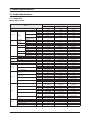
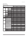
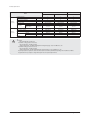
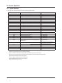
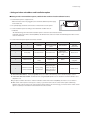
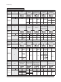
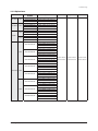
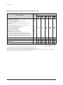
2-1-1 Indoor Unit
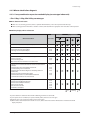
QSlim 1WAY cassette
JSF-1
Model
Power Supply
Mode
Cooling 2)
Performance
Power
Capacity
(Nominal)
Heating 2)
Power Input
(Nominal)
Condensate
(with high fan speed)
Cooling 1)
Heating 2)
Cooling 1)
Heating 2)
Current Input
(Nominal)
Type
Motor
Fan
Air Flow Rate
External Pressure
Sound Pressure
Sound Power
Type
Refrigerant
Control Method
Temperature Control
Safety devices
Sound
Model
Type
Output x n
H/M/L
Min / Std / Max
High / Mid / Low
High / Mid / Low
Liquid Pipe (Flare)
Piping
Connections
Gas Pipe (Flare)
Drain Pipe (Quick lock)
Net Weight
Shipping Weight
Dimensions
Net Dimensions (W×H×D)
Shipping Dimensions (W×H×D)
Panel model
Panel Net Weight
Panel Size
Shipping Weight
Net Dimensions (W×H×D)
Shipping Dimensions (W×H×D)
Functions
AM007FN1DCH/AA
AM009FN1DCH/AA
AM012FN1DCH/AA
1,2,208-230,60
HP/HR
1,2,208-230,60
HP/HR
1,2,208-230,60
HP/HR
7,500
9,500
12,000
8,500
10,500
13,500
40
40
0.23
0.23
Crossflow fan
Y4S476B041L
BLDC
20 x 1
7.00 / 6.00 / 5.00
45
45
0.25
0.25
Crossflow Fan
Y4S476B041L
BLDC
20 x 1
7.00 / 6.00 / 5.00
50
50
0.28
0.28
Crossflow Fan
Y4S476B041L
BLDC
20 x 1
8.00 / 7.00 / 6.00
29.0 / - / 27.0
R-410A
EEV INCLUDED
Micom&Thermistors
Fuse
6.35
1/4"
12.7
1/2"
VP 20 (ODø26,IDø20)
16
35.3
18
39.7
970 x 135 x 410
38.2 x 5.3 x 16.1
1,164 x 212 x 478
45.8 x 8.3 x 18.8
30.0 / - / 27.0
35.0 / - / 30.0
R-410A
EEV INCLUDED
Micom&Thermistors
Fuse
6.35
1/4"
12.7
1/2"
VP20 (OD 26,ID 20)
16
35.3
18
39.7
970 x 135 x 410
38.2 x 5.3 x 16.1
1,164 x 212 x 478
45.8 x 8.3 x 18.8
R-410A
EEV INCLUDED
Micom&Thermistors
Fuse
6.35
1/4"
12.7
1/2"
VP20 (OD 26,ID 20)
16
35.3
18
39.7
970 x 135 x 410
38.2 x 5.3 x 16.1
1,164 x 212 x 478
45.8 x 8.3 x 18.8
-
"PC1NUSMAN
PC1NUPMAN"
"PC1NUSMAN
PC1NUPMAN"
"PC1NUSMAN
PC1NUPMAN"
kg
lbs
kg
lbs
mm
3.1
6.8
4.5
9.9
1,180 x 25 x 460
3.1
6.8
4.5
9.9
1,180 x 25 x 460
3.1
6.8
4.5
9.9
1,180 x 25 x 460
ø, #, V, Hz
-
Auto restart
Auto swing
Group/individual control
External contact control
Trouble shooting by LED
Samsung Electronics
kW
Btu/h
kW
Btu/h
Liter/h
W
A
W
CMM
Pa
WG
dBA
ø,mm
ø, inch
ø,mm
ø, inch
ø,mm
kg
lbs
kg
lbs
mm
inch
mm
inch
inches
46.5 x 1 x 18.1
46.5 x 1 x 18.1
46.5 x 1 x 18.1
mm
inch
-
1,259 x 144 x 539
49.6 x 5.7 x 21.2
O
O
O
O
O
1,259 x 144 x 539
49.6 x 5.7 x 21.2
O
O
O
O
O
1,259 x 144 x 539
49.6 x 5.7 x 21.2
O
O
O
O
O
2-1
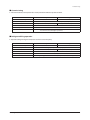
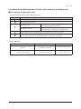
Product Specifications
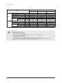
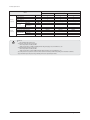
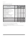
JSF-1
Model
Standard
accessories
Installation manual
Operation manual
Pattern sheet for installation
Flexible drain hose
Flilter/Safety grille
Drain pump
Drain pump
Optional
accessories
Max. lifting Height /
Displacement
Wireless remote controller
wired remote controller
External contact interface module
Receiver
Duct Receiver kits
Receiver wire
EEV kits
AM007FN1DCH/AA
AM009FN1DCH/AA
AM012FN1DCH/AA
- / O
X
O
O
Filter (washable)
-
O
X
O
O
Filter (washable)
-
O
X
O
O
Filter (washable)
-
mm / liter/h
750 / 24
750 / 24
750 / 24
-
MR-DH00
MWR-WE10N
MIM-B14
MR-DH00
MWR-WE10N
MIM-B14
MR-DH00
MWR-WE10N
MIM-B14
*1) Mode
- HP : Heat Pump, HR : Heat Recovery
*2) Nominal cooling capacities are based on;
- Indoor temperature : 27˚C DB, 19˚C WB
- Outdoor temperature : 35˚C DB, 24˚C WB, Equivalent refrigerant piping : 7.5m, Level differences : 0m
*3) Nominal heating capacities are based on;
- Indoor temperature : 20˚C DB, 15˚C WB
- Outdoor temperature : 7˚C DB, 6˚C WB, Equivalent refrigerant piping : 7.5m, Level differences : 0m
*4) Sound pressure was acquired in a dead room. Thus actual noise level may be different depending on the installation conditions.
*5) Specifications may be subject to change without prior notice for product improvement.
2-2
Samsung Electronics
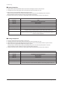
Product Specifications
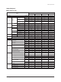
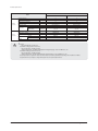
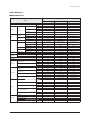
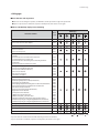
Indoor Unit(cont.)
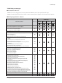
QMini 4WAY cassette
Small
Model
Power Supply
Mode
Cooling 2)
Performance
Power
Capacity
(Nominal)
Heating 2)
Power Input
(Nominal)
Condensate
(with high fan speed)
Cooling 1)
Heating 2)
Cooling 1)
Heating 2)
Current Input
(Nominal)
Type
Motor
Fan
Air Flow Rate
External Pressure
Sound Pressure
Sound Power
Type
Refrigerant
Control Method
Temperature Control
Safety devices
Sound
Model
Type
Output x n
H/M/L
Min / Std / Max
High / Mid / Low
High / Mid / Low
Liquid Pipe (Flare)
Piping
Connections
Gas Pipe (Flare)
Drain Pipe (Quick lock)
Net Weight
Shipping Weight
Dimensions
Net Dimensions (W×H×D)
Shipping Dimensions (W×H×D)
Panel model
Panel Net Weight
Panel Size
Shipping Weight
Net Dimensions (W×H×D)
Shipping Dimensions (W×H×D)
Functions
Auto restart
Auto swing
Group/individual control
External contact control
Trouble shooting by LED
Samsung Electronics
AM018FNNDCH/AA AM020FNNDCH/AA
AM009FNNDCH/AA
AM012FNNDCH/AA
1,2,208-230,60
HP/HR
1,2,208-230,60
HP/HR
1,2,208-230,60
HP/HR
1,2,208-230,60
HP/HR
9,500
12,000
18,000
20,000
10,500
13,500
20,000
23,000
ø,mm
ø, inch
ø,mm
ø, inch
ø,mm
kg
lbs
kg
lbs
mm
inch
mm
inch
24
24
0.17
0.17
Turbo Fan
FMC6531SSJ
BLDC
65 x 1
10.00 / 8.50 / 7.50
34.0 / 30.0 / 26.0
R-410A
EEV INCLUDED
Micom&Thermistors
Fuse
6.35
1/4"
12.7
1/2"
VP25 (OD 32,ID 25)
12
26.5
14
30.9
575 x 250 x 575
22.6 x 9.8 x 22.6
623 x 298 x 653
24.5 x 11.7 x 25.7
28
28
0.19
0.19
Turbo Fan
FMC6531SSJ
BLDC
65 x 1
10.50 / 9.50 / 8.00
36.0 / 34.0 / 31.0
R-410A
EEV INCLUDED
Micom&Thermistors
Fuse
6.35
1/4"
12.7
1/2"
VP25 (OD 32,ID 25)
12
26.5
14
30.9
575 x 250 x 575
22.6 x 9.8 x 22.6
623 x 298 x 653
24.5 x 11.7 x 25.7
36
36
0.27
0.27
Turbo Fan
FMC6531SSJ
BLDC
65 x 1
13.00 / 11.00 / 9.50
40.0 / 37.0 / 34.0
R-410A
EEV INCLUDED
Micom&Thermistors
Fuse
6.35
1/4"
12.7
1/2"
VP25 (OD 32,ID 25)
12
26.5
14
30.9
575 x 250 x 575
22.6 x 9.8 x 22.6
623 x 298 x 653
24.5 x 11.7 x 25.7
38
38
0.3
0.3
Turbo Fan
FMC6531SSJ
BLDC
65 x 1
13.50 / 12.00 / 10.20
41.0 / 37.0 / 34.0
R-410A
EEV INCLUDED
Micom&Thermistors
Fuse
6.35
1/4"
12.7
1/2"
VP25 (OD 32,ID 25)
12
26.5
14
30.9
575 x 250 x 575
22.6 x 9.8 x 22.6
623 x 298 x 653
24.5 x 11.7 x 25.7
-
PC4SUSMAN
PC4SUSMAN
PC4SUSMAN
PC4SUSMAN
kg
lbs
kg
lbs
mm
2.7
6
4.2
9.3
670 x 45 x 670
2.7
6
4.2
9.3
670 x 45 x 670
2.7
6
4.2
9.3
670 x 45 x 670
2.7
6
4.2
9.3
670 x 45 x 670
inches
26.4 x 1.8 x 26.4
26.4 x 1.8 x 26.4
26.4 x 1.8 x 26.4
26.4 x 1.8 x 26.4
mm
inch
-
714 x 106 x 724
28.1 x 4.2 x 28.5
O
O
O
O
O
714 x 106 x 724
28.1 x 4.2 x 28.5
O
O
O
O
O
714 x 106 x 724
28.1 x 4.2 x 28.5
O
O
O
O
O
714 x 106 x 724
28.1 x 4.2 x 28.5
O
O
O
O
O
ø, #, V, Hz
kW
Btu/h
kW
Btu/h
Liter/h
W
A
W
CMM
Pa
WG
dBA
2-3
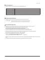
Product Specifications
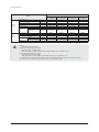
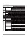
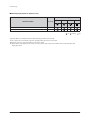
Small
Model
Standard
accessories
Installation manual
Operation manual
Pattern sheet for installation
Flexible drain hose
Flilter/Safety grille
Drain pump
Drain pump
Optional
accessories
Max. lifting Height /
Displacement
Wireless remote controller
wired remote controller
External contact interface module
Receiver
Duct Receiver kits
Receiver wire
EEV kits
AM018FNNDCH/AA AM020FNNDCH/AA
AM009FNNDCH/AA
AM012FNNDCH/AA
- / O
X
O
O
Filter / Safety grille
-
O
X
O
O
Filter / Safety grille
-
O
X
O
O
Filter / Safety grille
-
O
X
O
O
Filter / Safety grille
-
mm / liter/h
750 / 24
750 / 24
750 / 24
750 / 24
-
AR-DH00
MWR-WE10N
MIM-B14
AR-DH00
MWR-WE10N
MIM-B14
AR-DH00
MWR-WE10N
MIM-B14
AR-DH00
MWR-WE10N
MIM-B14
*1) Mode
- HP : Heat Pump, HR : Heat Recovery
*2) Nominal cooling capacities are based on;
- Indoor temperature : 27˚C DB, 19˚C WB
- Outdoor temperature : 35˚C DB, 24˚C WB, Equivalent refrigerant piping : 7.5m, Level differences : 0m
*3) Nominal heating capacities are based on;
- Indoor temperature : 20˚C DB, 15˚C WB
- Outdoor temperature : 7˚C DB, 6˚C WB, Equivalent refrigerant piping : 7.5m, Level differences : 0m
*4) Sound pressure was acquired in a dead room. Thus actual noise level may be different depending on the installation conditions.
*5) Specifications may be subject to change without prior notice for product improvement.
2-4
Samsung Electronics
Product Specifications
Indoor Unit(cont.)
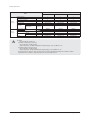
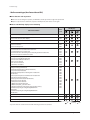
Q4WAY casette (Small)
4WAY casette - Small
Model
Power Supply
Mode
Cooling 2)
Performance
Power
Capacity
(Nominal)
Heating 2)
Power Input
(Nominal)
Condensate
(with high fan speed)
Cooling 1)
Heating 2)
Cooling 1)
Heating 2)
Current Input
(Nominal)
Type
Motor
Fan
Air Flow Rate
External Pressure
Sound Pressure
Sound Power
Type
Refrigerant
Control Method
Temperature Control
Safety devices
Sound
Model
Type
Output x n
H/M/L
Min / Std / Max
High / Mid / Low
High / Mid / Low
Liquid Pipe (Flare)
Piping
Connections
Gas Pipe (Flare)
Drain Pipe (Quick lock)
Net Weight
Shipping Weight
Dimensions
Net Dimensions (W×H×D)
Shipping Dimensions (W×H×D)
Panel model
Panel Net Weight
Panel Size
Shipping Weight
Net Dimensions (W×H×D)
Shipping Dimensions (W×H×D)
Functions
AM009FN4DCH/AA
AM018FN4DCH/AA
AM024FN4DCH/AA
1,2,208-230,60
HP/HR
1,2,208-230,60
HP/HR
1,2,208-230,60
HP/HR
9,000
18,000
24,000
10,000
20,000
27,000
ø,mm
ø, inch
ø,mm
ø, inch
ø,mm
kg
lbs
kg
lbs
mm
inch
mm
inch
28
28
0.2
0.2
Turbo Fan
FMC6531SSH
BLDC
65 x 1
14.50/13.00/11.00
R-410A
EEV INCLUDED
Micom&Thermistors
Fuse
6.35
1/4"
12.7
1/2"
VP25 (OD32,ID25)
25
55.1
31
68.3
840 x 218 x 840
33.1 x 8.6 x 33.1
925 x 280 x 925
36.4 x 11 x 36.4
32
32
0.25
0.25
Turbo Fan
FMC6531SSH
BLDC
65 x 1
15.50 / 14.00 / 12.00
R-410A
EEV INCLUDED
Micom&Thermistors
Fuse
6.35
1/4"
12.7
1/2"
VP25 (OD32,ID25)
25
55.1
31
68.3
840 x 218 x 840
33.1 x 8.6 x 33.1
925 x 280 x 925
36.4 x 11 x 36.4
40
40
0.3
0.3
Turbo Fan
FMC6531SSH
BLDC
65 x 1
17.50 / 16.00 / 14.00
R-410A
EEV INCLUDED
Micom&Thermistors
Fuse
6.35
1/4"
12.7
1/2"
VP25 (OD32,ID25)
25
55.1
31
68.3
840 x 218 x 840
33.1 x 8.6 x 33.1
925 x 280 x 925
36.4 x 11 x 36.4
-
PC4NUSKAN
PC4NUSKAN
PC4NUSKAN
kg
lbs
kg
lbs
mm
7
15.4
10.3
22.7
950 x 35 x 950
7
15.4
10.3
22.7
950 x 35 x 950
7
15.4
10.3
22.7
950 x 35 x 950
ø, #, V, Hz
-
Auto restart
Auto swing
Group/individual control
External contact control
Trouble shooting by LED
Samsung Electronics
kW
Btu/h
kW
Btu/h
Liter/h
W
A
W
CMM
Pa
WG
dBA
inches
37.4 x 1.4 x 37.4
37.4 x 1.4 x 37.4
37.4 x 1.4 x 37.4
mm
inch
-
1042 x 103 x 1042
41 x 4.1 x 41
O
O
O
O
O
1042 x 103 x 1042
41 x 4.1 x 41
O
O
O
O
O
1042 x 103 x 1042
41 x 4.1 x 41
O
O
O
O
O
2-5
Product Specifications
4WAY casette - Small
Model
Standard
accessories
Installation manual
Operation manual
Pattern sheet for installation
Flexible drain hose
Flilter/Safety grille
Drain pump
Drain pump
Optional
accessories
Max. lifting Height /
Displacement
Wireless remote controller
wired remote controller
External contact interface module
Receiver
Duct Receiver kits
Receiver wire
EEV kits
AM009FN4DCH/AA
AM018FN4DCH/AA
AM024FN4DCH/AA
- / O
X
O
O
Filter / Safety grille
-
O
X
O
O
Filter / Safety grille
-
O
X
O
O
Filter / Safety grille
-
mm / liter/h
750 / 24
750 / 24
750 / 24
-
AR-DH00
MWR-WE10N
MIM-B14
AR-DH00
MWR-WE10N
MIM-B14
AR-DH00
MWR-WE10N
MIM-B14
*1) Mode
- HP : Heat Pump, HR : Heat Recovery
*2) Nominal cooling capacities are based on;
- Indoor temperature : 27˚C DB, 19˚C WB
- Outdoor temperature : 35˚C DB, 24˚C WB, Equivalent refrigerant piping : 7.5m, Level differences : 0m
*3) Nominal heating capacities are based on;
- Indoor temperature : 20˚C DB, 15˚C WB
- Outdoor temperature : 7˚C DB, 6˚C WB, Equivalent refrigerant piping : 7.5m, Level differences : 0m
*4) Sound pressure was acquired in a dead room. Thus actual noise level may be different depending on the installation conditions.
*5) Specifications may be subject to change without prior notice for product improvement.
2-6
Samsung Electronics
Product Specifications
Indoor Unit(cont.)
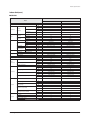
Q4WAY casette (Large)
4WAY casette - Large
Model
Power Supply
Mode
Cooling 2)
Performance
Power
Capacity
(Nominal)
Heating 2)
Power Input
(Nominal)
Condensate
(with high fan speed)
Cooling 1)
Heating 2)
Cooling 1)
Heating 2)
Current Input
(Nominal)
Type
Motor
Fan
Air Flow Rate
External Pressure
Sound Pressure
Sound Power
Type
Refrigerant
Control Method
Temperature Control
Safety devices
Sound
Model
Type
Output x n
H/M/L
Min / Std / Max
High / Mid / Low
High / Mid / Low
Liquid Pipe (Flare)
Piping
Connections
Gas Pipe (Flare)
Drain Pipe (Quick lock)
Net Weight
Shipping Weight
Dimensions
Net Dimensions (W×H×D)
Shipping Dimensions (W×H×D)
Panel model
Panel Net Weight
Panel Size
Shipping Weight
Net Dimensions (W×H×D)
Shipping Dimensions (W×H×D)
Functions
AM030FN4DCH/AA
AM036FN4DCH/AA
AM048FN4DCH/AA
1,2,208-230,60
HP/HR
1,2,208-230,60
HP/HR
1,2,208-230,60
HP/HR
30,000
36,000
48,000
34,000
40,000
54,000
ø,mm
ø, inch
ø,mm
ø, inch
ø,mm
kg
lbs
kg
lbs
mm
inch
mm
inch
65
65
0.5
0.5
Turbo Fan
FMC6531SSH
BLDC
65 x 1
22.00 / 19.50 / 17.00
R-410A
EEV INCLUDED
Micom&Thermistors
Fuse
9.52
3/8"
15.88
5/8"
VP25 (OD32,ID25)
29
63.9
35
77.2
840 x 298 x 840
33.1 x 11.7 x 33.1
925 x 360 x 925
36.4 x 14.2 x 36.4
75
75
0.56
0.56
Turbo Fan
FMC6531SSH
BLDC
65 x 1
24.00 / 22.00 / 20.00
R-410A
EEV INCLUDED
Micom&Thermistors
Fuse
9.52
3/8"
15.88
5/8"
VP25 (OD32,ID25)
29
63.9
35
77.2
840 x 298 x 840
33.1 x 11.7 x 33.1
925 x 360 x 925
36.4 x 14.2 x 36.4
95
95
0.75
0.75
Turbo Fan
FMC6531SSH
BLDC
65 x 1
29.00 / 27.00 / 24.00
R-410A
EEV INCLUDED
Micom&Thermistors
Fuse
9.52
3/8"
15.88
5/8"
VP25 (OD32,ID25)
29
63.9
35
77.2
840 x 298 x 840
33.1 x 11.7 x 33.1
925 x 360 x 925
36.4 x 14.2 x 36.4
-
PC4NUSKAN
PC4NUSKAN
PC4NUSKAN
kg
lbs
kg
lbs
mm
7
15.4
10.3
22.7
950 x 35 x 950
7
15.4
10.3
22.7
950 x 35 x 950
7
15.4
10.3
22.7
950 x 35 x 950
ø, #, V, Hz
-
Auto restart
Auto swing
Group/individual control
External contact control
Trouble shooting by LED
Samsung Electronics
kW
Btu/h
kW
Btu/h
Liter/h
W
A
W
CMM
Pa
WG
dBA
inches
37.4 x 1.4 x 37.4
37.4 x 1.4 x 37.4
37.4 x 1.4 x 37.4
mm
inch
-
1042 x 103 x 1042
41 x 4.1 x 41
O
O
O
O
O
1042 x 103 x 1042
41 x 4.1 x 41
O
O
O
O
O
1042 x 103 x 1042
41 x 4.1 x 41
O
O
O
O
O
2-7
Product Specifications
4WAY casette - Large
Model
Standard
accessories
Installation manual
Operation manual
Pattern sheet for installation
Flexible drain hose
Flilter/Safety grille
Drain pump
Drain pump
Optional
accessories
Max. lifting Height /
Displacement
Wireless remote controller
wired remote controller
External contact interface module
Receiver
Duct Receiver kits
Receiver wire
EEV kits
AM030FN4DCH/AA
AM036FN4DCH/AA
AM048FN4DCH/AA
- / O
X
O
O
Filter / Safety grille
-
O
X
O
O
Filter / Safety grille
-
O
X
O
O
Filter / Safety grille
-
mm / liter/h
750 / 24
750 / 24
750 / 24
-
AR-DH00
MWR-WE10N
MIM-B14
AR-DH00
MWR-WE10N
MIM-B14
AR-DH00
MWR-WE10N
MIM-B14
*1) Mode
- HP : Heat Pump, HR : Heat Recovery
*2) Nominal cooling capacities are based on;
- Indoor temperature : 27˚C DB, 19˚C WB
- Outdoor temperature : 35˚C DB, 24˚C WB, Equivalent refrigerant piping : 7.5m, Level differences : 0m
*3) Nominal heating capacities are based on;
- Indoor temperature : 20˚C DB, 15˚C WB
- Outdoor temperature : 7˚C DB, 6˚C WB, Equivalent refrigerant piping : 7.5m, Level differences : 0m
*4) Sound pressure was acquired in a dead room. Thus actual noise level may be different depending on the installation conditions.
*5) Specifications may be subject to change without prior notice for product improvement.
2-8
Samsung Electronics
Product Specifications
Indoor Unit(cont.)
QSLIM DUCT(Slim1)
Slim1
Model
Power Supply
Mode
Power
Capacity
(Nominal)
Heating 2)
Power Input
(Nominal)
Condensate
(with high fan speed)
Cooling 1)
Heating 2)
Cooling 1)
Heating 2)
Current Input
(Nominal)
Type
Motor
Fan
Air Flow Rate
External Pressure
Sound Pressure
Sound Power
Type
Refrigerant
Control Method
Temperature Control
Safety devices
Sound
Model
Type
Output x n
H/M/L
Min / Std / Max
High / Mid / Low
High / Mid / Low
Liquid Pipe (Flare)
Piping
Connections
Gas Pipe (Flare)
Drain Pipe (Quick lock)
Net Weight
Shipping Weight
Dimensions
Net Dimensions (W×H×D)
Shipping Dimensions (W×H×D)
Panel model
Panel Net Weight
Panel Size
Shipping Weight
Net Dimensions (W×H×D)
Shipping Dimensions (W×H×D)
Functions
AM009FNLDCH/AA
AM012FNLDCH/AA
1,2,208-230,60
HP/HR
1,2,208-230,60
HP/HR
1,2,208-230,60
HP/HR
7,500
9,500
12,000
8,500
10,500
13,500
ø,mm
ø, inch
ø,mm
ø, inch
ø,mm
kg
lbs
kg
lbs
mm
inch
mm
inch
47
47
0.32
0.32
Sirocco Fan
YSK110-25-6SN
SSR
40 x 1
8.00 / 7.00 / 6.00
0.00 / 2.00 / 4.00
0.00 / 19.61 / 39.23
31.0 / - / 26.0
R-410A
EEV INCLUDED
Micom&Thermistors
Fuse
6.35
1/4"
12.7
1/2"
VP25 (OD 32,ID 25)
26
57.3
31
68.3
900 x 199 x 600
35.4 x 7.8 x 23.6
1,133 x 330 x 730
44.6 x 13 x 28.7
60
60
0.4
0.4
Sirocco Fan
YSK110-25-6SN
SSR
50 x 1
9.00 / 8.00 / 7.00
0.00 / 2.00 / 4.00
0.00 / 19.61 / 39.23
32.0 / - / 27.0
R-410A
EEV INCLUDED
Micom&Thermistors
Fuse
6.35
1/4"
12.7
1/2"
VP25 (OD 32,ID 25)
26
57.3
31
68.3
900 x 199 x 600
35.4 x 7.8 x 23.6
1,133 x 330 x 730
44.6 x 13 x 28.7
75
75
0.51
0.51
Sirocco Fan
YSK110-25-6SN
SSR
60 x 1
10.00 / 8.50 / 7.00
0.00 / 2.00 / 4.00
0.00 / 19.61 / 39.23
33.0 / - / 30.0
R-410A
EEV INCLUDED
Micom&Thermistors
Fuse
6.35
1/4"
12.7
1/2"
VP25 (OD 32,ID 25)
26
57.3
31
68.3
900 x 199 x 600
35.4 x 7.8 x 23.6
1,133 x 330 x 730
44.6 x 13 x 28.7
-
-
-
-
kg
lbs
kg
lbs
mm
-
-
-
inches
-
-
-
mm
inch
-
O
X
O
O
X
O
X
O
O
X
O
X
O
O
X
ø, #, V, Hz
Cooling 2)
Performance
AM007FNLDCH/AA
Auto restart
Auto swing
Group/individual control
External contact control
Trouble shooting by LED
Samsung Electronics
kW
Btu/h
kW
Btu/h
Liter/h
W
A
W
CMM
Pa
WG
dBA
2-9
Product Specifications
Slim1
Model
Standard
accessories
Installation manual
Operation manual
Pattern sheet for installation
Flexible drain hose
Flilter/Safety grille
Drain pump
Drain pump
Optional
accessories
Max. lifting Height /
Displacement
Wireless remote controller
wired remote controller
External contact interface module
Receiver
Duct Receiver kits
Receiver wire
EEV kits
AM007FNLDCH/AA
AM009FNLDCH/AA
AM012FNLDCH/AA
- / O
O
X
O
Filter (washable)
MDP-E075SEE3D
O
O
X
O
Filter (washable)
MDP-E075SEE3D
O
O
X
O
Filter (washable)
MDP-E075SEE3D
mm / liter/h
750 / 24
750 / 24
750 / 24
-
MR-DH00
MWR-WE10N
MIM-B14
MRK-A10
MRW-10A
MR-DH00
MWR-WE10N
MIM-B14
MRK-A10
MRW-10A
MR-DH00
MWR-WE10N
MIM-B14
MRK-A10
MRW-10A
*1) Mode
- HP : Heat Pump, HR : Heat Recovery
*2) Nominal cooling capacities are based on;
- Indoor temperature : 27˚C DB, 19˚C WB
- Outdoor temperature : 35˚C DB, 24˚C WB, Equivalent refrigerant piping : 7.5m, Level differences : 0m
*3) Nominal heating capacities are based on;
- Indoor temperature : 20˚C DB, 15˚C WB
- Outdoor temperature : 7˚C DB, 6˚C WB, Equivalent refrigerant piping : 7.5m, Level differences : 0m
*4) Sound pressure was acquired in a dead room. Thus actual noise level may be different depending on the installation conditions.
*5) Specifications may be subject to change without prior notice for product improvement.
2-10
Samsung Electronics
Product Specifications
Indoor Unit(cont.)
QSLIM DUCT(Slim2)
Slim2
Model
Power Supply
Mode
Power
Capacity
(Nominal)
Heating 2)
Power Input
(Nominal)
Condensate
(with high fan speed)
Cooling 1)
Heating 2)
Cooling 1)
Heating 2)
Current Input
(Nominal)
Type
Motor
Fan
Air Flow Rate
External Pressure
Sound Pressure
Sound
Sound Power
Type
Refrigerant
Control Method
Temperature Control
Safety devices
Model
Type
Output x n
H/M/L
Min / Std / Max
High / Mid / Low
High / Mid / Low
Liquid Pipe (Flare)
Piping
Connections
Gas Pipe (Flare)
Drain Pipe (Quick lock)
Net Weight
Shipping Weight
Dimensions
Net Dimensions (W×H×D)
Shipping Dimensions (W×H×D)
Panel model
Panel Net Weight
Panel Size
Shipping Weight
Net Dimensions (W×H×D)
Shipping Dimensions (W×H×D)
Functions
AM024FNLDCH/AA
1,2,208-230,60
HP/HR
1,2,208-230,60
HP/HR
18,000
24,000
20,000
27,000
ø,mm
ø, inch
ø,mm
ø, inch
ø,mm
kg
lbs
kg
lbs
mm
inch
mm
inch
140
140
0.94
0.94
Sirocco Fan
YSK140-60-4B1
SSR
100 x 1
15.50 / 14.00 / 12.50
0.00 / 2.00 / 4.00
0.00 / 19.61 / 39.23
38.0 / - / 31.0
R-410A
EEV INCLUDED
Micom&Thermistors
Fuse
6.35
1/4"
12.7
1/2"
VP25 (OD 32,ID 25)
31
68.3
39
86
1,100 x 199 x 600
43.3 x 7.8 x 23.6
1,330 x 330 x 730
52.4 x 13 x 28.7
145
145
0.98
0.98
Sirocco Fan
YSK140-60-4B1
SSR
110 x 1
16.50 / 15.00 / 13.50
0.00 / 2.00 / 4.00
0.00 / 19.61 / 39.23
39.0 / - / 35.0
R-410A
EEV INCLUDED
Micom&Thermistors
Fuse
9.52
3/8"
15.88
5/8"
VP25 (OD 32,ID 25)
31
68.3
39
86
1,100 x 199 x 600
43.3 x 7.8 x 23.6
1,330 x 330 x 730
52.4 x 13 x 28.7
-
-
-
kg
lbs
kg
lbs
mm
-
-
inches
-
-
mm
inch
-
O
X
O
O
X
O
X
O
O
X
ø, #, V, Hz
Cooling 2)
Performance
AM018FNLDCH/AA
Auto restart
Auto swing
Group/individual control
External contact control
Trouble shooting by LED
Samsung Electronics
kW
Btu/h
kW
Btu/h
Liter/h
W
A
W
CMM
Pa
WG
dBA
2-11
Product Specifications
Slim2
Model
Standard
accessories
Installation manual
Operation manual
Pattern sheet for installation
Flexible drain hose
Flilter/Safety grille
Drain pump
Drain pump
Optional
accessories
Max. lifting Height /
Displacement
Wireless remote controller
wired remote controller
External contact interface module
Receiver
Duct Receiver kits
Receiver wire
EEV kits
AM018FNLDCH/AA
AM024FNLDCH/AA
- / O
O
X
O
Filter (washable)
MDP-E075SEE3D
O
O
X
O
Filter (washable)
MDP-E075SEE3D
mm / liter/h
750 / 24
750 / 24
-
MR-DH00
MWR-WE10N
MIM-B14
MRK-A10
MRW-10A
MR-DH00
MWR-WE10N
MIM-B14
MRK-A10
MRW-10A
*1) Mode
- HP : Heat Pump, HR : Heat Recovery
*2) Nominal cooling capacities are based on;
- Indoor temperature : 27˚C DB, 19˚C WB
- Outdoor temperature : 35˚C DB, 24˚C WB, Equivalent refrigerant piping : 7.5m, Level differences : 0m
*3) Nominal heating capacities are based on;
- Indoor temperature : 20˚C DB, 15˚C WB
- Outdoor temperature : 7˚C DB, 6˚C WB, Equivalent refrigerant piping : 7.5m, Level differences : 0m
*4) Sound pressure was acquired in a dead room. Thus actual noise level may be different depending on the installation conditions.
*5) Specifications may be subject to change without prior notice for product improvement.
2-12
Samsung Electronics
Product Specifications
Indoor Unit(cont.)
QSLIM DUCT(Slim3)
Slim3
Model
Power Supply
Mode
Power
Capacity
(Nominal)
Heating 2)
Power Input
(Nominal)
Condensate
(with high fan speed)
Cooling 1)
Heating 2)
Cooling 1)
Heating 2)
Current Input
(Nominal)
Type
Motor
Fan
Air Flow Rate
External Pressure
Sound Pressure
Sound Power
Type
Refrigerant
Control Method
Temperature Control
Safety devices
Sound
Model
Type
Output x n
H/M/L
Min / Std / Max
High / Mid / Low
High / Mid / Low
Liquid Pipe (Flare)
Piping
Connections
Gas Pipe (Flare)
Drain Pipe (Quick lock)
Net Weight
Shipping Weight
Dimensions
Net Dimensions (W×H×D)
Shipping Dimensions (W×H×D)
Panel model
Panel Net Weight
Panel Size
Shipping Weight
Net Dimensions (W×H×D)
Shipping Dimensions (W×H×D)
Functions
AM036FNLDCH/AA
AM048FNLDCH/AA
1,2,208-230,60
HP/HR
1,2,208-230,60
HP/HR
1,2,208-230,60
HP/HR
30,000
36,000
48,000
34,000
40,000
54,000
ø,mm
ø, inch
ø,mm
ø, inch
ø,mm
kg
lbs
kg
lbs
mm
inch
mm
inch
95
95
0.8
0.8
Sirocco Fan
DL-12840SSBC
BLDC
80 x 1
25.00 / 23.00 / 20.00
0.00 / 3.00 / 6.00
0.00 / 29.42 / 58.84
37.0 / - / 33.0
R-410A
EEV INCLUDED
Micom&Thermistors
Fuse
9.52
3/8"
15.88
5/8"
VP25 (OD 32,ID 25)
43
94.8
51.5
113.5
1,300 x 295 x 690
51.2 x 11.6 x 27.2
1,600 x 444 x 831
63 x 17.5 x 32.7
120
120
1.05
1.05
Sirocco Fan
DL-12840SSBC
BLDC
100 x 1
27.00 / 25.00 / 23.00
0.00 / 3.00 / 6.00
0.00 / 29.42 / 58.84
39.0 / - / 36.0
R-410A
EEV INCLUDED
Micom&Thermistors
Fuse
9.52
3/8"
15.88
5/8"
VP25 (OD 32,ID 25)
46
101.4
54.5
120.2
1,300 x 295 x 690
51.2 x 11.6 x 27.2
1,600 x 444 x 831
63 x 17.5 x 32.7
180
180
1.4
1.4
Sirocco Fan
DL-12840SSBC
BLDC
160 x 1
35.00 / 33.00 / 30.00
0.00 / 3.00 / 6.00
0.00 / 29.42 / 58.84
41.0 / - / 38.0
R-410A
EEV INCLUDED
Micom&Thermistors
Fuse
9.52
3/8"
15.88
5/8"
VP25 (OD 32,ID 25)
46
101.4
54.5
120.2
1,300 x 295 x 690
51.2 x 11.6 x 27.2
1,600 x 444 x 831
63 x 17.5 x 32.7
-
-
-
-
kg
lbs
kg
lbs
mm
-
-
-
inches
-
-
-
mm
inch
-
O
X
O
O
X
O
X
O
O
X
O
X
O
O
X
ø, #, V, Hz
Cooling 2)
Performance
AM030FNLDCH/AA
Auto restart
Auto swing
Group/individual control
External contact control
Trouble shooting by LED
Samsung Electronics
kW
Btu/h
kW
Btu/h
Liter/h
W
A
W
CMM
Pa
WG
dBA
2-13
Product Specifications
Slim3
Model
Standard
accessories
Installation manual
Operation manual
Pattern sheet for installation
Flexible drain hose
Flilter/Safety grille
Drain pump
Drain pump
Optional
accessories
Max. lifting Height /
Displacement
Wireless remote controller
wired remote controller
External contact interface module
Receiver
Duct Receiver kits
Receiver wire
EEV kits
AM030FNLDCH/AA
AM036FNLDCH/AA
AM048FNLDCH/AA
- / O
O
X
O
Filter (washable)
MDP-E075SEE3D
O
O
X
O
Filter (washable)
MDP-E075SEE3D
O
O
X
O
Filter (washable)
MDP-E075SEE3D
mm / liter/h
750 / 24
750 / 24
750 / 24
-
MR-DH00
MWR-WE10N
MIM-B14
MRK-A10
MRW-10A
MR-DH00
MWR-WE10N
MIM-B14
MRK-A10
MRW-10A
MR-DH00
MWR-WE10N
MIM-B14
MRK-A10
MRW-10A
*1) Mode
- HP : Heat Pump, HR : Heat Recovery
*2) Nominal cooling capacities are based on;
- Indoor temperature : 27˚C DB, 19˚C WB
- Outdoor temperature : 35˚C DB, 24˚C WB, Equivalent refrigerant piping : 7.5m, Level differences : 0m
*3) Nominal heating capacities are based on;
- Indoor temperature : 20˚C DB, 15˚C WB
- Outdoor temperature : 7˚C DB, 6˚C WB, Equivalent refrigerant piping : 7.5m, Level differences : 0m
*4) Sound pressure was acquired in a dead room. Thus actual noise level may be different depending on the installation conditions.
*5) Specifications may be subject to change without prior notice for product improvement.
2-14
Samsung Electronics
Product Specifications
Indoor Unit(cont.)
QMSP DUCT(MSP-S)
MSP DUCT - MSP-S
Model
Power Supply
Mode
Power
Capacity
(Nominal)
Heating 2)
Power Input
(Nominal)
Condensate
(with high fan speed)
Cooling 1)
Heating 2)
Cooling 1)
Heating 2)
Current Input
(Nominal)
Type
Motor
Fan
Air Flow Rate
External Pressure
Sound Pressure
Sound
Sound Power
Type
Refrigerant
Control Method
Temperature Control
Safety devices
Model
Type
Output x n
H/M/L
Min / Std / Max
High / Mid / Low
High / Mid / Low
Liquid Pipe (Flare)
Piping
Connections
Gas Pipe (Flare)
Drain Pipe (Quick lock)
Net Weight
Shipping Weight
Dimensions
Net Dimensions (W×H×D)
Shipping Dimensions (W×H×D)
Panel model
Panel Net Weight
Panel Size
Shipping Weight
Net Dimensions (W×H×D)
Shipping Dimensions (W×H×D)
Functions
AM024FNMDCH/AA
1,2,208-230,60
HP/HR
1,2,208-230,60
HP/HR
18,000
24,000
20,000
27,000
ø,mm
ø, inch
ø,mm
ø, inch
ø,mm
kg
lbs
kg
lbs
mm
inch
mm
inch
165
165
1.4
1.4
Sirocco Fan
YSK140-200-4E1
SSR
124 x 1
14.50 / 13.00 / 11.50
0.00 / 4.00 / 8.00
0.00 / 39.23 / 78.45
37.0 / 35.0 / 33.0
R-410A
EEV INCLUDED
Micom&Thermistors
Fuse
6.35
1/4"
12.7
1/2"
VP25 (OD 32,ID 25)
31
68.3
36
79.4
900 x 260 x 480
35.4 x 10.2 x 18.9
1,170 x 340 x 595
46.1 x 13.4 x 23.4
220
220
1.5
1.5
Sirocco Fan
YSK140-200-4E1
SSR
124 x 1
18.50 / 17.00 / 15.50
0.00 / 4.00 / 8.00
0.00 / 39.23 / 78.45
39.0 / 37.0 / 35.0
R-410A
EEV INCLUDED
Micom&Thermistors
Fuse
9.52
3/8"
15.88
5/8"
VP25 (OD 32,ID 25)
31
68.3
36
79.4
900 x 260 x 480
35.4 x 10.2 x 18.9
1,170 x 340 x 595
46.1 x 13.4 x 23.4
-
-
-
kg
lbs
kg
lbs
mm
-
-
inches
-
-
mm
inch
-
O
X
O
O
X
O
X
O
O
X
ø, #, V, Hz
Cooling 2)
Performance
AM018FNMDCH/AA
Auto restart
Auto swing
Group/individual control
External contact control
Trouble shooting by LED
Samsung Electronics
kW
Btu/h
kW
Btu/h
Liter/h
W
A
W
CMM
Pa
WG
dBA
2-15
Product Specifications
MSP DUCT - MSP-S
Model
Standard
accessories
Installation manual
Operation manual
Pattern sheet for installation
Flexible drain hose
Flilter/Safety grille
Drain pump
Drain pump
Optional
accessories
Max. lifting Height /
Displacement
Wireless remote controller
wired remote controller
External contact interface module
Receiver
Duct Receiver kits
Receiver wire
EEV kits
AM018FNMDCH/AA
AM024FNMDCH/AA
- / O
O
X
O
Filter (washable)
MDP-M075SGU3D
O
O
X
O
Filter (washable)
MDP-M075SGU3D
mm / liter/h
750 / 24
750 / 24
-
MR-DH00
MWR-WE10N
MIM-B14
MRK-A10
MRW-10A
MR-DH00
MWR-WE10N
MIM-B14
MRK-A10
MRW-10A
*1) Mode
- HP : Heat Pump, HR : Heat Recovery
*2) Nominal cooling capacities are based on;
- Indoor temperature : 27˚C DB, 19˚C WB
- Outdoor temperature : 35˚C DB, 24˚C WB, Equivalent refrigerant piping : 7.5m, Level differences : 0m
*3) Nominal heating capacities are based on;
- Indoor temperature : 20˚C DB, 15˚C WB
- Outdoor temperature : 7˚C DB, 6˚C WB, Equivalent refrigerant piping : 7.5m, Level differences : 0m
*4) Sound pressure was acquired in a dead room. Thus actual noise level may be different depending on the installation conditions.
*5) Specifications may be subject to change without prior notice for product improvement.
2-16
Samsung Electronics
Product Specifications
Indoor Unit(cont.)
QMSP DUCT(MSP-1, MSP-2)
MSP-2
MSP-1
Model
Power Supply
Mode
Power
Capacity
(Nominal)
Heating 2)
Power Input
(Nominal)
Condensate
(with high fan speed)
Cooling 1)
Heating 2)
Cooling 1)
Heating 2)
Current Input
(Nominal)
Type
Motor
Fan
Air Flow Rate
External Pressure
Sound Pressure
Sound Power
Type
Refrigerant
Control Method
Temperature Control
Safety devices
Sound
Model
Type
Output x n
H/M/L
Min / Std / Max
High / Mid / Low
High / Mid / Low
Liquid Pipe (Flare)
Piping
Connections
Gas Pipe (Flare)
Drain Pipe (Quick lock)
Net Weight
Shipping Weight
Dimensions
Net Dimensions (W×H×D)
Shipping Dimensions (W×H×D)
Panel model
Panel Net Weight
Panel Size
Shipping Weight
Net Dimensions (W×H×D)
Shipping Dimensions (W×H×D)
Functions
AM036FNMDCH/AA
AM048FNMDCH/AA
1,2,208-230,60
HP/HR
1,2,208-230,60
HP/HR
1,2,208-230,60
HP/HR
30,000
36,000
48,000
34,000
40,000
54,000
ø,mm
ø, inch
ø,mm
ø, inch
ø,mm
kg
lbs
kg
lbs
mm
inch
mm
inch
260
260
1.5
1.5
Sirocco Fan
YSK140-200-4A
SSR
180 x 1
25.00 / 23.00 / 20.00
6.00 / 8.00 / 10.00
58.84 / 78.45 / 98.07
39.0 / - / 33.0
R-410A
EEV INCLUDED
Micom&Thermistors
Fuse
9.52
3/8"
15.88
5/8"
VP25 (OD 32,ID 25)
46
101.4
54.5
120.2
1,150 x 320 x 480
45.3 x 12.6 x 18.9
1,396 x 424 x 584
55 x 16.7 x 23
290
290
1.6
1.6
Sirocco Fan
YSK140-200-4A
SSR
180 x 1
27.00 / 25.00 / 23.00
6.00 / 8.00 / 10.00
58.84 / 78.45 / 98.07
41.0 / - / 36.0
R-410A
EEV INCLUDED
Micom&Thermistors
Fuse
9.52
3/8"
15.88
5/8"
VP25 (OD 32,ID 25)
46
101.4
54.5
120.2
1,150 x 320 x 480
45.3 x 12.6 x 18.9
1,396 x 424 x 584
55 x 16.7 x 23
430
430
2.45
2.45
Sirocco Fan
YDK-370S65023-01
SSR
218 x 1
35.00 / 33.00 / 30.00
6.00 / 8.00 / 10.00
58.84 / 78.45 / 98.07
43.0 / - / 40.0
R-410A
EEV INCLUDED
Micom&Thermistors
Fuse
9.52
3/8"
15.88
5/8"
VP25 (OD 32,ID 25)
52
114.6
60
132.3
1,200 x 360 x 650
47.3 x 14.2 x 25.6
1,447 x 425 x 769
57 x 16.7 x 30.3
-
-
-
-
kg
lbs
kg
lbs
mm
-
-
-
-
-
-
-
-
-
O
X
O
O
X
O
X
O
O
X
O
X
O
O
X
ø, #, V, Hz
Cooling 2)
Performance
AM030FNMDCH/AA
Auto restart
Auto swing
Group/individual control
External contact control
Trouble shooting by LED
Samsung Electronics
kW
Btu/h
kW
Btu/h
Liter/h
W
A
W
CMM
Pa
WG
dBA
inches
mm
inch
-
2-17
Product Specifications
MSP-2
MSP-1
Model
Standard
accessories
Installation manual
Operation manual
Pattern sheet for installation
Flexible drain hose
Flilter/Safety grille
Drain pump
Drain pump
Optional
accessories
Max. lifting Height /
Displacement
Wireless remote controller
wired remote controller
External contact interface module
Receiver
Duct Receiver kits
Receiver wire
EEV kits
AM030FNMDCH/AA
AM036FNMDCH/AA
AM048FNMDCH/AA
- / O
O
X
O
Filter (washable)
MDP-M075SGU1D
O
O
X
O
Filter (washable)
MDP-M075SGU1D
O
O
X
O
Filter (washable)
MDP-M075SGU1D
mm / liter/h
750 / 24
750 / 24
750 / 24
-
MR-DH00
MWR-WE10N
MIM-B14
MRK-A10
MRW-10A
MR-DH00
MWR-WE10N
MIM-B14
MRK-A10
MRW-10A
MR-DH00
MWR-WE10N
MIM-B14
MRK-A10
MRW-10A
*1) Mode
- HP : Heat Pump, HR : Heat Recovery
*2) Nominal cooling capacities are based on;
- Indoor temperature : 27˚C DB, 19˚C WB
- Outdoor temperature : 35˚C DB, 24˚C WB, Equivalent refrigerant piping : 7.5m, Level differences : 0m
*3) Nominal heating capacities are based on;
- Indoor temperature : 20˚C DB, 15˚C WB
- Outdoor temperature : 7˚C DB, 6˚C WB, Equivalent refrigerant piping : 7.5m, Level differences : 0m
*4) Sound pressure was acquired in a dead room. Thus actual noise level may be different depending on the installation conditions.
*5) Specifications may be subject to change without prior notice for product improvement.
2-18
Samsung Electronics
Product Specifications
Indoor Unit(cont.)
QNEO FORTE(Small)
NEO FORTE - Small
Model
Power Supply
Mode
Power
Capacity
(Nominal)
Heating 2)
Power Input
(Nominal)
Condensate
(with high fan speed)
Cooling 1)
Heating 2)
Cooling 1)
Heating 2)
Current Input
(Nominal)
Type
Motor
Fan
Air Flow Rate
External Pressure
Sound Pressure
Sound Power
Type
Refrigerant
Control Method
Temperature Control
Safety devices
Sound
Type
Output x n
H/M/L
Min / Std / Max
High / Mid / Low
High / Mid / Low
Liquid Pipe (Flare)
Gas Pipe (Flare)
Drain Pipe (Quick lock)
Net Weight
Shipping Weight
Dimensions
Net Dimensions (W×H×D)
Shipping Dimensions (W×H×D)
Panel model
Panel Net Weight
Panel Size
Shipping Weight
Net Dimensions (W×H×D)
Shipping Dimensions (W×H×D)
Functions
AM012FNTDCH/AA
1,2,208-230,60
HP/HR
1,2,208-230,60
HP/HR
1,2,208-230,60
HP/HR
7,500
9,500
12,000
8,500
10,500
13,500
37
37
0.25
0.25
Crossflow Fan
37
37
0.25
0.25
Crossflow Fan
45
45
0.3
0.3
Crossflow Fan
YDK-016S41408-01
RPG21Y
YDK-016S41408-01
RPG21Y
YDK-016S41408-01
RPG21Y
ø,mm
ø, inch
ø,mm
ø, inch
ø,mm
kg
lbs
kg
lbs
mm
inch
mm
inch
AC
23 x 1
7.80 / 6.80 / 5.80
32.0 / - / 21.0
R-410A
EEV NOT INCLUDED
Micom&Thermistors
Fuse
6.35
1/4"
12.7
1/2"
ID 18 HOSE
8
17.6
9
19.8
825 x 285 x 189
32.5 x 11.2 x 7.4
900 x 349 x 252
35.4 x 13.7 x 9.9
AC
23 x 1
8.20 / 7.20 / 6.20
32.0 / - / 23.0
R-410A
EEV NOT INCLUDED
Micom&Thermistors
Fuse
6.35
1/4"
12.7
1/2"
ID 18 HOSE
8
17.6
9
19.8
825 x 285 x 189
32.5 x 11.2 x 7.4
900 x 349 x 252
35.4 x 13.7 x 9.9
AC
23 x 1
9.30 / 8.30 / 7.30
36.0 / - / 23.0
R-410A
EEV NOT INCLUDED
Micom&Thermistors
Fuse
6.35
1/4"
12.7
1/2"
ID 18 HOSE
8
17.6
9
19.8
825 x 285 x 189
32.5 x 11.2 x 7.4
900 x 349 x 252
35.4 x 13.7 x 9.9
-
-
-
-
kg
lbs
kg
lbs
mm
-
-
-
-
-
-
-
-
-
O
O
O
O
O
O
O
O
O
O
O
O
O
O
O
Auto restart
Auto swing
Group/individual control
External contact control
Trouble shooting by LED
Samsung Electronics
kW
Btu/h
kW
Btu/h
Liter/h
W
A
-
Model
Piping
Connections
AM009FNTDCH/AA
ø, #, V, Hz
Cooling 2)
Performance
AM007FNTDCH/AA
W
CMM
Pa
WG
dBA
inches
mm
inch
-
2-19
Product Specifications
NEO FORTE - Small
Model
Standard
accessories
Installation manual
Operation manual
Pattern sheet for installation
Flexible drain hose
Flilter/Safety grille
Drain pump
Drain pump
Optional
accessories
Max. lifting Height /
Displacement
Wireless remote controller
wired remote controller
External contact interface module
Receiver
Duct Receiver kits
Receiver wire
EEV kits
AM007FNTDCH/AA
AM009FNTDCH/AA
AM012FNTDCH/AA
- / O
O
X
O
Filter (washable)
-
O
O
X
O
Filter (washable)
-
O
O
X
O
Filter (washable)
-
mm / liter/h
-
-
-
-
MR-DH00
MWR-WE10N
MIM-B14
MR-DH00
MWR-WE10N
MIM-B14
MR-DH00
MWR-WE10N
MIM-B14
MXD, MEV series
MXD, MEV series
MXD, MEV series
*1) Mode
- HP : Heat Pump, HR : Heat Recovery
*2) Nominal cooling capacities are based on;
- Indoor temperature : 27˚C DB, 19˚C WB
- Outdoor temperature : 35˚C DB, 24˚C WB, Equivalent refrigerant piping : 7.5m, Level differences : 0m
*3) Nominal heating capacities are based on;
- Indoor temperature : 20˚C DB, 15˚C WB
- Outdoor temperature : 7˚C DB, 6˚C WB, Equivalent refrigerant piping : 7.5m, Level differences : 0m
*4) Sound pressure was acquired in a dead room. Thus actual noise level may be different depending on the installation conditions.
*5) Specifications may be subject to change without prior notice for product improvement.
2-20
Samsung Electronics
Product Specifications
Indoor Unit(cont.)
QNEO FORTE - Large
Large
Model
Power Supply
Mode
Power
Capacity
(Nominal)
Heating 2)
Power Input
(Nominal)
Condensate
(with high fan speed)
Cooling 1)
Heating 2)
Cooling 1)
Heating 2)
Current Input
(Nominal)
Type
Motor
Fan
Air Flow Rate
External Pressure
Sound Pressure
Sound Power
Type
Refrigerant
Control Method
Temperature Control
Safety devices
Sound
Model
Type
Output x n
H/M/L
Min / Std / Max
High / Mid / Low
High / Mid / Low
Liquid Pipe (Flare)
Piping
Connections
Gas Pipe (Flare)
Drain Pipe (Quick lock)
Net Weight
Shipping Weight
Dimensions
Net Dimensions (W×H×D)
Shipping Dimensions (W×H×D)
Panel model
Panel Net Weight
Panel Size
Shipping Weight
Net Dimensions (W×H×D)
Shipping Dimensions (W×H×D)
Functions
AM020FNTDCH/AA
AM024FNTDCH/AA
1,2,208-230,60
HP/HR
1,2,208-230,60
HP/HR
1,2,208-230,60
HP/HR
18,000
20,000
23,200
20,000
23,000
23,800
ø,mm
ø, inch
ø,mm
ø, inch
ø,mm
kg
lbs
kg
lbs
mm
inch
mm
inch
55
55
0.36
0.36
Crossflow Fan
YDK-045S42213-02
AC
40 x 1
12.00 / 10.50 / 9.00
40.0 / - / 30.0
R-410A
EEV NOT INCLUDED
Micom&Thermistors
Fuse
6.35
1/4"
12.7
1/2"
ID 18 HOSE
13
28.7
16
35.3
1,099 x 315 x 217
43.3 x 12.4 x 8.5
1,137 x 377 x 299
44.8 x 14.8 x 11.8
57
57
0.38
0.38
Crossflow Fan
YDK-045S42213-02
AC
40 x 1
14.00 / 12.50 / 11.00
41.0 / - / 30.0
R-410A
EEV NOT INCLUDED
Micom&Thermistors
Fuse
6.35
1/4"
12.7
1/2"
ID 18 HOSE
13
28.7
16
35.3
1,099 x 315 x 217
43.3 x 12.4 x 8.5
1,137 x 377 x 299
44.8 x 14.8 x 11.8
60
60
0.4
0.4
Crossflow Fan
YDK-045S42213-02
AC
40 x 1
14.00 / 12.50 / 11.00
R-410A
EEV NOT INCLUDED
Micom&Thermistors
Fuse
9.52
3/8"
15.88
5/8"
ID 18 HOSE
13
28.7
16
35.3
1,099 x 315 x 217
43.3 x 12.4 x 8.5
1,137 x 377 x 299
44.8 x 14.8 x 11.8
-
-
-
-
kg
lbs
kg
lbs
mm
-
-
-
-
-
-
-
-
-
O
O
O
O
O
O
O
O
O
O
O
O
O
O
O
ø, #, V, Hz
Cooling 2)
Performance
AM018FNTDCH/AA
Auto restart
Auto swing
Group/individual control
External contact control
Trouble shooting by LED
Samsung Electronics
kW
Btu/h
kW
Btu/h
Liter/h
W
A
W
CMM
Pa
WG
dBA
inches
mm
inch
-
2-21
Product Specifications
Large
Model
Standard
accessories
Installation manual
Operation manual
Pattern sheet for installation
Flexible drain hose
Flilter/Safety grille
Drain pump
Drain pump
Optional
accessories
Max. lifting Height /
Displacement
Wireless remote controller
wired remote controller
External contact interface module
Receiver
Duct Receiver kits
Receiver wire
EEV kits
AM018FNTDCH/AA
AM020FNTDCH/AA
AM024FNTDCH/AA
- / O
O
X
O
Filter (washable)
-
O
O
X
O
Filter (washable)
-
O
O
X
O
Filter (washable)
-
mm / liter/h
-
-
-
-
MR-DH00
MWR-WE10N
MIM-B14
MR-DH00
MWR-WE10N
MIM-B14
MR-DH00
MWR-WE10N
MIM-B14
MXD, MEV series
MXD, MEV series
MXD, MEV series
*1) Mode
- HP : Heat Pump, HR : Heat Recovery
*2) Nominal cooling capacities are based on;
- Indoor temperature : 27˚C DB, 19˚C WB
- Outdoor temperature : 35˚C DB, 24˚C WB, Equivalent refrigerant piping : 7.5m, Level differences : 0m
*3) Nominal heating capacities are based on;
- Indoor temperature : 20˚C DB, 15˚C WB
- Outdoor temperature : 7˚C DB, 6˚C WB, Equivalent refrigerant piping : 7.5m, Level differences : 0m
*4) Sound pressure was acquired in a dead room. Thus actual noise level may be different depending on the installation conditions.
*5) Specifications may be subject to change without prior notice for product improvement.
2-22
Samsung Electronics
Product Specifications
Indoor Unit(cont.)
QHSP DUCT(BIG DUCT)
BIG DUCT
Model
Power Supply
Mode
Power
Capacity
(Nominal)
Heating 2)
Power Input
(Nominal)
Condensate
(with high fan speed)
Cooling 1)
Heating 2)
Cooling 1)
Heating 2)
Current Input
(Nominal)
Type
Motor
Fan
Air Flow Rate
External Pressure
Sound Pressure
Sound
Sound Power
Type
Refrigerant
Control Method
Temperature Control
Safety devices
Model
Type
Output x n
H/M/L
Min / Std / Max
High / Mid / Low
High / Mid / Low
Liquid Pipe (Flare)
Piping
Connections
Gas Pipe (Flare)
Drain Pipe (Quick lock)
Net Weight
Shipping Weight
Dimensions
Net Dimensions (W×H×D)
Shipping Dimensions (W×H×D)
Panel model
Panel Net Weight
Panel Size
Shipping Weight
Net Dimensions (W×H×D)
Shipping Dimensions (W×H×D)
Functions
AM096FNHDCH/AA
1,2,208-230,60
HP/HR
1,2,208-230,60
HP/HR
76,800
96,000
85,200
108,000
ø,mm
ø, inch
ø,mm
ø, inch
ø,mm
kg
lbs
kg
lbs
mm
inch
mm
inch
530
530
3.8
3.8
Sirocco Fan
DL-13875SSOB
BLDC
400 x 1
58.00 / 52.00 / 47.00
5.00 / 15.00 / 25.00
49.03 / 147.10 / 245.17
47.0 / - / 44.0
R-410A
EEV INCLUDED
Micom&Thermistors
Fuse
9.52
3/8"
19.05
3/4"
VP25 (OD 32,ID 25)
89
196.2
99
218.3
1,240 x 470 x 1,040
48.8 x 18.5 x 40.9
1,507 x 558 x 1,155
59.3 x 22 x 45.5
790
790
5.9
5.9
Sirocco Fan
DL-13875SSOB
BLDC
400 x 1
72.00 / 65.00 / 58.00
5.00 / 15.00 / 28.00
49.03 / 147.10 / 274.59
48.0 / - / 45.0
R-410A
EEV INCLUDED
Micom&Thermistors
Fuse
9.52
3/8"
22.22
7/8"
VP25 (OD 32,ID 25)
89
196.2
99
218.3
1,240 x 470 x 1,040
48.8 x 18.5 x 40.9
1,507 x 558 x 1,155
59.3 x 22 x 45.5
-
-
-
kg
lbs
kg
lbs
mm
-
-
inches
-
-
mm
inch
-
O
X
O
O
X
O
X
O
O
X
ø, #, V, Hz
Cooling 2)
Performance
AM076FNHDCH/AA
Auto restart
Auto swing
Group/individual control
External contact control
Trouble shooting by LED
Samsung Electronics
kW
Btu/h
kW
Btu/h
Liter/h
W
A
W
CMM
Pa
WG
dBA
2-23
Product Specifications
BIG DUCT
Model
Standard
accessories
Installation manual
Operation manual
Pattern sheet for installation
Flexible drain hose
Flilter/Safety grille
Drain pump
Drain pump
Optional
accessories
Max. lifting Height /
Displacement
Wireless remote controller
wired remote controller
External contact interface module
Receiver
Duct Receiver kits
Receiver wire
EEV kits
AM076FNHDCH/AA
AM096FNHDCH/AA
- / O
O
O
O
X
MDP-N047SNC1D
O
O
O
O
X
MDP-N047SNC1D
mm / liter/h
750 / 24
750 / 24
-
MR-DH00
MWR-WE10N
MIM-B14
MRK-A10
MRW-10A
MR-DH00
MWR-WE10N
MIM-B14
MRK-A10
MRW-10A
*1) Mode
- HP : Heat Pump, HR : Heat Recovery
*2) Nominal cooling capacities are based on;
- Indoor temperature : 27˚C DB, 19˚C WB
- Outdoor temperature : 35˚C DB, 24˚C WB, Equivalent refrigerant piping : 7.5m, Level differences : 0m
*3) Nominal heating capacities are based on;
- Indoor temperature : 20˚C DB, 15˚C WB
- Outdoor temperature : 7˚C DB, 6˚C WB, Equivalent refrigerant piping : 7.5m, Level differences : 0m
*4) Sound pressure was acquired in a dead room. Thus actual noise level may be different depending on the installation conditions.
*5) Specifications may be subject to change without prior notice for product improvement.
2-24
Samsung Electronics
Product Specifications
Indoor Unit(cont.)
QCEILING
CEILING
Model
Power Supply
Mode
Power
Capacity
(Nominal)
Heating 2)
Power Input
(Nominal)
Condensate
(with high fan speed)
Cooling 1)
Heating 2)
Cooling 1)
Heating 2)
Current Input
(Nominal)
Type
Motor
Fan
Air Flow Rate
External Pressure
Sound Pressure
Sound
Sound Power
Type
Refrigerant
Control Method
Temperature Control
Safety devices
Model
Type
Output x n
H/M/L
Min / Std / Max
High / Mid / Low
High / Mid / Low
Liquid Pipe (Flare)
Piping
Connections
Gas Pipe (Flare)
Drain Pipe (Quick lock)
Net Weight
Shipping Weight
Dimensions
Net Dimensions (W×H×D)
Shipping Dimensions (W×H×D)
Panel model
Panel Net Weight
Panel Size
Shipping Weight
Net Dimensions (W×H×D)
Shipping Dimensions (W×H×D)
Functions
AM024FNCDCH/AA
1,2,208-230,60
HP/HR
1,2,208-230,60
HP/HR
18,000
24,000
20,000
27,000
ø,mm
ø, inch
ø,mm
ø, inch
ø,mm
kg
lbs
kg
lbs
mm
inch
mm
inch
70
70
0.42
0.42
Sirocco Fan
Y5S613A86
AC
25 x 1
14.00 / 13.00 / 12.00
38.0 / - / 32.0
R-410A
EEV NOT INCLUDED
Micom&Thermistors
Fuse
6.35
1/4"
12.7
1/2"
VP18 (OD 19,ID 16)
22
48.5
26
57.3
1,000 x 650 x 200
39.4 x 25.6 x 7.9
1,074 x 726 x 294
42.3 x 28.6 x 11.6
80
80
0.48
0.48
Sirocco Fan
Y5S413B216
AC
35 x 1
18.00 / 16.50 / 15.00
41.0 / - / 36.0
R-410A
EEV NOT INCLUDED
Micom&Thermistors
Fuse
9.52
3/8"
15.88
5/8"
VP18 (OD 19,ID 16)
22
48.5
26
57.3
1,000 x 650 x 200
39.4 x 25.6 x 7.9
1,074 x 726 x 294
42.3 x 28.6 x 11.6
-
-
-
kg
lbs
kg
lbs
mm
-
-
-
-
-
-
O
X
O
O
X
O
X
O
O
X
ø, #, V, Hz
Cooling 2)
Performance
AM018FNCDCH/AA
Auto restart
Auto swing
Group/individual control
External contact control
Trouble shooting by LED
Samsung Electronics
kW
Btu/h
kW
Btu/h
Liter/h
W
A
W
CMM
Pa
WG
dBA
inches
mm
inch
-
2-25
Product Specifications
CEILING
Model
Standard
accessories
Installation manual
Operation manual
Pattern sheet for installation
Flexible drain hose
Flilter/Safety grille
Drain pump
Drain pump
Optional
accessories
Max. lifting Height /
Displacement
Wireless remote controller
wired remote controller
External contact interface module
Receiver
Duct Receiver kits
Receiver wire
EEV kits
AM018FNCDCH/AA
AM024FNCDCH/AA
- / O
O
X
O
Filter (washable)
-
O
O
X
O
Filter (washable)
-
mm / liter/h
-
-
-
AR-DH00
MWR-WE10N
MIM-B14
AR-DH00
MWR-WE10N
MIM-B14
MXD, MEV series
MXD, MEV series
*1) Mode
- HP : Heat Pump, HR : Heat Recovery
*2) Nominal cooling capacities are based on;
- Indoor temperature : 27˚C DB, 19˚C WB
- Outdoor temperature : 35˚C DB, 24˚C WB, Equivalent refrigerant piping : 7.5m, Level differences : 0m
*3) Nominal heating capacities are based on;
- Indoor temperature : 20˚C DB, 15˚C WB
- Outdoor temperature : 7˚C DB, 6˚C WB, Equivalent refrigerant piping : 7.5m, Level differences : 0m
*4) Sound pressure was acquired in a dead room. Thus actual noise level may be different depending on the installation conditions.
*5) Specifications may be subject to change without prior notice for product improvement.
2-26
Samsung Electronics
2-2 Accessory and Option Specifications
2-2-1 Accessories
Classification
Product
Model
Image
Application model
DMS 2
MIM-B14
DVM S
S-NET 3
MST-P3P
DVM S
PIM
MIM-B16N
Centralized
controller
MCM-A202DN
DVM S
Operation mode
selection switch
MCM-C200
DVM S
Touch screen controller
MCM-A300N
DVM S
Controller
Intergrated
management
system
Interface
module
Centralized
control system
Controller
DVM S ('13.07~)
Cassette, Duct
(Receiver needed)
Wall-mounted, Ceiling
(No receiver needed)
Wireless remote
controller
MR-DH00U
Wired remote controller
(Multi function)
MWR-WE10N
Cassette, Wall-mounted,
Ceiling, Duct
Wireless signal receiver
MRK-A10N
Duct (for wireless remote
controller)
Remote sensor
MRW-TA
Cassette, Wall-mounted,
Ceiling, Duct
Lonworks interface
module
MIM-B18N
DVM S
DMS-Bnet (BACnet)
MIM-B17N
DVM S
Guest room management
system
External contact
interface module
MIM-B14
DVM S
Converter
S-NET Pro
MIM-C02N
DVM S
S-checker
MIM-C10
DVM S
Motion detector sensor
MCR-SMA
Only Mini 4Way
Individual control
system Controller
Controller
Building management
system
※ DVM Series : DVM mini, DVM PLUS III, DVM PLUS III HR, DVM PLUS IV, DVM PLUS IV HR
Samsung Electronics
2-27
Product Specifications
Classification
Y-joint
Y-joint
(High pressure gas for HR)
Outdoor T Joint
(Outdoor Connection)
Header Joint
EEV kit
Feature
Model
MXJ-YA4422M
over 135.2kW(461 MBH)
MXJ-YA4119M
98.4kW~135.2kW(336~461 MBH)
MXJ-YA3419M
70.3kW~98.4kW(240~336 MBH)
MXJ-YA2815M
45.0kW~70.3kW(154~240 MBH)
MXJ-YA2812M
40.0kW~45.0kW(136~154 MBH)
MXJ-YA2512M
15.0kW~40.0kW(51~136 MBH)
MXJ-YA1509M
below 15.0kW(51 MBH)
MXJ-YA1500M
22.4kW (76 MBH) and below
MXJ-YA2500M
22.4kW ~ 70.3 kW(76~240 MBH)
MXJ-YA3100M
70.3kW ~ 135.2 kW(240~461 MBH)
MXJ-YA3800M
More than 135.2 kW(461 MBH)
MXJ-TA3819M
456MBH and below
MXJ-TA3100M
456MBH and below(High Pressure Gas for HR)
MXJ-HA3819M
8 indoor units - More than 70.3kW(240 MBH)
MXJ-HA3115M
8 indoor units - 70.3kW(240 MBH) and below
MXJ-HA2512M
4 indoor units - Less than 45.0kW(154 MBH)
MXD-E24K132A
2 indoor units (7-15.5, 17-31K)
MXD-E24K200A
2 indoor units (7-15.5K)
MXD-E32K200A
2 indoor units (7-31K)
MXD-E24K232A
3 indoor units (7-15.5, 17-31K)
MXD-E24K300A
3 indoor units (7-15.5K)
MXD-E32K224A
3 indoor units (7-15.5, 17-31K)
MXD-E32K300A
Drain Pump
MCU
AHU kit
Description
Relevant unit
Remark
HP/HR
Requisite
HR
Requisite
HP/HR
Requisite
HR
Requisite
HP/HR
Requisite
HP
Wall-mounted
Ceiling
Option
HP
Wall-mounted
Ceiling
Option
Wall-mounted
Ceiling
Option
3 indoor units (17-31K)
MEV-E24SA
1 indoor unit (Below 12K)
MEV-E32SA
1 indoor unit (18K Over)
MDP-E075SEE3D
SLIM DUCT
MDP-M075SGU3D
MSP DUCT(18/24MBH)
MDP-M075SGU1D
MSP DUCT(30/36MBH)
MDP-M075SGU2D
MSP DUCT(48MBH )/HSP(36/48MHB)
MDP-N047SNC1D
HSP DUCT(76.8/96MBH)
Slim Duct
MSP Duct
HSP Duct
MCU-S6NEE1N
Below 6 indoor units
MCU-S4NEE1N
Below 4 indoor units
MCU-S4NEE2N
Below 4 indoor units - HSP DUCT(more than 76,800Btu/h)
MXD-K025AN
24~30MBH(7kW~8.75kW)
MXD-K050AN
48~60MBH(14kW~17.5kW)
MXD-K075AN
72~90MBH(21kW~26.25kW)
MXD-K100AN
96~112MBH(28kW~35kW)
PC1NUSMAN
SLIM 1-WAY(Classic)
SLIM 1WAY
PC1NUPMAN
SLIM 1-WAY(Zet sliding)
SLIM 1WAY
PC4SUSMAN
MINI 4-WAY(Classic)
MINI 4WAY
PC4NUSKAN
G 4-WAY(Classic)
HR
Requisite
-
Option
Front panel
2-28
Option
Requisite
G 4WAY
Samsung Electronics
3. Disassembly and Reassembly
QNecessary Tools
Item
Remark
+Screw Driver
Monkey Spanner
–Screw Driver
Nipper
Electric Motion Driver
L-Wrench
Samsung Electronics
3-1
3-1 Indoor Unit
QSlim 1 way cassette type
No
Parts
1
Panel & Filter
(A type)
Procedure
Remark
1) Press the Push Button on the Grill and
open it
2) Separate 1 clip from the Panel and tilt
the Grill to 45° and separate the Grille
from the Panel.
3) Separate the Filter from the Panel.
4) Separate 3 cover screws from it.
5) Unscrew 6 fixed screws and
separate them from the Indoor Unit.
(Use +Screw Driver)
3-2
Samsung Electronics
Disassembly and Reassembly
No
Parts
Procedure
Remark
6) Press the left and right Hooks to
separate the Panel from the Indoor Unit.
Samsung Electronics
3-3
Disassembly and Reassembly
No
Parts
Procedure
2
Drain Pan
1) Separate 5 fixing screws from the Drain
Pan. (Use +Screw Driver)
Remark
2) Pull the Drain Pan to separate them
from the Indoor Unit.
When disassembling the Pan, be careful
not to touch the heat exchanger board
with a bare hand.
3
3-4
Control In
1) Undo 3 fixing screws in the Control In
appliance part to separate the Cover.
(Use +Screw Driver)
Samsung Electronics
Disassembly and Reassembly
No
Parts
Procedure
Remark
2) Separate 8 connecters on the PCB of the
Indoor Unit.
3) Separate the Control In from the Indoor
Unit.
4
Drain Sub
Samsung Electronics
1) Push the hook on the Drain Sub to
separate it.
3-5
Disassembly and Reassembly
No
Parts
5
Heat Exchanger
Procedure
Remark
1) Undo fixing screw in the Heat
Exchanger. (Use +Screw Driver)
2) Separate an Indoor Sensor from the
Heat Exchanger.
3) Separate the Heat Exchanger from the
Indoor Unit.
6
Cross Fan
1) Undo 3 fixing screws on the Cover
Fan Motor. (Use +Screw Driver)
2) Separate the Cover Fan Motor from
the Indoor Unit.
3-6
Samsung Electronics
Disassembly and Reassembly
No
Parts
Procedure
Remark
3) Separate the Cross Fan from the Indoor
Unit.
7
Drain Pump
1) Separate fixing screw in the Cover Drain
Pump. (Use +Screw Driver)
2) Separate the Drain Hose from the
Drain Pump.
3) Separate the Drain Pump from the
Indoor Unit.
Samsung Electronics
3-7
Disassembly and Reassembly
QBIG DUCT
No
Parts
Procedure
1
MOTOR
&
BLOWER
1) Detach the motor connectors from the PCB.
Remark
2) Unscew 16 screws and detach Cabinet-Base
Blower. (Use+Screw Driver)
3) Unscrew 8 screws and detach Case-Blower.
(Use +Screw Driver)
4) Unscrew 4 bolts and separate Motor &
blower from Bracket-Motor.
(Use +Screw Driver)
3-8
Samsung Electronics
Disassembly and Reassembly
No
Parts
Procedure
Remark
5) Unscrew bolt and Separate Blower from the
motor. (Use +Screw Driver)
2
EVAPORATOR &
DRAIN-PAN
1) Detach EEV and Sensor connectors from the
PCB. (Use +Screw Driver)
2) Unscrew 8 screws and Detach Cover-Pipe.
(Use +Screw Driver)
3) Unscrew 31 screws and detach CabinetBase Blower andCabinet-Base Drain.
(Use +Screw Driver)
Samsung Electronics
3-9
Disassembly and Reassembly
No
Parts
Procedure
Remark
4) Unscrew 10 screws and detach Drain-Pan
from the indoor unit. (Use +Screw Driver)
5) Separate Evaporator from the indoor unit.
3-10
Samsung Electronics
Disassembly and Reassembly
QGlobal 4way Cassette type
No
Parts
Procedure
1
Panel
1) Push the handles on both sides of the
Samsung logo towards the product’s interior
to open the Grille.
Remark
2) Push up the green knob in the Open
direction, and detach the white link from
the panel. Detach the safety clip.
3) Remove the 2 fixed screws to remove the
Control-Box Cover. (Use +Screw Driver)
4) Remove the Remocon-Receiver and Blade
Connector Wire from the PBA. (3EA)
5) Push the 4 panel corners and cover
downwards to remove it.
Samsung Electronics
3-11
Disassembly and Reassembly
No
Parts
Procedure
Remark
6) Disassemble the bolts that are assembled
with the indoor unit at the 4 panel corners.
7) Press the Steel Hangers at both sides of the
panel inwards, and rotate them 90 degrees
to remove it from the indoor unit’s Hock.
Remove the panel from the indoor unit.
2
Control-Box
1) Disconnect the Connector Wire that is
connected to the indoor unit’s PBA from
the PBA.
2) Unscrew the 2 fixed screws on both sides of
the Control Box, and disassemble the Control
Box from the indoor unit. (Use +Screw Driver)
3-12
Samsung Electronics
Disassembly and Reassembly
No
Parts
3
Bell-Mouth
Procedure
Remark
1) Unscrew the screw fixed on the Bell-Mouth.
(Use +Screw Driver)
2) Push the Bell-Mouth in the direction
opposite to where it’s installed on the
Control-Box to remove it.
4
Drain Pan
1) Unscrew the screws on the 4 corners
of the indoor unit. (Use +Screw Driver)
2) Remove the Drain Pan from the indoor unit.
Samsung Electronics
3-13
Disassembly and Reassembly
No
Parts
5
Drain Pump
&
Hose
Procedure
Remark
1) Remove the 2 fixed screws and
disconnect the white drainage hose from
the Drain Pump. (Use +Screw Driver)
2) Remove the 2 screws and take the
Drain-Hose out from the indoor unit to
disassemble the transparent Drain-Hose
fixed on the side of the indoor unit.
(Use +Screw Driver)
6
3-14
Evap.
Temperature
Sensor
1) Use your hand to remove the temperature
sensor attached to the Evap Pipe along with
the fixing clip.
Samsung Electronics
Disassembly and Reassembly
No
Parts
Procedure
7
Fan
&
Motor
1) Turn the hexangular nut attached to the
top of the Fan counterclockwise to remove it.
Take the Fan out of the Motor.
Remark
2) Turn the three hexangular nuts on the
Motor counterclockwise to remove the nuts.
Take the Motor Wires attached to these
three locations out with your hands prior to
removing the Motor.
8
Evaporator
1) Remove the screws of the 2 Steel Holder
Evaps that are used to fix the Heat Exchanger,
and then remove it. (Use +Screw Driver)
2) Remove the 2 fixing screws of the Partition
Evap at the Heat Exchanger’s In/Out Pipe.
(Use +Screw Driver)
Samsung Electronics
3-15
Disassembly and Reassembly
No
Parts
Procedure
Remark
3) Remove the screw of the Cover Pipe
that is used to fix the In/Out Pipe.
Remove the In/Out Pipe. (Use +Screw Driver)
4) Remove the Heat Exchanger from the
indoor unit’s cabinet.
3-16
Samsung Electronics
Disassembly and Reassembly
QDuct type(Slim1,2)
No
Parts
1
Motor
&
Blower
Procedure
Remark
1) Disassemble the Cabinet-Top Motor.
– Unscrew 8 screws
2) Disassemble 2 Cover Blower Uppers.
– After unscrewing 2 screws
– Disassemble the Cover Blower Upper
with pushing its hook.
3) Disassemble the Cover Control.
– Unscrew 2 screws
4) Disassemble Motor Wires connected to the
inside of PCB and connected to the Capacitor.
Samsung Electronics
3-17
Disassembly and Reassembly
No
Parts
Procedure
Remark
5) Disassemble the Motor earth wire connected
to the Partition.
– Unscrew a screw
6) Disassemble the band Motor for fixing the
Motor.
– Unscrew 2 screws
7) After disassembling the Motor and Blower
for the set, disassemble the Blower by use of
3mm wrench.
2
3-18
Ass'y Drain Pan
1) Disassemble the Cabinet-Top Evap.
– Unscrew 11 screws
Samsung Electronics
Disassembly and Reassembly
No
Parts
Procedure
Remark
2) Disassemble the Bracket Outlet Sub that fixes
the Drain Pan equipped on the front of the
set.
– Unscrew 6 screws
3) Disassemble the Drain Cushion from the
set.
3
Ass'y Evap
The Evaporator should be disassembled
after disassembling the Cover Control 1-3)
and the Drain Pan 2-1), 2-2), 2-3).
1) Disassemble the Cover Pipe that fixes the
high/low pressure Pipe.
– Unscrew 2 screws
2) Disassemble the refrigerant temperature sensor, Inlet air temperature sensor, and EEV wire
that connected to the inside of PCB.
Samsung Electronics
3-19
Disassembly and Reassembly
No
Parts
Procedure
Remark
3) Disassemble the Support Evap. LF that fixes
the Evaporator.
– Unscrew 2 screws
4) Disassemble the Support Evap RH.
– Unscrew 2 screws
5) Disassemble the Evaporator form the set.
4
Ass'y Control In
The Control In should be disassembled
after disassembling the Cover Control
1-3).
1) Disassemble all Control Wires connected to
the inside of PCB.
2) In case of disassembling the PCB separately,
disassemble the PCB from the case with pushing the hook after unscrewing the screw.
– Unscrew 1 screw
3-20
Samsung Electronics
Disassembly and Reassembly
No
Parts
Procedure
Remark
3) In case of disassembling the Capacitor
separately, disassemble the Capacitor from
the Case.
4) In case of disassembling the Case Control, disassemble the Case Control from the set after
unscrewing the screw connected to the direction of Blower.
Disassemble if after disassembling the
Cabinet Top Motor 1-1).
5) In case of disassembling the Trans Power,
unscrew the screw fixing on the Case.
Disassemble if after disassembling the case
PCB 4-4).
5
Bracket Outlet
Samsung Electronics
1) Disassemble the Bracket Outlet assembled on
the Cabinet.
– Unscrew 10 screws
3-21
Disassembly and Reassembly
QDuct type(Slim3)
No
Parts
1
Filter
Procedure
Remark
1) DPull out the Filter as picture 1 or picture 2.
2) DIf it is necessary, after disassembling 8 indicating screws, detach the Bracket Filter.
3-22
Samsung Electronics
Disassembly and Reassembly
No
Parts
Procedure
Remark
3) If the Cabinet-Top Motor is assembled on the
side of the set,the procedure of disassembling
the Filter is just as the above.
5
Bracket Outlet
1) After disassembling 13 indicating screws,
detach Ass'y Cabinet-Top Motor.
2) After disassembling 3 indicating screws,
detach Ass'y Case Blower Upper.
– Press the pothook of the Case Blower and
detach Ass'y Case Blower Upper.
Samsung Electronics
3-23
Disassembly and Reassembly
No
Parts
Procedure
Remark
3) After disassembling 2 indicating screws,
detach the Cover Control.
4) Detach the Motor Wire Connected to
PCB and Capacitor.
5) After disassembling the indicating
screws, detach the wire connected to
the Partition.
6) After disassembling 2 indicating screws,
detach the Ass ’y Band Motor.
3-24
Samsung Electronics
Disassembly and Reassembly
No
Parts
Procedure
Remark
7) After disassembling the Motor and Blowers,
detach the Blowers from the axis of the Motor
by 3mm inner hexagon spanner.
3
Drain Pan
1) After disassembling 15 indicating screws,
detach Ass'y Cabinet-Top Evap.
2) After disassembling 6 indicating screws,
detach the Bracket Outlet.
3) Detach the Drain Pan.
Samsung Electronics
3-25
Disassembly and Reassembly
No
Parts
4
Evaporator
Procedure
Remark
After finished the procedures above, detach
the Evaporator.
1) After disassembling 2 indicating screws,
detach Ass'y Cover Pipe.
2) Detach the Sensor from the Control Box.
(including 2 Sensors)
3) After disassembling 2 indicating screws,
detach Ass'y Support Evap LF.
4) After disassembling 2 indicating screws,
detach Ass'y Support Evap RH.
3-26
Samsung Electronics
Disassembly and Reassembly
No
Parts
Procedure
Remark
5) Detach the Evaporator from the set.
5
Control In
Detach the parts of Control In after disassembling the Cover Control.
1) Detach all the wires connected to the PCB.
2) If only the disassembly of PCB required, press
the Pothook and detach the PCB from the set.
3) If only the disassembly of Capacitor is
required,detach it from the set.
4) If only the disassembly of Case Control is
required,detach it from the set after disassembling 2 indicating screws.
Samsung Electronics
3-27
Disassembly and Reassembly
No
Parts
Procedure
7
Ass'y Cross Fan
5) Detach the Transformer after disassembling 2
indicating screws.
Remark
Work is possible after disassembling the
Case PCB.
6
3-28
Ass'y Bracket
Outlet
2) After disassembling 16 indicating screws,
detach Ass'y Bracket Outlet.
Samsung Electronics
Disassembly and Reassembly
QDuct type(Mid pressure1
No
Parts
1
Filter
Procedure
Remark
1) After disassembling 16 places indicating
screws,detach Ass'y Cabi Bottom Blower.
(Use +Screw Driver.)
2) Detach from Ass'y Control In the capacitor
connection wire between the Motor Fan and
housing connector.
3) After disassembling 2 places indicating
screws,detach the 2 Fan Case.
(Use +Screw Driver.)
Samsung Electronics
3-29
Disassembly and Reassembly
No
Parts
Procedure
Remark
4) After disassembling 2 places indicating
screws,detach Fan Motor and Blower from the
set.
2
Control In
1) After disassembling 1 Indicating screw, detach
the Cover control. (Use +Screw Driver.)
2) Detach the Motor-Fan and Sensor Connector
from the PCB.
3-30
Samsung Electronics
Disassembly and Reassembly
No
Parts
Procedure
Remark
3) Disassemble 4 indicating screws and detach
Control In from the set.
(Use +Screw Driver.)
3
Drain Pan
※ Work is possible when Disassembling
the Ass'y Cabi Bottom Blower.
1) Disassemble 7 indicating screws and detach
Ass'y Cabi Bottom Drain. (Use +Screw Driver.)
Samsung Electronics
3-31
Disassembly and Reassembly
No
Parts
Procedure
Remark
2) Disassemble 2 indicating screws and detach
Holder Pipe. (Use +Screw Driver.)
3) Disassemble 4 indicating screws and detach
the Drain Pan.
(2 screws each at left and right side)
(Use +Screw Driver.)
3-32
Samsung Electronics
Disassembly and Reassembly
No
Parts
4
Evap
Procedure
Remark
Work is possible when Disassembling the Ass'y
Drain Pan.
1) Disassemble 5 indicating screws to detach
Cover Pipe.(Use +Screw Driver.)
2) Disassemble Sensor on the Evap.
3) Disassemble 4 indicating screws which are in
the near of Hanger Plate to detach the Evap.
(2 screws each at left and right side)
(Use +Screw Driver.)
It needs 2 peoples.
Samsung Electronics
3-33
Disassembly and Reassembly
QDuct type(Mid pressure2)
No
Parts
1
Blower
&
Motor
Procedure
Remark
1) After disassembling 15 places indicating
screws, detach Ass'y Cabi Bottom Blower.
(Use +Screw Driver.)
2) Detach from Ass'y Control In the capacitor
connection wire between the Motor Fan and
housing connector.
3) After disassembling 4 places indicating screws,
detach the 2 Fan Case.
(Use +Screw Driver.)
3-34
Samsung Electronics
Disassembly and Reassembly
No
Parts
Procedure
Remark
4) After disassembling 2 places indicating screws,
detach Fan Motor and Blower from the set.
(Use +Screw Driver.)
3
Drain Pan
1) After disassembling 1 Indicating screw, detach
the Cover control.(Use +Screw Driver.)
2) Detach the Motor-Fan and Sensor Connector
from the PCB.
Samsung Electronics
3-35
Disassembly and Reassembly
No
Parts
Procedure
Remark
3) Disassemble 4 indicating screws and detach
Control In from the set.
(Use +Screw Driver.)
3
Drain Pan
※ Work is possible when Disassembling
the Ass'y Cabi Bottom Blower.
1) Disassemble 6 indicating screws and detach
Ass'y Cabi Bottom Drain.
(Use +Screw Driver.)
3-36
Samsung Electronics
Disassembly and Reassembly
No
Parts
Procedure
Remark
2) Disassemble 2 indicating screws and detach
Holder Pipe. (Use +Screw Driver.)
3) Disassemble 6 indicating screws and detach
the Drain Pan. (Use +Screw Driver.)
(3 screws each at left and right side)
4
Evap
※ Work is possible when Disassembling
the Ass'y Cabi Bottom Blower.
1) Disassemble 6 indicating screws and detach
Ass'y Cabi Bottom Drain.
(Use +Screw Driver.)
Samsung Electronics
3-37
Disassembly and Reassembly
No
Parts
Procedure
Remark
2) Disassemble Sensor on the Evap.
3) Disassemble 2 indicating screws which are in
the near of Hanger Plate to detach the Evap.
(1 screw each at left and right side)
It needs 2 peoples.
3-38
Samsung Electronics
Disassembly and Reassembly
QCEILING
No
Parts
1
Electrical
Part
Procedure
Remark
1) Open the Grille by pressing 3 position.
(center and both side)
2) Detach the Air Inlet Grille.
3) Open the Cover of Component Electrical
Box by removing 3 screws.
(center and both side)
Samsung Electronics
3-39
Disassembly and Reassembly
No
Parts
2
Fan
&
Motor
Procedure
Remark
1) Detach the screw and untie earth wire of
Motor.
2) Disconnect of housing of Motor Wire.
3) Disconnect the Capacitor Wire.
3-40
Samsung Electronics
Disassembly and Reassembly
No
Parts
Procedure
Remark
4) Loosen the Guard Safety by removing
6 screws.
5) Detach the Upper Case of Fan. (2EA)
6) Loosen the 4 screws what is fix the Motor.
7) Detach the Fan and Motor assembly.
Samsung Electronics
3-41
Disassembly and Reassembly
No
Parts
Procedure
Remark
8) Loosen the set fixing bolts.
(with a M3 wrench)
9) Detach the Fan.
3
Drain Pan
1) Disconnect the Display PCB Wire
as shown in picture. (white housing)
2) Disconnect the Step Motor Wire as shown
in picture. (blue housing)
3) Disassemble the Hanger Bracket by
removing the 1 screw.
3-42
Samsung Electronics
Disassembly and Reassembly
No
Parts
Procedure
Remark
4) Loosen the 3 screws of Front Side.
5) Disassemble the assembly Front Cover Part.
6) Disconnect the Step Motor Wire as
shown in picture.
7) Detach the Wire Clamp fixed in Base Part.
8) Detach the Front Cover assembly
completely.
Samsung Electronics
3-43
Disassembly and Reassembly
No
Parts
Procedure
Remark
9) Loosen the screw what is fix with Base Part
and Drain Pan. (Upper Side:2EA)
10) Loosen the screw what is fix with Base Part
and Drain Pan.
(Lower Side:2EA)
11) Detach the Drain Pan completely.
3-44
Samsung Electronics
Disassembly and Reassembly
No
Parts
Procedure
Remark
1) Disconnect the Thermistor Wire as shown
in picture. (white housing)
2) Loosen the 2 screws shown in picture.
3) Loosen the 2 screws shown in picture
and remove Plastic Part. (white)
4) Loosen the 2 screws shown in picture
and remove Steel Bracket.
5) Disassemble the 4 screws Steel Plate in
rear side of the unit.
Samsung Electronics
3-45
Disassembly and Reassembly
No
Parts
Procedure
Remark
6 Loosen the 2 screws as shown in picture.
7) Detach the Plastic Cover as shown in
picture.
8) Detach the Evaporator assembly.
3-46
Samsung Electronics
Disassembly and Reassembly
No
Parts
5
Stepping Motor
Procedure
Remark
1) Loosen the 4 screws in rear side of Front
Cover assembly as shown in picture.
2) Loosen the 2 screws as shown in picture.
3) Disassemble the Blade and Stepping Motor
assembly and remove the 2 Screws Stepping
Motor.
6
Display PCB
1) Loosen the 3 screws in rear side of
Front Cover assembly as shown in picture.
2) Disassemble Display PCB assembly and
Disconnect Wire.
3) Disassemble the Display PCB.
Samsung Electronics
3-47
Disassembly and Reassembly
QWall mounted type (Neo forte)
– All the procedure has to be verified because the cover should not open when the unit is installed.
No
Parts
Procedure
1
Front Grille
1) Stop the air conditioner operation and shut
off the main power.
Remark
2) Open the Front Grille by pulling right and
left sides of the hook.
3) Loosen 1 of the right screw(CCW) and
detach the Terminal Cover. (Use +Screw
Driver.)
4) Detach the thermistor from the Front Grille.
5) Loosen 2 fixing screws(CCW) of Front Grille.
6) Unlock 3 hooks to fix Panel Front and Tray
Drain. (Use +Screw Driver.)
3-48
Samsung Electronics
Disassembly and Reassembly
No
Parts
Procedure
Remark
7) Unlock 3 hooks to fix Panel Front and BackBody.
2
Control-In
(Main PCB)
1) Take all the connector of PCB upper side
out. (Inclusion Power Cord)
2) Detach the outdoor unit connection wire
from the Terminal Block.
3) Loosen 4 fixing screws(CCW) of Ass'y
Control-In. (Use +Screw Driver.)
You can disassembly Ass'y Control In
without evaporator disassembled.
3
Tray Drain
Samsung Electronics
1) Pull Tray Drain out from the Back Body.
3-49
Disassembly and Reassembly
No
Parts
Procedure
4
Heat Exchanger
1) Loosen 2 fixing earth screws(CCW) of right
side. (Use +Screw Driver.)
2) Detach the Connection Pipe.
3) Detach the Holder Pipe at the rear side.
Remark
4) Loosen the 4 fixing screws(CCW) of right
and left side. (Use +Screw Driver.)
5) Lifting the Heat Exchanger up a little to
push the up side for separation from the
indoor unit.
First, check Comp. Down and then
disconnect the connection pipes before
you disassemble the Evaporator from
indoor unit.
5
3-50
Fan Motor
&
Cross Fan
1) Loosen the fixing screw(CCW).
(Use +Screw Driver.)
2) Detach the Fan Motor from the Fan.
3) Detach the Fan From the left Holder
Bearing.
Samsung Electronics
Disassembly and Reassembly
QGlobal Mini 4way
No
Parts
1
Panel
Procedure
Remark
1) Pull both hooks and take the grille downward. Two safety clips are mounted to the
front grille to prevent it from dropping.
2) Detach the safity clip and take up the grille.
3) Remove the 2 fixed screws to remove the
Control-Box Cover. (Use +Screw Driver)
4) Remove the Remocon-Receiver and Blade
Connector Wire from the PBA. (3EA)
5) Push the 4 panel corners and cover downwards to remove it.
Samsung Electronics
3-51
Disassembly and Reassembly
No
Parts
Procedure
Remark
6) Disassemble the bolts that are assembled
with the indoor unit at the 4 panel corners.
7) Press the Hangers at both sides of the
panel inwards, to remove it from the
indoor unit’s hook.
Remove the panel from the indoor unit.
2
Control-Box
1) Disconnect the Connector Wire that is connected to the indoor unit’s PBA
2) Unscrew the 2 fixed screws on both sides
of the Control Box, and disassemble the
Control Box from the indoor unit.
(Use +Screw Driver)
3-52
Samsung Electronics
Disassembly and Reassembly
No
Parts
Procedure
3
Bell-Mouth
1) Unscrew the screw fixed on the Bell-Mouth.
(Use +Screw Driver)
Remark
2) Push the Bell-Mouth in the direction opposite to where it’s installed on the ControlBox to remove it.
4
Drain Pan
1) Unscrew the screws on the 4 corners of the
indoor unit. (Use +Screw Driver)
2) Remove the Drain Pan from the indoor
unit.
Samsung Electronics
3-53
Disassembly and Reassembly
No
Parts
Procedure
5
Drain Pump
&
Hose
1) Remove the 2 fixed screws and disconnect
the white drainage hose from the Drain
Pump.
(Use +Screw Driver)
Remark
2) Remove the 2 screws and take the DrainHose out from the indoor unit to disassemble the transparent Drain-Hose fixed
on the side of the indoor unit.
(Use +Screw Driver)
6
3-54
Evap.
Temperature
Sensor
1) Use your hand to remove the temperature
sensor attached to the Evap Pipe along
with the fixing clip.
Samsung Electronics
Disassembly and Reassembly
No
Parts
Procedure
7
Fan
&
Motor
1) Turn the hexangular nut attached to the
top of the Fan counterclockwise to remove
it. Take the Fan out of the Motor.
Remark
2) Turn the three hexangular nuts on the
Motor counterclockwise to remove the
nuts.
Take the Motor Wires attached to these
three locations out with your hands prior
to removing the Motor.
8
Evaporator
1) Remove the screws of the Steel Holder
Evaps that are used to fix the Heat
Exchanger, and then remove it. (Use
+Screw Driver)
2) Remove the 2 fixing screws of the Partition
Evap at the Heat Exchanger’s In/Out Pipe.
(Use +Screw Driver)
Samsung Electronics
3-55
Disassembly and Reassembly
No
Parts
Procedure
Remark
3) Remove the screw of the Cover Pipe that is
used to fix the In/Out Pipe. Remove the In/
Out Pipe.
(Use +Screw Driver)
4) Remove the Heat Exchanger from the
indoor unit’s cabinet.
3-56
Samsung Electronics
4. Troubleshooting
4-1 Check-up Window Description
10
3
9
6
7
1
5
2
8
4
No.
Function
No.
Function
1
CN22 download (PC)
(SMW200-10 black)
6
Set up the number of connected outdoor units
2
MICOM. download (AS-PRO)
(SMW200-07P white)
7
For checking indoor unit communication
(YW396-02P red)
3
ERROR DISPLAY
8
Transmitter 12V
(YW396-02P blue)
4
State Check
(SMW250-04P red)
9
Outdoor Unit Tact Switch
5
EEPROM SOCKET
10
Outdoor Unit Dip Switch
Samsung Electronics
4-1
4-2 Service Operation
4-2-1 Special Operation
ـKey input of the outdoor unit when the service enters the operation mode.
K1 (Number of press)
Key operation
Display on segment
1 time
Refrigerant charging in Heating mode
K, 1, BLANK, BLANK
2 times
Trial operation in Heating mode
K, 2, BLANK, BLANK
3 times
Pump out in Heating mode (Outdoor unit address 1)
K, 3, BLANK, 1
4 times
Pump out in Heating mode (Outdoor unit address 2)
K, 3, BLANK, 2
5 times
Pump out in Heating mode (Outdoor unit address 3)
K, 3, BLANK, 3
6 times
Pump out in Heating mode (Outdoor unit address 4)
K, 3, BLANK, 4
7 times
Vacuumig (Outdoor unit address 1)
K, 4, BLANK, 1
8 times
Vacuumig (Outdoor unit address 2)
K, 4, BLANK, 2
9 times
Vacuumig (Outdoor unit address 3)
K, 4, BLANK, 3
10 times
Vacuumig (Outdoor unit address 4)
K, 4, BLANK, 4
11 times
Vacuuming (All outdoor units)
K, 4, BLANK, A
12 times
End Key operation
-
Press and hold 1 time
Auto trial operation
K, K, BLANK, BLANK
K2 (Number of press)
Key operation
Display on segment
1 time
Refrigerant charging in Cooling mode
K, 5, BLANK, BLANK
2 times
Trial operation in Cooling mode
K, 6, BLANK, BLANK
3 times
Pump down all units in Cooling mode
K, 7, BLANK, BLANK
4 times
H/R: Checking the pipe connection
H/P: Automatic setting of operation mode (Cooling/Heating)
for trail operation
K, 8, BLANK, BLANK
5 times
Checking the amount of refrigerant
“K”“9”X X (Display of last two digits may
differ depending on the progress)
6 times
Discharge mode of DC link voltage
K, A, BLANK, BLANK
7 times
Forced defrost operation
K, B, BLANK, BLANK
8 times
Forced oil collection
K, C, BLANK, BLANK
9 times
End Key operation
-
ఐ Inv1 & Inv2 voltage during discharge mode are displayed alternately.
ఐ͑Outdoor Power Off even when the Inverter PCB, Fan PCB is a high DC voltage charging contacts at danger.
ఐ͑͑When you run the repair and replacement of the PCB should work after the power is turned off, the DC voltage discharge.
(Natural discharge until Please wait for at least 15 minutes.)
ఐ͑͑If an error occurs, the discharge mode may not work properly.
In particular, E464 & E364 is power devices can be damaged.
Therefore, the discharge mode, do not use.
4-2
Samsung Electronics
Troubleshooting
͑غCommissioning
͑ـAfter initial installation, stable operation for a certain period of time limited to operation conditions.
Method of Entry
Compressor
Indoor Unit
Cooling
Heating
K2 Tact Switch twice
K2 Tact Switch twice
Normal operation, but the maximum frequency limit (differ by model)
Whole operation (The set temperature=3πC)
Outdoor fan and valves
Operation time
Etc.
Whole operation (The set temperature=40πC)
Normally control conduct
Min : 60 minutes, Max : 10 hours
· Exceed the maximum operating time at stops and waits.
· Protection and control, self-diagnosis is performed.
͑غRefrigerant filling operation
ـOperation to filling the refrigerant compressor was fixed at a certain frequency.
Method of Entry
Compressor
Indoor Unit
Cooling
Heating
K2 Tact Switch one time
K1 Tact Switch one time
Starting frequency (Mild Start frequency) operation
Whole operation (The set temperature=3πC)
Whole operation (The set temperature=40πC)
Outdoor fan and valves
Normally control conduct
Operation time
60 minutes
Etc.
During the filling operation does not enter the special operation, such as oil recovery, defrost.
Samsung Electronics
4-3
Troubleshooting
͑غHeating Pump Out
ـOperation for the repair of the Individual outdoor unit, the outdoor unit refrigerant emissions to the indoor part.
ـLiquid pipe service valve and the gas pipe service valve operation, the operator manually need to close.
ـObserve low pressure using View Mode of K4 button if compressor operate.
If low pressure goes down below about 0.2 MPa.g : Immediately lock the gas side service valve, Pump Out operation is shut down.
(Pump out operation shut down : K1 button once more press or K3 button one time press)
ـIf operation of low pressure goes down below 0.1 MPa.g : Will be stopped automatically for the protection of the compressor.
How to Initiate
K1 Tact Switch 3 times~6 times
Compressor
60Hz
Indoor Unit
Whole Operation (The set temperature=40°C)
4Way Valve
ON (Heating Mode)
Outdoor Fan
Maximum air flow
Main EEV
Operation side : 700 Step (Stop side : 0 step)
Maximum Operation Time
10 minutes
Protection Control
Conduct the discharge temperature, high pressure control. (Low pressure protection control is not carried out)
ఐ Low pressure is outside normal limits : Operation is shut down after gas pipe manually closed.
Etc.
Entry after safety start. (Only the corresponding Outdoor Unit operation.)
To pump out more than 2 : Except communication between Outdoor Unit of relevant set after working for one,
remainder set makes Pump Out add.
͑غCooling Pump Down
ـ
ـ
ـ
ـ
Recover the refrigerant of Indoor Unit and Piping to outdoor side.
Liquid pipe service valve and the gas pipe service valve operation, the operator manually need to close.
If the installation of the long pipe : Any refrigerant into the outdoor unit can not be recovered, therefore should use a separate container.
Observe low pressure using View Mode of K4 button if compressor operate.
If low pressure goes down below about 0.2 MPa.g : Immediately lock the gas side service valve, Pump Out operation is shut down.
(Pump out operation shut down : K1 button once more press or K3 button one time press)
ـIf operation of low pressure goes down below 0.1 MPa.g : Will be stopped automatically for the protection of the compressor.
4-4
How to Initiate
K2 Tact Switch 3 times
Compressor
Address No.1 Outdoor Unit - 60Hz (Other Outdoor Unit COMP OFF)
Indoor Unit
Whole Operation (The set temperature=3°C)
4Way Valve
OFF (Cooling Mode)
Outdoor Fan
Maximum air flow
Main EEV
Operation side : 2000 Step , Stop side : 2000 step
Maximum Operation Time
30 minutes
Etc.
Does not conduct the operation of the special operation, and protection control.
Pressure and temperature is outside normal limits : Operation is shut down after gas pipe manually closed.
Samsung Electronics
Troubleshooting
͑غVacuum Operation
ـOperation to facilitate vacuum to open the valve after the Outdoor Unit repair.
How to Initiate
K1 Tact Switch 7 times~11 times
Compressor
OFF
Indoor Unit/Outdoor Fan
OFF
4Way Valve
OFF
Valves
Open all valves maximum
Etc.
If not turn off the vacuum mode, the start of normal operation is prohibited.
غPiping Inspection Operation
ـOperation mode to check the status of the piping between the MCU and the indoor unit.
ـHeat Pump Model :
Outdoor temperature is more than 15°C / Cooling commissioning start
Outdoor temperature is less than 15°C / Heating commissioning start
غDischarge Mode Operation
ـOutdoor power is turned off, the Inverter PCB and Fan PCB charging a high DC voltage, so dangerous to touch.
- To replace the PCB, first turn off the power and the begin if DC voltage is discharged.
- If not use the discharge mode, the discharge time of about 15 minutes takes.
- If an error occurs, the discharge mode may not properly run. (Wait until natural discharge.)
- In particular, E 464, E364, power devices may be damaged, therefore do not use the discharge mode.
ـBlock the Inverter PCB 3-phase relay after connected the power, and through compressor, DC voltage is discharging.
- INV1 and INV2 DC voltage during discharge mode are displayed alternately.
- Discharge mode Display (Rotate the three page display, as shown below.)
'K' 'A' ' ' ' ‘ ࣖ DC Link Volt1 ( For example, 120[V] 0 1 2 0 display)
ࣖ DCLinkVolt2 ( For example, 120[V] 0 1 2 0 display) ࣖ 'K' 'A' ' ' ' ‘ ࣖ DC Link Volt1 …
ـDischarge is complete, the power of the Inverter PCB and Fan PCB is being blocked, communication function is blocked, E206 will
occur.
ـIf want operation again after complete discharge mode : Restart after K3 key to Reset or Power Reset.
Samsung Electronics
4-5
Troubleshooting
غForced defrost operation
ـForced defrost operation : Is operation when Frost Formation occurs in the outdoor. (When carried out the service)
Method of Entry
K2 Tact Switch 6 times
Start pattern
Heating commissioning pattern
Defrost start
Defrost start : It is after 10 minutes which Safety Start finishes.
Defrost off
General defrost operation conditions are the same as.
Etc.
Defrost shut down and stop the normal pattern of the outdoor unit stop.
غForced oil recovery operation
ـForced oil recovery operation : Oil recovery in the outdoor unit for the purpose of moving, installation if necessary.
4-6
Method of Entry
K2 Tact Switch 7 times
Start pattern
Outdoor temperature is more than 10°C : Cooling commissioning
Outdoor temperature is less than 10°C : Heating commissioning
Oil recovery start
Oil recovery start : It is after 10 minutes which Safety Start finishes.
Etc.
Oil recovery shut down and stop the normal pattern of the outdoor unit stop.
Samsung Electronics
4-3 Troubleshooting
4-3-1 Setting Option Setup Method
4-3-1-1 PCB option code input method
■ Slim 1way, 4way Series
▶ Set the indoor unit address and installation option with remote controller option.
Set the each option separately since you cannot set the ADDRESS setting and indoor unit installation setting option at the
same time.You need to set twice when setting indoor unit address and installation option.
■ The procedure of setting option
Entering mode for
setting option
Option setting mode
Mode change
Step 1
High Temp Button
High Fan Button
Low Temp Button
Low Fan Button
Entering mode to set option
1. Remove batteries from the remote controller.
2. Insert batteries and enter the option setting mode while pressing High Temp button and Low Temp button
3.
Step 2
.
Check if you have entered the option setting status.
The procedure of option setting
After entering the option setting status, select the option as listed below.
Option setting is available from SEG1 to SEG 24
t 4&(4&(4&(4&(BSFOPUTFUBTQBHFPQUJPO
t 4FUUIF4&(_4&(4&(_4&(BT0/TUBUVTBOE4&(_4&(_BT0''TUBUVT
SEG1 SEG2 SEG3 SEG4 SEG5 SEG6 SEG7 SEG8 SEG9 SEG10 SEG11 SEG12
0
X
X
X
X
X
1
X
X
X
X
X
SEG13 SEG14 SEG15 SEG16 SEG17 SEG18 SEG19 SEG20 SEG21 SEG22 SEG23 SEG24
2
X
X
X
X
X
3
X
X
X
X
X
Samsung Electronics
On(SEG1~12)
Off(SEG13~24)
4-7
Troubleshooting
■ The procedure of setting option
Option setting
1. Setting SEG2, SEG3 option
Press Low Fan button(∨) to enter SEG2 value.
Press High Fan button(∧) to enter SEG3 value.
Each time you press the button,
…
will be selected in rotation.
Status
SEG2
SEG3
SEG4
SEG5
SEG6
SEG8
SEG9
SEG10
SEG11
SEG12
2. Setting Cool mode
Press Mode button to be changed to Cool mode in the ON status.
3. Setting SEG4, SEG5 option
Press Low Fan button(∨) to enter SEG4 value.
Press High Fan button(∧) to enter SEG5 value.
Each time you press the button,
…
will be selected in rotation.
4. Setting Dry mode
Press Mode button to be changed to DRY mode in the ON status.
5. Setting SEG6, SEG8 option
Press Low Fan button(∨) to enter SEG6 value.
Press High Fan button(∧) to enter SEG8 value.
Each time you press the button,
…
will be selected in rotation.
6. Setting Fan mode
Press Mode button to be changed to FAN mode in the ON status.
7. Setting SEG9, SEG10 option
Press Low Fan button(∨) to enter SEG9 value.
Press High Fan button(∧) to enter SEG10 value.
Each time you press the button,
…
will be selected in rotation.
8. Setting Heat mode
Press Mode button to be changed to HEAT mode in the ON status.
9. Setting SEG11, SEG12 option
Press Low Fan button(∨) to enter SEG11 value.
Press High Fan button(∧) to enter SEG12 value.
Each time you press the button,
…
will be selected in rotation.
10. Setting Auto mode
Press Mode button to be changed to AUTO mode in the OFF status.
4-8
Samsung Electronics
Troubleshooting
■ The procedure of setting option (cont.)
Option setting
11. Setting SEG14, SEG15 option
Press Low Fan button(∨) to enter SEG14 value.
Press High Fan button(∧) to enter SEG15 value.
Each time you press the button,
…
will be selected in rotation.
Status
SEG14
SEG15
SEG16
SEG17
SEG18
SEG20
SEG21
SEG22
12. Setting Cool mode
Press Mode button to be change to Cool mode in the OFF status.
13. Setting SEG16, SEG17 option
Press Low Fan button(∨) to enter SEG16 value.
Press High Fan button(∧) to enter SEG17 value.
Each time you press the button,
…
will be selected in rotation.
14. Setting Dry mode
Press Mode button to be change to Dry mode in the OFF status.
15. Setting SEG18, SEG20 option
Press Low Fan button(∨) to enter SEG18 value.
Press High Fan button(∧) to enter SEG20 value.
Each time you press the button,
…
will be selected in rotation.
16. Setting Fan mode
Press Mode button to be change to Fan mode in the OFF status.
17. Setting SEG21, SEG22 option
Press Low Fan button(∨) to enter SEG21 value.
Press High Fan button(∧) to enter SEG22 value.
Each time you press the button,
…
will be selected in rotation.
18. Setting Heat mode
Press Mode button to be change to HEAT mode in the OFF status.
19. Setting SEG23, SEG24 mode
Press Low Fan button(∨) to enter SEG23 value.
Press High Fan button(∧) to enter SEG24 value.
Each time you press the button,
…
Samsung Electronics
will be selected in rotation.
4-9
Troubleshooting
Step 3
Check the option you have set
After setting option, press
Step 4
button to check whether the option code you input is correct or not.
¤
¤
¤
¤
¤
¤
¤
¤
¤
Input option
Press operation button
with the direction of remote control for set.
For the correct option setting, you must input the option twice.
Step 5
Check operation
1. Reset the indoor unit by pressing the RESET button of indoor unit or outdoor unit.
2. Take the batteries out of the remote controller and insert them again and then press the operation button.
4-10
Samsung Electronics
Troubleshooting
- Setting an indoor unit address and installation option
■ Setting an indoor unit installation option (suitable for the condition of each installation location)
1. Check whether power is supplied or not.
- When the indoor unit is not plugged in, there should be additional power supply
in the indoor unit.
Indoor Unit
1(L)
2(N)
2. The panel(display ) should be connected to an indoor unit to receive option.
F2
F1
3. Set the installation option according to the installation condition of an air
conditioner.
- The default setting of an indoor unit installation option is “020010-100000-200000-300000”.
- Individual control of a remote controller(SEG20) is the function that controls an indoor unit individually when there is more
than one indoor unit.
4. Set the indoor unit option by wireless remote controller.
SEG1
SEG2
SEG3
SEG4
SEG5
SEG6
Central control
FAN RPM
compensation
0
2
RESERVED
Exterior temperature
sensor
SEG7
SEG8
SEG9
SEG10
SEG11
SEG12
1
Drain pump
Hot water heater
Electronic heater
Opening the
electronic expansion
valve
Master / Slave
SEG13
SEG14
SEG15
SEG16
SEG17
SEG18
2
External control
External control
output
S-Plasma ion
Buzzer
Number of hours
using filter
SEG19
SEG20
SEG21
SEG22
SEG23
SEG24
3
Individual control of a
remote controller
Heating setting
compensation
EEV opening of an
indoor unit stopped
during oil return or
Defrost operation.
-
Human sensor
▶ 1WAY/2WAY/4WAY MODEL : Drain pump(SEG8) will be set to 'USE + 3minute delay' even if the drain pump is set to 0.
▶ 1 WAY/2WAY/4WAY,DUCT MODEL : Number of hours using filter(SEG18) will be set to '1000hour' even if the SEG18 is set to
exept for 2 or 6.
▶ If you input a number other than 0~4 of the individual control of the indoor unit(SEG20), the indoor is set as "indoor 1".
▶ SEG5 central control option is basically set as 1 (Use), so you don’t need to set the central control option additionally.
However, if the central control is not connected but it doesn’t indicate an error message, you need to set the central control
option as 0 (Disuse) to exclude the indoor unit from the central control.
Samsung Electronics
4-11
Troubleshooting
Option No. : 02XXXX-1XXXXX-2XXXXX-3XXXXX
Option
Explanation
SEG1
PAGE
SEG2
SEG3
SEG4
SEG5
SEG6
MODE
Use of robot
cleaning
Use of external
temperature sensor
Use of central
control
FAN RPM
compensation
Remote
Controller
Display
Indication
Indication
and Details
Details
Indication
0
Details
Indication
Details
Indication
Details
Indication
Details
0
Disuse
0
Disuse
0
Disuse
1
Use
1
Use
1
Use
2
Option
SEG7
SEG8
SEG9
SEG10
Explanation
PAGE
Use of drain pump
Use of hot water
heater
Use of electronic
heater
SEG11
Opening the
electronic expansion
valve of an indoor
unit when heating
operation stops.
Indication
0
Details
Disuse
1
RPM
compensation
2
High
ceiling KIT
SEG12
Master / Slave
Remote
Controller
Display
Indication
Details
Indication
and Details
1
Option
SEG13
Explanation
PAGE
Indication
0
1
Details Indication Details
Disuse
0
Disuse
Use
1
Use
Use +
2
3minute
delay
SEG14
SEG15
Use of external
control
Setting the output
of external control
Indication
0
1
Details
Disuse
Use
Indication
0
1
Details
0
80
Indication
0
1
Details
slave
master
SEG16
SEG17
SEG18
S-Plasma ion
Buzzer control
Number of hours
using filter
Remote
Controller
Display
Indication
Indication
and Details
Details
Indication
Details
Indication
Details
Indication
Details
Indication
Details
Indication
Details
0
Disuse
0
Thermo
on
0
Disuse
0
Mixed operation
control1/Use
buzzer
2
1000
Hour
1
Mixed operation
control1/ Disuse
of buzzer
2
Mixed operation
control2/Use
buzzer
6
2000
Hour
ON/OFF
Control
1
2
Operation
on
1
1
Use
OFF
Control
2
3
Option
SEG19
SEG20
SEG21
Explanation
PAGE
Individual control
of a remote
controller
Heating setting
compensation
SEG22
EEV opening of an
indoor unit stopped
during oil return or
defrost operation.
Mixed operation
control2/ Disuse
of buzzer
SEG23
-
SEG24
Human sensor
Remote
Controller
Display
Indication
Indication
and Details
4-12
Details
3
Indication
0 or 1
2
3
4
Details Indication
channel 1
0
channel 2
1
channel 3
2
channel 4
Details
Disuse
2°C
Indication Details Indication
0
150 step
1
0 step
Details
Indication
8
Details
Disuse
9
Use
5°C
Samsung Electronics
Troubleshooting
4-3-2 Option Items
TYPE
Slim 1WAY
JSF-1
Mini 4WAY
Small
Small
4WAY
Large
SAMSUNG MODEL
NUMBER
AM007FN1DCH/AA
AM009FN1DCH/AA
AM012FN1DCH/AA
AM009FNDNCH/AA
AM012FNDNCH/AA
AM018FNDNCH/AA
AM020FNDNCH/AA
AM009FN4DCH/AA
AM018FN4DCH/AA
AM024FN4DCH/AA
AM030FN4DCH/AA
AM036FN4DCH/AA
AM048FN4DCH/AA
AM007FNLDCH/AA
Slim1
AM009FNLDCH/AA
AM012FNLDCH/AA
AM018FNLDCH/AA
SLIM DUCT
Slim2
AM024FNLDCH/AA
AM030FNLDCH/AA
Slim3
AM036FNLDCH/AA
AM048FNLDCH/AA
Samsung Electronics
Option
Intall Code
Cycel code
Intall Code 2
017044-1180C8-201616-330010
017044-1180F8-201C1C-330010
017044-11545D-202323-330010
01504F-19540A-201C1C-330000
01504F-19342C-202323-330000
01504F-19547F-203434-330000
01504F-195591-203C3C-330000
014047-195064-201A1A-330000
014047-195097-203434-330000
014047-1950C7-204848-330000
014047-195409-205A5A-330020
014047-19541B-206E6E-330020
014047-19544F-209191-330020
010054-1254AE-201616-331110
010054-1255D1-201616-331110
010054-1255D1-201616-331110
010054-125904-201616-331110
010054-121913-201C1C-331110
010054-121946-201C1C-331110
010054-121946-201C1C-331110
010054-121979-201C1C-331110
010054-121946-202323-331110
010054-121979-202323-331110
010054-121979-202323-331110
010054-1219AC-202323-331110
010054-1259BA-203434-331110
010054-1259ED-203434-331110
010054-1259ED-203434-331110
010054-125E10-203434-331110
010054-125D2D-204848-331110
010054-125E50-204848-331110
010054-125E50-204848-331110
010054-125E83-204848-331110
010054-1B5915-205A5A-331110
010054-1B5948-205A5A-331110
010054-1B599F-205A5A-331110
010054-1B5AE4-205A5A-331110
010054-1B5956-206E6E-331110
010054-1B5989-206E6E-331110
010054-1B5AD0-206E6E-331110
010054-1B5E25-206E6E-331110
010054-1B59B9-209191-331110
010054-1B59EC-209191-331110
010054-1B5E33-209191-331110
010054-1B5E88-209191-331110
020010-100000200000-300000
030000-100000200000-300000
050000-100000200000-300000
4-13
Troubleshooting
Option Items(cont.)
SAMSUNG MODEL
NUMBER
TYPE
AM018FNMDCH/AA
MSP-S
AM024FNMDCH/AA
MSP DUCT
AM030FNMDCH/AA
MSP-1
AM036FNMDCH/AA
MSP-2
Small
NEO FORTE
Large
AM048FNMDCH/AA
AM007FNTDCH/AA
AM009FNTDCH/AA
AM012FNTDCH/AA
AM018FNTDCH/AA
AM020FNTDCH/AA
AM024FNTDCH/AA
AM076FNHDCH/AA
BIG DUCT
AM096FNHDCH/AA
Ceiling
AM018FNCDCH/AA
AM024FNCDCH/AA
Option
Intall Code
Cycel code
Intall Code 2
010054-125904-204747-331110
010054-125593-203434-331110
010054-1255C5-203434-331110
010054-1255F5-203434-331110
010054-125957-203434-331110
010054-125904-204848-331110
010054-125936-204848-331110
010054-125979-204848-331110
010054-125DF9-204848-331110
010054-125DFC-204848-331110
010054-1259CE-205A5A-331110
010054-125E02-205A5A-331110
010054-125E46-205A5A-331110
010054-125E00-206E6E-331110
010054-125E44-206E6E-331110
010054-125E88-206E6E-331110
010054-125E20-209191-331110
010054-125E43-209191-331110
010054-125E86-209191-331110
010044-1170FA-201616-330000
010044-1170FA-201C1C-330000
010044-11744D-202323-330000
010044-11645E-203434-330020
010044-11646F-203C3C-330020
010044-11648F-204848-330020
011054-195097-20DCDC-331110
011054-1950C7-20DCDC-331110
011054-1950E8-20DCDC-331110
011054-19544D-20DCDC-331110
011054-19549F-20DCDC-331110
011054-195407-231C1C-331110
011054-195429-231C1C-331110
010054-19545B-231C1C-331110
011054-19549E-231C1C-331110
011054-1955D1-231C1C-331110
011054-1955F3-231C1C-331110
013054-105000-203434-330010
013054-105000-204848-330010
020010-100000200000-300000
030000-100000200000-300000
050000-100000200000-300000
7 If you are going to use up to SEG 24, please refer to following instruction.
SEG 17 : 0 £ 1: Using high ceiling kit for 4way
SEG 18 :
Not in use
Change temperature display
Sound Mute
Mixed operation control
0(Celsius)
0
0
Use
1(Fahrenheit)
2
4
y If you want to use multiple functions, add each of the 'use' value of the function you want to used and input the final addition as option
value. (Use Fahrenheit + Sound mute + Mixed operation control : 1 + 2 + 4 = 7)
Ex) 044217-1d00e6-200000-300000
When using Sound mute : 044217-1d00e6-200002-300000
When using high ceiling kit for 4way and mixed operation error preventing function : 044217-1d00e6-200014-300000
4-14
Samsung Electronics
Troubleshooting
4-3-3 What to check before diagnosis
4-3-3-1 Lamp combination expression method display (cassette type indoor unit)
- Slim 1-Way, 2 -Way, Mini 4-Way cassette type
■ Error detection and restart
● When error occurs during operation, indicate a problem with LED flashes, and no other operations but LED stops.
● When restarting operation with remote controller or switch, it will determine the appropriate error mode after normal operation
■ LED lamp display with error detection
LED Display
Abnormal condition
Error code
Green
Error on indoor temperature sensor (Short or Open)
E121
1. Error on Eva-in sensor (Short or Open)
2. Error on Eva-out sensor (Short or Open)
3. Discharge sensor error (Short or Open)
E122
E123
E126
Indoor fan error
E154
1. Error on outdoor temperature sensor (Short or Open)
2. Error on cond sensor
3. Error on discharge sensor
Other outdoor unit sensor error that is not on the above list
E221
E237
E251
1. When there is no communication between the indoor·outdoor units for
2 minutes
2. Communication error received from the outdoor unit
3. 3 miniute tracking error on outdoor unit
4. Communication error after tracking due to unmatching number of
installed units
5. Error due to repeated communication address
6. Communication address not confirmed Other outdoor unit
communication error that is not on the above list
E101
Red
E102
E202
E201
E108
E109
Self diagnosis error display
1. Error due to opened EEV (2nd detection)
2. Error due to closed EEV (2nd detection)
3. Eva in sensor is detached
4. Eva out sensor is detached
5. Thermal fuse error (Open)
E151
E152
E128
E129
E198
: On
: Flickering
: Off
- If you turn off the air conditioner when the LED is flickering, the LED is also turned off.
- If you re-operate the air conditioner, it operates normally at first, then detect an error again.
- When E108 error occurs, change the address and reset the system.
Ex.) When address of the indoor unit #1 and #2 are set as 5, address of the indoor unit #1 will become 5 and indoor unit #2 will
display E108, A002.
Samsung Electronics
4-15
Troubleshooting
■ LED lamp display with error detection (cont.)
LED Display
Abnormal condition
Error code
Green
1. COND mid sensor is detached
2. Refrigerant leakage (2nd detection)
3. Abnomally high temperature on Cond (2nd detection)
4. Low pressure s/w (2nd detection)
5. Abnomally high temperature on discharged air on outdoor unit
(2nd detection)
6. Indoor operation stop due to unconfirmed error on outdoor unit
7. Error due to reverse phase detection
8. Comp stop due to freeze detection (6th detection)
9. High pressure sensor is detached
10. Low pressure sensor is detached
11. Outdoor unit copression ration error
12. Outdoor sump down_1 prevetion control
13. Compressor down due to low pressure sensor prevention control_1
14. Simultaneous opening of cooling/heating MCU SOL valve
(1st detection)
15. Simultaneous opening of cooling/heating MCU SOL valve
(2nd detection)
Other outdoor unit self-diagnosis error that is not on the above list
E241
E554
E450
E451
E416
Flowating s/w (2nd detection)
E153
EEPROM error
E162
EEPROM option error
E163
Error due to incompatible indoor unit
E164
Red
E559
E425
E403
E301
E306
E428
E413
E410
E180
E181
: On
: Flickering
: Off
- If you turn off the air conditioner when the LED is flickering, the LED is also turned off.
- If you re-operate the air conditioner, it operates normally at first, then detect an error again.
- When E108 error occurs, change the address and reset the system.
Ex.) When address of the indoor unit #1 and #2 are set as 5, address of the indoor unit #1 will become 5 and indoor unit #2 will
display E108, A002.
4-16
Samsung Electronics
Troubleshooting
- Global 4way cassette type
■ Error detection and restart
● When error occurs during operation, indicate a problem with LED flashes, and no other operations but LED stops.
● When restarting operation with remote controller or switch, it will determine the appropriate error mode after normal operation
■ LED lamp display with error detection
LED Display
Abnormal condition
Error code
Error on indoor temperature sensor (Short or Open)
E121
1. Error on Eva-in sensor (Short or Open)
2. Error on Eva-out sensor (Short or Open)
3. Discharge sensor error (Short or Open)
E122
E123
E126
Indoor fan error
E154
1. Error on outdoor temperature sensor (Short or Open)
2. Error on cond sensor
3. Error on discharge sensor
Other outdoor unit sensor error that is not on the above list
E221
E237
E251
1. When there is no communication between the indoor·outdoor units for 2
minutes
2. Communication error received from the outdoor unit
3. 3 miniute tracking error on outdoor unit
4. Communication error after tracking due to unmatching number of
installed units
5. Error due to repeated communication address
6. Communication address not confirmed
Other outdoor unit communication error that is not on the above list
E101
E102
E202
E201
E108
E109
Self diagnosis error display
1. Error due to opened EEV (2nd detection)
2. Error due to closed EEV (2nd detection)
3. Eva in sensor is detached
4. Eva out sensor is detached
5. Thermal fuse error (Open)
E151
E152
E128
E129
E198
1. COND mid sensor is detached.
2. Refrigerant leakage (2nd detection).
3. Abnomally high temperature on Cond. (2nd detection)
4. Low pressure s/w. (2nd detection)
5. Abnomally high temperature on discharged air on outdoor unit.
(2nd detection)
6. Indoor operation stop due to unconfirmed error on outdoor unit.
7. Error due to reverse phase detection.
8. Comp stop due to freeze detection. (6th detection)
9. High pressure sensor is detached.
10. Low pressure sensor is detached.
11. Outdoor unit copression ration error
12. Outdoor sump down_1 prevetion control
13. Compressor down due to low pressure sensor prevention control_1
14. Simultaneous opening of cooling/heating MCU SOL valve (1st detection)
15. Simultaneous opening of cooling/heating MCU SOL valve (2nd detection)
Other outdoor unit self-diagnosis error that is not on the above list
E241
E554
E450
E451
E416
E559
E425
E403
E301
E306
E428
E413
E410
E180
E181
Flowating s/w (2nd detection)
E153
EEPROM error
E162
Samsung Electronics
Operation
Defrost
Timer
Filter
4-17
Troubleshooting
■ LED lamp display with error detection (cont.)
LED Display
Abnormal condition
Error code
EEPROM option error
E163
Error due to incompatible indoor unit
E164
Operation
Defrost
Timer
: On
Filter
: Flickering
: Off
- If you turn off the air conditioner when the LED is flickering, the LED is also turned off.
- If you re-operate the air conditioner, it operates normally at first, then detect an error again.
- When E108 error occurs, change the address and reset the system.
Ex.) When address of the indoor unit #1 and #2 are set as 5, address of the indoor unit #1 will become 5 and indoor unit #2 will
display E108, A002.
4-18
Samsung Electronics
Troubleshooting
- Duct type
■ Error detection and restart
● When error occurs during operation, indicate a problem with LED flashes, and no other operations but LED stops.
● When restarting operation with remote controller or switch, it will determine the appropriate error mode after normal operation
■ LED lamp display with error detection(Remote Control Receiver)
Abnormal condition
Error
code
Error on indoor temperature sensor (Short or Open)
E121
1. Error on Eva-in sensor (Short or Open)
2. Error on Eva-out sensor (Short or Open)
3. Discharge sensor error (Short or Open)
E122
E123
E126
Indoor fan error
E154
1. Error on outdoor temperature sensor (Short or Open)
2. Error on cond sensor
3. Error on discharge sensor
Other outdoor unit sensor error that is not on the above list
E221
E237
E251
1. When there is no communication between the indoor·outdoor units for
2 minutes
2. Communication error received from the outdoor unit
3. 3 miniute tracking error on outdoor unit
4. Communication error after tracking due to unmatching number of
installed units
5. Error due to repeated communication address
6. Communication address not confirmed
Other outdoor unit communication error that is not on the above list
E101
Self diagnosis error display
1. Error due to opened EEV (2nd detection)
2. Error due to closed EEV (2nd detection)
3. Eva in sensor is detached
4. Eva out sensor is detached
5. Thermal fuse error (Open)
LED Display
E102
E202
E201
E108
E109
E151
E152
E128
E129
E198
: On
: Flickering
: Off
- If you turn off the air conditioner when the LED is flickering, the LED is also turned off.
- If you re-operate the air conditioner, it operates normally at first, then detect an error again.
- When E108 error occurs, change the address and reset the system.Ex.) When address of the indoor unit #1 and #2 are set as 5, address of the
indoor unit #1 will become 5 and indoor unit #2 will display E108, A002.
Samsung Electronics
4-19
Troubleshooting
■ LED lamp display with error detection(Remote Control Receiver) (cont.)
Abnormal condition
Error
code
1. COND mid sensor is detached
2. Refrigerant leakage (2nd detection)
3. Abnomally high temperature on Cond (2nd detection)
4. Low pressure s/w (2nd detection)
5. Abnomally high temperature on discharged air on outdoor unit (2nd
detection)
6. Indoor operation stop due to unconfirmed error on outdoor unit
7. Error due to reverse phase detection
8. Comp stop due to freeze detection (6th detection)
9. High pressure sensor is detached
10. Low pressure sensor is detached
11. Outdoor unit copression ration error
12. Outdoor sump down_1 prevetion control
13. Compressor down due to low pressure sensor prevention control_1
14. Simultaneous opening of cooling/heating MCU SOL valve (1st detection)
15. Simultaneous opening of cooling/heating MCU SOL valve (2nd detection)
Other outdoor unit self-diagnosis error that is not on the above list
E241
E554
E450
E451
E416
Flowating s/w (2nd detection)
E153
EEPROM error
E162
EEPROM option error
E163
Error due to incompatible indoor unit
E164
LED Display
E559
E425
E403
E301
E306
E428
E413
E410
E180
E181
: On
: Flickering
: Off
- If you turn off the air conditioner when the LED is flickering, the LED is also turned off.
- If you re-operate the air conditioner, it operates normally at first, then detect an error again.
- When E108 error occurs, change the address and reset the system.Ex.) When address of the indoor unit #1 and #2 are set as 5, address of the
indoor unit #1 will become 5 and indoor unit #2 will display E108, A002.
4-20
Samsung Electronics
Troubleshooting
- Ceiling type
■ Error detection and reoperation
● If an error occurs during the operation, an LED flickers and the operation is stopped except the LED.
● If you re-operate the air conditioner, it operates normally at first, then detect an error again.
■ Indoor unit LED lamp display at error detecting
Abnormal condition
Error
code
Error on indoor temperature sensor (Short or Open)
E121
1. Error on Eva-in sensor (Short or Open)
2. Error on Eva-out sensor (Short or Open)
E122
E123
Indoor fan error
E154
1. Error on outdoor temperature sensor (Short or Open)
2. Error on cond sensor
3. Error on discharge sensor
E221
E237
E251
1. When there is no communication between the indoor·outdoor units for
2 minutes
2. Communication error received from the outdoor unit
3. 3 miniute tracking error on outdoor unit
4. Communication error after tracking due to unmatching number of
installed units
5. Error due to repeated communication address
E101
LED Display
E102
E202
E201
E108
Self diagnosis error display
1. Error due to opened EEV (2nd detection)
2. Error due to closed EEV (2nd detection)
3. Eva in sensor is detached
4. Eva out sensor is detached
5. Thermal fuse error (Open)
E151
E152
E128
E128
E198
1. COND mid sensor is detached
2. Refrigerant leakage (2nd detection)
3. Abnomally high temperature on Cond (2nd detection)
4. Low pressure s/w. (2nd detection)
5. Abnomally high temperature on discharged air on outdoor unit. (2nd detection)
6. Indoor operation stop due to unconfirmed error on outdoor unit
7. Error due to reverse phase detection
8. Comp stop due to freeze detection (6th detection)
9. High pressure sensor is detached
10. Low pressure sensor is detached
11. Outdoor unit copression ration error
12. Outdoor sump down_1 prevetion control
13. Compressor down due to low pressure sensor prevention control_1
14. Simultaneous opening of cooling/heating MCU SOL valve (1st detection)
15. Simultaneous opening of cooling/heating MCU SOL valve (2nd detection)
E241
E554
E450
E451
E416
E559
E425
E403
E301
E306
E428
E413
E410
E180
E181
Flowating s/w (2nd detection)
E153
EEPREEPROM option error
E162
EEPROM option error
E163
Error due to incompatible indoor unit
E164
: On
: Flickering
: Off
- If you turn off the air conditioner when the LED is flickering, the LED is also turned off.
- If you re-operate the air conditioner, it operates normally at first, then detect an error again.
Samsung Electronics
4-21
Troubleshooting
- Wall-mounted type (Neo Forte without EEV)
■ Error detection and reoperation
● If an error occurs during the operation, an LED flickers and the operation is stopped except the LED.
● If you re-operate the air conditioner, it operates normally at first, then detect an error again.
■ Indoor unit LED lamp display at error detecting
Abnormal condition
LED Display
Error
code
Error on indoor temperature sensor (Short or Open)
E121
1. Error on Eva-in sensor (Short or Open)
2. Error on Eva-out sensor (Short or Open)
E122
E123
Indoor fan error
E154
1. Error on outdoor temperature sensor (Short or Open)
2. Error on cond sensor
3. Error on discharge sensor
E221
E237
E251
1. When there is no communication between the indoor·outdoor units for 2 minutes
2. Communication error received from the outdoor unit
3. 3 miniute tracking error on outdoor unit
4. Communication error after tracking due to unmatching number of installed units
5. Error due to repeated communication address
E101
E102
E202
E201
E108
Self diagnosis error display
1. Error due to opened EEV (2nd detection)
2. Error due to closed EEV (2nd detection)
3. Eva in sensor is detached
4. Eva out sensor is detached
5. Thermal fuse error (Open)
E151
E152
E128
E128
E198
1. COND mid sensor is detached
2. Refrigerant leakage (2nd detection)
3. Abnomally high temperature on Cond (2nd detection)
4. Low pressure s/w (2nd detection)
5. Abnomally high temperature on discharged air on outdoor unit
(2nd detection)
6. Indoor operation stop due to unconfirmed error on outdoor unit
7. Error due to reverse phase detection
8. Comp stop due to freeze detection (6th detection)
9. High pressure sensor is detached
10. Low pressure sensor is detached
11. Outdoor unit copression ration error
12. Outdoor sump down_1 prevetion control
13. Compressor down due to low pressure sensor prevention control_1
14. Simultaneous opening of cooling/heating MCU SOL valve
(1st detection)
15. Simultaneous opening of cooling/heating MCU SOL valve
(2nd detection)
E241
E554
E450
E451
E416
E559
E425
E403
E301
E306
E428
E413
E410
E180
E181
EEPROM error
E162
EEPROM option error
E163
Error due to incompatible indoor unit
E164
: On
: Flickering
: Off
- If you turn off the air conditioner when the LED is flickering, the LED is also turned off.
4-22
Samsung Electronics
Troubleshooting
4-3-4 Number Display Method (Outdoor Unit, MCU, Cable remote control, wall-mount, etc.)
غHow to Display Integrated Error Code
ـMeanings of First Alphabetical Character / Number of Error Code
Displayed alphabet
Explanation
When displaying Error 101~700
When displaying Error 701~800
When E206 occurs
When MCU error occurs
Displays address of subordinate within the set
C001 : HUB, C002: FAN, C003: INV1, C004: INV2
Displays address of MCU
Ex) C100: MCU address 0, C101: MCU address 1, C102: MCU address 2
When displaying outdoor unit address
Ex) U200: Outdoor unit 1, U201: Outdoor unit 2, U202: Outdoor unit 3, U203: Indoor unit 4
When displaying indoor unit address
Ex) A000: Indoor unit adress 0, A001: Indoor unit address 1, A002: Indoor unit address 2
ـOrder of Error Display
Classification
Error display method
Display Example
Display method for error that occurred in
Error Number ࣖ Indoor unit address ࣖ
indoor unit
Error Number, repeat display
Display method for error that occurred in outdoor unit
Error Number ࣖ Outdoor unit address ࣖ
E471 ࣖ U200 ࣖ E471 ࣖ U200
and other methods of error display
Error Number, repeat display
E206 ࣖ C001 ࣖ E206 ࣖ C002
Samsung Electronics
E471 ࣖ A002 ࣖ E471 ࣖ A002
4-23
Troubleshooting
غDiagnosis and Adjustment (Error Code)
ـError code related indoor unit
CODE
E-101
E-102
E-108
E-121
E-122
E-123
E-128
E-129
E-130
E-135
E-151
E-152
E-153
E-154
4-24
Explanation
Indoor unit communication error. Indoor unit can not receive any data from outdoor unit.
Communication error between indoor unit and outdoor unit. Displayed in indoor unit.
Error due to repeated address setting (When 2 or more devices has same address within the
network)
Error on indoor temperature sensor of indoor unit (Short or Open)
Error on EVA IN sensor of indoor unit (Short or Open)
Error on EVA OUT sensor of indoor unit (Short or Open)
EVA IN temperature sensor of indoor unit is detached from EVA IN pipe
EVA OUT temperature sensor of indoor unit is detached from EVA OUT pipe
Heat exchanger in/out sensors of indoor unit are detached
RPM feedback error of indoor unit's cleaning fan
Error due to opened EEV of indoor unit (2nd detection)
Error due to closed EEV of indoor unit (2nd detection)
Error on floating switch of indoor unit (2nd detection)
RPM feedback error of indoor unit
E-161
Mixed operation mode error of indoor unit; When outdoor unit is getting ready to operate in
cooling (or heating) and some of the indoor unit is trying to operate in heating (or cooling) mode
E-162
EEPROM error of MICOM (Physical problem of parts/circuit)
E-163
Indoor unit's remote controller option input is Incorrect or missing.
Outdo or unit EEPROM data error
E-180
E-181
E-185
E-186
Simultaneous opening of cooling/heating MCU SOL V/V (1st detection)
Simultaneous opening of cooling/heating MCU SOL V/V (2nd detection)
Cross wiring error between communication and power cable of indoor unit
Connection error or problem on SPi
E-190
No temperature changes in EVA IN during pipe inspection or changes in temperature is seen in
indoor unit with wrong address
E-191
No temperature changes in EVA OUT during pipe inspection or changes in temperature is seen in
indoor unit with wrong address
E-198
Error due to disconnected thermal fuse of indoor unit
Samsung Electronics
Troubleshooting
غDiagnosis and Adjustment (Error Code)
ـError code related to the Communications / Settings / HW(cont.)
CODE
Explanation
E-201
Communication error between indoor and outdoor units (installation number setting error,
repeated indoor unit address, indoor unit communication cable error)
E-202
Communication error between indoor and outdoor units (Communication error on all indoor
unit, outdoor unit communication cable error)
E-203
Communication error between main and sub outdoor units
E-205
Communication error on all PBA within the outdoor unit C-Box, communication cable error
E-206
E206-C001: HUB PBA communication error / E206-C002: FAN PBA communication errorE206-C003:
INV1 PBA communication error / E206-C004: INV2 PBA communication error
E-211
When single indoor unit uses 2 MCU ports that are not in series.
E-212
If the rotary switch (on the MCU) for address setting of the indoor unit has 3 or more of the same
address
E-213
When total number of indoor units assigned to MCU is same as actual number of installed indoor
units but there is indoor unit that is not installed even though it is assigned on MCU
E-214
When number of MCU is not set correctly on the outdoor unit or when two or more MCU was
installed some of them have the same address
E-215
When two different MCU’s have same address value on the rotary switch
E-216
When indoor unit is not installed to a MCU port but the switch on the port is set to On.
E-219
E-220
E-221
E-231
E-241
E-251
E-257
hen indoor unit is connected to a MCU port but indoor unit is assigned to a MCU and the switch
on the port is set to Off
When there’s at least one or more actual number of indoor unit connection compared to number
of indoor units assigned to MCU
Error on temperature sensor located on MCU intercooler inlet (Short or Open)
Error on temperature sensor located on MCU intercooler outlet (Short or Open)
Error on outdoor temperature sensor of outdoor unit (Short or open)
Error on COND OUT temperature sensor of main outdoor unit (Short or Open)
COND OUT sensor is detached
Error on discharge temperature sensor of compressor 1 (Short or Open)
Error on discharge temperature sensor of compressor 2 (Short or Open)
E-262
Discharge temperature sensor of compressor 1 is detached from the sensor holder on the pipe
E-263
Discharge temperature sensor of compressor 2 is detached from the sensor holder on the pipe
E-266
E-267
E-269
E-276
E-277
E-291
E-296
E-308
Top sensor of compressor 1 is detached
Top sensor of compressor 2 is detached
Suction temperature sensor is detached from the sensor holder on the pipe
Error on top sensor of compressor 1 (Short or Open)
Error on top sensor of compressor 2 (Short or Open)
Refrigerant leakage or error on high pressure sensor (Short or Open)
Refrigerant leakage or error on low pressure sensor (Short or Open)
Error on suction temperature sensor (Short or Open)
E-217
E-218
Samsung Electronics
4-25
Troubleshooting
غDiagnosis and Adjustment (Error Code)
ـError code related to the Communications / Settings / HW(cont.)
4-26
CODE
Explanation
E-311
E-321
E-322
E-323
E-346
E-347
E-348
E-353
E-355
E-361
E-364
E-365
E-366
E-367
E-368
E-369
E-374
E-378
E-385
E-386
E-387
E-389
E-393
E-396
E-399
E-400
E-407
E-410
E-416
Error on temperature sensor of double layer pipe/liquid pipe(sub heat exchanger) (Short or Open)
Error on EVI (ESC) IN temperature sensor (Short or Open)
Error on EVI (ESC) OUT temperature sensor (Short or Open)
Error on suction sensor 2 (Short or Open)
Error due to operation failure of Fan2
Motor wire of Fan2 is not connected
Lock error on Fan2 of outdoor unit
Error due to overheated motor of outdoor unit's Fan2
Error due to overheated IPM of Fan2
Error due to operation failure of inverter compressor 2
Error due to over-current of inverter compressor 2
V-limit error of inverter compressor 2
Error due to over voltage /low voltage of inverter PBA2
Error due to unconnected wire of compressor 2
Output current sensor error of inverter PBA2
DC voltage sensor error of inverter PBA2
Heat sink temperature sensor error of inverter PBA2
Error due to overcurrent of Fan2
Error due to input current of inverter 2
Over-voltage/low-voltage error of Fan2
Hall IC connection error of Fan2
V-limit error on Fan2 of compressor
Output current sensor error of Fan2
DC voltage sensor error of Fan2
Heat sink temperature sensor error of Fan2
Error due to overheat caused by contact failure on IPM of Inverter PBA2
Compressor operation stop due to high pressure protection control
Compressor operation stop due to low pressure protection control or refrigerant leakage
Compressor operation stop due to discharge temperature protection control
E-425
Phase reversal or phase failure (3Ø outdoor unit wiring, R-S-T-N ), connection error on 3 phase
input
E-428
Compressor operation stop due abnormal compression ratio
E-438
EVI (ESC) EEV leakage or internal leakage of intercooler or incorrect connector insertion of EVI
(ESC) EEV
E-439
E-440
E-441
E-442
E-443
E-445
E-446
Error due to refrigerant leakage
Heating mode restriction due to high air temperature
Cooling mode restriction due to low air temperature
Refrigerant charing restriction in heating mode when air temperature is over 15 °C
Operation prohibited due to low pressure
CCH is deatched
Error due to operation failure of Fan1
Samsung Electronics
Troubleshooting
غDiagnosis and Adjustment (Error Code)
ـError code related to the Communications / Settings / HW(cont.)
CODE
Explanation
E-447
E-448
E-452
E-453
E-455
E-461
E-462
E-464
E-465
E-466
E-467
E-468
E-469
E-474
E-478
E-485
E-486
E-487
E-489
E-493
E-496
E-499
E-500
E-503
E-504
E-505
E-506
E-560
Motor wire of Fan1 is not connected
Lock error on Fan1
Error due to ZPC detection circuit problem or power failure
Error due to overheated motor of outdoor unit's Fan1
Error due to overheated IPM of Fan1
Error due to operation failure of inverter compressor 1
Compressor stop due to full current control or error due to low current on CT2
Error due to over-current of inverter compressor 1
V-limit error of inverter compressor 1
Error due to over voltage /low voltage of inveter PBA1
Error due to unconnected wire of compressor 1
Output current sensor error of inverter PBA1
DC voltage sensor error of inver PBA1
Heat sink temperature sensor error of inverter PBA1
Error due to overcurrent of Fan1
Error due to input current of inverter 1
Error due to over voltage/low voltage of Fan
Hall IC error of Fan1
V-limit error on Fan1 of compressor
Output current sensor error of Fan1
DC voltage sensor error of Fan1
Heat sink temperature sensor error of Fan1
Error due to overheat caused by contact failure on IPM of Inverter PBA1
Error due to alert the user to check if the service valve is closed
Error due to self diagnosis of compressor operation
Error due to self diagnosis of high pressure sensor
Error due to self diagnosis of low pressure sensor
Outdoor unit's option switch setting error (when iinappropriate option switch is on)
E-563
Error due to module installation of indoor unit with old version (Micom version needs to be
checked)
E-573
E-702
E-703
Error due to using single type outdoor unit in a module installation
Error due to closed EEV of indoor unit (1st detection)
Error due to opened EEV of indoor unit (1st detection)
UP
Samsung Electronics
Trial operation incompleted (UnPrepared) - It will be cleared when trial operation was executed
for 1 hour or when automatic inspection is completed
4-27
4-4 Appropriate Measures for Different Symptom
4-4-1 Outdoor Unit Operation Flow
Power On
No
Was commissioning completed?
LED display the UP(Unprepared)
Automatic commissioning carried out.
Yes
When commissioning is complete,
the UP display disappears.
Normal operation
Commissioning if it is not running - UP is displayed
Prior to starting the air conditioning operation after the initial installation and automatic commissioning is carried out.
This process, the stable operation to protect the system and verify
the defect of the product.
1. Tracking is complete and after the initial installation, if you do
not have a history of commissioning is completed, UP will be displayed.
2. Execute the automatic commissioning by Tact Switch.
3. UP display disappears after commissioning is complete, normal
operation is possible.
4. Automatic commissioning is completed, if there is a history, normal operation execution immediately.
4-28
Samsung Electronics
Troubleshooting
4-4-2 Main PCB has no power phenomenon
Outdoor unit display
Main PCB has no power phenomenon (7-seg does not blink)
Judgment Method
Hub PCB power and connection wire to detect.
Cause of problem
·
·
·
·
HUB PCB connector wire defects and the connection is not.
Main PCB defective.
Hub PCB defective.
High pressure switch operation
1. Cause of problem
Power On
Yes
Is a high pressure switch normal?
No
Refrigerant overcharge?
High pressure switch is defective.
No
Check the connection status of EMI PCB.
Check the short circuit of EMI PCB Fuse.
No
Check the short circuit of Hub PCB.
Replace Hub PCB
Yes
HUB PCB CN70 AC220V is connected?
Yes
Confirm a blinking of Hub PCB LED.
Yes
Did you check
the connection status of the Main / Hub connection
wire?
No
Connecting the communication wire. (CN96)
Yes
Replace Fan PCB
Samsung Electronics
4-29
Troubleshooting
4-4-3 Indoor Unit ROOM sensor Error (Open/Short)
x x x (x x x : The address of the error occurred indoor unit)
Outdoor unit display
Indoor unit display
×(Operation)
◑ (Timer)
×(Fan)
×(Filter)
×(Defrost)
t Refer to how to determine below
Criteria
Cause of problem
t The room temperature sensor of No. XXX indoor unit has defective OPEN/SHORT
1. How to check
Is indoor room temperature sensor
connector dislocated?
No
Re-start after connecting
the connector to the PCB.
Yes
After separating indoor room
temperature sensor connector from PCB,
measure the resistance values between
both terminals
Ex) Room temp. 26°C – Resistance 0.926KΩ
Yes
At that time,
is the resistance value significantly
deviated from the temp. table?
Yes
Temperature
(°C)
Resistance
(KΩ)
70
60
50
40
30
21
10
0
-10
2.2
3.0
4.2
5.8
8.3
12.1
18.0
27.3
43.0
No
As it is due to an indoor oom temperature
sensor defect, replace it.
Re-start after replacing PCB.
4-30
Samsung Electronics
Troubleshooting
4-4-4 Indoor unit EVAP IN sensor Error (Open/Short)
x x x (x x x : The address of the error occurred indoor unit)
Outdoor unit display
Indoor unit display
◑ (Operation)
◑ (Timer)
×(Fan)
×(Filter)
×(Defrost)
t Refer to how to determine below
Criteria
Cause of problem
t The EVAP IN sensor of No. XXX indoor unit has defective OPEN/SHORT
1. How to check
Is indoor EVAP IN sensor
connector separated from the PCB?
No
Re-start after connecting
the connector to the PCB.
Yes
After separating indoor EVAP IN sensor
connector from the PCB, measure the resistance
values between both terminals
Temperature
(°C)
Resistance
(KΩ)
70
60
50
40
30
21
10
0
-10
2.2
3.0
4.2
5.8
8.3
12.1
18.0
27.3
43.0
Ex) Room temp. 26°C – Resistance 10.93KΩ
Yes
At that time,
is the resistance value significantly
deviated from the temp. table?
Yes
No
As it is due to an indoor EVAP IN sensor
defect, replace it.
Re-start after replacing PCB.
Samsung Electronics
4-31
Troubleshooting
4-4-5 Indoor EVAP OUT sensor Error (Open/Short)
x x x (x x x : The address of the error occurred indoor unit)
Outdoor unit display
Indoor unit display
◑(Operation)
◑(Timer)
×(Fan)
×(Filter)
×(Defrost)
t Refer to how to determine below
Criteria
Cause of problem
t The EVAP out sensor of No. XXX indoor unit has defective OPEN/SHORT
1. How to check
Is indoor EVAP OUT sensor
connector separated from the PCB?
Yes
No
Re-start after connecting
the connector to the PCB.
Part to measure resistance value
After separating indoor EVAP OUT sensor
connector from the PCB, measure the resistance
values between both terminals
Yes
At that time,
is the resistance value significantly deviated
from the temp. table?
Yes
Temperature
(°C)
Resistance
(KΩ)
70
60
50
40
30
21
10
0
-10
2.2
3.0
4.2
5.8
8.3
12.1
18.0
27.3
43.0
No
As it is due to an
indoor EVAP OUT sensor defect, replace it.
Re-start after replacing PCB.
4-32
Samsung Electronics
Troubleshooting
4-4-6 Indoor Heat Exchanger's EVAP IN sensor dislocation error
x x x (x x x : The address of the error occurred indoor unit)
Outdoor unit display
Indoor unit display
×(Operation)
◑(Timer)
◑(Fan)
◑(Filter)
×(Defrost)
t Refer to how to determine below
Criteria
Cause of problem
t Indoor heat exchanger's EVAP IN piping sensor has been dislocated
1. How to diagnose
1) During Cooling Operation
2) During Heating operation
Tcond, out - Tair, out > 3°C
OK
Average high pressure > 25kg/cm²
Tair, in - Teva, out > 4°C
NO
Average low pressure > 8.5kg/cm²
OK
Tair, in - Teva, out > 4°C
Compressor in operation &
Indoor Unit operation &
Thermo On
OK
Tcond, out - Tair, out ≥ 3°C
OK
Tair, in - Teva, out ≥ 2°C
NO
OK
Tcond, out - Tair, out < -2°C
Compressor in operation & Indoor
Unit operation & Thermo On
OK
Breakaway Error of Indoor Heat
Exchanger EVA Out sensor
Error details
OK
Breakaway Error of Indoor Heat
Exchanger EVA Out sensor
Error details
* Hydro Unit : Before and after the Compressor operation, EVA Out temperature difference is less than 3°C.
OK
2. How to check
Did the Indoor EVA In sensor
connector breakaway from the PCB?
Yes
No
Restart operation after connecting
the connector to the PCB.
Temperature(℃) Resistance(KΩ)
After separating the Indoor EVA In sensor
connector from the PCB, measure the
resistance value between the two terminals.
Did the resistance value significantly
stray from the following temperature table?
Yes
70
60
50
40
30
20
10
0
-10
2.2
3.0
4.2
5.8
8.3
12.1
18.0
27.3
43.0
No
Replace this part as it is the defective of the
Indoor EVA In sensor itself.
Restart operation after replace the PCB.
Samsung Electronics
4-33
Troubleshooting
4-4-7 Indoor Heat Exchanger's EVA OUT sensor dislocation error (Open/Short)
x x x (x x x : The address of the error occurred indoor unit)
Outdoor unit display
Indoor unit display
×(Operation)
◑(Timer)
◑(Fan)
◑(Filter)
×(Defrost)
t Refer to the judgment method below.
Criteria
Cause of problem
t Breakaway of Indoor Heat Exchanger EVA Out sensor
1. How to diagnose
1) During Cooling Operation
2) During Heating operation
Tcond, out - Tair, out > 3°C
OK
Average high pressure > 25kg/cm²
OK
Tair, in - Teva, out > 4°C
NO
Average low pressure > 8.5kg/cm²
OK
Tair, in - Teva, out > 4°C
Compressor in operation &
Indoor Unit operation &
Thermo On
OK
Tcond, out - Tair, out ≥ 3°C
OK
Tair, in - Teva, out ≥ 2°C
NO
Tcond, out - Tair, out < -2°C
Compressor in operation & Indoor
Unit operation & Thermo On
OK
OK
Breakaway Error of Indoor Heat
Exchanger EVA Out sensor
Error details
Breakaway Error of Indoor Heat
Exchanger EVA Out sensor
Error details
* Hydro Unit : Before and after the Compressor operation, EVA Out temperature difference is less than 3°C.
OK
2. How to check
Did the Indoor EVA Out sensor
connector breakaway from the PCB?
Yes
No
Restart operation after connecting
the connector to the PCB.
Temperature(℃) Resistance(KΩ)
After separating the Indoor EVA Out sensor
connector from the PCB, measure the
resistance value between the two terminals.
Did the resistance value
significantly stray from the following temperature
table?
Yes
70
60
50
40
30
20
10
0
-10
2.2
3.0
4.2
5.8
8.3
12.1
18.0
27.3
43.0
No
Replace this part as it is
the defective of the
Indoor EVA Out sensor itself.
Restart operation after replace the PCB.
4-34
Samsung Electronics
Troubleshooting
4-4-8 Simultaneous Indoor Heat Exchanger's EVA IN, OUT sensor dislocation error (Open/Short)
1. How to diagnose
1) During Cooling Operation
Tcond, out - Tair, out > 3°C
OK
Tair, in - Teva, out > 4°C
NO
Tair, in - Teva, out > 4°C
NO
Compressor in operation &
Indoor unit operation & Thermo On
OK
Error details
Simultaneous indoor heat exchanger's
EVA IN, OUT sensor dislocation error
2) During Heating operation
Average high pressure > 25kg/㎠
OK
Average low pressure > 8.2kg/㎠
OK
Teva, out - Tair, out ≥ 3°C
NO
Tair, in - Teva, out ≥ 2°C
NO
Tcond, out - Tair, out < -2°C
OK
Compressor in operation &
Indoor unit operation & Thermo On
OK
Error details
Simultaneous Indoor heat exchanger's
EVA IN, OUT sensor dislocation error
2. How to check
Check if an Indoor heat exchanger's EVA IN, OUT sensor has been dislocated then is correct after assembling.
Samsung Electronics
4-35
Troubleshooting
4-4-9 Electronic Expansion Valve opening malfunction (2nd stage) 1st detection : P703 (Outdoor Unit display only)
Outdoor unit display
x x x (x x x : The address of the error occurred indoor unit)
2nd detection :
Indoor unit display
×(Operation)
×(Timer)
◑(Fan)
×(Filter)
×(Defrost)
t Refer to the judgment method below.
Criteria
Cause of problem
t Faulty Indoor Unit EEV action. (Refrigerant will leak into the stopped Indoor Unit.)
1. How to diagnose
- During Cooling operation, the temperature of the inlet or outlet of stopped Heat Exchanger is kept lower than 0˚C for more than
20 minutes without cessation.
- Hydro Unit : During the defrost operation, detection from stop-side Indoor Unit. (Temperature of the inlet of Heat Exchanger is
kept lower than 0˚C for more than 20 minutes without cessation.)
2. How to check
Is the EEV wire connected to the PCB?
No
Connect to PCB and restart operation.
Yes
Is the EEV coil connected to the main body properly?
No
Connect the EEV coil properly and
restart operation.
Yes
After measuring
the coil terminal resistance, is there a disconnection or
short circuit inside the coil?
Yes
Normal operation of EEV.
No
After Resetting
the Outdoor Unit, does an error occur even after
running it again with the same
combination?
No
Yes
전자 팽창밸브 정상 작동
Replace EEV coil
* How to turn off the Hydro Unit E151
- Hydro Unit PCB k1, k2 switch : At the same time push for more than 4 seconds.
- After resolving the cause of the error, restart operation.
(Excessive reset operation, can cause damage to the Heat Exchanger.)
4-36
Samsung Electronics
Troubleshooting
4-4-10 Breakdown of EEV (2nd)
1. How to diagnose
Detect only on cooling operation. (No detection during heating operation.)
During cooling operation, the temperature of the inlet or outlet ducts of heat exchanger is kept below 0˚C for more than 20 minutes
without cessation
2. How to check
1) Check if the wire of electronic expansion valve is correctly connected to the PCB of indoor unit.
2) Check if the coil of an electronic expansion valve is correctly plugged into the main body.
3) Check if there is any rust on the surface of the electronic expansion valve with naked eyes then check the resistance between
each terminal to find any wire breaking or short circuit.
4) Press the RESET KEY (K3) of the outdoor unit then see if the same error occurs.
4) - In case of closure problem, operate the indoor unit in which the error has occurred.
4)- In case of opening problem, please do not operate the indoor unit in which the error has occurred.
5) If there is no problem with the above checkup items, replace the electronic expansion valve of the troubled indoor unit.
4)- As an electronic expansion valve replacement is tricky work that requires collecting refrigerants in all systems, please check the
above items before replacement.
Samsung Electronics
4-37
Troubleshooting
4-4-11 Problem with EEV closure (2nd)
1. How to diagnose
1) During Cooling operation(Each of the below conditions have to be met for at least 20 minutes.)
Tcond, out - Tair, out > 3°C
OK
Tair, in - Teva, out > 4°C
NO
Tair, in - Teva, out > 4°C
NO
Compressor in operation &
Indoor unit operation & Thermo On
OK
Error details
Electrically operated valve closure breakdown
2) During heating operation (must satisfy all conditions below)
2) t8IFONPSFUIBOJOEPPSVOJUTBSFPO5IFSNP0OIFBUJOHPQFSBUJPO
2) t8IFOBWFSBHFIJHIQSFTTVSFJTPWFSLHDN2
2) tNJOVUFTBGUFSGJOJTIJOH4BGFUZ4UBSU
2) t,FFQ*OEPPSVOJUTh5&WB@*O
53PPN
$BOE5&WB@0VU
53PPN
$DPOEJUJPOGPSNPSFUIBONJOVUFT
2. How to check
1) Check if the wire of electronic expansion valve is correctly connected to the PCB of indoor unit.
2) Check if the coil of electronic expansion valve is correctly plugged into the main body.
3) Check if there is any rust on the surface of the electronic expansion valve with naked eye then check the resistance between each
terminal to find any wire breaking or short circuit.
4) Press the RESET KEY (K3) of the outdoor unit then see if the same error occurs.
4) - In case of closure problem, operate the indoor unit in which the error has occurred.
4) - In case of opening problem, please do not operate the indoor unit in which the error has occurred.
5) If there is no problem with the above checkup items, replace the electronic expansion valve of the troubled indoor unit.
4)- As electronic expansion valve replacement is tricky work that requires collecting refrigerants in all systems, please check the
above items before replacement.
4-38
Samsung Electronics
Troubleshooting
4-4-12
: Detection of Floating Switch of Indoor Unit's Drain Pump
x x x(x x x : The address of the error occurred indoor unit)
Outdoor unit display
×(Operation)
Indoor unit display
◑(Fan)
×(Timer)
◑(Filter)
×(Defrost)
t Refer to how to determine below
Criteria
t Due to the breakdown of a drain pump of the indoor unit, an increase in the water level in the drainage plate
or defective detection sensor
Cause of problem
✳ To release E153 error, you must reset the power of the indoor unit.
1.
How to check
Error occurs
When checking the
resistance value of both terminals after
disconnecting a floating sensor connector linked
to an indoor unit PCB, is resistance
valve = ∞ ?
No
Reassembly Floating Sensor Connector
and reset Outdoor Unit power
(Indoor unit power reset required)
Yes
Diagnosed as a defective
Floating sensor
Is there a lot of water in the drain plate?
Yes
No
Yes
No
Indoor unit's power reset
after replacement
Reset the power of the indoor unit
then check if drain pump operates
(vibrates during operation)
Does Drain pump run
during COMP operation?
Normal operation
Diagnosed as a defective
Floating sensor Indoor unit's
power reset after replacement
No
Drain pump PCB unit
voltage = around AC220V?
No
Yes
Does the water level
in the Drain Pan get lower?
No
Yes
Replace Drain pump
Yes
Replace Indoor Unit PCB
Normal operation
● Float sensor error will be removed
Replace Drain pump
Samsung Electronics
only when the remote controller
for an indoor unit operates
4-39
Troubleshooting
4-4-13 The operational error of Indoor Unit's Fan Motor
x x x(x x x : The address of the error occurred indoor unit)
Outdoor unit display
Indoor unit display
Criteria
Cause of problem
×(Operation)
×(Timer)
◑(Fan)
×(Filter)
×(Defrost)
t Refer to how to determine below
t The operational error of the fan motor of No. XXX indoor unit
1. How to diagnose
1) Occurs when RPM valve fails to feedback to MICOM at a PID control-type fan motor
2. How to check
1) Check HALL IC connector that carries out feedback of RPM value.
2) If a fan motor operation capacitor is a PCB separating type, check the connection terminal.
3) Check the operational status of the fan motor.
4) If there is no problem with the above checkup items, replace the PCB.
4-40
Samsung Electronics
Troubleshooting
4-4-14 Mixed operation Error (Only applicable to Heat Pump Model/Not to HR model)
● Mixed operation error is applicable only to Heat Pump Model and not to HR model.
● Mixed operation error is not due to a product problem but is displayed when the operational mode input in an indoor unit is different
from current operational status (other indoor unit's operational mode).
● Check the operational mode of outdoor unit or other indoor unit then re-enter or stop the operational mode of the relevant unit.
● If it is necessary to apply a different operational mode to an indoor unit from others, please stop other indoor units then operate the
indoor unit.
Samsung Electronics
4-41
Troubleshooting
4-4-15 EEPROM error
Outdoor unit display
Indoor unit display
×(Operation)
◑(Timer)
◑(Fan)
◑(Filter)
×(Defrost)
t Communication failure between EEPROM and MICOM
Criteria
Cause of problem
t1$#SFQMBDFNFOUEVFUPEFGFDUJWF&&130.
1. How to check
Check the location of EEPORM by
referring to the schematic diagram
Are there any problems
such as short or dewetting between
EEPROM PIN?
No
Replace PCB
Yes
If you restart after reentering
model options and power reset, does the
error occur again?
No
Normal operation
Yes
Replace PCB
4-42
Samsung Electronics
Troubleshooting
4-4-16 Option error of the Remote Controller for an Indoor Unit
Outdoor unit display
Indoor unit display
Criteria
Cause of problem
◑(Operation)
◑(Timer)
◑(Fan)
◑(Filter)
◑(Defrost)
t%JTQMBZOVNCFSUZQFPGJOEPPSVOJUo&PDDVST-BNQUZQFoBMMMBNQTGMBTI
t.JTTFEPSFSSPOFPVTJOQVUPGSFNPUFDPOUSPMMFSPQUJPOT
● Check relevant remote controller options for each model then enter correct options
4-4-17 Error due to confused use of Fahrenheit and Celsius
Outdoor unit display
Indoor unit display
Criteria
Cause of problem
×(Operation)
◑(Timer)
◑(Fan)
◑(Filter)
×(Defrost)
t%JTQMBZOVNCFSUZQFPGJOEPPSVOJUo&PDDVST-BNQUZQFoBMMMBNQTGMBTI
t0DDVSTJOBOJOEPPSVOJUXJUI$FMTJVTTFUUJOH
t.JTTFEJOQVUPGSFNPUFDPOUSPMMFSPQUJPOT
● Check relevant remote controller options for each model then enter correct options
● As this happens only in a Celsius setting model, it is necessary to reenter option codes for error-free models in a region where Celsius
is used.
Samsung Electronics
4-43
Troubleshooting
4-4-18 Simultaneous opening of Cooling/heating MCU SOL Valves 1st/2nd
● During the first detection, as the system restarts after making an automatic stop to check a problem with the system
● During the second detection, please refer to the following check-up methods.
1. How to check
Are an indoor unit address,
cooling/heating position of the
MCU SOL VALVE connector correctly
connected?
No
Check the indoor unit address,
cooling/heating position and make
the correct connection.
No
Check the coil connection
and fasten it again
Yes
Is a coil of MCU SOL VALVE
Correctly connected?
Yes
When you restart it
after replacing MCU SOL VALVE coils, does the
same error occur again?
No
Replace coils as they are defective.
Yes
Replace MCU SOL VALVE BODY
4-44
Samsung Electronics
Troubleshooting
4-4-19 Error due to incorrect Indoor Unit Power/Communication Cable Connection
Outdoor unit display
Indoor unit display
Criteria
Cause of problem
(wall mount type)
t Check for Power input(220V) for the Terminal block(F1/F2).
t Apply power (220V) to the terminal of the indoor unit communication block (F1/F2)
● Check for disconnected line after turning off the Main power.
Samsung Electronics
4-45
Troubleshooting
4-4-20 SPI Feedback Error
Outdoor unit display
Indoor unit display
Criteria
Cause of problem
◑(Operation)
◑(Timer)
×(Fan)
◑(Filter)
×(Defrost)
t Check if the output of SPI Feedback is 12V
t SPI defect
1. How to check
Is the SPI connector of an
indoor unit separated from PCB?
No
Connect the connector to PCB
and reoperate
#1
#4
Yes
예
Can you measure 12V from
#1, #4 power with SPI connector
being connected?
No
Replace SPI
Yes
Replace Main PCB
4-46
Samsung Electronics
Troubleshooting
4-4-21 Outdoor Unit Pipe Inspection Error
: No change of EVA IN or wrong EVAN IN change during pipe inspection.
Outdoor Unit Display
: No change of EVA OUT or wrong EVA OUT change during pipe inspection.
Indoor Unit Display
-
Judgment Method
t3FGFSUPUIFKVEHNFOUNFUIPECFMPX
Special Cause
t5IFMJRVJEQJQFHBTQJQFPGUIFJOEPPSVOJUJTOPUDPSSFDUMZDPOOFDUFEUPUIFQPSUTFUJO.$6
1. Judgment Method
● Check if the indoor address settings are the same for the address of the indoor units connected to each port of the MCU and the
address of the indoor units of the relevant MCU ports.
● Check if the indoor unit usage setup switch is turned on for the MCU port connected to the indoor unit.
Samsung Electronics
4-47
Troubleshooting
4-4-22 Communication Error between Indoor and Outdoor Units during Tracking
Outdoor unit display
Indoorunit display
×(Operation) ስ (Reservation) ስ (Blast) ×(Filter) ×(Defrost)
Judgment Method
· Communication error between indoor and outdoor units.
Cause of problem
· Refer to the judgment method below.
1. Cause of problem
Indoor Unit Installation Quantity Setup Switch of
Outdoor Unit Compare and check the set value and the
actual number of indoor units installed.
Are the number of
actual installed indoor units and the set value for the
installation quantity setup
switch the same?
No
Correctly set the indoor unit installation quantity
setup switch of the outdoor unit, and press the reset
key (K3) of the outdoor PCB to re-execute tracking.
Yes
Press the reset key (K3) of the outdoor PCB, and check
the display module to check for the quantity of indoor
units that respond to the tracking.
Is there no sign of
the indoor response on the display
during tracking?
No
After 2 minutes, find the indoor unit which displays
the communication error for the indoor units, and
check for overlaps in the PCB address setup.
Yes
Remove the communication cable which connects
the outdoor unit to the indoor unit, and measure the 2
cables of the outdoor unit with a scope.
Is the voltage between
the 2 cables a square wave with
DC±0.7V or more?
(If the indoor unit addresses are overlapped,
then a communication error will occur).
- In this case, a communication error will occur
in every indoor unit (two or more units) with
the address incorrectly set.
No
Change the indoor unit PCB after checking
the communication cable when there is
no peculiarity with the address.
Yes
Check the communication cable
which connects the outdoor unit to the indoor unit.
If there is no peculiarity, then connect the indoor units one by one
to find the indoor unit that is interfering with the communication for
inspection and change the indoor unit PCB.
4-48
Check the communication cable and the connector
of the outdoor unit PCB, and change the PCB.
Samsung Electronics
Troubleshooting
4-4-23 Communication Error between Indoor and Outdoor Units after Tracking
Outdoor unit display
Indoorunit display
×(Operation) ስ (Reservation) ስ (Blast) ×(Filter) ×(Defrost)
Judgment Method
· Outdoor unit is unable to communicate for two minutes during operation. (no reception of relocation)
Cause of problem
· Communication error between indoor and outdoor units and setup error of indoor unit installation quantity setup switch.
1. Cause of problem
Press the reset key (K3) of the outdoor unit PCB
and check the display module.
Is there no indoor unit
response at all from the display module during
the tracking?
No
After two minutes, find the indoor unit which displays
the communication error and check if the PCB address
settings are overlapped.
(Communication error occurs if the indoor unit
addresses are overlapped.)
- In this case, the communication error will occur in every indoor
unit (2 or more units) with the address incorrectly set.
Yes
Remove the communication cable that connects
the outdoor unit to the indoor nit, and measure
the 2 outdoor unit cables with a scope.
If there is no peculiarity in the address, check
the communication cable and change the indoor unit PCB.
Is the voltage between
the 2 cables a square wave with DC±0.7V or more
as shown in the image below?
No
Check the communication cable and the
connector for the outdoor unit PCB,
and change the PCB.
Yes
Connect the communication cable again to
connect the outdoor unit to the indoor unit.
Remove all the communication connectors on the PCB of
the indoor unit, and connect them one by one to find
the indoor unit which interferes with the communication
to check and change the indoor unit PCB.
* Essential Requirements before Changing PCB in
Case of Communication Error: Refer to p.50
Good
Defective
0.7V
0.7V
Samsung Electronics
4-49
Troubleshooting
4-4-24 Communication error between main and sub Unit of outdoor unit or between outdoor units
Outdoor unit display
Indoorunit display
-
Judgment Method
· Refer to the judgment method below.
Cause of problem
· Communication error between outdoor units.
1. Cause of problem
Reset error (Key 3)
Check the outdoor unit with error.
(U200, U201, U202, U203)
Is the power supply normal?
15V, 5V
No
Check the power
Yes
Check wiring of outdoor unit
communication cable.
No
Change wiring or connect
Yes
Check K13 and K14 setup
options for outdoor unit.
No
Change settings
Yes
Replace PCB.
Essential Requirements before Changing PCB in Case of Communication Error: Refer to p.59
4-50
Samsung Electronics
Troubleshooting
4-4-25 Communication Error between MCU and Outdoor Unit
Outdoor Unit Display
Indoor Unit Display
-
Judgment Method
t$PNNVOJDBUJPO&SSPSCFUXFFO.$6BOEPVUEPPSVOJU
t3FGFSFODFCFMPX
Special Cause
1. Inspection Method
MCU Installation Quantity Setup Switch for
Outdoor Unit PCB Compare and check the set values
and the actual MCU installation quantity.
Are the quantity of
the actually installed MCUs and the set value
of the installation quantity setup
switch the same?
No
Yes
Correctly set the installation quantity setup switch
of the outdoor unit MCU, and press the reset key (K3)
of the outdoor unit PCB to re-execute tracking.
Press the reset key (K3) of the outdoor unit PCB
and check the display module to check the quantity
of MCU which responds to tracking.
Is there any response from the
MCU on the display module during tracking?
No
After two minutes, find the MCU which displays
the communication error and check if the PCB
address settings are overlapped.
(A communication error occurs if the indoor unit
addresses are overlapped.)
- In this case, a communication error will occur
in every MCU (2 or more units) with the address
incorrectly set.
Yes
Remove the communication cable which
connects the outdoor unit to the MCU, and measure
the 2 cables of the outdoor unit with a scope.
Is the voltage between the 2 cables
a square wave with DC±0.7V or more?
No
If there is no peculiarity in the address, then check
the communication cable and change the MCU PCB.
Yes
Check the communication cable which connects the outdoor unit
to the MCU. If there is no peculiarity, connect the MCUs one by
one to find the MCU which interferes with the communication
to check and change the MCU PCB.
Change the communication cable and the connector
of the outdoor PCB, and then change the PCB.
❈ Essential Requirements before Changing PCB in Case of Communication Error: Refer to p.4-80
Samsung Electronics
4-51
Troubleshooting
4-4-26 Internal Communication error of the Outdoor Unit C-Box
Outdoor unit display
Indoorunit display
×(Operation) ስ (Reservation) ስ (Blast) ×(Filter) ×(Defrost)
Judgment Method
· Communication error between the C-Box PCB
Cause of problem
· Communication wire inside the C-Box is unconnected
· Main PCB defective
1. Cause of problem
Did the Communication connector
break away from the PCB?
Yes
Is Inverter PCB1 CN32 and Inverter PCB
CN31 connector accurately connected?
No
Restart operation after connecting the Inverter
PCB2 CN31(when the Comp. applied one :
Inverter PCB1) connector. (Check the 3, 4 Pin short)
* Service after turn off the Main Power.
Two Comp. applied to the model
No
Restart operation after checking the Inverter
PCB2 CN31 and PCB2 CN32 Communication
wire/Connector.(3, 4 Pin Short)
* Service after turn off the Main Power.
Yes
Is Inverter PCB1 CN32 and Fan PCB
CN12 connector accurately connected?
No
1) Check the Inverter PCB1 CN32, CN91 and Fan
PCB CN12 Communication wire/Connector.
2) Restart operation after connecting the Hub PCB
CN97 and Fan PCB CN13 connector.
* Service after turn off the Main Power.
Yes
Confirm a blinking of Fan PCB LD22, 32?
No
1) Check the Main PCB : Main PCB TX circuit
inspection
2) Check the Hub PCB : Hub PCB TX circuit
inspection
* Service after turn off the Main Power.
Yes
Replace Main PCB
4-52
Samsung Electronics
Troubleshooting
4-4-27 Internal PCB Communication error of the Outdoor Unit C-Box
Outdoor unit display
Indoorunit display
×(Operation) ስ (Reservation) ስ (Blast) ×(Filter) ×(Defrost)
Judgment Method
· PCB does not respond to the invoked Main PCB
Cause of problem
· C-Box internal Inverter PCB, Fan PCB, Hub PCB defective
1. Cause of problem
E206 C001
Connection wire of
Hub PCB/Main PCB did confirmation?
(Verify the broken wire)
No
Replace Connection wire
Yes
Replace Hub PCB
E206 C002
Lighting of Fan PCB LD41 did confirmation?
No
Check the connection status
(CN12 connector)
Yes
Is Fan PCB CN13 connector accurately connected?
No
Fan PCB CN13 connection
Yes
Replace Fan PCB
(Fan PCB TX part : Breakage)
Samsung Electronics
4-53
Troubleshooting
4-4-28 Communication Error between MCU and Outdoor Unit after Tracking is Completed
Outdoor Unit Display
Indoor Unit Display
-
Judgment Method
t0VUEPPSVOJUJTVOBCMFUPDPNNVOJDBUFGPSUXPPSNPSFNJOVUFTEVSJOHPQFSBUJPOOPSFDFQUJPOPGSFMPDBUJPO
t$PNNVOJDBUJPOFSSPSCFUXFFOJOEPPSBOEPVUEPPSVOJUTBOETFUVQFSSPSPGJOEPPSVOJUJOTUBMMBUJPORVBOUJUZ
setup switch
Special Cause
1. Inspection Method
Press the PCB reset key (K3) of the outdoor unit
and check the display module.
Is there no MCU response at all on the
display module during the tracking?
No
After two minutes, find the MCU which displays
the communication error and check if the PCB address
settings are overlapped. (A communication error occurs
if the indoor unit addresses are overlapped.)
- In this case, a communication error will occur in every
MCU (two or more units) with the address incorrectly set.
Yes
Remove the communication cable which
connects the outdoor unit to the MCU, and measure
the 2 cables of the outdoor unit with a scope.
If there is no peculiarity in the address, check
communication and then change the MCU PCB.
Is the voltage between the 2 cables a
square wave with DC±0.7V or more?
No
Yes
Connect the communication cable which connects the
outdoor unit to the MCU again, remove all communication
connectors from the MCU PCB. Connect each unit one by one,
and find the MCU which interferes with communication to
check and change the MCU PCB.
Inspect the communication cable
and the connector of the outdoor PCB
and then change the PCB.
❈ Essential Requirements before Changing PCB in Case of Communication Error: Refer to p.4-80
Good
Defective
0.7V
0.7V
4-54
Samsung Electronics
Troubleshooting
4-4-29 MCU branch part setup error – inconsecutive connection with the use of 2 branch parts
Outdoor unit display
Indoor unit display
Criteria
Cause of problem
×(Operation)
◑(Timer)
◑(Fan)
◑(Filter)
×(Defrost)
t When 2 branch parts are used for one indoor unit without connecting them consecutively.
t Branch part assembly error
1. How to check
Find an MCU that is composed as the following picture to carry out assembly of branch part again. After completing the re-setting,
press K3 button on the button to reset or turn it off to restart.
MCU
address setup
MCU BOX #0
MCU PCB
0
ON
Branch part use setup
5
6
OFF
4
2
1
2
Setting error
Indoor unit
Samsung Electronics
Branch A
B
4
2
C
Indoor unit address
D
E
F
5
6
4-55
Troubleshooting
4-4-30 MCU branch part setup error – Repeated setup for the same address over 3 times
Outdoor unit display
Indoor unit display
Criteria
Cause of problem
×(Operation)
◑(Timer)
◑(Fan)
◑(Filter)
×(Defrost)
t The same indoor unit address was setup more than 3 times in MCU
t MCU indoor unit address setting error
1. How to check
Find an MCU that is composed as the following picture to carry out assembly of branch part again. After completing the re-setting,
press K3 button on the button to reset or turn it off to restart.
MCU
address setup
MCU BOX #0
MCU PCB
0
ON
Branch part use setup
5
6
OFF
4
2
2
2
Setting error
Indoor unit
4-56
Branch A
B
4
2
C
Indoor unit address
D
E
F
5
6
Samsung Electronics
Troubleshooting
4-4-31 MCU branch part setup error – non-installed address setup
Outdoor unit display
Indoor unit display
Criteria
Cause of problem
×(Operation)
◑(Timer)
◑(Fan)
◑(Filter)
×(Defrost)
t*GUIFSFJTBOJOEPPSVOJUUIBUJTOPUJOTUBMMFEBNPOH.$6SFHJTUFSFEJOEPPSVOJUT
t Indoor unit, with the assigned address on MCU, not installed.
1. How to check
Find an MCU that is composed as the following picture to carry out assembly of branch part again. After completing the re-setting,
press K3 button on the button to reset or turn it off to restart.
MCU address setup
MCU BOX #0
MCU PCB
0
ON
Branch part use setup
5
6
OFF
4
4
2
1
Indoor unit address
Branch A
Indoor unit
Samsung Electronics
4
B
C
D
E
F
1
6
4-57
Troubleshooting
4-4-32 Setup Error for MCU Branch part – Setup Error for MCU Quantity Used
Outdoor Unit Display
Indoor Unit Display
×(Operation)
Judgment Method
t0DDVSTXIFOUIFRVBOUJUZPG.$6JTJODPSSFDUMZTFUCZUIFPVUEPPSVOJU
t0DDVSTXIFOTBNFBEESFTTFTBSFGPVOEXIFOUXPPSNPSF.$6BSFDPOOFDUFE
Special Cause
(Reservation)
(Blast)
(Filter) ×(Defrost)
t0VUEPPSVOJU.$6TFUVQBOETBNFBEESFTTFSSPSTXIFODPOOFDUJOHUXPPSNPSF.$6T
1. Inspection Method : Re-check the MCU quantity setup switch from the outdoor unit.
Check for overlaps in each MCU address setup switch.
To use, reset by pressing the K3 button of the outdoor unit after the reset is completed, or reset after turning off
the power and then turn it on again.
Outdoor Unit
PCB
5
1
Setup for Indoor
Quantity Used
MCU Address Setup
MCU BOX #0
MCU PCB
ON
4
2
MCU BOX #1
MCU PCB
0
1
5
1
ON
Setup for Using
Branch Sphere
OFF
4
MCU Address
Setup
OFF
6
1
3
7
9
0
0
Indoor Unit Address
Branch Sphere A B
Indoor
Unit
C
D
4
E
F
5
6
Outdoor Unit
PCB
5
Branch Sphere A B
C
D
F
E
7
0
12
Setup for Indoor MCU Address
Quantity Used Setup
MCU Address Setup
MCU BOX #0
MCU PCB
ON
4
2
1
MCU PCB
0
OFF
4
MCU BOX #1
5
ON
Setup for Using
Branch Sphere
6
1
OFF
1
3
7
9
0
0
Indoor Unit Address
Branch Sphere A B
Indoor
Unit
4-58
4
C
D
E
F
5
6
Branch Sphere A B
C
7
D
E
F
0
Samsung Electronics
Troubleshooting
4-4-33 MCU branch part setup error – Overlapping Indoor unit Address setup
Outdoor unit display
Indoor unit display
Criteria
Cause of problem
×(Operation)
◑(Timer)
◑(Fan)
◑(Filter)
×(Defrost)
t0DDVSTXIFOBOJOEPPSVOJUBEESFTTTFUVQTXJUDIJO.$6IBTCFFOPWFSMBQQFE
t3FQFBUFEJOEPPSVOJUaddress
1. How to check
Check the setup switch for the number of indoor units in MCU
After completing resetting, press the outdoor unit's K3 button to reset or turn off to restart.
MCU
address setup
MCU BOX #0
MCU PCB
0
ON
Branch part use setup
5
6
OFF
4
2
2
0
Indoor unit address
Branch A
B
C
D
E
MCU
address setup
MCU BOX #1
MCU PCB
1
ON
Branch part use setup
5
7
OFF
4
0
F
1
2
Indoor unit address
Branch A
Samsung Electronics
B
C
D
E
F
4-59
Troubleshooting
4-4-34 MCU branch part setup error – Set as being used without connection to an Indoor unit
Outdoor unit display
Indoor unit display
Criteria
Cause of problem
×(Operation)
◑(Timer)
◑(Fan)
◑(Filter)
×(Defrost)
t0DDVSTXIFO.$61*1&JTTFUBTCFJOHVTFEZFUOPUDPOOFDUFEUPBOJOEPPSVOJU
t1JQFJTOPUJOTUBMMFEUPUIFJOEPPSVOJUXJUIBTTJHOFEaddress on MCU
1. How to check
Adjust the Dip switch that sets up the use of MCU branch part to ‘Not-Used'. After completing resetting, press the outdoor unit's
K3 button to reset or turn off to restart.
MCU BOX #1
MCU PCB
1
ON
OFF
1
Branch A
3
B
7
C
9
0
D
0
E
F
0
4-60
Samsung Electronics
Troubleshooting
4-4-35 MCU branch part setup error – Connect an Indoor unit to a branch part not being used
Outdoor unit display
Indoor unit display
Criteria
Cause of problem
×(Operation)
◑(Timer)
◑(Fan)
◑(Filter)
×(Defrost)
t0DDVSTXIFO.$61*1&JTUVSOFEPGGZFUBOJOEPPSVOJUJTSFHJTUFSFE
t*OEPPSVOJUDPOOFDUJPOUPUIFVOVTFECSBODIQBSU
1. How to check
Check the actual use of the branch part. If it is used, turn on the Dip switch for branch part setup. After completing resetting, press
the outdoor unit's K3 button to reset or turn off to restart.
MCU BOX #1
MCU address setup
MCU PCB
0
ON
Branch part use setup
5
6
OFF
4
4
2
1
Indoor unit address
Branch A
Indoor unit
Samsung Electronics
4
B
C
2
D
E
F
5
6
4-61
Troubleshooting
4-4-36 MCU branch part setup error – Connect more Indoor units than what is actually set up in MCU
Outdoor unit display
◑(Timer)
×(Operation)
Indoor unit display
◑(Fan)
◑(Filter)
×(Defrost)
Criteria
t0DDVSTXIFOUIFOVNCFSPGJOEPPSVOJUTJOTUBMMFEFYDFFETUIBUSFHJTUFSFEJO.$6
Cause of problem
t/VNCFSPGJOEPPSVOJUTFYDFFETOVNCFSPGJOEPPSVOJUTFOUFSFEPO.$6TFUUJOH
1. How to check
Check the number of indoor units connected to MCU then readjust the switch for the number of units
After completing resetting, press the outdoor unit's K3 button to reset or turn off to restart.
Outdoor unit
PCB
6
12
Indoor number setup MCU number setup
MCU address setup
MCU BOX #0
MCU PCB
ON
2
2
1
MCU PCB
0
OFF
1
MCU BOX #1
8
ON
Branch part use setup
6
1
OFF
1
3
7
9
0
0
Indoor unit address
Branch A
B
C
D
E
F
Branch A
B
C
7
1
4-62
2
8
D
E
F
0
6
Samsung Electronics
Troubleshooting
4-4-37 Outdoor Temperature Sensor Error
Outdoor unit display
Indoorunit display
ስ (Operation) ×(Reservation) ስ (Blast) ×(Filter) ×(Defrost)
Judgment Method
· Refer to the judgment method below.
Cause of problem
· Outdoor temperature sensor Open/Short is defective.
1. Cause of problem
OUT
Did the outside temperature
sensor connector break away
from the PCB?
No
Restart operation after connecting
the connector to the PCB.
Yes
Resistance value measure part
After separating the outdoor temperature sensor
connector from the PCB, measure the resistance value
between the terminals.
OUT
Did the resistance
value significantly stray from the following
temperature table?
Yes
No
Temperature (°C)
Resistance (KΩ)
70
60
50
40
30
20
10
0
-10
2.2
3.0
4.2
5.8
8.3
12.1
18.0
27.3
43.0
Replace this since it is the defective of
the outdoor temperature sensor itself.
Restart operation after replace the PCB
Samsung Electronics
4-63
Troubleshooting
4-4-38 Outdoor Temperature dislocation error
1. How to check
Is an outdoor temperature sensor
connector dislocated from the PCB?
Yes
No
Restart after connecting
the connector to the PCB.
After separating the outdoor temperature sensor
connector from the PCB, measure the resistance value between both terminals.
Yes
Does the resistance value
greatly deviate from the
temperature table to the next?
Yes
Temperature
(°C)
Resistance
(KΩ)
70
60
50
40
30
21
10
0
-10
2.2
3.0
4.2
5.8
8.3
12.1
18.0
27.3
43.0
No
As it is due to a problem with
the outdoor temperature sensor,
replace it.
Restart after replacing the PCB
4-64
Samsung Electronics
Troubleshooting
4-4-39 Cond Out Temperature Sensor Error (Open/Short)
Outdoor unit display
Indoorunit display
ስ (Operation) ×(Reservation) ስ (Blast) ×(Filter) ×(Defrost)
Judgment Method
· Refer to the judgment method below.
Cause of problem
· Disconnection or breakdown of relevant sensor.
1. Cause of problem
COND
Did the outdoor Cond Out
sensor connector break away from
the PCB?
No
Restart operation after connecting
the connector to the PCB.
Yes
Resistance value measure part
After separating the outdoor Cond Out
sensor connector from the PCB, measure the resistance
value between the two terminals.
COND
Did the resistance
value significantly stray from the following
temperature table?
Yes
Temperature (°C)
Resistance (KΩ)
70
60
50
40
30
20
10
0
-10
2.2
3.0
4.2
5.8
8.3
12.1
18.0
27.3
43.0
No
Replace this part as it is the defective of the
outdoor Cond Out sensor itself.
Restart operation after replace the PCB
Samsung Electronics
4-65
Troubleshooting
4-4-40 Outdoor Cond Out sensor breakaway error
Outdoor unit display
Indoorunit display
×(Operation) ስ (Reservation) ስ (Blast) ስ (Filter) ×(Defrost)
Judgment Method
· Refer to the judgment method below.
Cause of problem
· Outdoor Cond Out sensor breakaway/defective/ relevant path blocked.
1. Judgment Method
1) No inspection for Cooling operation.
2) For heating operation (Each of the conditions below needs to be satisfied for more than 20 minutes.)
High pressure average > 25kg/cm²
OK
Low pressure average < 8.5kg/cm²
OK
Teva, out - Tair, in ≥ 3°C
OK
Teva, in - Tair, in ≥ 2°C
OK
Tcond, out - Tair, out ≤ 0°C
NO
Every compressor is in operation & indoor unit operation and Thermo On
OK
Error Content
Outdoor Cond Out sensor breakaway error
2. Cause of problem
Is the Cond Out
sensor and the sensor holder correctly
attached?
No
Re-insert sensor.
Re-attach sensor holder.
Yes
Is the Cond Out sensor
resistance value reasonable?
(Refer to E231)
No
Defective Sensor : Replace Sensor
Yes
Are there any changes
n the value of the sensor when operating from
stop to heating?
No
Blocked Sensor Path :
Change heat exchanger Ass'y
Yes
Complete
4-66
Samsung Electronics
Troubleshooting
4-4-41 Digital Compressor Discharge Temperature Sensor Error (OPEN/SHORT)
Outdoor Unit Display
Indoor Unit Display
Judgment Method
(Operation) ×(Reservation)
(Blast) ×(Filter) ×(Defrost)
t3FGFSUPUIFJOTQFDUJPONFUIPECFMPX
t%JHJUBMDPNQSFTTPSEJTDIBSHFUFNQFSBUVSFTFOTPS01&/4)035QSPCMFN
Special Cause
1. Inspection Method
Did the connector for the
outdoor digital compressor discharge temperature
sensor break away from the PCB?
Yes
No
Restart operation after connecting
the connector to PCB
Resistance value measure part
Separate the connector for the outdoor unit
discharge temperature sensor from the PCB,
and measure the resistance value between
the 2 terminals.
Did the resistance value
significantly stray from the following
temperature table?
Yes
Temperature (°C)
Resistance (KΩ)
130
120
100
80
60
25
20
10
0
8.9
11.2
18.5
32.0
59.0
200.0
242.0
362.0
553.0
No
Change this part as it is the fault of
the discharge temperature sensor itself.
Restart operation after changing PCB.
Samsung Electronics
4-67
Troubleshooting
4-4-42 Constant Rate Compressor Discharge Temperature Sensor Error (OPEN/SHORT)
Outdoor Unit Display
Indoor Unit Display
Judgment Method
,
(Compressor 2, Compressor 3)
(Operation) ×(Reservation)
(Blast) ×(Filter) ×(Defrost)
t3FGFSUPUIFJOTQFDUJPONFUIPECFMPX
t$POTUBOUSBUFDPNQSFTTPSEJTDIBSHFUFNQFSBUVSFTFOTPS01&/4)035QSPCMFN
Special Cause
1. Inspection Method
Did the connector for
the outdoor constant rate compressor discharge
temperature sensor break away
from the PCB?
No
Restart operation after connecting
the connector to PCB
Yes
Comp. 2
Comp. 3
Separate the connector for the outdoor constant
rate compressor discharge temperature sensor from
the PCB, and measure the resistance value between
the 2 terminals.
Did the resistance value
significantly stray from the following
temperature table?
Yes
Temperature (°C)
Resistance (KΩ)
130
120
100
80
60
25
20
10
0
8.9
11.2
18.5
32.0
59.0
200.0
242.0
362.0
553.0
No
Change this part as it is the fault of
the constant rate compressor discharge
temperature sensor itself.
Restart operation after changing PCB.
4-68
Samsung Electronics
Troubleshooting
4-4-43 Compressor Discharge or Top 1/2 Temperature sensor error
Outdoor unit display
(Compressor 1 Discharge)
(Compressor 2 Discharge)
(Compressor 1 Top)
(Compressor 2 Top)
Indoorunit display
ስ (Operation) ×(Reservation) ስ (Blast) ×(Filter) ×(Defrost)
Judgment Method
· Refer to the judgment method below.
Cause of problem
· Compressor Discharge or Top Temperature sensor defective. (Open/Short)
1. Cause of problem
TOP1
TOP2
Did the Compressor
Discharge or Top Temperature sensor connector
break away from the PCB?
No
Restart operation after connecting
the connector to PCB
Yes
Resistance value
measure part
Resistance value
measure part
After separating the Compressor Discharge or
Top Temperature sensor connector from the PCB,
measure the resistance value between
the two terminals.
TOP1
Did the resistance
value significantly stray from the following
temperature table?
Yes
TOP2
Temperature (°C)
Resistance (KΩ)
130
120
100
80
60
25
20
10
0
8.9
11.2
18.5
32.0
59.0
200.0
242.0
362.0
553.0
No
Replace this part as it is the defective of the
Compressor Discharge or
Top Temperature sensor itself.
Restart operation after replace the PCB
Samsung Electronics
4-69
Troubleshooting
: Dislocation error of Compressor SUMP Temperature (oil temperature) Sensor
4-4-44
Outdoor unit display
Indoor unit display
Criteria
Cause of problem
(digital compressor or fixed compressor 1)
×(Operation) ◑(Timer) ◑(Fan) ◑(Filter) ×(Defrost)
t Refer to how to determine below
t Sump (oil) temperature sensor dislocation error
1. How to diagnose
1) If the Sump temperature right before the start of compressor = Tsump.ini, current compressor's SUMP temp =Tsump. real,
When the difference between Tsump.ini and Tsump.real is an absolute value so that it cannot be more than 2˚C,
In other words, the condition of Tsump.real-Tsump.ini<2˚C has been satisfied for 60 minutes since a compressor started, it is diagnosed as an error.
After 60 minutes of compressor operation, there will be no Sump sensor dislocation detection.
2. How to check
1) Check if a sensor of the relevant compressor has been dislocated in accordance with error code, assemble and correct the error.
4-70
Samsung Electronics
Troubleshooting
4-4-45
: Suction Temperature sensor breakaway error
Outdoor unit display
Indoorunit display
×(Operation) ስ (Reservation) ስ (Blast) ስ (Filter) ×(Defrost)
Judgment Method
· If the suction temperature right before operating the Comp, when the operating order is highest, is set at Tsuc, ini,
and the suction temperature of the current Comp is set at Tsuc, real, it is considered to have an error if the condition of Tsuc,
real < Tsuc,ini| < 2°C is maintained for 30 minutes.
Cause of problem
· Suction temperature sensor breakaway/defective.
1. Cause of problem
Is Suction sensor
and sensor Holder accurately
attached?
No
Re-insert the sensor.
Re-attach the sensor holder.
Yes
Is Suction sensor
resistance value reasonable?
(Refer to E231 )
No
Defective Sensor : Replace Sensor
Yes
Complete
Samsung Electronics
4-71
Troubleshooting
4-4-46 SUMP Temperature Sensor Error (OPEN/SHORT)
Outdoor Unit Display
(Operation) ×(Reservation)
Indoor Unit Display
(Blast) ×(Filter) ×(Defrost)
t3FGFSUPUIFKVEHNFOUNFUIPECFMPX
Judgment Method
t%JTDPOOFDUJPOPSCSFBLEPXOPGSFMFWBOUTFOTPS
Special Cause
1. Inspection Method
Did the connector for the
outdoor SUMP sensor break away
from the PCB?
Yes
No
Restart operation after connecting
the connector to PCB
Resistance value measure part
Separate the connector of the
outdoor SUMP sensor from the PCB, and measure
the resistance value between the two terminals.
Did the resistance value
significantly stray from the following
temperature table?
Yes
Temperature (°C)
Resistance (KΩ)
70
60
50
40
30
20
10
0
-10
2.2
3.0
4.2
5.8
8.3
12.1
18.0
27.3
43.0
No
Change this part as it is the fault of the
outdoor SUMP sensor itself.
Restart operation after changing PCB.
4-72
Samsung Electronics
Troubleshooting
4-4-47 High Pressure sensor error (Open/Short)
Outdoor unit display
Indoorunit display
×(Operation) ስ (Reservation) ስ (Blast) ስ (Filter) ×(Defrost)
Judgment Method
· Refer to the judgment method below.
Cause of problem
· Disconnection or breakdown of relevant sensor.
1. High Pressure sensor Open/Short error determination method
1) Identifies from when power is supplied or 2 minutes after RESET, and only when set is stopped.
2) An Open/Short error will occur if the input voltage standard range of 0.5V ~ 4.95V is exceeded.
2. Inspection Method
Did the High Pressure
sensor connector get disconnected
from the PCB?
No
Please re-inspect after connecting
the connector to the PCB
Yes
Is there refrigerant inside the set?
(Please check by connecting the menu folder gauge
to the service valve)
No
Refill refrigerant after vacuum
Yes
Out of the PCB High Pressure
sensor terminals, is there voltage between
pins 3 and 4 5V?
No
Replace PCB
Yes
The فmark is the 1st pin on the PCB.
Replace High Pressure sensor
Samsung Electronics
4-73
Troubleshooting
4-4-48 Low Pressure sensor error (Open/Short)
Outdoor unit display
Indoorunit display
ስ (Operation) ስ (Reservation) ስ (Blast) ×(Filter) ×(Defrost)
Judgment Method
· Refer to the judgment method below.
Cause of problem
· Disconnection or breakdown of relevant sensor.
1. Low Pressure sensor Open/Short error determination method
1) Identifies from when power is supplied or 2 minutes after RESET, and only when set is stopped.
2) An Open/Short error will occur if the input voltage standard range of 0.5V ~ 4.95V is exceeded.
2. Inspection Method
Did the Low Pressure sensor connector
get disconnected from the PCB?
No
Please re-inspect after connecting
the connector to the PCB
Yes
Is there refrigerant inside the set?
(Please check by connecting the menu
folder gauge to the service valve)
No
Refill refrigerant after vacuum
Yes
Out of the PCB Low Pressure
sensor terminals, is there voltage between
pins 3 and 4 5V?
No
Replace PCB
Yes
The فmark is the 1st pin on the PCB.
Replace Low Pressure sensor
4-74
Samsung Electronics
Troubleshooting
4-4-49 Suction Temperature sensor error (Open/Short)
Outdoor unit display
Indoorunit display
ስ (Operation) ×(Reservation) ስ (Blast) ×(Filter) ×(Defrost)
Judgment Method
· Refer to the judgment method below.
Cause of problem
· Disconnection or breakdown of relevant sensor.
1. Cause of problem
SUCT
Did the connector for
the Outdoor Suction sensor break away
from the PCB?
No
Restart operation after connecting
the connector to PCB
Yes
Resistance value measure part
Separate the connector of the Outdoor Suction sensor
from the PCB and measure the resistance value
between the 2 terminals.
SUCT
Did the resistance
value significantly stray from the following
temperature table?
Yes
Temperature (°C)
Resistance (KΩ)
70
60
50
40
30
20
10
0
-10
2.2
3.0
4.2
5.8
8.3
12.1
18.0
27.3
43.0
No
Replace this part as it is the defective of the
Outdoor Suction sensor itself.
Restart operation after replace the PCB
Samsung Electronics
4-75
Troubleshooting
4-4-50 Liquid Pipe Temperature sensor error (Open/Short)
Outdoor unit display
Indoorunit display
ስ (Operation) ×(Reservation) ስ (Blast) ×(Filter) ×(Defrost)
Judgment Method
· Refer to the judgment method below.
Cause of problem
· Disconnection or breakdown of relevant sensor.
1. Cause of problem
LIQUID
Did the connector for the Liquid Pipe
Temperature sensor break away
from the PCB?
No
Restart operation after connecting
the connector to PCB
Yes
Resistance value measure part
Separate the connector of the Liquid Pipe Temperature
sensor from the PCB and measure the resistance value
between the 2 terminals.
LIQUID
Did the resistance
value significantly stray from the following
temperature table?
Yes
Temperature (°C)
Resistance (KΩ)
70
60
50
40
30
20
10
0
-10
2.2
3.0
4.2
5.8
8.3
12.1
18.0
27.3
43.0
No
Replace this part as it is the defective of
the Liquid Pipe Temperature sensor itself.
Restart operation after replace the PCB
4-76
Samsung Electronics
Troubleshooting
4-4-51 EVI In Temperature sensor error (Open/Short)
Outdoor unit display
Indoorunit display
ስ (Operation) ×(Reservation) ስ (Blast) ×(Filter) ×(Defrost)
Judgment Method
· Refer to the judgment method below.
Cause of problem
· Disconnection or breakdown of relevant sensor.
1. Cause of problem
EVI-IN
Did the connector for the EVI In
Temperature sensor break away from
the PCB?
No
Restart operation after connecting
the connector to PCB
Yes
Separate the connector of the Outdoor EVI In
Temperature sensor from the PCB and measure
the resistance value between the 2 terminals.
EVI-IN
Did the resistance value
significantly stray from the following
temperature table?
Yes
Temperature(°C)
Resistance(KΩ)
70
60
50
40
30
20
10
0
-10
2.2
3.0
4.2
5.8
8.3
12.1
18.0
27.3
43.0
No
Replace this part as it is the defective of the
Outdoor EVI In Temperature sensor itself.
Restart operation after replace the PCB
Samsung Electronics
4-77
Troubleshooting
4-4-52 EVI Out Temperature sensor error (Open/Short)
Outdoor unit display
Indoorunit display
ስ (Operation) ×(Reservation) ስ (Blast) ×(Filter) ×(Defrost)
Judgment Method
· Refer to the judgment method below.
Cause of problem
· Disconnection or breakdown of relevant sensor.
1. Cause of problem
EVI-OUT
Did the connector for
the EVI Out Temperature sensor break away
from the PCB?
No
Restart operation after connecting
the connector to PCB
Yes
Resistance value measure part
Separate the connector of the Outdoor EVI Out
Temperature sensor from the PCB and measure the
resistance value between the 2 terminals.
EVI-OUT
Did the resistance value
significantly stray from the following
temperature table?
Yes
Temperature(°C)
Resistance(KΩ)
70
60
50
40
30
20
10
0
-10
2.2
3.0
4.2
5.8
8.3
12.1
18.0
27.3
43.0
No
Replace this part as it is the defective of the
Outdoor EVI Out Temperature sensor itself.
Restart operation after replace the PCB
4-78
Samsung Electronics
Troubleshooting
4-4-53 Suction-2 Temperature Sensor Error (OPEN/SHORT)
Outdoor Unit Display
Indoor Unit Display
Judgment Method
Special Cause
(Operation) ×(Reservation)
(Blast) ×(Filter) ×(Defrost)
t3FGFSUPUIFKVEHNFOUNFUIPECFMPX
t%JTDPOOFDUJPOPSCSFBLEPXOPGSFMFWBOUTFOTPS
1. Inspection Method
Did the connector for the
Suction-2 sensor break away from the PCB?
Yes
No
Restart operation after connecting the
connector to PCB
Resistance value measure part
Temperature (°C)
Resistance (KΩ)
70
60
50
40
30
20
10
0
-10
2.2
3.0
4.2
5.8
8.3
12.1
18.0
27.3
43.0
Separate the connector of the Suction-2 sensor
from the PCB, and measure the resistance value
between the two terminals.
Did the resistance value
significantly stray from the following
temperature table?
Yes
No
Change this part as it is the fault of the
outdoor Suction-2 sensor itself.
Restart operation after changing PCB
Samsung Electronics
4-79
Troubleshooting
4-4-54
: Comp. Down due to High Pressure Protection Control
Outdoor unit display
Indoorunit display
×(Operation) ስ (Reservation) ስ (Blast) ስ (Filter) ×(Defrost)
Judgment Method
Value of the high pressure sensor is detected at 40kg/cm² or more
Cause of problem
<Cooling Operation>
· Outdoor unit fan motor problem (constrained, defective)
· Motor driver defective or wire is cut
· Outdoor heat exchanger is contaminated.
· Service valve locked/Fill refrigerant
<Heating Operation>
· Outdoor unit fan motor problem (constrained, defective)
· Motor driver defective or wire is cut
· Service valve locked/Excessive refrigerant
1. Cause of problem
Commissioning
Connect S-net and Manifold Gauge.
(essential requirement)
Are all service valves open?
No
Open the Service Valve
Yes
Is the S-net
estimated value and the Manifold
Gauge value in range?
No
Replace High Pressure sensor
Yes
Are the Indoor Unit
and Outdoor Unit EEV normally
operating?
No
Check the relevant EEV
Yes
Are there any blockage inside
the pipe? (filter etc.)
Yes
Pipe inspection
No
Are the Outdoor Fan
operating normally for the cooling and the Indoor
Fan operating normally for
the heating?
No
Replace relevant component
(motor or fan)
Yes
Check the refrigerant amount.
4-80
Samsung Electronics
Troubleshooting
4-4-55
: Comp. Down due to Low Pressure Protection Control
Outdoor unit display
Indoorunit display
×(Operation) ስ (Reservation) ስ (Blast) ስ (Filter) ×(Defrost)
Judgment Method
· Inspection when the value of low pressure sensor is 0.8kg//cm², or less for air conditioning and 0.6kg//cm² for heating
Cause of problem
· Refrigerant shortage
· Electronic expansion valve blocked
· Service valve blocked
· Low pressure sensor defective
· Leakage of compressor discharge check valve of not-go-end outdoor unit
· Error may be found when used in temperature range outside the conditions of use
(Operating outside temperature at -20°C or less for heating and operating outside temperature at -5°C or less for Cooling)
1. Cause of problem
Commissioning
Connect S-net and Manifold Gauge.
(essential requirement)
Are all service valves open?
No
Open the Service Valve
Yes
Is the S-net
estimated value and the Manifold
Gauge value in range?
No
Replace Low Pressure sensor
Yes
Are the Indoor Unit and Outdoor
Unit EEV normally operating?
No
Check the relevant EEV
Yes
Are there any blockage inside
the pipe? (filter etc.)
Yes
Pipe inspection
No
Is there any leakage in
the Liquid Pipe Valve or the discharge check
valve of the not-go-end Outdoor Unit when
only some Outdoor Units
are operating?
Yes
Replace relevant component
No
Check the refrigerant amount.
Samsung Electronics
4-81
Troubleshooting
4-4-56 Sump Sensor Error Due to Protection Control
Outdoor Unit Display
Indoor Unit Display
×(Operation)
Judgment Method
t.BJOUBJOTVNQUFNQFSBUVSFPG¡$PSNPSFGPSGJWFNJOVUFT
Special Cause
t$PNQSFTTPSMPBEJOHGBVMUZTVNQUFNQFSBUVSFTFOTPSGBVMUZ
(Reservation)
(Blast)
(Filter) ×(Defrost)
1. Inspection Method
Is the sensor connector
properly connected to PCB?
No
Re-connect and check the connector.
Yes
Is the sensor properly attached to
the sensor holder below the compressor?
No
Re-attach and check sensor.
Yes
Is the sensor displaying
the temperature normally?
Yes
No
Check by referring to the other temperature
sensor problem check-up methods.
Refer to the solution method for the
liquid-compression prevention error (E477).
4-82
Samsung Electronics
Troubleshooting
4-4-57
: Comp. Down due to Compressor Discharge Temperature sensor
Outdoor unit display
Indoorunit display
×(Operation) ስ (Reservation) ስ (Blast) ስ (Filter) ×(Defrost)
Judgment Method
· When value of compressor discharge temperature sensor is checked at 120°C or more
Cause of problem
· Refrigerant shortage
· Electronic expansion valve is blocked.
· Service valve blocked
· Defective discharge temperature sensor
· Blocked pipe and defective
· Leakage of compressor discharge check valve of not-go-end outdoor unit
1. Cause of problem
Is the resistance
value normal for the Compressor
Discharge Temperature sensor?
(Refer to E251)
No
Replace Compressor Discharge
Temperature sensor
Yes
Commissioning
Connect S-net and Manifold Gauge.
(essential requirement)
Are all service valves open?
No
Open the Service Valve
Yes
Are the Indoor Unit
and Outdoor Unit EEV normally
operating?
No
Check the relevant EEV
Yes
Are there
any blockage inside the pipe?
(filter etc.)
Yes
Pipe inspection
No
Check the refrigerant amount.
Samsung Electronics
4-83
Troubleshooting
4-4-58 3-phase Input Wiring error
Outdoor unit display
Indoorunit display
×(Operation) ስ (Reservation) ስ (Blast) ስ (Filter) ×(Defrost)
Judgment Method
. When turn on the power and check the status of the power from the inverter.
If the phase does not connect the power(no phase) : E425 or E466 (E366) is displayed (Air conditioner to maintain the normal state.)
However) N-phase must be properly connected.
Cause of problem
· Check the input wiring
· EMI Fuse short
1. Cause of problem
Power Off
Did the Main
Terminal Block and Power R, S, T, N is
connected properly?
No
Power BOX Terminal : Check the phase-to-phase
connection 380V of the R, S, T and then restart.
(N-phase must be properly connected.)
Yes
Did the Reactor
Connection Terminal is connected
properly?
No
Connection and then restart it
Yes
Did the EMI PCB Fuse is short?
No
Low voltage error during this initial charge :
Replace Fuse, if the rectifier diode of the inverter
PCB is normal.
No
Is EMI PCB CN21
connector and Inverter PCB accurately
connected?
Yes
Connection and then restart it
Yes
Replace Inverter PCB
4-84
Samsung Electronics
Troubleshooting
4-4-59
: Comp. Down by Compression Ratio Control
Outdoor unit display
Indoorunit display
×(Operation) ስ (Reservation) ስ (Blast) ስ (Filter) ×(Defrost)
Judgment Method
· When compression ratio (high pressure+1)/(low pressure+1) less than 1.5 and lasts for 10 minutes or more
· Differential pressure (high pressure - low pressure) less than 0.4 MPa.g and lasts for 10 minutes or more
Cause of problem
· Indoor and Outdoor EEV breakdown
· 4Way Valve breakdown
· High and Low pressure sensor defective
· Refrigerant shortage
1. Cause of problem
Commissioning
Connect S-net and Manifold Gauge.
(essential requirement)
Is the S-net estimated value and the
Manifold Gauge value in range?
No
Replace defective sensor
Yes
Are the 4Way Valve normally
operating?
No
Check the 4Way Valve
Yes
Are the Indoor Unit and Outdoor
Unit EEV normally operating?
No
Check the relevant EEV
No
Is current of compressor normally?
No
Compressor Inspection
Check the refrigerant
Yes
Complete
Samsung Electronics
4-85
Troubleshooting
4-4-60 EVI EEV Open error
Outdoor unit display
Indoorunit display
-
Judgment Method
. DSH <10 °C, EVI Out-in <= 0°C & frequency> 65Hz 40 minutes maintaining
Cause of problem
. EVI EEV and Intercooler leakage, excessive refrigerant amount, Outdoor Check Valve inserted opposite.
. Indoor Unit EEV leakage, direct connection between Indoor Liquid Pipe and the Gas Pipe.
ఐ Indoor EEV leakage can be easily checked during the operation of cooling operation and during the not-go-end blast operation.
(In case it is normal, the EVA In and Out temperatures for the blast may rise.)
ఐ If cooling operation is operated for low temperature with excessive refrigerant amount, then the DSH may descend.
1. Cause of problem
Is EVI EEV connector accurately connected to PCB?
No
Yes
Is EEV coil accurately installed?
Reconnect connector
No
Yes
Check the EVI EEV leakage.
Reassemble coil
No
Yes
Check the Intercooler leakage.
Replace EVI EEV
Breakdown
Normal
Check the Indoor Unit EEV leakage
Normal
Replace Intercooler
Breakdown
Replace Indoor Unit EEV
Check the connection for Indoor Unit Pipe
(Connect liquid pipe-gas pipe directly)
Reinstall pipe
Check the refrigerant
4-86
Samsung Electronics
Troubleshooting
4-4-61 Refrigerant Leakage Error
Outdoor Unit Display
Indoor Unit Display
×(Operation)
(Reservation)
(Blast)
Judgment Method
t3FGFSUPUIFKVEHNFOUNFUIPECFMPX
(Filter) ×(Defrost)
t-FBLBHFPGSFGSJHFSBOUTJNVMUBOFPVTNBMGVODUJPOPGQSFTTVSFTFOTPS
Special Cause
■ Low-pressure sensor OPEN/SHORT error determination method
1. Identifies from when power is supplied or 2 minutes after RESET, and only when set is stopped.
2. An E439 error will occur if the input voltage standard ranges of 0.5V ~ 4.95V of both the high- and low-pressure sensors are
exceeded.
3. Will occur if the measured value of both high- and low-pressure sensors is 1kgf/cmG
1. Inspection method
Did the
high/low-pressure connector
get disconnected
from the PCB?
No
Please re-inspect
after connecting the connector
to the PCB
No
Refill refrigerant
after vacuum
Yes
Is there refrigerant
inside the set? (Please check by connecting the
menufolder gauge to the
service valve)
Yes
Out of the PCB
high-pressure sensor terminals,
is there voltage between
pins 3 and 4 5V?
No
Replace PCB
Yes
Replace high/low-pressure sensor
The ▼ mark is the 1st pin on the PCB.
Samsung Electronics
4-87
Troubleshooting
4-4-62
,
: Prohibition of the operation of Compressor due to Ooutdoor Temperature
(prohibit heating operation in outdoor temperature over 30°C)
Outdoor unit display
(prohibit heat filling operation in outdoor temperature over 15°C)
Indoor unit display
No sign
: Right before an outdoor unit starts heating operation by On signal of an indoor Remocon, the
Criteria
Cause of problem
error occurs and prohibits the operation in outdoor temperature over 30°C
: Right before operating heat refrigerant filling mode by the K1 switch of an outdoor PCB, the error
occurs and prohibits the operation in outdoor temperature over 15°C
t0QFSBUJPO1SPIJCJUJPONPEFCZUIFJOEPPSUFNQFSBUVSFMJNJU
1. How to check
The above error code is not caused by a product's problem but a function to protect the product by limiting the available temperature range so please refer to the usable temperature range in the product manual.
If the error code is displayed despite a condition that does not belong to any of the above diagnosis methods, read the temperature
sensor value of the outdoor inlet air with View Mode or S-net, and if the actual outdoor temperature is different, please replace the
temperature sensor.
4-88
Samsung Electronics
Troubleshooting
4-4-63 High Pressure Standard Not Met before Air Conditioning (Inability to Re-operate)
Outdoor unit display
Indoorunit display
×(Operation) ስ (Reservation) ስ (Blast) ስ (Filter) ×(Defrost)
Judgment Method
. Operation should be forbidden if High Pressure sensor value of the Main Unit before the pump down is started at 2.2kg/cm²g
or below for air-conditioning and 1.0kg/cm²G or less for heating for three consecutive seconds.
(Restarting operation is not possible, and an error displayed on the indoor unit.)
Cause of problem
· Refrigerant leakage/fault in High Pressure sensor .
1. Cause of problem
Is High Pressure sensor connector
accurately connected to PCB?
No
Reconnect and check connector.
Yes
Is there any refrigerant leakage or
recharging problem inside the system?
(Check it through Manifold gauge)
No
Yes
Supplement or recharge the refrigerant.
Replace High Pressure sensor
Samsung Electronics
4-89
Troubleshooting
4-4-64 CCH Malfunction and Sump Sensor Miswiring Error
Outdoor Unit Display
Indoor Unit Display
-
Judgment Method
t3FGFSUPUIFKVEHNFOUNFUIPECFMPX
Special Cause
t$$)$POOFDUPS1$#JTOPUDPOOFDUFE4VNQTFOTPSDPNQSFTTPSTFQBSBUFE0XOQSPCMFNPG$$)
1. Judgment Method
Tini = Sump temperature when entering the CH operation delay condition
Tlast= Sump temperature when maintaining CH operation delay for two hours
Outside Air Temperature Sensor Value: Outside air temperature when maintaining CH operation delay for two hours
① Tlast – Tini < 2°C
② Tlast < Outside Air Temperature Sensor Value + 2°C
③ Outside Air Temperature Sensor Value < 30°C
If ① , ② and ③ are satisfied at the same time, then display E445.
Is the CCH connector connected to PCB?
No
Connect CCH connector to PCB.
Yes
Is the sump sensor attached
to the lower part of the compressor?
No
Attach the sump sensor to the
lower part of the compressor.
Yes
Is CCH resistance normal?
(500~700Ω/infinite for disconnection)
No
Change CCH.
Yes
Does the E445 error occur even after
the outdoor unit power is put back in?
Yes
No
Normal Operation
Change PCB.
4-90
Samsung Electronics
Troubleshooting
4-4-65 Fan starting error
(FAN PCB(FAN1))
Outdoor unit display
(FAN PCB(FAN2))
Judgment Method
· Startup, and then if the speed increase is not normally.
· Detected by H/W or S/W
Cause of problem
· Compressor connection error
· Defective Compressor
· Defective PCB
1. Cause of problem
Power Off and then Restart
Is the resistance
value between different phases of
an Motor (U׳V,V׳W,W׳U)
less than 10Ω?
No
Replace Fan Motor
Yes
Is the resistance between the body of
Fan Motor and chassis MΩ?
No
Replace Fan Motor
Yes
Does the Compressor connection
wire properly connect?
No
Check the connection wire
Yes
Replace Fan PCB
Samsung Electronics
4-91
Troubleshooting
4-4-66 Fan lock error
Outdoor unit display
(FAN PCB(FAN1))
(FAN PCB(FAN2))
Judgment Method
· Is checked symptoms by phase current of Fan Motor.
Cause of problem
· Fan Motor connection error.
· Defective Fan
· Defective PCB
1. Cause of problem
Power On and then Commissioning
Did the error occurs?
No
End of Service
Yes
Did you check
the foreign objects on the Fan
rotary wing?
No
Remove the foreign objects and restart.
Yes
Power Off
Fan do rotate by hand?
No
Replace Fan Motor
Yes
If you rotate the fan by hand,
the noise occurs?
Yes
Replace Fan Motor
No
Connection wire of
Fan Motor did confirmation?
(Check the connection status of
the Fan1 and Fan2.)
No
Check the connection status, and then restart.
Yes
Replace Fan PCB
4-92
Samsung Electronics
Troubleshooting
4-4-67 Momentary Blackout error
Outdoor unit display
Indoorunit display
×(Operation) ስ (Reservation) ስ (Blast) ስ (Filter) ×(Defrost)
Judgment Method
· Momentary stop of compressor due to momentary blackout.
Cause of problem
· Momentary stop of compressor due to momentary blackout.
1. Precautions : Replace Hub PCB or Main Hub Connection wire.
Samsung Electronics
4-93
Troubleshooting
4-4-68 Outdoor Fan Motor overheating
Outdoor unit
(FAN PCB(FAN1))
display
(FAN PCB(FAN2))
Judgment
· Overheating due to the internal sensor of the Fan Motor.
Method
Cause of problem
· Defective connection wire
· Defective Fan Motor
· Defective PCB
· Defective installation conditions
1. Cause of problem
Power Off / Power Restart
Did the error occurs?
No
End of Service
Yes
Connection wire of
Fan Motor did confirmation?
(Verify that the wire folded, or the connection is
detached.)
No
Check the connecting wire and restart it.
Yes
Is there anything strange in
appearance Fan Motor?
No
Replace Fan PCB
Yes
Replace Fan Motor
4-94
Samsung Electronics
Troubleshooting
4-4-69 Outdoor Unit Fan Motor RPM Error
Outdoor Unit Display
Indoor Unit Display
-
Judgment Method
t*ODBTFUIFOVNCFSPGUIFSFWPMVUJPOTPGUIFPVUEPPSVOJUGBONPUPSJONPUJPOJTEJGGFSFOUCZSQNPSNPSF
compared to the instructed value.
Special Cause
t0VUEPPSVOJUGBONPUPSDPOTUSBJOFEPSGBVMUZPGPQFSBUJPO
1. Inspection Method
Is connection for feedback
connector normal?
No
Connect connector as normal.
Yes
Is the connection for
the fan connector normal?
No
Re-connect connector.
Yes
Is connection for
fan power condenser normal?
No
Re-connect connector.
Yes
Is the motor operating
condition normal after
changing PBA?
No
Change motor.
Yes
Complete
Samsung Electronics
4-95
Troubleshooting
4-4-70 Fan IPM Overheat error
Outdoor unit
(FAN1 PCB)
display
(FAN2 PCB)
Judgment
· IPM internal temperature more than 85°C (E455, E355)
Method
Cause of problem
· Heat sink and IPM assembly defective.
· Defective heat sink cooling
1. Cause of problem
Power Off
Did check the foreign objects between
the heat sink pin?
No
Remove foreign objects
*Cold heat sink assembly defect occurs.
Yes
Is the bolt of the heat sink fully tightened?
No
Tighten Bolt
Yes
Did check the foreign objects between
the heat sink and IPM?
No
Remove foreign objects and
apply the heat sink grease.
And then reassembly
Yes
Complete
4-96
Samsung Electronics
Troubleshooting
4-4-71 Over-Voltage Error of an Outdoor Fan Motor
Outdoor unit display
Indoor unit display
Criteria
Cause of problem
t8IFOUIFDVSSFOUPGBOPQFSBUJOHPVUEPPSGBONPUPSJTNPSFUIFO"GPSNJOVUF
t0VUEPPSGBONPUPSMPDLPSEFGFDU
t0DDVSTCZBCSVQUTUBSUPSPWFSMPBE
1. How to check
1) Check if outdoor fan motor rotates or is locked
2) If it is not locked, the above error occurs due to overload and signals by abnormal operation, and it indicates the overload status.
Thus, it is not breakdown.
3) Need to check if there is a problem with fan load status
4-4-72 Counter-Rotation Error of an Outdoor Fan Motor
Outdoor unit display
Indoor unit display
Criteria
Cause of problem
t8IFOUIFSPUBUJPOBMEJSFDUJPOPGBOPVUEPPSGBONPUPSJTDPVOUFSDMPDLXJTFCFGPSFPQFSBUJOH
t%VFUPXJOEUIBUDBOSVOUIFGBODPVOUFSXJTF
1. How to diagnose
1) Check if the start instruction of outdoor unit's fan is counter-clockwise
2. How to check
1) It is a signal to protect a motor by checking the operational condition of the outdoor unit's fan motor without power so as not to
operate it in counter-clockwise condition.
2) Check if there is wind strong enough to force a fan to rotate counter-clockwise where the outdoor unit is installed.
Samsung Electronics
4-97
Troubleshooting
4-4-73
: Compressor Excess Current Error
Outdoor Unit Display
Indoor Unit Display
×(Operation)
Judgment Method
t&SSPSEJTQMBZFEJGUIF$5TFOTPSWBMVFPGUIFSFMFWBOUDPNQSFTTPSJT"PSNPSFBOEJTNBJOUBJOFEGPSNPSF
than 3 seconds.
Special Cause
(Reservation)
(Blast)
(Filter) ×(Defrost)
t#SFBLEPXOPGDPNQSFTTPS'BVMUZ$5TFOTPS
1. Inspection Method
Is the CT sensor connector
resistance normal?
No
Change CT sensor.
Yes
Are all the CT values “0” when
the compressor is stopped?
No
Change CT sensor.
Yes
Test Operation
Connect a separate ammeter
(optional).
Is the measured value
from the separate ammeter the
same as the CT sensor value?
No
Change CT sensor.
Yes
Is the CT value
measured at 20A or more during
the operation?
Yes
Breakdown of Compressor: Change
compressor.
No
Inspection Complete
4-98
Samsung Electronics
Troubleshooting
4-4-74 Compressor starting error
(INVERTER1 PCB)
Outdoor unit display
(INVERTER2 PCB)
Judgment Method
· Startup, and then if the speed increase is not normally.
· Detected by H/W or S/W.
Cause of problem
· Compressor connection error
· Defective Compressor
· Defective PCB
1. Cause of problem
Power Off and then Restart
Is Hot Gas Bypass Valve startup
the initial power is applied?
No
Hub Replace PCB.
Yes
Hot Gas Bypass Valve initial
startup does it work?
No
Replace Hot Gas Bypass Valve.
Yes
Is the resistance
value between different phases of
compressor (U׳V,V׳W,W׳U)
less than 2Ω?
No
Replace Compressor.
Yes
Is the resistance
between the body of Compressor and
chassis MΩ?
No
Replace Compressor.
Yes
Does the Compressor
connection wire properly connect to
the compressor?
No
Check the connection wire.
Yes
Continue
Samsung Electronics
4-99
Troubleshooting
4-4-75 Inverter Overcurrent error
(INVERTER1 PCB)
Outdoor unit display
(INVERTER2 PCB)
Judgment Method
· Will occur if the overcurrent flowing in the IPM.
· Detected by H/W or S/W
Cause of problem
· Installation defective
· Comp. defective
· PCB defective
· Connection wire error
· Motor defective
1. Cause of problem
Power Off
Is the outdoor unit installed properly?
No
Remove the obstacles and check
the status of the installation.
No
Power Off, and then replacement
or correction of the sensor location
Yes
Is temperature
sensor location and the measurement
value normally?
Yes
Is the resistance value
between phase of Compressor wire
(U-V, V-W, W-U) less than 2Ω?
No
Replace Compressor
Yes
Is the resistance between
the body of Compressor and
chassis MΩ?
No
Replace Compressor
Yes
Does the Compressor
connection wire properly connect
to the compressor?
No
Check the connection wire
(Check the status of the connection UVW)
Yes
Continue
4-100
Samsung Electronics
Troubleshooting
4-4-76 Overvoltage / Low voltage error
Outdoor unit display
(INVERTER1 PCB)
(INVERTER2 PCB)
Judgment Method
· N-phase wiring error and EMI Fuse short.
· DC-Link Overvoltage / Low voltage occurs.
Cause of problem
· Check the input wiring
· EMI Fuse short
1. Cause of problem
Power Off
380V is the voltage
between terminal blocks
R, S, T wire?
No
Power R, S, T, N wire voltage check and restart it.
Yes
Did the EMI PCB Fuse is short?
No
Replace Inverter PCB and then restart it.
* Check the 3-phase sensing circuit part.
Yes
Replace Fuse, if the rectifier diode of
the inverter PCB is normal.
Samsung Electronics
4-101
Troubleshooting
4-4-77 DC Link voltage sensor error
Outdoor unit display
(INVERTER1 PCB)
(INVERTER2 PCB)
(OUTDOOR FAN 1 PCB)
(OUTDOOR FAN 2 PCB)
Judgment Method
· DC voltage detection : Judged as an error if the detected value is more than 2.8V or 0.2V less than
Cause of problem
· Input voltage defective
· AC Power wiring error
· Momentary Overvoltage / Low voltage occurs
· PCB voltage sensing circuit defective
1. Cause of problem
Power Off
Is Power connection accurately connected?
No
Power Cable re-connection
Yes
Is Reactor accurately connected?
No
Check the Reactor connection
Yes
Did the Fuse is short?
Yes
Replace Fuse
No
Is EMI PCB and Inverter PCB
accurately connected?
No
Power Off and then re-connection
Yes
The case of E396, E498
Is Inverter PCB and
Fan PCB DC-Link voltage connection wire
accurately connected?
No
Replace Fan PCB
Yes
Replace Inverter PCB
The case of E396, E498
4-102
Samsung Electronics
Troubleshooting
4-4-78 Liquid Compression Prevention Control
Outdoor Unit Display
Indoor Unit Display
-
Judgment Method
t46.1UFNQFSBUVSFEFDSFBTF%4)¡$NJO
t&7*&&7BOETVQFSDPPMFSMJRVJECZQBTTWBMWFMFBLBHFSFGSJHFSBOUPWFSDIBSHFJOEPPSVOJU&&7MFBLBHF
direct connection between indoor liquid pipe-gas pipe, faulty main EEV, and failure to operate compressor
Special Cause
1. Inspection Method
Are the SUMP sensor
and the discharge sensor are properly
connected/attached?
Yes
Check the normal EEV operation
of the main EEV EVI.
Normal
Check the failure in
liquid bypass valve and
4way valve.
Normals
No
Re-check the sensor connection/attachment.
Breakdown
Resolve the relevant EEV problem.
Breakdown
Resolve the relevant valve problem.
Check and change the discharge valve leakage.
Samsung Electronics
4-103
Troubleshooting
4-4-79 Fan Motor Overcurrent error
(FAN PCB(FAN1))
Outdoor unit display
(FAN PCB(FAN2))
Judgment Method
· Occurs when overcurrent flows in the IPM.
· Detected by H/W or S/W
Cause of problem
· Installation error
· Defective Comp
· Defective PCB
· Connector error
· Defective Motor
1. Cause of problem
Power Off
Yes
Is the outdoor unit installed properly?
No
Reinstall after removing obstacle
Yes
Is the resistance value
between different phases of Fan Motor
(UࣖV, VࣖW, WࣖU) less than 10Ω?
No
Outdoor Fan Motor
Yes
Is the resistance between the body of
Fan Motor and chassis MΩ?
No
Outdoor Fan Motor
Yes
Does the Fan Motor connection wire
properly connect to the compressor?
No
Check the connection wire
(Check the status of the connection UVW)
Yes
FAN Replace PCB.
4-104
Samsung Electronics
Troubleshooting
4-4-80 Input / Output Current sensor error
INVERTER1 PCB(Input Current sensor)
INVERTER2 PCB(Input Current sensor)
INVERTER1 PCB(Output Current sensor)
Outdoor unit display
INVERTER 2 PCB(Output Current sensor)
OUTDOOR FAN PCB (FAN1 Output Current sensor)
OUTDOOR FAN PCB (FAN2 Output Current sensor)
Judgment Method
· Sensor Output detection : Judged as an error if the detected value is more than 2.8V or 0.2V less than
Cause of problem
· Input voltage defective
· PCB voltage sensing circuit defective
1. Cause of problem
Power Off
Is Power connection accurately connected?
No
Power Cable re-connection
Yes
Samsung Electronics
E485 or E385?
E468 or E368?
E493 or E393?
Replace Inverter PCB
Replace Fan PCB
4-105
Troubleshooting
4-4-81 Outdoor Fan PCB Overvoltage / Low voltage error
Outdoor unit display
Judgment Method
· N-phase wiring error and EMI Fuse short.
· DC-Link Overvoltage / Low voltage occurs.
Cause of problem
· Check the input wiring
· EMI Fuse short
1. Cause of problem
Power Off
Is Inverter PCB CN15
and Fan PCB CN11 DC-Link voltage connection
wire accurately connected?
No
Connection and then restart it
Yes
Replace Fan PCB
4-106
Samsung Electronics
Troubleshooting
4-4-82 Hall IC(Fan) error
Outdoor unit
(FAN PCB(FAN1))
display
(FAN PCB(FAN2))
Judgment
· Fan rotation defective or vibration and noise of the defective operation.
· Hall IC there is no signal input.
Method
Cause of problem
· Connection status error.
· Hall IC wire disconnection.
· Defective circuit parts and defective manufacturing.
· Fan Motor defective.
1. Cause of problem
Power Off / Power Restart
Yes
Did the error occurs?
No
End of Service
Yes
Connection wire of
HALL IC did confirmation?
(Verify that the wire folded, or the connection is
detached.)
No
Check the connecting wire and restart it.
Yes
HALL IC on the PCB is connected correctly?
No
Check the connecting wire and restart it.
Yes
Replace Fan PCB
Restart
When the error is repeated, replace the Fan Motor.
Samsung Electronics
4-107
Troubleshooting
4-4-83 Inverter Overheat error
Both end resistance values of IGBT module pin(8, 9 pin)
(INVERTER1 PCB)
Outdoor unit
display
(INVERTER2 PCB)
· IGBT module internal temperature :
105°C more than (E500, E400)
Judgment
Method
· Cooling Pin and the IGBT junction part assembly
defective.
· Refrigerant cooling heat sink and refrigerant piping
assembly defective.
· Assembled bolt defective.
Cause of
problem
Temperature [°C] NTC [ohm]
10
9000
20
6000
30
4000
40
3000
50
2000
60
1600
70
1200
80
750
90
650
AD [V]
2.58
2.33
2.03
1.80
1.47
1.29
1.07
0.76
0.68
Temperature [°C] NTC [ohm]
100
500
105
450
110
380
120
300
130
250
140
200
AD [V]
0.55
0.51
0.44
0.35
0.30
0.25
1. Cause of problem
* Enforce the discharge mode before Power Off.
(K2 : press the 6 times)
Power Off
IPM (IGBT) module pin 8, 9 :
Is it normally both end resistance value?
Yes
Is the bolt of the heat sink fully tightened?
No
Replace Inverter PCB.
: E500(Bottom), E400 (Top)
IGBT module pin 8, 9
No
Tighten Bolt(Screw)
Yes
Did check the foreign objects between the heat sink
and IPM?
No
Remove foreign objects and apply the heat sink
grease. And then reassembly
Yes
Did properly apply the heat sink grease?
(Between the heat sink and the IPM)
Yes
No
Apply the heat sink grease and then reassembly.
Good
No Good
Complete
4-108
Samsung Electronics
Troubleshooting
4-4-84 Model mismatching of Indoor unit.
Outdoor unit display
Judgment Method
· Prior to July 2011, if the software version of the indoor unit.
· Prior to July 2011, if the software version of the indoor unit.
Cause of problem
· Check the software version of the indoor unit.
· Check whether the support of the indoor unit.
1. Cause of problem
Power On
Does connected
indoor unit become compatible with
DVM INV?
No
Replace the indoor unit that is
compatible with the DVM INV.
Yes
Is software version of
indoor unit since July, 2011?
No
Software upgrade
Yes
Replace indoor unit PCB
Samsung Electronics
4-109
Troubleshooting
4-4-85 Breakdown of an EEV(1st)
1. How to diagnose
Detect only on cooling operation. (No detection during heating operation.)
During cooling operation, the temperature of the inlet or outlet ducts of heat exchanger is kept lower than 0˚C for more than
20 minutes without cessation
2. How to check
1) Check if the wire of an electronic expansion valve is correctly connected to the PCB of indoor unit.
2) Check if the coil of an electronic expansion valve is correctly plugged into the main body.
3) Check if there is any rust on the surface of the coil of an electronic expansion valve with the naked eye, and then check the
resistance between each terminal to find any wire breaking or short circuit.
4) Press the RESET KEY (K3) of the outdoor unit then see if the same error occurs.
4) - In case of closure problem, operate the indoor unit in which the error has occurred.
4) - In case of opening problem, please do not operate the indoor unit in which the error has occurred.
5) If there is no problem with the above checkup items, replace the electronic expansion valve of the troubled indoor unit.
4) - As an electronic expansion valve replacement is tricky work that requires collecting refrigerants in all systems, please make sure
to check the above items before replacement.
4-110
Samsung Electronics
Troubleshooting
4-4-86 Breakdown of an EEV closure
1. How to diagnose
1) During cooling operation (It must satisfy each of the following conditions for over 20minutes.)
Tair in - Teva in in ≥ 4°C
OK
Tair in - Teva out in ≥ 4°C
OK
Tcond, out - Tair, out > 3°C
NO
Compressor in operation & Indoor unit operation & Thermo On
OK
Error details
EEV closure breakdown
2) During heating operation (It must satisfy each of the following conditions for over 20minutes.)
· When more than 2 indoor units are on Thermo On heating operating.
· When average high pressure is over 25 kg/cm²G
· 5 minutes after finishing Safety Start.
· Keep indoor units' T(Eva_IN)<T(Room)+3°C and T(Eva_Out)<T(Room)+3°C condition for more than five minutes.
2. How to check
1) Check if the wire of an electronic expansion valve is correctly connected to the PCB of indoor unit.
2) Check if the coil of an electronic expansion valve is correctly plugged into the main body.
3) Check if there is any rust on the surface of the coil of an electronic expansion valve with the naked eye, and then check the resistance between
each terminal to find any wire breaking or short circuit.
4) Press the RESET KEY (K3) of the outdoor unit then see if the same error occurs.
- In case of closure problem, operate the indoor unit in which the error has occurred.
- In case of opening problem, please do not operate the indoor unit in which the error has occurred.
5) If there is no problem with the above checkup items, replace the electronic expansion valve of the troubled indoor unit.
- As an electronic expansion valve replacement is tricky work that requires collecting refrigerant in all systems, please make sure to check the
above items before replacement.
Samsung Electronics
4-111
Troubleshooting
4-4-87 Electronic expansion valve closing malfunction (2nd stage)
Outdoor unit display
1st stage inspection:
(only displays on outdoor unit)
2nd stage inspection:
Indoor unit display
(Reservation)
×(Operation)
x x x (x x x: error occurred)
(Blast)
(Filter) ×(Defrost)
tPlease refer to determining method below
Criteria
Cause of problem
tFaulty indoor unit electronic expansion valve action (valve will not open)
tAddress setup error in indoor unit (RAC) using EEV KIT"
1. Inspection Method
Is the electronic expansion valve
wire connected to the PCB?
No
Connect to PCB and run again
Yes
Is the electronic
expansion valve coil connected to the
main body properly?
Yes
After measuring the
coil terminal resistance, is there a disconnection
or short circuit inside the coil?
No
Connect the electronic expansion valve
coil properly and run again
Yes
Replace electronic expansion valve coil
No
After Resetting the outdoor unit,
does an error occur even after running it again with
the same combination?
No
Normal operation of electronic
expansion valve
Yes
When EEV KIT was used,
was its Address setting accurate?
Yes
No
Reset EEV KIT's Address
Replace electronic expansion valve
4-112
Samsung Electronics
Troubleshooting
4-4-88 Electronic expansion valve opening malfunction (2nd stage)
Outdoor unit display
1st stage inspection:
(only displays on outdoor unit)
2nd stage inspection:
Indoor unit display
(Reservation)
×(Operation)
x x x (x x x: indoor unit address of where error occurred)
(Blast)
(Filter) ×(Defrost)
tPlease refer to determining method below
Criteria
Cause of problem
tFaulty indoor unit electronic expansion valve action (refrigerant will leak into the stopped indoor unit)
tAddress setup error in indoor unit (RAC) using EEV KIT
1. Inspection Method
Is the electronic
expansion valve wire connected
to the PCB?
No
Connect to PCB and run again
Yes
Is the electronic
expansion valve coil connected to the
main body properly?
Yes
After measuring the
coil terminal resistance, is there a disconnection
or short circuit inside the coil?
No
Connect the electronic expansion valve coil
properly and run again
Yes
Replace electronic expansion valve coil
No
After Resetting the outdoor
unit, does an error occur even after running it again
with the same combination?
No
Normal operation of electronic
expansion valve
Yes
When EEV KIT was used,
was its Address setting accurate?
Yes
No
Reset EEV KIT's Address
Replace electronic expansion valve
Samsung Electronics
4-113
5. PCB Diagram and Parts List
5-1 Indoor Unit
5-1-1 Slim 1 way cassette type
12
22
1
2
3
4
5 16 11
17 6
18
7
8
Samsung Electronics
14 13
9
19
23
15
21 10
20
5-1
PCB Diagram and Parts List
Slim 1 way cassette type (cont.)
① CN101-GND
#1: GND
② CN701-FAN MOTOR
#1: POWER(N)
#3 : SSR MOTOR POWER(L)
#5 : POWER(N)
③ CN140-FUSE CHECK
#1: FUSE CHECK SIGNAL
#2: GND
④ CN412-ROOM THERMISTOR
#1 : ROOM THERMISTOR
#2 : GND
⑤ CN501-DISPLAY
#1: DC12V
#2: LED_0
#3: LED_1
#4: LED_2
#5: LED_3
#6: LED_4
#8: REMOCON_OUTPUT_SIGNAL
#9 : AUTO SWITCH
#10: REMOCON_INPUT_SIGNAL
#11: GND
#12: DC5V
#13: GND
⑥ CN301-DOWNLOAD
⑦ CN83-EXT CTRL
#1: GND
⑧ CN413:THERMISTOR
#1 : EVA-IN THERMISTOR
#2 : GND
#3 : EVA-OUT THERMISTOR
#4 : GND
#5 : DISCHARGE THERMISTOR
#6 : GND
⑨ CN411-FLOAT SWITCH
#1: F/S SIGNAL
#2: GND
⑩ CN103-DRAIN PUMP
#1: D/ P POWER(DC12V)
#2: GND
⑪ CN81-ERROR/COMP CHECK
#1: DC12V
#2: ERROR SIGNAL OUTPUT(GND)
#3: DC12V
#4: COMP/OPER. SIGNAL OUTPUT(GND)
⑫ CN201-EEPROM
#1: GND
#3: DC5V
#4: EEPROM_SELECT
#5: EEPROM_SO
#6: EEPROM_SI
#7: EEPROM_CLK
⑬ CN311-2WIRED REMOCON
⑭ CN804-VENTILATOR
#1: DC12V
#2: VENT SIGNAL OUTPUT(GND)
⑮ CN401-HUMAN SENSING
#1: DC12V
#2: HUMAN SENSOR COMM(TXD)
#3: HUMAN SENSOR COMM(RXD)
#4: GND
⑯ CN801-SPI
#1: GND
#2: GND
#3: SPI POWER OUTPUT(DC12V)
⑰ CN702-HALL IC
#1 : DC5V
#2 : GND
#3 : MOTOR FEEDBACK
⑱ CN806-SLIDE 2/3
#1 : DC12V
#2~#5: LOUVER SIGNAL OUTPUT
#6 : DC12V
#7~#10: LOUVER SIGNAL OUTPUT
⑲ CN2-SLIDE 1
#1 : DC12V
#2~#5: LOUVER SIGNAL OUTPUT
⑳ CN805-LOUVER
#1 : DC12V
#2~#5: LOUVER SIGNAL OUTPUT
CN808-EEV
#1~#4: EEV SIGNAL OUTPUT
TB101-AC POWER
#1: POWER(L)
#2: POWER(N)
TE04-COMMUNICATION
#1: COM1(F1)
#2: COM1(F2)
#3: V1(DC12V)
#4: V2(GND)
#5: COM2(F3)
#6: COM2(F4)
#5 : DC12V
#6 : DC12V
5-2
#1: DC12V
#2: GND
#2: EXT-CTRL SIGNAL
Samsung Electronics
PCB Diagram and Parts List
5-1-2 4way cassette , mini 4way casette type
17
22
1
Samsung Electronics
2
3
4
16
5
18
11
19
6
12
7
8
9
20
21
10 13
15
5-3
14
23
PCB Diagram and Parts List
4way cassette , mini 4way casette type (cont.)
① CN101-GND
#1: GND
② CN701-BLDC MOTOR
#1: DC310V
#3 : GND
#4 : DC15V
#5 : FAN RPM
#6 : RPM FEEDBACK
③ CN140-FUSE CHECK
#1: FUSE CHECK SIGNAL
#2: GND
④ CN809-AUTO GRILL
#1 : DC12V
#4 : REMOCON SIGNAL
#5 : GND
⑤ CN501-DISPLAY
#1: DC12V
#2: LED_0
#3: LED_1
#4: LED_2
#5: LED_3
#6: LED_4
#7: LED_5
#8: REMOCON_OUTPUT_SIGNAL
#9 : AUTO SWITCH
#10: REMOCON_INPUT_SIGNAL
#11: GND
#12: DC5V
#13: GND
⑥ CN301-DOWNLOAD
⑦ CN83-EXT CTRL
#1: GND
⑧ CN413:THERMISTOR
#1 : EVA-IN THERMISTOR
#2 : GND
#3 : EVA-OUT THERMISTOR
#4 : GND
#5 : DISCHARGE THERMISTOR
#6 : GND
⑨ CN411-FLOAT SWITCH
#1: F/S SIGNAL
#2: GND
⑩ CN103-DRAIN PUMP
#1: D/ P POWER(DC12V)
#2: GND
⑪ CN81-ERROR/COMP CHECK
#1: DC12V
#2: ERROR SIGNAL OUTPUT(GND)
#3: DC12V
#4: COMP/OPER. SIGNAL OUTPUT(GND)
⑫ CN201-EEPROM
#1: GND
#3: DC5V
#4: EEPROM_SELECT
#5: EEPROM_SO
#6: EEPROM_SI
#7: EEPROM_CLK
⑬ CN311-2WIRED REMOCON
⑭ CN804-VENTILATOR
#1: DC12V
#2: VENT SIGNAL OUTPUT(GND)
⑮ CN401-HUMAN SENSING
#1: DC12V
#2: HUMAN SENSOR COMM(TXD)
#3: HUMAN SENSOR COMM(RXD)
#4: GND
⑯ CN412-ROOM THERMISTOR
#1 : ROOM THERMISTOR
#2 : GND
⑰ CN808-EEV
#1~#4: EEV SIGNAL OUTPUT
#5 : DC12V
#6 : DC12V
⑱ CN807-LOUVER5
#1 : DC12V
#2~#5: LOUVER SIGNAL OUTPUT
⑲ CN806-LOUVER3/4
#1 : DC12V
#2~#5: LOUVER SIGNAL OUTPUT
#6 : DC12V
#7~#10: LOUVER SIGNAL OUTPUT
⑳ CN805-LOUVER1/2
CN801-SPI
#1: GND
#2: GND
#3: SPI POWER OUTPUT(DC12V)
5-4
#2: EXT-CTRL SIGNAL
TB101-AC POWER
#1: POWER(L)
#2: POWER(N)
#1 : DC12V
#2 #5: LOUVER SIGNAL OUTPUT
TE04-COMMUNICATION
#1: COM1(F1)
#2: COM1(F2)
#3: V1(DC12V)
#4: V2(GND)
#5: COM2(F3)
#6: COM2(F4)
Samsung Electronics
PCB Diagram and Parts List
5-1-3 Duct type (SLIM 1,2)
Ŷ MAIN PCB
2
1
3
5
4
Samsung Electronics
7
6
8
10
9
16
11
12
13
14
15
17
19
18
5-5
PCB Diagram and Parts List
Duct type (SLIM 1,2) (cont.)
Ŷ MAIN PCB
① CN103-DRAIN
#1:POWER
#2:GND
② CN140-FUSE CHK
#1:POWER
#2:GND
③ CN702-HOTCOIL
#1:N
#3:L
④ CN904-SSR
#1,#5:N
#3:L
#2,#4:NO USED
⑤ CN101-POWER
#1:L
#3:N
⑥ CN413-EVA DIS/OUT/IN
#1:EVA-IN
#3:EVA-OUT
#5:DISCHARGE
#2,#4,#6:GND
⑦ CN81-COMP ERROR
#1,#3:12V
#2:ERROR_CHK_OUT
#4:COMP_CHK_OUT
⑧ CN412-ROOM
#1:ROOM
#2:GND
⑨ CN411-FLOAT SW
#1:FLOAT SW
#2:GND
⑩ CN83-EXT T
#1:GND
#2:EXT_CTRL
⑪ CN301-DOWNLOAD
- For Developer only,Not available in
Actual Site
- 20 Pin Down Loader
⑫ CN501-DISPLAY
12.CN501-DISPLAY
#1:12V
#2~#6:DISPLAY LED CONTROL
#7:BZ_1
#8:REMOCON SIGNAL OUT
#9:AUTO_SW
#10:REMOCON_INT
#11:GND
#12:VCC
#13:BZ_2
⑬ CN905-FAN MOTOR
#1:12V
#2:GND
#3:VCC
#4:MOTOR SIGNAL PWM1 OUT
#5:R903 CONTROL SIGNAL
#6:INRUSH OUT
⑭ CN201-EEPROM
#1:GND
#2:NO USED
#3:VCC
#4:EEPROM_SELECT
#5EEPROM_SO
#6:EEPROM_SI
#7:EEPROM CLK
⑮ CN808-EEV(DVM)
#1~4:CONTROL SIGNAL
#5~6:12V
⑯ CN804-VENT
⑰ CN801-SPI
#1:GND
#2:GND
#3:CONTROL SIGNAL
#4:NOT USED
⑱ CN311-2WIRE
#1:12V
#2:COM2_PCTRL_MICOM
#3:COM2_VCHECK_A
#4:COM2_VCHECK_B
#5:COM2_MICOM_AD
#6:VCC
#7:COM2_ENABLE
#8:COM2_C
#9:COM2_D
#10:COM2_Tx
#11:COM2_Rx
#12:GND
⑲ CN302-COM1 COM2
#1~2:COM1
#3:12V
#4:GND
#5~6:COM2
5-6
#1:12V
#2:VENT_OUT
Samsung Electronics
PCB Diagram and Parts List
Duct type (SLIM 1,2) (cont.)
Ŷ Sub PCB
1
① CN313-2WIRES COMM.
#1:12V
#2:COM2_PCTRL_MICOM
#3:COM2_VCHECK_A
#4:COM2_VCHECK_B
#5:COM2_MICOM_AD
#6:VCC
#7:NO UESD
#8:COM2_C
#9:COM2_D
#10:COM2_TXD
#11:COM2_RXD
#12:GND
Samsung Electronics
5-7
PCB Diagram and Parts List
5-1-4 Duct type (Slim Duct 3)
■ MAIN PCB
8 5
5-8
3
2
1
6
7
4 10 9
11
12 13
14 15 16
17
18
Samsung Electronics
PCB Diagram and Parts List
Duct type (Slim Duct 3) (cont.)
■ MAIN PCB
① CN103-DRAIN
#1:POWER
#2:GND
② CN413-EVA DIS/OUT/IN
#1:EVA-IN
#3:EVA-OUT
#5:DISCHARGE
#2,#4,#6:GND
③ CN140-FUSE CHK
#1:POWER
#2:GND
④ CN81-COMP ERROR
#1,#3:12V
#2:ERROR_CHK_OUT
#4:COMP_CHK_OUT
⑤ CN702-HOTCOIL
#1:N
#3:L
⑥ CN101-POWER
#1:L
#3:N
⑦ CN83-EXT T
#1:GND
#2:EXT_CTRL
⑧ CN411-FLOAT SW
#1:FLOAT SW
#2:GND
⑨ CN301-DOWNLOAD
ױFor Developer only,Not available in
Actual Site
ױ20 Pin Down Loader
⑩ CN412-ROOM
#1:ROOM
#2:GND
⑪ CN501-DISPLAY
⑫ CN201-EEPROM
#1:GND
#2:NO USED
#3:VCC
#4:EEPROM_SELECT
#5EEPROM_SO
#6:EEPROM_SI
#7:EEPROM CLK
⑬ CN808-EEV(DVM)
#1~4:CONTROL SIGNAL
#5~6:12V
⑭ CN801-SPI
⑮ CN311-2WIRE
#1:12V
#2:COM2_PCTRL_MICOM
#3:COM2_VCHECK_A
#4:COM2_VCHECK_B
#5:COM2_MICOM_AD
#6:VCC
#7:COM2_ENABLE
#8:COM2_C
#9:COM2_D
#10:COM2_Tx
#11:COM2_Rx
#12:GND
#1:GND
#2:GND
#3:CONTROL SIGNAL
#4:NOT USED
⑰ CN302-COM1 COM2
#1~2:COM1
#3:12V
#4:GND
#5~6:COM2
Samsung Electronics
#1:12V
#2~#6:DISPLAY LED CONTROL
#7:BZ_1
#8:REMOCON SIGNAL OUT
#9:AUTO_SW
#10:REMOCON_INT
#11:GND
#12:VCC
#13:BZ_2
⑯ CN804-VENT
#1:12V
#2:VENT_OUT
⑱ CN703-BLDC FAN
#1:DC310V
#2:NOT USED
#3:AGND
#4:DC15V
#5:PC04 OUTPUT
#6:RPM OUTPUT
5-9
PCB Diagram and Parts List
Duct type (Slim Duct 3) (cont.)
Ŷ Sub PCB
1
① CN313-2WIRES COMM.
#1:12V
#2:COM2_PCTRL_MICOM
#3:COM2_VCHECK_A
#4:COM2_VCHECK_B
#5:COM2_MICOM_AD
#6:VCC
#7:NO UESD
#8:COM2_C
#9:COM2_D
#10:COM2_TXD
#11:COM2_RXD
#12:GND
5-10
Samsung Electronics
PCB Diagram and Parts List
5-1-5 Duct type(MSP)
4
1
1
2
3
Samsung Electronics
5
6
9
7 8
1 10 11
12
13
14 15
16
17
18
5-11
PCB Diagram and Parts List
Duct type(MSP) (cont.)
① CN904-SSR MOTOR
#1: N
#2: L
#3: N
② CN702-HOT COIL
#1: L
#2: N
③ CN140-FUSE CHECK
#1:FUSE CHECK
#2:GND
④ CN103-DRAIN PUMP
#1: 12V
#2 : GND
⑤ CN903-SSR AC 洢檺
#1: L Input
#2: L Output
⑥ CN413- 欮壊͑時昢
#1 : EVA IN TEMP
#2,4,6: GND
#3 : EVA OUT TEMP
#5 : DISCHARGE TEMP
⑦ CN412-ROOM 欮壊時昢
#1: 欮壊͑沋崫
#2: GND
⑧ CN81-EXTERNAL CONTROL OUT
#1,3: 12V
#2: ERROR CHECK OUT
#4: COM CHK OUT
⑨ CN902- SSR DC 犢崫
#1: 12V
#2: MOTOR SSR OUT
⑩ CN83-EXTERNAL CONTROL
#1: GND
#2: EXT CTRL
⑪ CN301-MICOM DOWNLOAD
⑫ CN501-DISPLAY
#1:12V
#2~6:LED 洢檺
#7: BZ1
#8: 庲微珮͑柦笾͑犢崫
#9: AUTO SW
#10: REMOCON INT
#11:GND
#12:VCC
#13:BZ2
⑬ CN905-BLDC MOTOR
#1:12V
#2: GND
#3: VCC
#4: MOTOR SIGNAL PWM
#5: MOTOR FEEDBACK
#6:INRUSH OUT
#12:VCC
⑭ CN201-E2P 微姎
⑮ CN808- 洊壟懆
#1~4: 洊壟懆͑洢檺
#5,6: 12V
⑯ CN801-SPI
#1,2:GND
#3:SPI 洢檺
⑰ CN311-2 昦͑皻柦
⑱ CN302- 柪喺歾匶͑皻柦 ͑͠氦昦
#1,2:柪喺歾匶͑皻柦
#3:12V
#4:GND
#5:氦昦庲微珮͑皻柦
⑲ CN101-AC INPUT
#1: L
#2: N
5-12
Samsung Electronics
PCB Diagram and Parts List
5-1-6 Duct type (Super)
7
1
2
3
Samsung Electronics
5
4
6
8
9
10
11
12
13 14 15
16
5-13
PCB Diagram and Parts List
Duct type (Super) (cont.)
① CN100-POWER
#1: LIVE
#2: #3: NEUTRAL
② CN703-FAN STEP
#1: NEUTRAL
#2: #3: FAN_LOW_OUT
#4: #5: FAN_MID_OUT
#6: #7: FAN_HUGH_OUT
#8: #9: FAN_TURBO_OUT
③ CN702-HOT COIL
#1: NEUTRAL
#2: LIVE
④ CN140-FUSE CHECKER
⑤ CN81-ERROR/COMP
CHECK
⑥ CN413-EVA IN/EVA OUT/
DISCHARGE TEMP
⑦ CN301-DOWNLOAD
#1: 12V
#2: ERROR_CHK_OUT
#3: 12V
#4: COMP_CHK_OUT
#1: EVA-IN
#2: EVA-IN
#3: EVA-OUT
#4: EVA-OUT
#5: DISCHARGE
#6: DISCHARGE
⑧ CN412-ROOM TEMP
#1: ROOM TEMP
#2: ROOM TEMP
⑨ CN103-DC DRAIN PUMP
#1: DRAIN_PUMP_OUT
#2: GND
⑩ CN83-EXT_CONTROL
⑪ CN501-DISPLAY
#1: 12V
#2: LED_0_OUT
#3: LED_1_OUT
#4: LED_2_OUT
#5: LED_3_OUT
#6: LED_4_OUT
#7: BZ_1
#8: REMOCON_SIGN_OUT
#9: AUTO_SW
#10: REMOCON_INT
#11: GND
#12: 5V
#13: BZ_2
⑫ CN808-EEV(DVM)
#1: EEV'_B_OUT
#2: EEV'_A_OUT
#3: EEV_B_OUT
#4: EEV_A_OUT
#5: 12V
#6: 12V
⑬ CN804-VENTILATOR
#1: 12V
#2: VENT_OUT
⑭ CN201-EEPROM
⑮ CN801-SPI
#1: GND
#2: GND
#3: SPI_CTRL_OUT_1
#4: -
⑯ CN302-COM1/COM2
#1: COM1_A
#2: COM1_B
#3: 12V
#4: GND
#5: COM2_C
#6: COM2_D
5-14
Samsung Electronics
PCB Diagram and Parts List
5-1-7 Celing type
1
Samsung Electronics
2
3
4
5
6
7 19 8 18 9
10
11
12
17 15 14 13
5-15
PCB Diagram and Parts List
Celing type (cont.)
① CN100-VENTILATOR
#1: L
#3: N
② CN703-FAN MOTOR
#1: N
#3: RY701 OUTPUT
#5: RY702 OUTPUT
#7: RY703 OUTPUT
#9: RY704 OUTPUT
③ CN101-GND
#1: GND
④ CN140-FUSE CHECK
⑤ CN411-FLOAT S/W
#1: FLOAT_SW
#2: GND
⑥ CN83-EXT CTRL
#1: GND
#2: EXT_CTRL
⑦ CN413-EVA-DIS/OUT/IN
#1: VEA_IN_MID_TEMP
#2: GND
#3: EVA_OUT_TEMP
#4: GND
#5: EVA_DIS_TEMP
#6: GND
⑧ CN412-ROOM
#1: ROOM_TEMP
#2: GND
⑨ CN81-COMP/ERROR
#1: DC 12V
#2: ERROR_CHK_OUT
#3: DC 12V
#4: COMP_CHK_OUT
⑩ CN501-DISPLAY
#1: DC 12V
#2~#7: LED SIGNAL
#8: REMOCON_SIGN_OUT
#9: AUTO_SW
#10: REMOCON_INT
#11: GND
#12: DC 5V
#13: NOT USED
⑪ CN805-LOUVER
#1: DC 12V
#2: DC 12V
#3~#6: LVR SIGNAL
⑫ CN808-EEV(DVM)
#1~#4: EEV SIGNAL
#5: DC 12V
#6: DC 12V
⑬ CN804-VENT
#1: DC 12V
#2: VENT_OUT
⑭ CN401-HUMAN_SENSOR
#1: DC 12V
#2: COM4_TXD
#3: COM4_RXD
#4: NOT USED
#5: GND
⑮ CN801-SPI
#1: GND
#2: GND
#3: Q1_OUT
#4: NOT USED
⑯ CN311-2WIRE OPTION
#1:DC12V
#2~#5:COMM. SIGNAL
#6:VCC(DC5V)
#7~#11:COMM. SIGNAL
#12:GND
⑰ CN201-EEPROM
#1:GND
#2:NOT USED
#3:VCC(DC5V)
#4~#7:EEPROM SIGNAL
⑱ CN31-HUMAN_SENSOR
#1~#2: COM1 SIGNAL
#3: DC12V
#4: GND
#5~#6: COM2 SIGNAL
⑲ CN103-DRAIN
#1: DRAIN SIGNAL
#2: GND
5-16
#1: FUSE CHECK
#2: GND
Samsung Electronics
PCB Diagram and Parts List
5-1-8 Wall-Mounted type (Neo Forte)
■ MAIN
9
8
6
4
3
10
7
5
11
2
1
12
① CN701-SSR MOTOR
#1: 12V
#2: MOTOR SSR OUT
② CN101-AC INPUT
#1: L
#2: N
③ CN702-HALL IC 沋崫
#1: VCC
#2: GND
#3: Hall Sensor͑儘͑沋崫
④ CN805-SPI
#1~2 : GND
#3:SPI 洢檺
⑤ CN803- 旇穞͑挚崎決姢
#1: VCC
#2~5: 挚崎決姢͑洢檺
⑥ CN402-欮壊͑時昢
#1 : EVA IN TEMP
#2,4,6: GND
#3 : EVA OUT TEMP
#5 : DISCHARGE TEMP
⑦ CN804- 洊壟懆
#1~4: 洊壟懆͑洢檺
#5,6: 12V
⑧ CN401-ROOM 欮壊時昢
#1: 欮壊͑沋崫
#2: GND
⑨ CN140 - FUSE Check
#1:FUSE CHECK
#2:GND
⑩ CN313-2 昦皻柦
⑪ CN301-MICOM DOWNLOAD
⑫ CN501-DISPLAY
Samsung Electronics
#1:12V
#2~7:LED 洢檺
#8: 庲微珮͑柦笾͑犢崫
#9: AUTO SW
#10: REMOCON INT
#11:GND
#12:VCC
5-17
PCB Diagram and Parts List
Wall-Mounted type (Neo Forte)(cont.)
■ SUB SWITCH
17
5-18
COLOR
18
No.
CN #
FUNCTION
⑰
CN61
Black
Main-Sub PCB Connecor
⑱
CN83
White
External Contact Control
Samsung Electronics
6. Wiring Diagram
6-1 Indoor
6-1-1 Global 4way(Global Mini-4way) cassteet type
Room
Temp.
Sensor
Motor
Control
EEV
Control
Louver
Control
Display
Control
Pipe Temp.
Sensor
Float S/W
& Drain Pump
This Document can not be used without Samsung’s authorization.
Samsung Electronics
6-1
Wiring Diagram
6-1-2 Slim 1way cassette type
This Document can not be used without Samsung’s authorization.
6-2
Samsung Electronics
Wiring Diagram
6-1-3 BIG Duct
This Document can not be used without Samsung’s authorization.
Samsung Electronics
6-3
Wiring Diagram
6-1-4 Ceiling
This Document can not be used without Samsung’s authorization.
6-4
Samsung Electronics
Wiring Diagram
6-1-5 RAC(Neo Forte)
This Document can not be used without Samsung’s authorization.
Samsung Electronics
6-5
Wiring Diagram
6-1-6 DUCT type (Slim III)
This Document can not be used without Samsung’s authorization.
6-6
Samsung Electronics
Wiring Diagram
6-1-7 DUCT type (Slim I, II, MSP)
This Document can not be used without Samsung’s authorization.
Samsung Electronics
6-7
7. Reference Sheet
7-1 Index for Model Name
7-1-1 Indoor Unit
Model Code
AM
045
F
N
4
D
E
H
/
EU
(Buyer)
Classification
AM
Feature
DVM
Product Notation
1
1 way cassette
2
2 way cassette
D
DELUXE
F
FLAGSHIP
G
CASCADE (EEV)
(EHS)
Capacity
N
Mini 4 way cassette
x 1/10 HP (3 digits)
4
4 way cassette
L
LSP Duct (Slim Duct)
M
MSP Duct
E
1Ø, 220~240V, 50Hz
H
HSP Duct
G
3Ø, 380~415V, 50Hz
C
Ceiling
J
Console
Version
E
2012
F
2013
G
2014
F
Floor Standing
T
NEO FORTE
Q
NEO FORTE (EEV)
B
HYDRO UNIT (Floor Standing)
K
FLAT(CEILING TYPE) VTL
Rating Voltage
Mode
H
Heat Pump (R-410A)
R
Heat Pump (R-134A)
Product Type
X
Outdoor Unit
N
Indoor Unit
Samsung Electronics
7-1
Index for Model Name(cont.)
7-1-2 Panel
Model Code
PH
CH
4N
H
BH
Product design classification
P
KH
1H
★
Color
Panel
Product Type
C
AH
B
Black
E
WINE
U
White
V
Ivory
A
Automatic
boarding/slide
NH
Panel version
1, 2, .... Korean market use
A, B, ....
Export/
foreign market use
CST
TYPE
Product classification
1N
Standard 1 way
1B
Large-size 1 way
S
STANDARD
2N
2 WAY
H
PREMIUM
4N
4 WAY
4S
MINI 4 WAY
4R
Round
Communication Mode
N
New Communication
CST
★
Language
★
K
Korean
C
Chinese
M
8 Languages
E
English
Only display the Global 4 way with Korean/
English K separator.
Pattern
Global
4 Way
Panel
Korean
market use
Export/
foreign
market use
Waffle
Stripe
1
5
A
E
※ Model name for the column/bundle packaging is “~S”.
7-2
Samsung Electronics
7-2 Pump-down Method
7-2-1 Precautions for Pump-down
1. If the pressure is kept low for a long time to completely replenish the refrigerant of the pipe during the pump-down, then the
compressor may be damaged. Therefore, close the valve immediately if the pressure goes below 2kg/cm.g.
2. If the length of the pipe is too long or the outside temperature is too high, then it may not be able to pump down all of the refrigerant.
In this case, use an empty refrigerant container which can be used for recharge to place some of the system refrigerant inside the
container. The pump down can be easily carried out if only the remaining refrigerant is pumped down.
● Please use a rechargeable container for exclusive use when putting the refrigerant in the container.
Accidents such as explosions can happen and result in damage if normal refrigerant containers are used after illegal modification.
7-2-2 For Single Installation of Outdoor Unit (Only One Outdoor Unit Installed)
1. Close the liquid pipe SVC valve.
2. Press the K2 Button on the PCB of the main outdoor unit. (“K7” mark displayed on the outdoor unit PCB LED.)
3. Observe for low pressure by using the K4 button's view mode once the compressor starts operating.
(If the first number of the LED is “4,” then the following three digits represent the low pressure, expressed up to the first decimal
point.)
Example: 41 22 o 4 means the value of the low pressure, and 122 means that the low pressure is 12.2kg/cm,g.
4. If the low pressure goes below around 2kg/cm,g, then immediately close the SVC valve for the gas and finish the pump-down
operation.
(Finish the pump-down operation, press K2 button two more times, or reset the operation by pressing the K3 button once more.)
Sub Unit
Main Unit
7-2-3 When Two or More Outdoor Units are Installed
1. Close the gas valves of each sub unit.
2. Press the K2 button of the outdoor unit PCB three times. At this time, K7 will be
displayed on the PCB LED. After pressing the button, wait for about 20~30 minutes
once the main unit compressor starts operating.
3. Close the liquid pipe valves of each sub unit.
4. Close the liquid pipe valves of the main unit, and observe for low pressure as in the case
of a single outdoor unit.
5. Close the gas valve of the main unit if the pressure drops down, and then finish the
pump-down operation mode.
Samsung Electronics
Gas pipe SVC valve is
가스관 SVC 밸브 닫힘
closed.
Liquid
pipe밸브
SVC닫힘
액관 SVC
valve is closed.
Gas
pipe
SVC
valve
가스관
SVC
밸브
열림
opened.
Liquid
pipe밸브
SVC열림
액관 SVC
valve is opened.
7-3
7-3 How to Put Refrigerant in Refrigerant Container
7-3-1 How to put refrigerant in container before pump-down
1. Prepare a rechargeable exclusive refrigerant container, a scale, and a Manifold gauge.
2. Check the amount of refrigerant remaining in the overall system at the time.
3. Connect the refrigerant container to the outdoor unit as shown in the following figure, and operate only about 50% of the total
indoor units in air conditioning mode.
4. Check the high pressure from the Manifold gauge 10 minutes after the air conditioning begins operation.
Reduce the number of indoor units in operation if the high pressure goes above 30kg/cm2,g. to lower the high pressure below
30kg/cm,g.
5. Check that the high pressure goes below 30kg/cm,g, and open the Manifold gauge connected to the liquid pipe, as well as
the refrigerant container valve, so that the refrigerant flows from the liquid pipe to the refrigerant container.
6. Check the changes in the weight of the container using the scale. Once the desired amount of refrigerant is filled up inside the
container, close the valves, and then remove the Manifold gauge.
7. The amount of refrigerant that can be contained inside the container is about 50% of the amount of refrigerant inside the over
all system.
8. Please take extra caution by precisely determining the amount of the refrigerant that can be put in each container so that too
much refrigerant is not contained in the container.
The weight must be measured by using a scale to avoid putting more refrigerant than the amount originally contained in the
container.
Gas Pipe Connection
Liquid Pipe Connection
7-4
Scale
Samsung Electronics
GSPN (GLOBAL SERVICE PARTNER NETWORK)
Area
Web Site
Europe, CIS, Mideast & Africa gspn1.samsungcsportal.com
Asia
gspn2.samsungcsportal.com
North & Latin America
gspn3.samsungcsportal.com
China
china.samsungportal.com
This Service Manual is a property of Samsung Electronics Co., Ltd.
Any unauthorized use of Manual can be punished under applicable
International and/or domestic law.
© Samsung Electronics Co., Ltd. Jan. 2013.
Printed in Korea.
Code No. AC-00015E_1