1
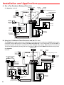
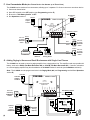
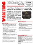
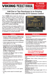
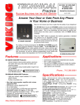
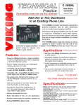
TECHNICAL
Practice
TELECOM SOLUTIONS
C-1000A
Door Entry
Controller
Practice
FOR THE
2 1 S T C E N T U RY
June 21, 2002
Add Peripherals without Changing
Your Phone System
The C-1000A Controller dramatically expands
the potential installation sites for many peripherals such as doorboxes and paging amplifiers.
Doorboxes and paging amplifiers can now be
used on single line, residential or home office
applications as well as on fully loaded systems,
because they are no longer limited to installation
on unused trunk ports.
The C-1000A allows single line phones or phone
systems to share a phone line with one or two
doorboxes or paging amplifiers. In addition, the C-1000A provides two Touch Tone controlled relays to operate door strikes
or gate openers.
Applications
Features
• Allows two Viking doorboxes or paging amplifiers
to share a single telephone line with a residential
or business telephone system
• Add one or two Viking Doorboxes to your home
or office phones
• Add paging amplifiers to provide loud ringing and
paging to businesses with single line phones or
fully loaded phone systems
• Custom ringing mode allows you to distinguish
doorbox calls from C.O. calls
• Provide commercial or residential security via twoway handsfree communication from a door or
gate
• Compatible with the following handsfree Viking
models: W-1000, W-2000A, or W-3000
• Use as a line concentrator (one fax machine or
answering machine can answer three lines)
• Call waiting tones indicate which doorbox is calling and distinguish a doorbox call from a C.O.
line call
• Calls can be placed on hold when visitors call
from the doorbox or when paging
• Provides two Touch Tone controlled N.O. or
N.C. dry contact closures (5 amp rating) for
door strikes or gate openers
• Compatible with pulse or Touch Tone phones
• Postal lock/keyless entry input
• Built-in talk battery for “No C.O.” applications
• Auxiliary contact output for doorbells, cameras, etc.
Phone...715.386.8861
[email protected]
h t t p : / / w w w. v i k i n g e l e c t r o n i c s . c o m
Specifications
Power: 120V AC/13.8V AC 1.25A, UL listed adapter provided
Dimensions: 133mm x 89mm x 44mm (5.25" x 3.5" x 1.75")
Shipping Weight: 0.9 kg (2 lb)
Environmental: 0° C to 32° C (32° F to 90° F) with 5% to 95%
non-condensing humidity
Door Strike Relay Contacts: 5A @ 30V DC/250V AC maximum
Auxiliary Relay Contacts: .5A @ 125V AC, 1A @ 30V AC
Connections: (2) RJ11 jacks, (1) 12 position terminal block
Pulse Dialing Detection: 10 pps
Talk Battery: 30V DC
Maximum Doorbox Power Supply Length: 100 ft, 24 awg wire
Installation and Applications
A. One or Two Doorboxes Sharing a Phone Line
Talk Battery Switch
See Operation, section A.
OFF
120V AC
Normally
Open
ON
VIKING©
Normally
Closed
Note: See Programming section G.
MODEL C-1000A
5A@30V DC/250V AC
maximum
Gate controllers
do not typically
require power.
VIKING
ELECTRONICS
HUDSON, WI 54016
POWER 13.8V AC
C.O. Line
or Analog
PABX/KSU
station
1
LINE IN
PHONES
2
3
4
5
6
7
Doorstrike/Magnetic Lock
DOOR
STRIKE 2
DOOR
BOX 2
DOOR
BOX 1
DOOR BOX
POWER
AUX. CONTACT
OUTPUT
DOOR ENTRY/PAGING
CONTROLLER
DOOR
STRIKE 1
13.8V AC
Adapter
included
9 10 11 12
8
STATUS
Back View
of W-1000
Unused
Trunk
Input of
PABX/KSU
Standard
Analog
Phones
Back View
of W-2000A
or
Gate controllers
do not typically
require power.
5A@30V DC/250V AC
maximum
Doorstrike/Magnetic Lock
B. Using the C-1000A with Three Doorboxes and No C.O. Line
The C-1000A can be used to control up to 3 doorboxes. If door/gate control is needed, the C-1000A must be used in
combination with the RC-3 Remote Controller (Fax Back Document 165). In this configuration, the optional RC-3 is
connected in parallel with doorbox 3 to provide up to three additional relay contacts. Note: Doorbox 3 will not have
Touch Tone dialing restriction (security). Be sure to program the RC-3 and the C-1000A with different security codes.
Talk Battery Switch
See Operation,
section A.
OFF
120V AC
13.8V AC
Adapter
included
VIKING©
Normally
Open
ON
MODEL C-1000A
POWER 13.8V AC
VIKING
ELECTRONICS
HUDSON, WI 54016
1
1 2 3 4 5 6 7 8 9 10
Door Strike 5
Door Strike 4
Door Strike 3
Back View
of W-1000
(Doorbox 3)
LINE IN
Unused Trunk
Input of
PABX/KSU
PHONES
2
4
5
6
7
8
DOOR
STRIKE 2
DOOR
BOX 2
DOOR BOX
POWER
DOOR
BOX 1
DOOR
STRIKE 1
3
Note: See Programming section G.
5A@30V DC/250V AC
maximum
DOOR ENTRY/PAGING
CONTROLLER
AUX. CONTACT
OUTPUT
RC-3 Relay Controller
Normally
Closed
Doorstrike/Magnetic Lock
9 10 11 12
STATUS
Back View
of W-1000
Analog
Phone
or
120VAC
Gate controllers do not
typically require power.
(2)
Gate controllers
do not typically
require power.
5A@30V DC/250V AC
maximum
Doorstrike/Magnetic Lock
Back View
of W-2000A
C. Using a C-1000A without a C.O. Line
Talk Battery Switch
The C-1000A can also be used without a C.O. line. This is ideal
for connecting the C-1000A to an unused trunk/line input of your
phone system or connecting to phones used only for doorbox
communication.
OFF
ON
VIKING©
1. Connect the power, required doorboxes, and doorstrike outputs (if required) as shown in section A.
MODEL C-1000A
POWER 13.8V AC
VIKING
ELECTRONICS
HUDSON, WI 54016
3. Be sure the “Talk Battery Switch” is in the ON position.
1
LINE IN
PHONES
2
3
4
5
6
7
8
DOOR
STRIKE 2
DOOR
BOX 2
DOOR BOX
POWER
DOOR
BOX 1
DOOR
STRIKE 1
AUX. CONTACT
OUTPUT
2. Connect an analog phone or PABX/KSU trunk port to the
“PHONES” output of the C-1000A.
DOOR ENTRY/PAGING
CONTROLLER
9 10 11 12
STATUS
D. Using the C-1000A with a Postal Lock/Keyless Entry
Important: Electronic components are sensitive to
static electricity. Personnel and the work area
should be grounded before handling.
International
Electronics
(800) 343-9502
1
2
3
4
5
6
7
8
9
0
Keyed or Keyless
Momentary Closure
Enter
4. See Operation section A, 5. Postal Lock.
1
LINE IN
VIKING©
6
7
8
DOOR
STRIKE 2
DOOR
BOX 2
DOOR BOX
POWER
DOOR
BOX 1
5
9 10 11 12
MODEL C-1000A
VIKING
ELECTRONICS
HUDSON, WI 54016
1
LINE IN
PHONES
2
3
4
5
6
7
8
DOOR
STRIKE 2
DOOR
BOX 2
DOOR BOX
POWER
DOOR ENTRY/PAGING
CONTROLLER
3. Program the Auxiliary Contact Output as desired (see
Programming section B).
4. See Operation section A, 6. Auxiliary Contacts.
4
DOOR
BOX 1
2. Connect doorboxes and doorstrike outputs (if required)
as shown in sections A.
3
STATUS
AUX. CONTACT
OUTPUT
1. Connect the camera or doorbell (not included) as
shown to the right. Note: The C-1000A will not supply
power to the doorbell, an adapter is necessary.
POWER 13.8V AC
E. Using the C-1000A to trigger a Camera or Doorbell
PHONES
2
DOOR
STRIKE 1
DOOR ENTRY/PAGING
CONTROLLER
DOOR
STRIKE 1
3. Connect doorboxes and doorstrike outputs
(if required) as shown in section A.
J5
MODEL C-1000A
VIKING
ELECTRONICS
HUDSON, WI 54016
AUX. CONTACT
OUTPUT
2. Connect the postal lock to the two pin header J5
at the rear of the board and replace circuit board
in the chassis.
1
2
VIKING©
POWER 13.8V AC
1. Remove the C-1000A circuit board from the
chassis.
9 10 11 12
STATUS
Doorbell
(not included)
Camera
(not included)
or
Not to Exeed
.5A @ 125V AC
1A @ 30V AC
SECURITY
(3)
F. Line Concentrator Mode (One Telcom Device Can Answer up to Three Lines)
The C-1000A can be used as a line concentrator, allowing up to 3 separate C.O. lines to connect to one telcom device.
1. Connect as shown below.
2. Move DIP switch 3 to the OFF position (see Programming section E).
3. Be sure the “Talk Battery Switch” is OFF.
Dip Switches
1 2 3
ON
120V AC
VIKING©
13.8V AC
Adapter
included
MODEL C-1000A
OFF
POWER 13.8V AC
VIKING
ELECTRONICS
HUDSON, WI 54016
1
2
3
4
5
6
7
8
DOOR
STRIKE 2
DOOR
BOX 2
DOOR BOX
POWER
DOOR
BOX 1
AUX. CONTACT
OUTPUT
DOOR ENTRY/PAGING
CONTROLLER
DOOR
STRIKE 1
4. See Operation section C.
Talk Battery Switch
9 10 11 12
OFF
C.O. Line
or Analog
PABX/KSU
station
Line 1
LINE IN
PHONES
ON
STATUS
Line 3
Red
Green
C.O. Line
or Analog
PABX/KSU
station
or
Line 2
Red
Answering
Machine
Fax Machine
Green
Standard
Analog Phone
C.O. Line
or Analog
PABX/KSU
station
G. Adding Paging to Homes and Small Businesses with Single Line Phones
The C-1000A can be used to control a paging amplifier from a single phone line. The amplifier used must provide talk
battery, such as the PA-2A (Fax Back Document 485) or CPA-7B (Fax Back Document 455). If need be, a doorbox
or a second paging amplifier may also be added to the C-1000A Doorbox 2 terminals (see Installation section A).
Note: The C-1000A must be programmed to be in the Paging Mode, ✱4 (see Programming section B and Operation
section B).
120V AC
VIKING©
13.8V AC
Adapter
included
MODEL C-1000A
POWER 13.8V AC
VIKING
ELECTRONICS
HUDSON, WI 54016
C.O. Line
or Analog
PABX/KSU
station
1
2
3
4
5
6
7
8
DOOR
STRIKE 2
DOOR
BOX 2
DOOR BOX
POWER
DOOR
BOX 1
DOOR
STRIKE 1
AUX. CONTACT
OUTPUT
DOOR ENTRY/PAGING
CONTROLLER
Talk Battery Switch
9 10 11 12
OFF
LINE IN
PHONES
ON
STATUS
PAGING/LOUD RINGING
AMPLIFIER SYSTEM
120V AC
VIKING
ELECTRONICS
HUDSON,WI 54016
PAGING
RINGING
VIKING
Unused
Trunk
Input of
PABX/KSU
(4)
©
MODEL PA-2A
Standard
Analog
Phones
or
13.8VAC
RINGING
LINES
1-3
4-6
1
BATTERY
FEED
OFF ON
2
3
4
5
Programming
A. Accessing the Programming Mode
1. Accessing the Programming Mode Locally (Security Code Bypass Mode)
a. Move DIP switch 2 from OFF to ON (see Programming section E).
b. Call into the C-1000A from a Touch Tone phone. Note: Call in from another line to avoid C.O. busy signals, etc.
c. Answer the call using the device on the “PHONES” port.
d. A double beep will indicate that you have accessed the programming mode.
e. You can now Touch Tone program the features listed in section B below.
f. When finished programming, move DIP switch 2 to the OFF position.
Note: Programming from a cell-phone may not be suitable in areas with weak coverage.
2. Accessing the Programming Mode Remotely
a. Call into the C-1000A from a Touch Tone phone. Note: Call in from another line to avoid C.O. busy signals,etc.
b. Answer the call using the device on the “PHONES” port.
c. From either phone enter ✱ followed by the six digit security code (see Programming section D).
d. A double beep will indicate that you have accessed the programming mode.
e. You can now Touch Tone program the features listed in section B below.
Note: Programming from a cell-phone may not be suitable in areas with weak coverage.
B. Quick Programming Features
Memory
Enter Digits - then - Location
Door strike 1 activation time .5 - 10 seconds (see “Note” below) ............................ 2 digits
Door strike 2 activation time .5 - 10 seconds (see “Note” below) ............................ 2 digits
Auxiliary contact activation time .5 - 10 seconds (see “Note” below) ...................... 2 digits
Note: 00 = .5 seconds, 01-10 = 1-10 seconds, factory set to 00 (.5 seconds).
Auxiliary contact latched while either doorbox is activated ...................................... 11
Auxiliary contact activated in custom ring cadence ................................................. 12
Security Code (factory set to 845464) ..................................................................... 6 digits
(00-10)
(00-10)
(00-10)
+
+
+
#01
#02
#03
(0-9)
+
+
+
#03
#03
#47
Enter Digits
Disable all special modes listed below (factory default) .......................................... ✱0
Doorbell mode ........................................................................................................ ✱1
Custom ring mode ................................................................................................... ✱2
Multiple relay activation mode ................................................................................. ✱3
Paging mode ........................................................................................................... ✱4
Inhibit latching commands mode ............................................................................ ✱6
To reset to factory settings ...................................................................................... ###
Note: Multiple modes may be selected.
C. Programming Examples
Programming the C-1000A...
Enter
1. ...to set door strike 1 to activate for 3 seconds
03 #01
2. ...to set the auxiliary contacts to activate a camera while either doorbox is activated
11 #03
3. ...to set the auxiliary contacts to activate an external ringer or strobe light in a custom ring cadence
while either doorbox is ringing
12 #03
4. ...to have doorboxes ring phones in a custom ring pattern
✱2
D. Security Code
This six digit number can be used to access the programming mode. The security code has been factory set to 845464
(V-I-K-I-N-G). It is recommended that you change the security code to a personal 6 digit number. To change the security code, access programming (see Programming section A). Enter six digits 0-9 followed by #47. If you have forgotten your security code, follow the steps in Programming section A, 1. Accessing the Programming Mode
Locally. Note: The security code must be six digits in length and can NOT contain a ✱ or #.
(5)
E. Dip Switch Programming
3
Mode
Selection
OFF
DOOR ENTRY/PAGING
CONTROLLER
OFF - Line Concentrator Mode
ON - Normal Operation (factory setting)
1
LINE IN
PHONES
2
3
4
5
6
7
8
DOOR
STRIKE 2
OFF - Normal Mode (factory setting)
ON - Security Code Bypass Mode
DOOR
BOX 2
2
Security Code
Bypass Mode
VIKING
ELECTRONICS
HUDSON, WI 54016
DOOR BOX
POWER
OFF - .5 seconds (factory setting)
ON - 10 seconds
DOOR
BOX 1
Doorstrike
Activation Time
MODEL C-1000A
DOOR
STRIKE 1
1
VIKING©
Dip Switches
1 2 3
ON
Operation
AUX. CONTACT
OUTPUT
Description
POWER 13.8V AC
Switch
9 10 11 12
STATUS
F. Mode Descriptions
Entering these codes while in programming will switch the C-1000A into the corresponding mode.
Disable Special Modes (✱0): This command disables (clears) all the special modes listed below. Enter this command
before programming the rest of the selections to be sure no unwanted modes are set.
Doorbell Mode (✱1): In this mode, the ring signal from either doorbox is prevented from going through to the
“PHONES” port. This is useful when a conventional door bell is connected to the auxiliary contacts. Now when someone activates a doorbox, the doorbell will chime rather than the phone ringing (see Programming section B).
Custom Ring Mode (✱2): With this mode selected, the ring signal from the device ports are interrupted in a double
burst pattern, making it easier to determine if the incoming call is from a doorbox or the C.O. line.
Multiple Relay Activation Mode (✱3): If selected, after a door strike command is entered, the phone is switched back
to the doorbox port so additional doorstrike (relay activation) commands can be entered. This is useful when letting
someone through your gate with the first command then unlocking your front doorstrike with a second command. To
return to the call on hold, enter “#”.
Paging Mode (✱4): In this mode a paging system that provides talk battery (Viking PA-2A or CPA-7B) can be connected to one of the doorbox ports. When the person on the phone wants to make a page, they can enter “#” and a “1”
or “2” depending on which port the paging amplifier is on. After the announcement is made another “#” will return them
to the phone conversation.
Inhibit Latching Commands Mode (✱6): In some installations it is critical that the door strike or door actuator not be
turned on for long periods of time. To prevent this from happening, enter ✱6 when in programming. In this mode, the
toggle command (✱#) and the continuous activation command (✱1) are ignored.
VIKING©
MODEL C-1000A
Normally
Open
VIKING
ELECTRONICS
HUDSON, WI 54016
1
LINE IN
PHONES
2
3
4
5
6
7
8
DOOR
STRIKE 2
DOOR
BOX 2
DOOR BOX
POWER
DOOR
BOX 1
DOOR
STRIKE 1
DOOR ENTRY/PAGING
CONTROLLER
AUX. CONTACT
OUTPUT
Selection shunts are provided for each door strike
relay and the auxiliary relay. Place the shunt in the left
position for normally open contacts, or in the right position for normally closed contacts. These shunts are
located directly above the terminal block positions that
they control.
POWER 13.8V AC
G. N.O./N.C. Contact Selection
9 10 11 12
Normally
Closed
STATUS
Operation
A. Doorbox Controller
1. Communicating with the Doorbox
a. Visitor Initiated Call
A visitor pressing the “Call” button will cause the phones connected to the “PHONES” port to ring. Simply
answer your phone to converse with the visitor.
b. Monitoring Doorboxes
A doorbox may be monitored from any phone connected to the C-1000A by Touch Tone dialing a “#” followed by
a Touch Tone “1” or “2” to monitor doorbox 1 or doorbox 2 respectively. This feature is not available for pulse
dialing phones. Note: Do not attempt doorbox monitoring while a call is in progress, the call will be disconnected.
Note: When monitoring, the auxiliary contact will only work on the Continuous Mode (11).
(6)
2. Placing C.O. Line Calls on Hold
If a C.O. line call is in progress and a doorbox is activated, a single or double “call waiting” tone will be heard indicating doorbox 1 or doorbox 2 is calling. To place the in-progress call on hold and answer the calling doorbox, simply dial a Touch Tone “#”, pulse dial a “2” or hook flash twice.
3. Activating a Doorstrike, Magnetic Lock or Gate Controller
To activate a relay contact, you must be communicating with a doorbox. Simply Touch Tone dial “✱ ✱”, pulse dial a
“3” or hook flash three times. Two confirmation tones will be heard and the relay will be activated for the programmed doorstrike activation time. The phone will then be returned to the C.O. line. If a call was in progress, the
original caller will be taken off hold to continue the conversation. To return to the original call without activating a
relay, Touch Tone dial “#”, pulse dial a “2” or hook flash twice.
4. Features
Touch Tone
Commands
Activate doorstrike relay 1 or 2 .................................................. ✱ ✱
Continuously activate doorstrike relay 1 or 2 ............................ ✱ 1
Continuously de-activate doorstrike relay 1 or 2 ....................... ✱ 0
Activate opposite doorstrike relay ............................................. ✱ 2
Toggle relay from last position ................................................... ✱ #
Answer or disconnect a doorbox call ......................................... #
Monitor doorbox 1 ..................................................................... # 1
Monitor doorbox 2 ..................................................................... # 2
Pulse Dial/Flash Commands
Pulse dial 3 or hook flash 3 times
Pulse dial 2 or hook flash 2 times
Note: When on the C.O. line, if a Touch Tone other than # is entered, any additional Touch Tones in that dial string
will be ignored. To regain control of the C-1000A, the phone must be momentarily placed on-hook.
5. Postal Lock/Keyless Entry
When a momentary postal lock contact closure is made across pins JP5 (see Installation section D), the doorstrike
1 contact will activate for the programmed time.
6. Auxiliary Contacts
The auxiliary contacts are a separate set of contacts that can be programmed (see Programming section B) to activate in different patterns when doorbox 1 or doorbox 2 is off hook. A momentary activation, a continuous activation
while the doorbox is off-hook, and a ring cadence pattern are available.
a. Timed Activation
If an auxiliary contact activation time is programmed (two digits 00-10 followed by #03), when either doorbox is
activated, the auxiliary contacts will activate for the programmed time (.5 - 10 seconds). This is ideal for operating a doorbell or chime.
b. Continuous Activation
If the auxiliary contact is programmed to continuously activate (11 followed by #03), while either doorbox is ringing or off-hook, the auxiliary contacts will latch. This is ideal for controlling cameras, lights, etc.
c. Ring Cadence Activation
If the auxiliary contact is programmed to custom ring cadence (“12 #03”) when doorbox 1 is activated, a repeating 1 second on and 3 seconds off contact pattern is generated. If doorbox 2 is activated, a repeating double
burst contact pattern is generated with 3 seconds off between patterns.
B. Paging Controller
In this mode a paging system that provides talk battery (Viking PA-2A or CPA-7B) can be connected to one of the doorbox ports. When the person on the phone wants to make a page, they can enter “#” and a 1 or 2 depending on which
port the paging amplifier is on. After the announcement is made, if a call was in progress, another “#” will return them
to the phone conversation.
C. Line Concentrator
The first ringing line will ring to the “PHONE” port of the C-1000A. On outbound calls, the C-1000A will default to the
primary line (line connected to the “Line In” port). To access the lines connected to “Doorbox 1” port or “Doorbox 2”
port, simply dial Touch Tones “#1” or “#2” respectively. Note: DIP switch 3 must be in the OFF position.
(7)
Door Boxes
These Viking doorboxes are designed to be installed
on the unused telephone line input of nearly any
phone system.
When the Call button is pressed, the doorbox generates a standard ring cadence for an adjustable number of rings. To converse with the visitor, the inside
party simply answers the call from the phone of their
choice. For noisy environments, the doorbox’s “pushto-talk” feature may be used.
W-2000A
W-1000
The flush mount W-1000 doorbox is made of black
powder painted aluminum. The surface mount W-2000A doorbox is made of UV
resistant plastic. The flush mount W-3000 doorbox is made of vandal and weather resistant stainless steel.
The W-1000 and W-3000 may be surface mounted using Viking’s VE-5x5 backbox. For more information on the VE-5x5, retrieve Fax Back Document 424.
Fore more information on the W-1000 or W-2000A, retrieve Fax Back Document
170. For more information on the W-3000, retrieve Fax Back Document 180.
W-3000 with VE-5x5
Advanced Door Entry
The C-2000 allows up to 4 entry phones to call into your existing residential or business phones or phone system. Tenants may answer the call,
converse with the visitor and activate a contact closure to control electronic gates or door strikes.
The C-2000 provides “Caller ID,” “Call Waiting ID” and “Call Waiting” tones
when the phone line is in use. Tenants may gain entry at each gate by
entering a Touch Tone keyless entry code.
Create an advanced door entry system by using the C-2000 in combination
with the K-1700-3 handsfree phone.
The K-1700-3 features a vandal and weather resistant stainless steel faceplate with a heavy duty keypad. The K-1700-3 comes complete with a standard, flush mount, rough-in box. In addition, the K-1700-3 may be surface mounted using Viking’s VE-6x7 backbox. For
more information on the VE-6x7, retrieve
Fax Back Document 424.
C-2000
For more information on the C-2000,
retrieve Fax Back Document 156. For
more information on the K-1700-3, retieve
Fax Back Document 157.
K-1700-3 with VE-6x7
K-1700-3
Product Support Line...715.386.8666
Fax Back Line...715.386.4345
Due to the dynamic nature of the product design, the information contained in this document is subject to change without notice. Viking Electronics, and its affiliates and/or
subsidiaries assume no responsibility for errors and omissions contained in this information. Revisions of this document or new editions of it may be issued to incorporate
such changes.
Fax Back Doc 155
(8)
Printed in the U.S.A.
ZF301500 Rev A