1
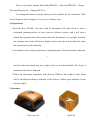
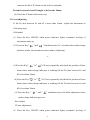
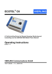
Self-leveling Rotary Laser FRE201
Art.No. R154
Service Manual
HEDÜ GmH
www.hedue.de
1. Instrument & Accessories
Main body
Telecontrolling device
Charger
Detector & Clamp
1
This set of product include Main body(FRE201)、Detector(FRD100)、Clamp、
Telecontrolling device、Charger(FC101)。
5# rechargeable battery and dry battery are all available for the instrument. Take
out the batteries after loosing the cover screw of battery case.
1.1 Operations
1.Press the Key ON/OFF,the laser head of instrument will rotate freely to form a
horizontal scanning-surface of laser beam as reference surface, and it will emit a
plumb line upwards and a down point when the instrument is set upright. And also
the spinning laser head will form a plumb surface and emit a horizontal line when
the instrument is set horizontally.
2.According to the working requirement,spinning speed of laser head can be adjusted,
2
and also make laser head step-move right or left, or scan directionally. The slope of
instrument can also be adjusted
3.When the instrument cooperates with detector FRD100, the height of laser beam
will be decided according to indicator of the detector (When green indicator on the
detector lights).
2. Structure
Top-cover Set
3
Shell Set
Underpan Set
Pendulum
4
2.1 Top-cover Set
Bombing illustration
5
Serial number
Code
Name
Quantity
1
FRE101-201
Top-cover
1
2
FRE101-302
Shielding glass
1
3
FRE101-202
Top-cover base
1
4
FRE101-213
Gasket I
1
5
FRE101-301
Glass
4
6
FRE101-211
Gasket II
1
7
FRE101-207
Glass base
1
8
GB/T845-1985
9
GB/T 96-1985
10
GB/T845-1985
Screw(ST2.2×
9.8)
φ3 Gasket
Screw(ST2.9×
9.8)
6
2.2 Shell Set
Bombing illustration
7
4
4
8
Serial number
Code
Name
Quantity
1
FRE101-203
Shell
1
2
FRE101-205
Handle
1
Keyboard
1
3
4
FRE101-127
Shielding board
1
5
FRE101-304
Keyboard sticker
1
6
FRE101-121
Gasket III
4
7
GB/T818-2000
Screw(M3×6)
3
8
GB/T819.1-2000
Screw(M2.5×6)
3
9
GB/T819.1-2000
Screw(M2.5×
12)
4
10
GB/T6170-2000
Nut (M2.5)
7
8
2.3 Underpan Set
Power plug
(4 cartridges)
Y-axis leveling
motor
Y-axis leveling
motor plug
(6 cartridges)
Alarming circle
Alarming ring
Alarming plug
(5 cartridges)
Underpan Set
9
X-axis leveling
motor
X-axis leveling
motor plug
(6 cartridges)
Bombing illustration
10
Serial
number
Code
Name
Quantity
1
FRE101-204
Base
1
2
JP30-2-400
Motor set
2
Alarming PCB
1
Alarming sheet
4
3
4
FRE101-123
5
FRE101-217
6
Spring strip I
1
7
FRE101-214
FRE101-218
Spring strip IV
1
8
FRE101-216
Spring
4
9
FRE101-215
Spring strip II
2
10
Batteries cover
1
11
FRE101-206
JP30A-026
Base foot
6
12
GB/T845-1985
Screw(M2.2×9.8)
4
13
GB/T818-2000
Screw(M3×6)
6
φ3 Gasket
6
Screw(M2.2×5.5)
5
Spring strip III
14
15
GB/T845-1985
11
1
2.4 Pendulum
Y-axis sensor plug
(4 cartridges)
Scanning motor plug
(4 cartridges)
Z-axis sensor plug
(4 cartridges)
Down point power
plug (4 cartridges)
X-axis sensor plug
(4 cartridges)
12
Z-sensor
Y-sensor
X-sensor
Bombing illustration
13
Serial
number
1
2
3
4
5
6
7
8
9
Code
Name
Quantity
FRE101-307
FRE101-104
FRE101-105
FRE101-112
FRE101-107
FRE101-110
FRE101-126
FRE101-106
FRE101-125
1
1
1
1
1
1
1
1
1
10
FRE101-103
11
12
13
14
FRE101-111
FRE101-117
FRE101-102
FRE101-101
15
GB/T80-2000
Pentagon prism 10×10
Prism base
Scanning base
Raster
Scanning gear II
Gasket I
Nut II
Scanning gear I
Leveling board
Universal ring
holder
Gasket II
Pressing ring
Universal ring
Pendulum
Stabilizing screw( M2.5
×3)
Bearing (6801ZZ)
Bearing (623ZZ)
φ3×12.8 Roller pin
φ3×15.8 Roller pin
Stabilizing screw(M3
×4)
Screw(M2.5×5)
Nut(M2.5)
Motor
4
2
2
16
1
4
4
1
1
2
2
14
17
18
19
20
GB/T80-2000
21
22
23
GB/T818-2000
12
2
2
1
2.5 PCB
Scanning optical
coupler socket
(4 cartridges)
Power socket
(4 cartridges)
Panel socket
(16 cartridges)
15
Y-sensor socket
(4 cartridges)
X-sensor socket
(4 cartridges)
Power socket
(4 cartridges)
Y-leveling motor
socket (6 cartridges)
Scanning motor
socket (2 cartridges)
X-leveling motor
socket (6 cartridges)
Alarm socket
(5 cartridges)
Z-sensor socket
(4 cartridges)
16
2.6 Instrument Assembling
Bombing illustration
17
Serial
number
Code
Name
Quantity
1
FRE101-1-100
Top-cover Set
1
2
FRE101-212
Gasket III
1
3
FRE101-1-200
Shell Set
1
PCB
1
4
5
FRE101-200
Pendulum
1
6
FRE101-210
Gasket I
1
7
FRE101-1-300
Underpan Set
1
8
GB/T818-2000
Screw(M3×8)
4
9
GB/T818-2000
Screw(M3×8)
4
10
GB/T818-2000
Screw(M3×8)
8
11
GB/T818-2000
Screw(M3×8)
2
18
3. Instrument Checking
(1) Place the instrument at the point of 50m in front of wall (or set a scaleplate at the
point of 50m away from the instrument), and then adjust the level of the base
approximately to aim the X1 to the wall (or scaleplate), as depicted below:
(2) After switching on the power, use the detector measuring the h1 of X1-beam on
the wall or scaleplate.
(3) Loose the screw of the tripod ,and then turn around the instrument 180°to
19
measure the h2 of X2-beam on the wall or scaleplate.
D-value between h1 and h2 ought to be less the 10mm.
(4) Check the Y-beam in the same way.
3.1 Level adjusting
If the D-value between h1 and h2 is more than 10mm,adjust the instrument as
following steps:
Old model:
(1) Press the Key ON/OFF when power indicator lights, automatic leveling of
instrument starts up.
(2) Press the Key“
”and“
”simultaneously for 3 seconds when undervoltage
indicator winks, the instrument enters mode of adjusting.
20
(3)Press the Key“
”or“
”of X-axis repeatedly and check the position of laser
beam when undervoltage indicator is winking till the D-value between h1 and
h2 is less than 10mm.
(4) Press the Key“
”or“
”of Y-axis repeatedly and check the position of laser
beam when undervoltage indicator is winking till the D-value between h1 and
h2 is less than 10mm.
(5) Press the Key“
”and“
”simultaneously to hold the adjustment when
undervoltage indicator goes out.
New model:
I.Y-axis adjustment
(1) Press the Key ON/OFF when power indicator lights, automatic leveling of
21
instrument starts up.
”and“
(2) Press the Key“
”simultaneously for 3 seconds when mode
indicator winks, the instrument enters mode of adjusting.
(3) Press the Key“
”or“
”of Y-axis repeatedly and check the position of laser
beam when mode indicator is winking till the D-value between h1 and h2 is less
than 10mm.
”and“
(4) Press the Key“
”simultaneously to hold the adjustment when
mode indicator goes out.
Note: If the instrument is set horizontally, Y-axis adjustment stands for Z-axis
adjustment.
II.X-axis adjustment
22
(1) Press the Key ON/OFF when power indicator lights, automatic leveling of
instrument starts up.
(2) Press the Key“
”and“
”simultaneously for 3 seconds when undervoltage
indicator winks, the instrument enters mode of adjusting.
(3) Press the Key“
”or“
”of X-axis repeatedly and check the position of laser
beam when undervoltage indicator is winking till the D-value between h1 and h2
is less than 10mm.
(4) Press the Key“
”and“
”simultaneously to hold the adjustment when
undervoltage indicator goes out.
Note: i. If canceling the adjustment, please shut off the instrument and then turn on
it.
23
ii. If the adjusting range exceed range permitted, the power indicator will
wink.
Notices:Once the D-value exceeds the error range that instrument permits, please
contact the supplier to repair the instrument.
4.Horizontal-line Adjustment
4.1 Checking
(1) Place the instrument between two walls with the distance of 30m (or two
scaleplates with the distance of 30m).
24
(2) Place the instrument according to horizontal setting manner and then adjust
the instrument.
(3)Switch on the power, and then measure the middle point of the laser beam on
the wall (or scaleplate): hA, hB and hA′, hB′.
(4) △1=hA-hA′, △2=hB-hB′
D-value between △1 and △2 ought to be less than 6mm.
4.2 Adjusting
25
If D-value between Δ1and Δ2 is more than 4mm ,adjust the instrument in
the same way of level adjusting. Please refer to 3. and 3.1 in details.
5. Detector
5.1 Principle
The laser beam is received by silicon photocell. After amplifying and judging
the signal received, the detector will send out command signal to control the
display of LCD and the buzzer.
26
LCD illustration
27
States of buzzer:upward bias alarm、downward bias alarm、accurate-orientated alarm
(prolonged sound)
6.Malfunctions & Eliminations
A. Failures in starting up
(1)
Symptoms:
After pressing the Key ON/OFF, power indicator can’t light and also the
instrument doesn’t start up.
(2) Causes:
a. Poor contact of keys on the panel or panel plug.
b. Poor contact of batteries or power plug, and insufficient power,
c. Troubles of PCB.
28
(2)
Eliminations:
a. Take off the shell,and renew the panel or connect the power plug with
PCB well.
b. Take down the cover of battery case to check whether there are some
dirt or rust between the spring and spring strip,and clear off them if it is
true;Recharge
the batteries till power is sufficient and then detach
the shell to connect the power plug with PCB well.
c. Detach the shell to change the PCB.
d. Please contact the supplier when the instrument still doesn’t start up
after all your effort above.
B. No spinning of laser head.
29
(1) Symptoms:
The laser beam is being emitted but the laser head doesn’t rotate after
instrument is power on.
(2) Causes:
a. Center to center distance of gear is not suitable,gearing is abnormal.
b. Troubles of scanning motor.
c. Laser head has touched the optical coupler.
d. Troubles of PCB.
(3) Eliminations:
a. Take off the shell to readjust the center-to-center distance of the gear.
b. Change the scanning motor after taking off the shell.
30
c. Detach the shell to readjust the space between laser head and optical
coupler.
d. Change the PCB.
C. No responses of detector
(1)Symptoms:
Press the Key ON/OFF, the LCD doesn’t display.
(2)Causes:
a. Install the batteries according to the wrong electrode.
b. Panel plug drops out.
c. Troubles of PCB.
(3)Eliminations:
31
a. Take off the cover of battery case to install the batteries correctly.
b. Detach the panel cover of detector to insert the plug again.
c. Please take the detector back to the manufacturer to repair it, if there are
some troubles in PCB.
D. No sound of buzzer.
(1)Symptoms:
There is no sound of buzzer after pressing any keys on the panel.
(2) Causes:
a. Buzzer plug drops out.
b. Troubles of PCB.
(3) Eliminations:
32
a. Connect the buzzer plug with the PCB well.
b. Please take the detector back to the manufacturer to repair it, if
there are some troubles in PCB.
33