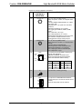
1
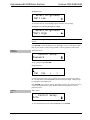
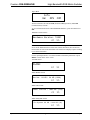
Crestron CEN-RGBHVHB High-Bandwidth RGB Matrix Switcher Operations Guide Important Safety Instructions • • • • • • • • • • • • • • • • • • Read these instructions. Keep these instructions. Heed all warnings. Follow all instructions. Do not use this apparatus near water. Clean only with dry cloth. Do not block any ventilation openings. Install in accordance with the manufacturer's instructions. Do not install near any heat sources such as radiators, heat registers, stoves, or other apparatus (including amplifiers) that produce heat. Do not defeat the safety purpose of the polarized or grounding-type plug. A polarized plug has two blades with one wider than the other. A grounding-type plug has two blades and a third grounding prong. The wide blade or the third prong are provided for your safety. If the provided plug does not fit into your outlet, consult an electrician for replacement of the obsolete outlet. Protect the power cord from being walked on or pinched particularly at plugs, convenience receptacles, and the point where they exit from the apparatus. Only use attachments/accessories specified by the manufacturer. Use only with the cart, stand, tripod, bracket or table specified by the manufacturer or sold with the apparatus. When a cart is used, use caution when moving the cart/apparatus combination to avoid injury from tip-over. Unplug this apparatus during lightning storms or when unused for long periods of time. Refer all servicing to qualified service personnel. Servicing is required when the apparatus has been damaged in any way, such as power-supply cord or plug is damaged, liquid has been spilled or objects have fallen into the apparatus, the apparatus has been exposed to rain or moisture, does not operate normally, or has been dropped. Disconnect power prior to connecting or disconnecting equipment. Do not install in direct sunlight. The apparatus must be installed in a way that the power cord can be removed either from the wall outlet or from the device itself in order to disconnect the mains power. Prevent foreign objects from entering the device. WARNING: TO REDUCE THE RISK OF FIRE OR ELECTRIC SHOCK, DO NOT EXPOSE THIS APPARATUS TO RAIN OR MOISTURE. THE APPARATUS SHALL NOT BE EXPOSED TO DRIPPING OR SPLASHING. OBJECTS FILLED WITH LIQUIDS, SUCH AS VASES, SHOULD NOT BE PLACED ON THE APPARATUS. WARNING: TO PREVENT ELECTRIC SHOCK, DO NOT REMOVE COVER. THERE ARE NO USER SERVICEABLE PARTS INSIDE. ONLY QUALIFIED SERVICE PERSONNEL SHOULD PERFORM SERVICE. The lightning flash with arrowhead symbol, within an equilateral triangle, is intended to alert the user to the presence of uninsulated “dangerous voltage” within the product's enclosure t hat may be of sufficient magnitude to constitute a risk of electric shock to persons. The exclamation point within an equilateral triangle is intended to alert the user to the presence of important operating and maintenance (servicing) instructions in the literature accompanying the appliance. WARNING: THIS IS AN APPARATUS WITH CLASS I CONSTRUCTION. IT SHALL BE CONNECTED TO AN ELECTRICAL OUTLET WITH AN EARTHING GROUND TERMINAL. IMPORTANT: This device can be used with Class 2 output wiring. Regulatory Compliance This product is Listed to applicable UL Standards and requirements by Underwriters Laboratories Inc. As of the date of manufacture, the CEN-RGBHVHB has been tested and found to comply with specifications for CE marking and standards per EMC and Radiocommunications Compliance Labelling. Federal Communications Commission (FCC) Compliance Statement CAUTION: Changes or modifications not expressly approved by the manufacturer responsible for compliance could void the user’s authority to operate the equipment. NOTE: This equipment has been tested and found to comply with the limits for a Class B digital device, pursuant to part 15 of the FCC Rules. These limits are designed to provide reasonable protection against harmful interference in a residential installation. This equipment generates, uses and can radiate radio frequency energy and, if not installed and used in accordance with the instructions, may cause harmful interference to radio communications. However, there is no guarantee that interference will not occur in a particular installation. If this equipment does cause harmful interference to radio or television reception, which can be determined by turning the equipment off and on, the user is encouraged to try to correct the interference by one or more of the following measures: • Reorient or relocate the receiving antenna • Increase the separation between the equipment and receiver • Connect the equipment into an outlet on a circuit different from that to which the receiver is connected • Consult the dealer or an experienced radio/TV technician for help Industry Canada (IC) Compliance Statement CAN ICES-3(B)/NMB-3(B) The specific patents that cover Crestron products are listed at patents.crestron.com. Crestron, the Crestron logo, Cresnet, Crestron e-Control, Crestron Studio, Crestron Toolbox, e-Control, Fusion RV, and SystemBuilder are either trademarks or registered trademarks of Crestron Electronics, Inc. in the United States and/or other countries. Other trademarks, registered trademarks, and trade names may be used in this document to refer to either the entities claiming the marks and names or their products. Crestron disclaims any proprietary interest in the marks and names of others. Crestron disclaims any proprietary interest in the marks and names of others. Crestron is not responsible for errors in typography or photography. This document was written by the Technical Publications department at Crestron. ©2013 Crestron Electronics, Inc. Crestron CEN-RGBHVHB High-Bandwidth RGB Matrix Switcher Contents High-Bandwidth RGB Matrix Switcher: CEN-RGBHVHB 1 Introduction ............................................................................................................................... 1 Features and Functions ................................................................................................ 1 Specifications .............................................................................................................. 3 Physical Description .................................................................................................... 6 Setup ........................................................................................................................................ 13 Network Wiring ......................................................................................................... 13 Identity Code ............................................................................................................. 13 Installation ................................................................................................................. 14 Hardware Hookup ..................................................................................................... 16 Uploading and Upgrading ........................................................................................................ 18 Establishing Communication ..................................................................................... 18 Programs and Firmware ............................................................................................ 19 Program Checks ........................................................................................................ 20 Operation ................................................................................................................................. 21 Menu Structure .......................................................................................................... 21 Setup and Informational Screens ............................................................................... 21 Routing Signals ......................................................................................................... 41 Sync Mode................................................................................................................. 42 Paging Mode.............................................................................................................. 42 Problem Solving ...................................................................................................................... 43 Troubleshooting......................................................................................................... 43 Check Network Wiring.............................................................................................. 43 Reference Documents ................................................................................................ 44 Further Inquiries ........................................................................................................ 44 Future Updates .......................................................................................................... 44 Return and Warranty Policies .................................................................................................. 45 Merchandise Returns / Repair Service ...................................................................... 45 Crestron Limited Warranty........................................................................................ 45 Operations Guide – DOC. 7157C Contents • i Crestron CEN-RGBHVHB High-Bandwidth RGB Matrix Switcher High-Bandwidth RGB Matrix Switcher: CEN-RGBHVHB Introduction Crestron® High-Bandwidth RGB Matrix Switchers deliver extreme performance for the most demanding presentation environments. With class-leading 800 MHz bandwidth, low crosstalk, and super wide response, the CEN-RGBHVHB8X4, CEN-RGBHVHB8X8, CEN-RGBHVHB12X4, and CEN-RGBHVHB12X8 (hereinafter collectively referred to as CEN-RGBHGVHB) easily surpass any requirement for high-performance, high-resolution analog video and computer signal routing. Factor in their enhanced audio DSP, very low power consumption, and native Crestron system integration and any of these is a solid winner for all analog video and audio signal routing applications. Features and Functions • • • • • • • • • • • • • • • • Operations Guide – DOC. 7157C Ultra high bandwidth matrix switcher 8 x 4 in CEN-RGBHVHB8X4 8 x 8 in CEN-RGBHVHB8X8 12 x 4 in CEN-RGBHVHB12X4 12 x 8 in CEN-RGBHVHB12X8 800 MHz video bandwidth (-3 dB) Incredibly wide response and low crosstalk Stereo audio signal routing with breakaway Audio DSP with volume, tone, and graphic EQ Paging mode with automatic ducking Professional balanced audio inputs and outputs Audio input level compensation Video input sync detection Video-follow-sync switching technology Adjustable video and audio blanking Selectable input sync impedance on all inputs LCD front panel for easy setup and standalone operation Crestron system integration via Cresnet® or Ethernet Very low power consumption and a quiet fanless design 3-space rack mountable High-Bandwidth RGB Matrix Switcher: CEN-RGBHVHB • 1 High-Bandwidth RGB Matrix Switcher Crestron CEN-RGBHVHB 800 MHz Bandwidth Matrix Router The CEN-RGBHVHB is capable of routing up to eight (CEN-RGBHVHB8X4, CEN-RGBHVHB8X8) or 12 (CEN-RGBHVHB12X4, CEN-RGBHVHB12X8) computer or video sources to up to four (CEN-RGBHVHB8X4, CEN-RGBHVHB12X4) or eight (CEN-RGBHVHB8X8, CEN-RGBHVHB12X8) display devices. Its five matrix levels accommodate any combination of analog RGBHV, HD/component, S-video and composite signals. Ultra high bandwidth and wide response ensure optimum performance for every signal as part of any AV system. Sync impedances for each input are selectable from the front panel or software to accommodate both short and long cable runs. Glitch-free Switching Video-follow-sync switching ensures a smooth transition when selecting between non-synchronous sources. Adjustable blanking allows each display device time to lock to the new sync signal before displaying the video image whenever a new source is selected. Sync Detection Sync detection on each H and V input measures the sync rates of every RGBHV source and allows their values to be viewed on the front panel display, on the control system touch screen, or through Crestron’s Fusion RV® software.* Audio Routing & DSP Professional audio signal processing affords enhanced, high-performance audio routing and control, potentially eliminating the need for additional audio components. Each stereo output features real time controllable volume, bass, treble, and mute controls, plus 5-band EQ with customizable presets. Programmable input level compensation helps ensure compatibility with a wide range of pro and semi-pro sources. Automatic blanking achieves a pop-free transition when switching between sources, while audio breakaway capability allows the routing of audio signals to follow video or be switched independently. The entire audio signal path has been designed from the ground up to deliver ultra quiet, distortion-free sound quality — whether feeding sensitive amplifiers, assistive listening devices, or recording and broadcast equipment. Paging Mode Built-in page override functionality simplifies system design, employing automatic mixing and ducking for a single audio paging source. When set to Paging mode, an audio signal at the last input channel is automatically distributed to every output while the signals currently routed to each output are attenuated or “ducked” to allow the paging signal to be heard. The sensitivity and ducking amount are fully adjustable for smooth paging behavior and a natural transition back to the previous audio state. Full-featured Front Panel The CEN-RGBHVHB is fully operable out-of-the-box for use as a standalone switcher. Featuring an informative LCD display, quick-adjust knob, and quick access buttons, the front panel supports essential switcher operation without requiring a computer or control system. Advanced setup is available through Crestron Toolbox™ software. All signal routing, input impedances, and audio settings are stored in non-volatile memory onboard the switcher. * Sync detection reports discrete H and V signals only. 2 • High-Bandwidth RGB Matrix Switcher: CEN-RGBHVHB Operations Guide – DOC. 7157C Crestron CEN-RGBHVHB High-Bandwidth RGB Matrix Switcher Customizable label strips are provided on the front panel for clear designation of its inputs and outputs using Crestron Engraver software or standard 3/8” tape labels. Names may also be entered through software to appear on the LCD display during operation. For security, front panel controls can be password protected or locked out. Crestron System Integration Via Cresnet or high speed Ethernet, Crestron switchers offer the ultimate in control system integration. Every function is accessible for custom programming through Crestron Studio™, SIMPL Windows or SystemBuilder™ software without deciphering cryptic protocols. Up to 10 routing presets can be saved onboard for instant recall. Integration with a Crestron control system also provides the gateway to Fusion RV and e-Control® remote control and management solutions. Specifications Specifications for the CEN-RGBHVHB are listed in the following table. CEN-RGBHVHB Specifications SPECIFICATION DETAILS Video/RGB Switcher CEN-RGBHVHB8X4: 8 x 4 (x 5) CEN-RGBHVHB8X8: 8 x 8 (x 5) CEN-RGBHVHB12X4: 12 x 4 (x 5) CEN-RGBHVHB12X8: 12 x 8 (x 5) matrix video-follow-sync switching, adjustable blanking, sync detection, sync regeneration, front panel selectable sync input termination Signal Types Video/HD Formats RGB and composite, S-video or component video (does not transcode) NTSC or PAL, HD up to 1080i/1080p RGB Formats RGBHV, RGBS , RGsB or YUV Horizontal Frequency: 10 kHz to 200 kHz Vertical Frequency: 20 Hz to 200 Hz Gain 0 dB (75 Ω terminated) Bandwidth 800 MHz (-3 dB) Blanking Time Adjustable 0 to 10 seconds, 0.5 second steps Sync Rise/Fall Time: 2 ns maximum 1 1 1 Audio Switcher Stereo matrix switching CEN-RGBHVHB8X4: 8 x 4 CEN-RGBHVHB8X8: 8 x 8 CEN-RGBHVHB12X4: 12 x 4 CEN-RGBHVHB12X8: 12 x 8 Adjustable blanking; audio breakaway; input 2 gain compensation; 4-channel or 8-channel stereo DSP with 5-band graphic EQ, volume, bass, treble, and mute control; Paging mode (signal at last input momentarily mixes with or overrides the current selected input at every output with adjustable sensitivity and ducking behavior) (Continued on following page) Operations Guide – DOC. 7157C High-Bandwidth RGB Matrix Switcher: CEN-RGBHVHB • 3 High-Bandwidth RGB Matrix Switcher Crestron CEN-RGBHVHB CEN-RGBHVHB Specifications (Continued) SPECIFICATION DETAILS Audio (Continued) Signal Types Balanced and unbalanced stereo analog line level • Typical of Stereo Inputs: Analog to Digital Conversion 24-bit 48 kHz Input Compensation ±10 dB per input • Last input only, Paging Mode: • Mix Input Level 0 to 100% Sensing Threshold -80 to 0 dB Sensing Attack Time 1 to 250 ms Sensing Hold Time: 1 to 2000 ms Ducking Depth 0 to 80 dB attenuation Ducking Release Time 1 to 1000 ms per dB of recovery Typical of Stereo Outputs: Digital-to-Analog Conversion 24-bit 48 kHz Frequency Response 20 Hz to 20 kHz ±0.5 dB THD + Noise 0.005% S/N Ratio >104 dB @ full output, A-weighted Stereo Separation >104 dB Output Channel Separation >100 dB Blanking Time Adjustable 0 to 10 seconds, 0.5 second steps Output Volume Level Control Bass Control -80.0 to +20.0 dB, adjustable from 0% to 100% plus mute ±15 dB Treble Control ±15 dB EQ Mode 5-band graphic EQ GEQ Center Frequencies 63, 200, 550, 2 kHz, 12 kHz GEQ Gain ±12 dB per band Communications Ethernet For control and console, 10/100 Mbps, auto-switching, auto-negotiating, auto-discovery, full/half duplex, TCP/IP, UDP/IP CIP, DHCP Cresnet For control and console, Cresnet slave USB USB client for computer console Power Requirements Main Power 1 amp maximum @ 100-240 volts ac, 50/60 Hz Power Consumption 30 watts maximum Cresnet Power Usage Default Net ID None 33 (Continued on following page) 4 • High-Bandwidth RGB Matrix Switcher: CEN-RGBHVHB Operations Guide – DOC. 7157C Crestron CEN-RGBHVHB High-Bandwidth RGB Matrix Switcher CEN-RGBHVHB Specifications (Continued) SPECIFICATION DETAILS Environmental Temperature 32º to 104º F (0º to 40º C) Humidity 10% to 90% RH (non-condensing) Heat Dissipation 102 Btu/h maximum Enclosure Chassis Metal, matte black finish, convection cooled, vented sides Faceplate Metal, matte black finish, with polycarbonate label overlay Mounting Freestanding or 3U 19-inch rack mountable (adhesive feet and rack ears included) Dimensions Height 5.20 in (132 mm) without feet Width 17.03 in (433 mm); 19.00 in (483 mm) with ears Depth 13.13 in (334 mm) Weight 14.5 lb (6.6 kg) 1. Sync detection reports discrete H and V signals only. 2. 4-channel on CEN-RGBHVHB8X4 and CEN-RGBHVHB12X4; 8-channel on CEN-RGBHVHB8X8 and CEN-RGBHVHB12X8. Operations Guide – DOC. 7157C High-Bandwidth RGB Matrix Switcher: CEN-RGBHVHB • 5 High-Bandwidth RGB Matrix Switcher Crestron CEN-RGBHVHB Physical Description This section provides information on the connections, controls and indicators available on the CEN-RGBHVHB. CEN-RGBHVHB8X4 Front View CEN-RGBHVHB8X4 Rear View 6 • High-Bandwidth RGB Matrix Switcher: CEN-RGBHVHB Operations Guide – DOC. 7157C Crestron CEN-RGBHVHB High-Bandwidth RGB Matrix Switcher CEN-RGBHVHB8X8 Front View CEN-RGBHVHB8X8 Rear View CEN-RGBHVHB12X4 Front View Operations Guide – DOC. 7157C High-Bandwidth RGB Matrix Switcher: CEN-RGBHVHB • 7 High-Bandwidth RGB Matrix Switcher Crestron CEN-RGBHVHB CEN-RGBHVHB12X4 Rear View CEN-RGBHVHB12X8 Front View CEN-RGBHVHB12X8 Rear View 8 • High-Bandwidth RGB Matrix Switcher: CEN-RGBHVHB Operations Guide – DOC. 7157C Crestron CEN-RGBHVHB High-Bandwidth RGB Matrix Switcher CEN-RGBHVHB8X4, CEN-RGBHVHB8X8, CEN-RGBHVHB12X4, CEN-RGBHVHB12X8 Overall Dimensions (CEN-RGBHVHB12X8 Shown) Operations Guide – DOC. 7157C High-Bandwidth RGB Matrix Switcher: CEN-RGBHVHB 9 High-Bandwidth RGB Matrix Switcher Crestron CEN-RGBHVHB Connectors, Controls & Indicators 1 # CONNECTORS , CONTROLS & INDICATORS DESCRIPTION 1 LCD Display Green LCD alphanumeric, adjustable backlight, 2 lines x 20 characters per line; Displays inputs/outputs by name, scan rates, audio settings, IP configuration and setup menus 2 Soft Keys (4) push buttons for execution of LCD driven functions 3 MENU (1) push button, steps menu back one level 4 ENTER (1) push button, executes highlighted menu or value 5 A (1) push button & red LED, selects audio routing view 6 V (1) push button & red LED, selects video routing view 7 SYNC 8 IN 9 (1) push button & red LED, displays input sync rate 2 (8 or 12) push buttons & red LEDs, select input to be routed COMPUTER Pin 2 USB Pin 3 Pin 1 Pin 4 (1) USB Type B female; USB computer console port (6 foot cable included) PIN DESCRIPTION 1 +5 Vdc 2 Data - 3 Data + 4 Ground 10 HW-R (1) recessed miniature push button for hardware reset, reboots the switcher 11 CLEAR 12 VIEW (1) push button & red LED, toggles View mode on/off 13 TAKE (1) push button & red LED, executes routing 14 Quick-Adjust Knob 15 OUT (1) push button & red LED, clears all matrix routing (1) continuous turn rotary encoder, adjusts menu parameters 3 (4 or 8) push buttons & red LEDs, select output destination(s) (Continued on following page) 10 • High-Bandwidth RGB Matrix Switcher: CEN-RGBHVHB Operations Guide – DOC. 7157C Crestron CEN-RGBHVHB High-Bandwidth RGB Matrix Switcher Connectors, Controls & Indicators (Continued) 1 # CONNECTORS , CONTROLS & INDICATORS DESCRIPTION 16 (VIDEO) IN (8 or 12) sets of (5) BNC female; RGB, component, S-video, or composite video inputs; Formats: RGBHV, RGBS, RGsB, YUV, YPbPr, Y/C, NTSC, PAL; RGB input level: 1 Vp-p with ±0.5 Vdc offset maximum; RGB input impedance: 75 Ω nominal; 4 4 Sync input types: RGBHV, RGBS , RGsB , 4 YPbPr ; Sync input level: 3 to 5 Vp-p; Sync input impedance: 75 or 510 Ω, independently selectable for H and V per input; Sync detection: Reports discrete H and V signal presence and sync rates per input 17 (VIDEO) OUT (4 or 8) sets of (5) BNC female; RGB, Component, S-video, or composite video outputs; Formats: Same as selected input; RGB output level: Same as selected input; RGB output impedance: 75 Ω nominal; Sync output type: Same as selected input; Sync output level: 5 Vp-p 18 2 3 LAN Amber LED Pin 1 Pin 8 Green LED 19 G 20 NET G Z Y 24 (1) 8-wire RJ-45 female (8P8C modular jack) with two LED indicators; 10BASE-T/100BASE-TX Ethernet port; Green LED indicates Ethernet link status; Amber LED indicates Ethernet activity; PIN SIGNAL PIN SIGNAL 1 2 3 4 TX + TX RC+ N/C 5 6 7 8 N/C RC N/C N/C (1) 6-32 screw, chassis ground lug (1) 4-pin 3.5 mm detachable terminal block; Cresnet slave port, connects to Cresnet control network; Does not draw power from the network (Continued on following page) Operations Guide – DOC. 7157C High-Bandwidth RGB Matrix Switcher: CEN-RGBHVHB • 11 High-Bandwidth RGB Matrix Switcher Crestron CEN-RGBHVHB Connectors, Controls & Indicators (Continued) 1 # CONNECTORS , CONTROLS & INDICATORS 21 100-240V ~50/60Hz 1.0A Max (1) IEC C14 male chassis plug, main power input; Mates with removable power cord (included) 22 (AUDIO) IN (8 or 12) 5-pin 3.5 mm detachable terminal blocks; Balanced/unbalanced stereo line level inputs; Maximum input level: 4 Vrms balanced, 2 Vrms unbalanced; Input impedance: 24 kΩ balanced, 12 kΩ unbalanced L R + - G + - DESCRIPTION 2 NOTE: Last input (8 or 12) may be configured for Paging mode 23 AUDIO OUT (L/R) + - G + L R 3 (4 or 8) 5-pin 3.5 mm detachable terminal blocks; Balanced/unbalanced stereo line level outputs; Maximum output level: 4 Vrms balanced, 2 Vrms unbalanced; Output impedance: 200 Ω balanced, 100 Ω unbalanced. 1. Interface connectors for the NET port and the (Audio) INPUT and OUTPUT ports are provided with the unit. 2. 1 – 8 on CEN-RGBHVHB8X4 and CEN-RGBHVHB8X8; 1 – 12 on CEN-RGBHVHB12X4 and CEN-RGBHVHB12X8. 3. 1 – 4 on CEN-RGBHVHB8X4 and CEN-RGBHVHB12X4; 1 – 8 on CEN-RGBHVHB8X8 and CEN-RGBHVHB12X8. 4. Sync detection reports discrete H and V signals only. 12 • High-Bandwidth RGB Matrix Switcher: CEN-RGBHVHB Operations Guide – DOC. 7157C Crestron CEN-RGBHVHB High-Bandwidth RGB Matrix Switcher Setup Network Wiring When wiring the Cresnet network, consider the following: • Use Crestron Certified Wire. • Use Crestron power supplies for Crestron equipment. • Provide sufficient power to the system. CAUTION: Insufficient power can lead to unpredictable results or damage to the equipment. Use the Crestron Power Calculator to help calculate how much power is needed for the system (www.crestron.com/calculators). For Cresnet networks with 20 or more devices, use a Cresnet Hub/Repeater (CNXHUB) to maintain signal quality. For more details, refer to “Check Network Wiring” which starts on page 43. The CEN-RGBHVHB can also use high-speed Ethernet for communications between the device and a control system. For general information on connecting Ethernet devices in a Crestron system, refer to the latest version of the Crestron e-Control Reference Guide (Doc. 6052), which is available from the Crestron Web site (www.crestron.com/manuals). Identity Code NOTE: The latest software can be downloaded from the Crestron Web site (www.crestron.com/software). Net ID The Net ID of the CEN-RGBHVHB has been factory set to 33. The Net IDs of multiple CEN-RGBHVHB devices in the same system must be unique. Net IDs are changed from a personal computer (PC) via Crestron Toolbox (refer to “Establishing Communication” which starts on page 18). When setting the Net ID, consider the following: • The Net ID of each unit must match an ID code specified in the Crestron Studio or SIMPL Windows program. • Each network device must have a unique Net ID. For more details, refer to the Crestron Toolbox help file. IP ID The IP ID is set within the CEN-RGBHVHB’s IP table using Crestron Toolbox. For information on setting an IP table, refer to the Crestron Toolbox help file. The IP IDs of multiple CEN-RGBHVHB devices in the same system must be unique. When setting the IP ID, consider the following: Operations Guide – DOC. 7157C • The IP ID of each unit must match an IP ID specified in the Crestron Studio or SIMPL Windows program. • Each device using IP to communicate with a control system must have a unique IP ID. High-Bandwidth RGB Matrix Switcher: CEN-RGBHVHB • 13 High-Bandwidth RGB Matrix Switcher Crestron CEN-RGBHVHB Installation Ventilation The CEN-RGBHVHB should be used in a well-ventilated area. The venting holes should not be obstructed under any circumstances. To prevent overheating, do not operate this product in an area that exceeds the environmental temperature range listed in the table of specifications. Consider using forced air ventilation and/or incrementing the spacing between units to reduce overheating. Contact with thermal insulating materials should be avoided on all sides of the unit. Rack Mounting The CEN-RGBHVHB can be mounted in a rack or stacked with other equipment. Two “ears” and an appropriate number of longer screws are provided with the CEN-RGBHVHB so that the unit can be rack mounted. These ears must be installed prior to mounting. Complete the following procedure to attach the ears to the unit. The only tool required is a #1 or #2 Phillips screwdriver. WARNING: To prevent bodily injury when mounting or servicing this unit in a rack, observe the following guidelines: • When mounting this unit in a partially filled rack, load the rack from the bottom to the top with the heaviest component at the bottom of the rack. • If the rack is provided with stabilizing devices, install the stabilizers before mounting or servicing the unit in the rack. NOTE: Observe the following guidelines when installing equipment in a rack: • Elevated Operating Ambient Temperature - If installed in a closed or multi-unit rack assembly, the operating ambient temperature of the rack environment may be greater than room ambient temperature. Therefore, consideration should be given to installing the equipment in an environment compatible with the maximum ambient temperature (Tma) specified by the manufacturer. • Reduced Air Flow - Installation of the equipment in a rack should be such that the amount of airflow required for safe operation of the equipment is not compromised. • Mechanical Loading - Mounting of the equipment in the rack should be such that a hazardous condition is not achieved due to uneven mechanical loading. • Circuit Overloading - Consideration should be given to the connection of the equipment to the supply circuit and the effect that overloading of the circuits might have on overcurrent protection and supply wiring. Appropriate consideration of equipment nameplate ratings should be used when addressing this concern. • Reliable Earthing - Reliable earthing of rack-mounted equipment should be maintained. Particular attention should be given to supply connections other than direct connections to the branch circuit (e.g., use of power strips) NOTE: If rack mounting is not required, rubber feet are provided for tabletop mounting or stacking. Apply the feet near the corner edges on the underside of the unit. 14 • High-Bandwidth RGB Matrix Switcher: CEN-RGBHVHB Operations Guide – DOC. 7157C Crestron CEN-RGBHVHB High-Bandwidth RGB Matrix Switcher To install the ears: CAUTION: To prevent equipment damage, use only the rack ears Crestron provides for this device. 1. There are screws that secure each side of the CEN-RGBHVHB top cover. Using a #1 or #2 Phillips screwdriver, remove the three screws closest to the front panel from one side of the unit. Refer to the diagram following step 3 for a detailed view. 2. Position a rack ear so that its mounting holes align with the holes vacated by the screws in step 1. 3. Secure the ear to the unit using the longer #6-32 screws that came packed separately with the unit, as shown in the following diagram. Ear Attachment for Rack Mounting Use Longer Screws That Ship With The Unit 4. Operations Guide – DOC. 7157C Repeat procedure (steps 1 through 3) to attach the remaining ear to the opposite side. High-Bandwidth RGB Matrix Switcher: CEN-RGBHVHB • 15 High-Bandwidth RGB Matrix Switcher Stacking Crestron CEN-RGBHVHB Four “feet” are provided with the CEN-RGBHVHB so that if the unit is not rack mounted, the rubber feet can provide stability when the unit is placed on a flat surface or stacked. These feet should be attached prior to the hookup procedure. Refer to the following illustration for placement of the feet. Foot Placement for the CEN-RGBHVHB Place Feet In Corners NOTE: No more than two CEN-RGBHVHB units should be stacked. Hardware Hookup Connect the Device Make the necessary connections as called out in the illustration that follows this paragraph. Refer to “Network Wiring” on page 13 before attaching the 4-position terminal block connector. Apply power after all connections have been made. When making connections to the CEN-RGBHVHB, note the following: • Use Crestron power supplies for Crestron equipment. • The included cable cannot be extended. 16 • High-Bandwidth RGB Matrix Switcher: CEN-RGBHVHB Operations Guide – DOC. 7157C Crestron CEN-RGBHVHB High-Bandwidth RGB Matrix Switcher Hardware Connections for the CEN-RGBHVHB PROFESSIONAL HB VIDEO SWITCHER COMPUTER: To/From PC (VIDEO) OUT: To RGBHV Inputs (VIDEO) IN: From RGBHV Outputs LAN: 10/100 Base-T Ethernet To LAN Ground CRESNET: To Control System and Other Cresnet Devices MAIN POWER INPUT: 100-240V, 50/60Hz 1.0A Max (AUDIO) IN: From Balanced/Unbalanced Stereo Line Level Outputs (AUDIO) OUT: To Balanced/Unbalanced Stereo Line Level Inputs NOTE: Ensure the unit is properly grounded by connecting the chassis ground lug to an earth ground (building steel). NOTE: To prevent overheating, do not operate this product in an area that exceeds the environmental temperature range listed in the table of specifications. NOTE: To obtain the best performance from the switcher, Crestron recommends that unused video outputs not be routed to any inputs. Label the Buttons Operations Guide – DOC. 7157C Use Crestron Engraver software to print custom labels for the CEN-RGBHVHB’s front panel buttons and LEDS. Crestron recommends printing on 100-pound paper. Paper weighing less than 100 pounds tends to crumple while sliding in, while paper weighing more than 100 pounds may not fit. High-Bandwidth RGB Matrix Switcher: CEN-RGBHVHB • 17 High-Bandwidth RGB Matrix Switcher Crestron CEN-RGBHVHB Uploading and Upgrading Crestron recommends using the latest programming software and that each device contains the latest firmware to take advantage of the most recently released features. However, before attempting to upload or upgrade it is necessary to establish communication. Once communication has been established, files (for example, programs or firmware) can be transferred to the control system (and/or device). Finally, program checks can be performed (such as changing the device ID or creating an IP table) to ensure proper functioning. NOTE: Crestron software and any files on the Web site are for authorized Crestron dealers and Crestron Service Providers (CSPs) only. New users may be required to register to obtain access to certain areas of the site (including the FTP site). Establishing Communication Use Crestron Toolbox for communicating with the CEN-RGBHVHB; refer to the Crestron Toolbox help file for details. There are three methods of communication: indirect, USB and TCP/IP. Indirect Indirect Communication Serial, PC Running Crestron Toolbox LAN Control System Cresnet or USB CEN-RGBHVHB CEN-RGBHVHB connects to control system via Cresnet: USB 1. Establish communication between the PC and the control system as described in the latest version of the 2-Series Control Systems Reference Guide (Doc. 6256). 2. Use the Address Book in Crestron Toolbox to create an entry for the CEN-RGBHVHB using the expected communication protocol (indirect). Select the Cresnet ID of the CEN-RGBHVHB and the address book entry of the control system that is connected to the CEN-RGBHVHB. 3. icon); Display the CEN-RGBHVHB’s “System Info” window (click the communications are confirmed when the device information is displayed. NOTE: Required for initial setup of Ethernet parameters. NOTE: Required for loading projects and firmware. USB Communication PC Running Crestron Toolbox 18 • High-Bandwidth RGB Matrix Switcher: CEN-RGBHVHB USB CEN-RGBHVHB Operations Guide – DOC. 7157C Crestron CEN-RGBHVHB High-Bandwidth RGB Matrix Switcher The COMPUTER port on the CEN-RGBHVHB connects to the USB port on the PC via the included Type A to Type B USB cable: TCP/IP 1. Use the Address Book in Crestron Toolbox to create an entry using the expected communication protocol (USB). When multiple USB devices are connected, identify the CEN-RGBHVHB by entering “CEN-RGBHVHB” in the Model textbox, the unit’s serial number in the Serial textbox or the unit’s hostname in the Hostname textbox. The hostname can be found in the “System Info” window in the section marked Ethernet however, communications must be established in order to see this information in the “System Info” window. 2. icon); Display the CEN-RGBHVHB’s “System Info” window (click the communications are confirmed when the device information is displayed. NOTE: Required for operation with a Crestron control system. Ethernet Communication PC Running Crestron Toolbox LAN CEN -RGBHVHB The CEN-RGBHVHB connects to PC via Ethernet: 1. Establish serial communication between CEN-RGBHVHB and PC. 2. Confirm Ethernet connection between CEN-RGBHVHB and PC. If connecting through a hub or router, use CAT5 straight through cables with 8-pin RJ-45 connectors. Alternatively, use a CAT5 crossover cable to connect the two LAN ports directly without using a hub or router. 3. Use the Device Discovery Tool in Crestron Toolbox to detect all Ethernet devices on the network and their IP configuration. The tool is available in Toolbox version 1.15.143 or later. 4. Use the Address Book in Crestron Toolbox to create an entry for the CEN-RGBHVHB with the CEN-RGBHVHB’s TCP/IP communication parameters. 5. icon) and select the Display the “System Info” window (click the CEN-RGBHVHB entry from the Address Book or the Address Book drop-down list. Programs and Firmware Program or firmware files may be distributed from programmers to installers or from Crestron to dealers. Firmware upgrades are available from the Crestron Web site as new features are developed after product releases. One has the option to upload programs via the programming software or to upload and upgrade via the Crestron Toolbox. For details on uploading and upgrading, refer to the Crestron Studio help file, the SIMPL Windows help file or the Crestron Toolbox help file. Crestron Studio / SIMPL Windows If a Crestron Studio or SIMPL Windows program is provided, it can be uploaded to the control system using Crestron Studio, SIMPL Windows or Crestron Toolbox. Firmware Check the Crestron Web site to find the latest firmware. (New users must register to obtain access to certain areas of the site, including the FTP site.) Operations Guide – DOC. 7157C High-Bandwidth RGB Matrix Switcher: CEN-RGBHVHB • 19 High-Bandwidth RGB Matrix Switcher Crestron CEN-RGBHVHB Upgrade CEN-RGBHVHB firmware via Crestron Toolbox. 1. Establish communication with the CEN-RGBHVHB and display the “System Info” window. 2. Select Functions | Firmware… to upgrade the CEN-RGBHVHB firmware. Program Checks Actions that can be performed on the CEN-RGBHVHB vary depending on whether it is connected via Cresnet or Ethernet. Cresnet Connections For Cresnet connections, using Crestron Toolbox, display the network device tree (Tools | Network Device Tree View) to show all network devices connected to the control system. Right-click on the CEN-RGBHVHB to display actions that can be performed on the CEN-RGBHVHB. Ethernet Connections For Ethernet connections, using Crestron Toolbox, display the “System Info” icon) and select the Functions menu to display actions that window (click the can be performed on the CEN-RGBHVHB. Be sure to use Crestron Toolbox to create the CEN-RGBHVHB IP table. 1. Select Functions | IP Table Setup. 2. Add, modify or delete entries in the IP table. The CEN-RGBHVHB can have only one IP table entry. 3. A defined IP table can be saved to a file or sent to the device. Edit the control system’s IP table to include an entry for the CEN-RGBHVHB. The entry should list the CEN-RGBHVHB’s IP ID (specified on the CEN-RGBHVHB’s IP table) and the internal gateway IP address 127.0.0.1. 20 • High-Bandwidth RGB Matrix Switcher: CEN-RGBHVHB Operations Guide – DOC. 7157C Crestron CEN-RGBHVHB High-Bandwidth RGB Matrix Switcher Operation Menu Structure The overall front panel menu structure of the CEN-RGBHVHB is shown in the following illustration. Subsequent paragraphs describe the individual pages and their functions. CEN-RGBHVHB Menu Structure Setup Menu Blanking Setup Setup Menu Network Setup Setup Menu Control Setup Video Setup Input Names Network Setup IP Address Control Setup Backlight Audio Setup Output Volume Video Setup Output Names Network Setup Subnet Mask Control Setup Password Audio Setup Input Names Video Setup Video Blanking Network Setup Def . Router Audio Setup Output Names Video Setup Input Termination Network Setup DHCP Control Setup Defaults Audio Setup Audio Blanking Network Setup HostName Control Setup Front Panel Audio Setup Network Setup MAC Address Setup Menu Audio Setup Setup Menu Video Setup Audio Setup Input Compensation Bass Control Setup Info Audio Setup Treble Setup and Informational Screens The following paragraphs describe the various setup and informational screens that are available with the CEN-RGBHVHB. These are accessed using the MENU button on the front panel. There are five categories within the menu structure: • Audio Setup • Video Setup • Blanking Setup • Network Setup • Control Setup When the MENU button is pressed, the system requests a password, as shown in the two illustrations that follow. “Enter Password” Screen Enter Password: Operations Guide – DOC. 7157C High-Bandwidth RGB Matrix Switcher: CEN-RGBHVHB • 21 High-Bandwidth RGB Matrix Switcher Crestron CEN-RGBHVHB Password Entry Screen Del Ins < > The default password for the CEN-RGBHVHB is 12345. You can change the password using the Control Setup / Password screen (refer to “Control: Password” on page 40). Use the buttons below the < and > symbols on the display to navigate to a digit to set. Use the buttons below Del and Ins to delete and/or insert digits. Change a digit by rotating the quick-adjust knob. When the password in entered, press ENTER to go to the setup menus. When the setup menus are used for the first time, after password entry, the system displays the main “Audio Setup” screen. If the setup menus have previously been used, the system displays the first screen in the last used category. From any of the top level menus, a different category can be selected by using the rotary quick-adjust knob on the front panel. NOTE: The and symbols in the lower right corner of the display show whether there are screens available above and/or below the presently displayed screen. To exit the Setup Menu screens, press the MENU button repeatedly until the Exit Setup Menu screen appears, as shown below. (The number of presses required varies depending on the current location in the menu structure.) Then press the button below Yes. “Exit Setup Menu” Screen Exit Setup Menu? Yes No Audio Setup “Audio Setup” Screen Setup Menu Audio Setup Press the ENTER button to select a parameter of the “Audio Setup” menu to view. From any of the parameter level menus, a different parameter can be selected by using the rotary quick-adjust knob on the front panel. For example, pressing the ENTER button from the Audio Setup menu displays one of the following parameters: • Input Compensation • Output Volume • Input Names 22 • High-Bandwidth RGB Matrix Switcher: CEN-RGBHVHB Operations Guide – DOC. 7157C Crestron CEN-RGBHVHB High-Bandwidth RGB Matrix Switcher • Output Names • Audio Blanking • Bass • Treble Change to any of the other parameters of the “Audio Setup” menu using the quick-adjust knob. Press the ENTER button when the desired parameter appears on the screen. Audio: Input Compensation “Input Compensation” Screen Audio Setup Input Compensation Input Compensation allows adjustment of the gain for the selected input. To adjust input gain, press the ENTER button. Input Compensation Screen 2 To adjust gain, press an input Press a front panel IN button to select an input to adjust. For example, to raise the input level for the source connected to input number 1, press the IN button below 1 on the front panel. The LED above IN 1 lights and the current gain setting for input 1 is displayed. “Input 1 Comp.” Screen Input 1 Comp. 0.0 dB Use the quick-adjust knob to change the gain. In this example, the gain is raised 0.5 dB. The display shows the change in gain along with a bar graph. “Gain” Screen Gain +0.5 dB Press ENTER to return the display to the “Input Compensation” screen. Press ENTER to select another input or use the quick-adjust knob to select another Audio Setup parameter. The next parameter is Output Volume. Operations Guide – DOC. 7157C High-Bandwidth RGB Matrix Switcher: CEN-RGBHVHB • 23 High-Bandwidth RGB Matrix Switcher Audio: Output Volume Crestron CEN-RGBHVHB “Output Volume” Screen Audio Setup Output Volume To adjust output volume, press the ENTER button. Output Volume Screen 2 To adjust volume, press an output Press a front panel OUT button to select an output to adjust. For example, to lower the output level for output number 1, press the OUT button below 1 on the front panel. The LED above OUT 1 lights and the current output level setting for output 1 is displayed. “Output 1 Vol.” Screen Output 1 Vol. 80% Use the quick-adjust knob to change the output level. In this example, the output level is lowered by 1%. The display shows the change in output level along with a bar graph. “Volume” Screen Volume: 79% Press ENTER to return the display to the “Output Volume” screen. Press ENTER to select another input or use the quick-adjust knob to select another Audio Setup parameter. The next parameter is Input Names. Audio: Input Names “Input Names” Screen Audio Setup Input Names To set up an input name, press the ENTER button. 24 • High-Bandwidth RGB Matrix Switcher: CEN-RGBHVHB Operations Guide – DOC. 7157C Crestron CEN-RGBHVHB High-Bandwidth RGB Matrix Switcher “Sel. input to name” Screen Sel. input to name 1:IN1 Use the quick-adjust knob to select the input being named. Then press ENTER. Input Name Setup Screen IN1 Del Ins < > Use the buttons below the < and > symbols on the display to navigate to a digit to set. Use the buttons below Del and Ins to delete and/or insert digits. Change a digit by rotating the quick-adjust knob. Press ENTER to save the new setting. The display returns to the “Sel. input to name” screen. Use the quick-adjust knob to select another input or press MENU to return to the “Input Names” screen. From the “Input Names” screen, use the quick-adjust knob to select another Audio Setup parameter. The next parameter is Output Names. Audio: Output Names “Output Names” Screen Audio Setup Output Names To set up an output name, press the ENTER button. “Sel. output to name” Screen Sel. output to name 1:OUT1 Use the quick-adjust knob to select the output being named. Then press ENTER. Output Name Setup Screen OUT1 Del Ins < > Use the buttons below the < and > symbols on the display to navigate to a digit to set. Use the buttons below Del and Ins to delete and/or insert digits. Change a digit by rotating the quick-adjust knob. Press ENTER to save the new setting. The display returns to the “Sel. output to name” screen. Use the quick-adjust knob to select another output or press MENU to return to the “Output Names” screen. From the “Output Names” screen, use the Operations Guide – DOC. 7157C High-Bandwidth RGB Matrix Switcher: CEN-RGBHVHB • 25 High-Bandwidth RGB Matrix Switcher Crestron CEN-RGBHVHB quick-adjust knob to select another Audio Setup parameter. The next parameter is Audio Blanking. NOTE: Blanking may be enabled/disabled separately for audio and video. Blanking is used to ensure that no flickering occurs on the video output as the new sync signals are sent to the display. Audio blanking may be used to mute the audio signal during video blanking Audio: Audio Blanking “Audio Blanking” Screen Audio Setup Audio Blanking To set audio blanking, press ENTER. Use the quick-adjust knob to turn audio blanking on or off. Audio Blanking Screen 2 Audio Blanking Off An asterisk to the left of the blanking option shows the current setting. Audio Blanking Screen 2 (Showing Blanking Set to On) Audio Blanking *On Press ENTER to save the new setting. The display returns to the “Audio Blanking” screen. Use the quick-adjust knob to select another Audio Setup parameter or press MENU to return to the “Audio Setup” category screen. Use the quick-adjust knob to select another parameter. The next parameter is Audio Setup Bass. Audio: Bass “Audio Setup -- Bass” Screen Audio Setup Bass Press ENTER to adjust bass settings. Adjust Bass Screen To adjust bass Press an output 26 • High-Bandwidth RGB Matrix Switcher: CEN-RGBHVHB Operations Guide – DOC. 7157C Crestron CEN-RGBHVHB High-Bandwidth RGB Matrix Switcher Press an appropriate OUT button. The display shows the current bass setting for that output. Bass Setting Screen Output 1 Bass 0.0 dB To adjust the setting, use the quick-adjust knob to set bass gain between -15.0 dB and +15.0 dB Bass Gain Setting Screen Gain 0.0 dB Press ENTER to accept the setting. Press ENTER again to adjust the bass gain for another output; or press MENU to return to the “Audio Setup” category screen. Use the quick-adjust knob to select another parameter. The next parameter is Audio Setup Treble. Audio: Treble “Audio Setup -- Treble” Screen Audio Setup Treble Press ENTER to adjust treble settings. Audio Treble Screen To adjust treble Press an output Press an appropriate OUT button. The display shows the current treble setting for that output. Treble Setting Screen Output 1 Treble 0.0 dB To adjust the setting, use the quick-adjust knob to set treble gain between -15.0 dB and +15.0 dB Operations Guide – DOC. 7157C High-Bandwidth RGB Matrix Switcher: CEN-RGBHVHB • 27 High-Bandwidth RGB Matrix Switcher Crestron CEN-RGBHVHB Treble Gain Setting Screen Gain 0.0 dB Press ENTER to accept the setting. Press ENTER again to adjust the treble gain for another output; or press MENU to return to the “Audio Setup” category screen. Use the quick-adjust knob to select another category. The next category is Video Setup. Video Setup “Video Setup” Screen Setup Menu Video Setup Press the ENTER button to select a parameter of the “Video Setup” menu to view. From any of the parameter level menus, select a different parameter by using the rotary quick-adjust knob on the front panel. For example, pressing the ENTER button from the Video Setup menu displays one of the following parameters: • Input Names • Output Names • Video Blanking Any of the other parameters of the Video Setup menu can be changed using the quick-adjust knob. Press the ENTER button when the desired parameter appears on the screen. Video: Input Names “Input Names” Screen Video Setup Input Names To set up an input name, press the ENTER button. “Sel. input to name” Screen Sel. input to name 1:IN1 Use the quick-adjust knob to select the input being named. Then press ENTER. 28 • High-Bandwidth RGB Matrix Switcher: CEN-RGBHVHB Operations Guide – DOC. 7157C Crestron CEN-RGBHVHB High-Bandwidth RGB Matrix Switcher Input Name Setup Screen IN1 Del Ins < > Use the buttons below the < and > symbols on the display to navigate to the being set. Use the buttons below Del and Ins to delete and/or insert digits. Change a digit by rotating the quick-adjust knob. Press ENTER to save the new setting. The display returns to the “Sel. input to name” screen. Use the quick-adjust knob to select another input or press MENU to return to the “Input Names” screen. From the “Input Names” screen, use the quick-adjust knob to select another Video Setup parameter. The next parameter is Output Names. Video: Output Names “Output Names” Screen Video Setup Output Names To set up an output name, press the ENTER button. “Sel. output to name” Screen Sel. output to name 1:OUT1 Use the quick-adjust knob to select the output being named. Then press ENTER. Output Name Setup Screen OUT1 Del Ins < > Use the buttons below the < and > symbols on the display to navigate to a digit to set. Use the buttons below Del and Ins to delete and/or insert digits. Change a digit by rotating the quick-adjust knob. Press ENTER to save the new setting. The display returns to the “Sel. output to name” screen. Use the quick-adjust knob to select another output or press MENU to return to the “Output Names” screen. From the “Output Names” screen, use the quick-adjust knob to select another Video Setup parameter. The next parameter is Video Blanking. NOTE: Blanking may be enabled/disabled separately for audio and video. Blanking is used to ensure that no flickering occurs on the video output as the new sync signals are sent to the display. Audio blanking may be used to mute the audio signal during video blanking. Operations Guide – DOC. 7157C High-Bandwidth RGB Matrix Switcher: CEN-RGBHVHB • 29 High-Bandwidth RGB Matrix Switcher Video: Video Blanking Crestron CEN-RGBHVHB “Video Blanking” Screen Video Setup Video Blanking To set video blanking, press ENTER. Use the quick-adjust knob to turn audio blanking on or off. Video Blanking Screen 2 Video Blanking Off An asterisk to the left of the blanking option shows the current setting. Video Blanking Screen 2 (Showing Blanking Set to On) Video Blanking *On Press ENTER to save the new setting. The display returns to the “Video Blanking” screen. Use the quick-adjust knob to select another Video Setup parameter. The next parameter is Input Termination. Video: Input Termination “Input Termination” Screen Video Setup Input Termination To set input termination, press ENTER. “Input Termination” Screen 2 Input Termination Press input Input termination can be set to 75 or 510 Ω. Press an appropriate IN button to verify or change the current setting. “Input Termination” Selection Screen Input 1 75 Ohms 30 • High-Bandwidth RGB Matrix Switcher: CEN-RGBHVHB Operations Guide – DOC. 7157C Crestron CEN-RGBHVHB High-Bandwidth RGB Matrix Switcher NOTE: Input termination impedance settings are applied to the H and V sync connections for the selected input. Press ENTER to select between the two values; press MENU to accept the desired value and return to the “Video Setup” category screen. Use the quick-adjust knob to select another category. The next category is Blanking Setup. Blanking Setup “Blanking Setup” Screen Setup Menu Blanking Setup To set up blanking, press the ENTER button Blanking Setup Screen 2 To adjust blanking select an output Press a front panel OUT button to select an output to adjust. For example, to set blanking for output number 1, press the OUT button below 1 on the front panel. The LED above OUT 1 lights and the current blanking setting for output 1 is displayed. “Out 1 Blanking” Screen ** Out 1 Blanking ** 0.0 sec Use the quick-adjust knob to change the blanking time. In this example, the blanking for output 1 is changed from 0 to 0.5 seconds. The display shows the change in blanking time along with a bar graph. “Blanking” Screen Blanking 0.5 sec Press ENTER to save the new setting. The display returns to the “Blanking Setup” screen. Press ENTER to select another output. Use the quick-adjust knob to select another category. The next category is Network Setup. Operations Guide – DOC. 7157C High-Bandwidth RGB Matrix Switcher: CEN-RGBHVHB • 31 High-Bandwidth RGB Matrix Switcher Crestron CEN-RGBHVHB Network Setup “Network Setup” Screen Setup Menu Network Setup Press the ENTER button to select a parameter of the “Network Setup” menu to view. From any of the parameter level menus, select a different parameter by using the rotary quick-adjust knob on the front panel. For example, pressing the ENTER button from the Network Setup menu displays one of the following parameters: • IP Address • Subnet Mask • Def. Router • DHCP • HostName • MAC Address Any of the other parameters of the Network Setup menu can be changed using the quick-adjust knob. Press the ENTER button when the desired parameter appears on the screen. Network: IP Address “IP Address” Screen Network Setup IP Address To set the IP address, press the ENTER button. IP Address Screen 2 IP Address [123] 456. 789. 000 Use the quick adjust knob to set the values for the first three digits in the IP address. Then press ENTER to move the brackets to the next three digits and use the quick-adjust knob to set the values for these. Use the ENTER button and quick-adjust knob to set the values for next two groups of three digits. Press ENTER to save the IP address. The display returns to the “IP Address” screen. Use the quick-adjust knob to select another Network Setup parameter. The next parameter is Subnet Mask. 32 • High-Bandwidth RGB Matrix Switcher: CEN-RGBHVHB Operations Guide – DOC. 7157C Crestron CEN-RGBHVHB Network: Subnet Mask High-Bandwidth RGB Matrix Switcher “Subnet Mask” Screen Network Setup Subnet Mask To set the subnet mask, press the ENTER button. Subnet Mask Screen 2 Subnet Mask [255] 255. 255. 000 Use the quick adjust knob to set the values for the first three digits in the subnet mask. Then press ENTER to move the brackets to the next three digits and use the quick-adjust knob to set the values for these. Use the ENTER button and quick-adjust knob to set the values for next two groups of three digits. Press ENTER to save the subnet mask. The display returns to the “Subnet Mask” screen. Use the quick-adjust knob to select another Network Setup parameter. The next parameter is Def. Router. Network: Def. Router “Def. Router” Screen Network Setup Def. Router To set the default router, press the ENTER button. Def. Router Screen 2 Def. Router [123] 456. 789. 000 Use the quick adjust knob to set the values for the first three digits in the default router. Then press ENTER to move the brackets to the next three digits and use the quick-adjust knob to set the values for these. Use the ENTER button and quick-adjust knob to set the values for next two groups of three digits. Press ENTER to save the default router. The display returns to the “Def. Router” screen. Use the quick-adjust knob to select another Network Setup parameter. The next parameter is DHCP. Network: DHCP “DHCP” Screen Network Setup DHCP To set DHCP, press ENTER. Use the quick-adjust knob to turn DHCP on or off. Operations Guide – DOC. 7157C High-Bandwidth RGB Matrix Switcher: CEN-RGBHVHB • 33 High-Bandwidth RGB Matrix Switcher Crestron CEN-RGBHVHB DHCP Screen 2 DHCP Off An asterisk to the left of the DHCP option shows the current setting. DHCP Screen 2 (Showing DHCP Set to On) DHCP *On Press ENTER to save the new setting. The display returns to the “DHCP” screen. Use the quick-adjust knob to select another Network Setup parameter. The next parameter is HostName. Network: HostName “HostName” Screen Network Setup HostName To view the host name, press ENTER. The display shows the existing host name. HostName Screen 2 HostName RGBHVHB1 RGBHV1 To set up the hostname, press ENTER. HostName Setup Screen RGBHVHB1 Del Ins < > Use the buttons below the < and > symbols on the display to navigate to a digit to set. Use the buttons below Del and Ins to delete and/or insert digits. Change a digit by rotating the quick-adjust knob. Press ENTER to save the new setting. The display returns to the “HostName” screen. Use the quick-adjust knob to select another Network Setup parameter. The next parameter is MAC Address. 34 • High-Bandwidth RGB Matrix Switcher: CEN-RGBHVHB Operations Guide – DOC. 7157C Crestron CEN-RGBHVHB Network: MAC Address High-Bandwidth RGB Matrix Switcher “MAC Address” Screen Network Setup MAC Address To display the MAC Address, press ENTER. Mac Address Screen 2 MAC Address 00.10.6e.05.02.b7 Press MENU to return to the “MAC Address” screen. Use the quick-adjust knob to select another category. The next category is Control Setup. Control Setup “Control Setup” Screen Setup Menu Control Setup Press the ENTER button to select a parameter of the “Control Setup” menu to view. From any of the parameter level menus, select a different parameter by using the rotary quick-adjust knob on the front panel. For example, pressing the ENTER button from the Control Setup menu displays one of the following parameters: • Backlight • Password • Info • Defaults • Front Panel Any of the other parameters of the “Control Setup” menu can be changed using the quick-adjust knob. Press the ENTER button when the desired parameter appears on the screen. Control: Backlight “Backlight” Screen Control Setup Backlight To set the backlight level, press ENTER. Use the quick-adjust knob to set the backlight level to low, medium or high. Operations Guide – DOC. 7157C High-Bandwidth RGB Matrix Switcher: CEN-RGBHVHB • 35 High-Bandwidth RGB Matrix Switcher Crestron CEN-RGBHVHB Backlight Screen 2 Select Brightness Bklt Low An asterisk to the left of the backlight option shows the current setting. Backlight Screen 2 (Showing Backlight Set to High) Select Brightness *Bklt High NOTE: The backlight setting is in effect while the unit is on. It is not saved across reboots. Press ENTER to return the display to the “Backlight” screen. Use the quick-adjust knob to select another Control Setup parameter. The next parameter is Password. Control: Password “Password” Screen Control Setup Password To set a password, press ENTER. Password Screen 2 Del Ins < > Use the buttons below the < and > symbols on the display to navigate to a digit to set. Use the buttons below Del and Ins to delete and/or insert digits. Change a digit by rotating the quick-adjust knob. Press ENTER to save the new setting. The display returns to the “Password” screen. Use the quick-adjust knob to select another Control Setup parameter. The next parameter is Info. Control: Info “Info” Screen Control Setup Info To view information about the CEN-RGBHVHB, press ENTER. 36 • High-Bandwidth RGB Matrix Switcher: CEN-RGBHVHB Operations Guide – DOC. 7157C Crestron CEN-RGBHVHB High-Bandwidth RGB Matrix Switcher “Info” Menu Info HW OPS OPS COM The Info submenu is divided into HW (hardware) OPS (operation), and COM (communications) sections. To view information about the CEN-RGBHVHB hardware, press the button below HW. “Hardware Version” Screen Hardware Version: 10001 << >> NOTE: Use the buttons below << and >> to scroll through the information on each screen. In the illustration above and several of those that follow, the text has been made smaller to fit all of the information. The actual screen displays require scrolling to see all the information. Use the quick-adjust knob to view other hardware information parameters or press MENU to return to the “Info” screen. “FLASH” Screen FLASH: << >> Flash “Monitor” Screen Monitor: 64 KB / 64 KB (100%) << >> Flash “Code” Screen Code: 458 KB / 1984 KB (23%) << >> Flash “File System” Screen File System: 68 KB / 6144 KB (1%) << Operations Guide – DOC. 7157C >> High-Bandwidth RGB Matrix Switcher: CEN-RGBHVHB • 37 High-Bandwidth RGB Matrix Switcher Crestron CEN-RGBHVHB “TOTAL FLASH” Screen TOTAL FLASH: 8192 KB << >> “FLASH unique id” Screen FLASH unique id: 09b4 2e22 859a 52af << >> << >> “RAM” Screen RAM: RAM “Code” Screen Code: 458 KB / 2153 KB (21%) << >> RAM “Initialized Data” Screen Initialized Data: 6 KB / 2153 KB (0%) << >> RAM “Uninitialized Data” Screen Uninitialized Data: 1684 KB / 2153 KB (0%) << >> RAM “Heap” Screen Heap: 534 KB / 28566 KB (1%) << >> RAM “File System” Screen File System: 0 KB / 2048 KB (0%) << 38 • High-Bandwidth RGB Matrix Switcher: CEN-RGBHVHB >> Operations Guide – DOC. 7157C Crestron CEN-RGBHVHB High-Bandwidth RGB Matrix Switcher “TOTAL RAM” Screen TOTAL RAM: 32768 KB << >> To view the firmware version and serial number of the CEN-RGBHVHB, press MENU to return to the “Info” screen then press the button below OPS. CEN-RGBHVHB Firmware and Serial Number Screen CEN-RGBHVHB8x8 High-Bandwidth Switcher [v1.000.0006, ] << >> Use the buttons below << and >> to scroll through the information. Press MENU to return to the “Info” screen, and press the button below COM. The COM screen displays the communication settings for the CEN-RGBHVHB. Press MENU to return to the “Info” screen. Press MENU again to return to the Control Setup menu and use the quick-adjust knob to select another Control Setup parameter. The next parameter is Defaults. Control: Defaults “Defaults” Screen Control Setup Defaults To reset factory defaults, press ENTER. Use the quick adjust knob to select whether to restore defaults for Audio settings only, Video setting only, All settings or select Abort to maintain the current settings. Defaults Screen 2 (Showing “Audio only” Option) Restore Defaults *Audio only An asterisk to the left of the restore defaults option shows the current setting. Defaults Screen 2 (Showing “Video only” Option) Restore Defaults Video only Operations Guide – DOC. 7157C High-Bandwidth RGB Matrix Switcher: CEN-RGBHVHB • 39 High-Bandwidth RGB Matrix Switcher Crestron CEN-RGBHVHB Defaults Screen 2 (Showing “All settings” Option) Restore Defaults All settings Defaults Screen 2 (Showing “Abort” Option) Restore Defaults Abort Press ENTER to select the new setting. The display asks Are you sure? to confirm that default settings should be restored. “Are you sure?” Screen Are you sure? Yes No To restore defaults, press the button below Yes. After a short pause, the screen briefly displays a “Restored defaults” message (if any defaults are reset), then returns to the “Defaults” screen. Use the quick-adjust knob to select another Control Setup parameter. The next parameter is Front Panel. Control: Front Panel “Front Panel” Screen Control Setup Front Panel To turn the front panel lock on or off, press ENTER. Use the quick-adjust knob to set the front panel lock on or off. Front Panel Screen 2 Front Panel Lock: *Off An asterisk to the left of the front panel lock option shows the current setting. Press ENTER to save the new setting. The display returns to the “Front Panel” screen. Use the quick-adjust knob to select another Control Setup parameter or press MENU to return to the “Control Setup” category screen. You can then use the quick-adjust knob to select another category or press MENU again to display the “Exit Setup Menu” screen. 40 • High-Bandwidth RGB Matrix Switcher: CEN-RGBHVHB Operations Guide – DOC. 7157C Crestron CEN-RGBHVHB High-Bandwidth RGB Matrix Switcher Routing Signals The VIEW button causes the display to show which input signals are routed to which outputs. Pressing the VIEW button causes the LED above the button to light. The display shows the “View Mode” screen. NOTE: At initial startup, default signal routing is input 1 to output 1, input 2 to output 2, etc. “View Mode” Screen IN1 OUT1 In View mode, pressing any of the numbered IN or OUT buttons causes the corresponding LEDs to light, showing the input to output routing. For example, if the IN button 1 is pressed, the LED above IN 1 lights and the LEDs above any outputs input 1 is routed to also lights. Or, if the OUT 2 button is pressed, the LED above OUT 2 lights and the light and the LED above the input that is routed to OUT 2 also light. If the A button is pressed while in View mode, its LED lights and the unit displays the audio routing. If the V button is pressed while in View mode, its LED lights and the unit displays the video routing. Pressing the TAKE button toggles the unit to Route mode. In Route mode, the LED above the VIEW button is not lit. The display shows the “Route Mode” screen. “Route Mode” Screen Route Mode Press input/outputs If the A button is pressed, its LED lights and audio signals can be routed. If the V button is pressed, its LED lights and video signals can be routed. If both buttons are pressed, both LEDs light and both audio and video signals can be routed simultaneously. To route signals, select A, V or both, then press the button for the input signal to route, followed by the OUT buttons corresponding to the outputs to route that signal to. Audio and video signals can be routed independently. The LED below TAKE blinks on and off. Press the TAKE button to execute the routing that has been selected. The TAKE LED stops blinking when routing changes have been executed. To exit View or Route mode, press the MENU button. Operations Guide – DOC. 7157C High-Bandwidth RGB Matrix Switcher: CEN-RGBHVHB • 41 High-Bandwidth RGB Matrix Switcher Crestron CEN-RGBHVHB Sync Mode To enter Sync mode, press the SYNC button. The display shows the “Sync Mode” screen. “Sync Mode” Screen Sync Mode Press input To view the horizontal and vertical sync rates of any input, press the numbered IN button for the input to view. The display shows the horizontal and vertical sync rates for that input. For example, to view the sync rates for input number 1, press the IN button below 1 on the front panel. The sync rates for input number 1 is displayed. Sync Screen (Showing Horizontal and Vertical Sync Rates for Input 1) 1HSync 63897Hz 1VSync 60Hz To refresh the current rate, press the numbered IN button below the selected input again. A displayed sync rate of 0 Hz indicates that no sync has been detected. To view the sync rates for a different input, press the numbered IN button for the input to view. To exit Sync mode, press the SYNC button or press another button such as VIEW or MENU. Paging Mode The Paging mode feature allows an audio signal at the last audio input channel to be distributed to every output, automatically attenuating or “ducking” the signals currently routed, to allow the paging signal to be heard. This feature is enabled/disabled and its parameters are set in firmware. The recommended initial values for each parameter are as follows: • Mix Input Level: 0 • Threshold: -30 • Depth: -20 • Attack Time: 1 • Hold Time: 1 • Release Time: 150 42 • High-Bandwidth RGB Matrix Switcher: CEN-RGBHVHB Operations Guide – DOC. 7157C Crestron CEN-RGBHVHB High-Bandwidth RGB Matrix Switcher Problem Solving Troubleshooting The following table provides corrective action for possible trouble situations. If further assistance is required, please contact a Crestron customer service representative. CEN-RGBHVHB Troubleshooting TROUBLE Device does not function. Poor picture or sound quality. POSSIBLE CAUSE(S) CORRECTIVE ACTION Device is not communicating with the network. Use Crestron Toolbox to poll the network. Verify network connection to the device. Improper Net ID used. Verify that device ID matches Net ID in the program. Cables improperly connected. Verify all cables are secure. Check Network Wiring Use the Right Wire In order to ensure optimum performance over the full range of the installation topology, use Crestron Certified Wire only. Failure to do so may incur additional charges if support is required to identify performance deficiencies because of using improper wire. Strip and Tin Wire When daisy chaining Cresnet units, strip the ends of the wires carefully to avoid nicking the conductors. Twist together the ends of the wires that share a pin on the network connector and tin the twisted connection. Apply solder only to the ends of the twisted wires. Avoid tinning too far up the wires or the end becomes brittle. Insert the tinned connection into the Cresnet connector and tighten the retaining screw. Repeat the procedure for the other three conductors. Calculate Power CAUTION: Use only Crestron power supplies for Crestron equipment. Failure to do so could cause equipment damage or void the Crestron warranty. CAUTION: Provide sufficient power to the system. Insufficient power can lead to unpredictable results or damage to the equipment. Use the Crestron Power Calculator to help calculate how much power is needed for the system (www.crestron.com/calculators). When calculating the length of wire for a particular Cresnet run, the wire gauge and the Cresnet power usage of each network unit to be connected must be taken into consideration. Use Crestron Certified Wire only. If Cresnet units are to be daisy chained on the run, the Cresnet power usage of each network unit to be daisy chained must be added together to determine the Cresnet power usage of the entire chain. If the unit is run from a Crestron system power supply network port, the Cresnet power usage of that unit is the Cresnet power usage of the entire run. The wire gauge and the Cresnet power usage of the run should be used in the following equation to calculate the cable length value on the equation’s left side. Operations Guide – DOC. 7157C High-Bandwidth RGB Matrix Switcher: CEN-RGBHVHB • 43 High-Bandwidth RGB Matrix Switcher Crestron CEN-RGBHVHB Cable Length Equation 40,000 L< RxP Where: L = Length of run (or chain) in feet R = 6 Ohms (Crestron Certified Wire: 18 AWG (0.75 mm2 )) or 1.6 Ohms (Cresnet HP: 12 AWG (4 mm 2 )) P = Cresnet power usage of entire run (or chain) Make sure the cable length value is less than the value calculated on the right side of the equation. For example, a Cresnet run using 18 AWG Crestron Certified Wire and drawing 20 watts should not have a length of run more than 333 feet (101 meters). If Cresnet HP is used for the same run, its length could extend to 1250 feet (381 meters). NOTE: All Crestron certified Cresnet wiring must consist of two twisted pairs. One twisted pair is the +24V conductor and the GND conductor and the other twisted pair is the Y conductor and the Z conductor. Add Hubs For larger networks (i.e., greater than 28 network devices), it may become necessary to add a Cresnet Hub/Repeater (CNXHUB) to maintain signal quality throughout the network. Also, for networks with lengthy cable runs it may be necessary to add a Hub/Repeater after only 20 devices. Reference Documents The latest version of all documents mentioned within the guide can be obtained from the Crestron Web site (www.crestron.com/manuals). List of Related Reference Documents DOCUMENT TITLE 2-Series Control Systems Reference Guide Crestron e-Control Reference Guide Further Inquiries To locate specific information or to resolve questions after reviewing this guide, contact Crestron's True Blue Support at 1-888-CRESTRON [1-888-273-7876] or refer to the listing of Crestron worldwide offices on the Crestron Web site (www.crestron.com/offices) for assistance within a particular geographic region. To post a question about Crestron products, log onto the Online Help section of the Crestron Web site (www.crestron.com/onlinehelp). First-time users must establish a user account to fully benefit from all available features. Future Updates As Crestron improves functions, adds new features and extends the capabilities of the CEN-RGBHVHB, additional information may be made available as manual updates. These updates are solely electronic and serve as intermediary supplements prior to the release of a complete technical documentation revision. Check the Crestron Web site periodically for manual update availability and its relevance. Updates are identified as an “Addendum” in the Download column. 44 • High-Bandwidth RGB Matrix Switcher: CEN-RGBHVHB Operations Guide – DOC. 7157C Crestron CEN-RGBHVHB High-Bandwidth RGB Matrix Switcher Return and Warranty Policies Merchandise Returns / Repair Service 1. No merchandise may be returned for credit, exchange or service without prior authorization from Crestron. To obtain warranty service for Crestron products, contact an authorized Crestron dealer. Only authorized Crestron dealers may contact the factory and request an RMA (Return Merchandise Authorization) number. Enclose a note specifying the nature of the problem, name and phone number of contact person, RMA number and return address. 2. Products may be returned for credit, exchange or service with a Crestron Return Merchandise Authorization (RMA) number. Authorized returns must be shipped freight prepaid to Crestron, 6 Volvo Drive, Rockleigh, N.J. or its authorized subsidiaries, with RMA number clearly marked on the outside of all cartons. Shipments arriving freight collect or without an RMA number shall be subject to refusal. Crestron reserves the right in its sole and absolute discretion to charge a 15% restocking fee plus shipping costs on any products returned with an RMA. 3. Return freight charges following repair of items under warranty shall be paid by Crestron, shipping by standard ground carrier. In the event repairs are found to be non-warranty, return freight costs shall be paid by the purchaser. Crestron Limited Warranty Crestron Electronics, Inc. warrants its products to be free from manufacturing defects in materials and workmanship under normal use for a period of three (3) years from the date of purchase from Crestron, with the following exceptions: disk drives and any other moving or rotating mechanical parts, pan/tilt heads and power supplies are covered for a period of one (1) year; touch screen display and overlay components are covered for 90 days; batteries and incandescent lamps are not covered. This warranty extends to products purchased directly from Crestron or an authorized Crestron dealer. Purchasers should inquire of the dealer regarding the nature and extent of the dealer's warranty, if any. Crestron shall not be liable to honor the terms of this warranty if the product has been used in any application other than that for which it was intended or if it has been subjected to misuse, accidental damage, modification or improper installation procedures. Furthermore, this warranty does not cover any product that has had the serial number altered, defaced or removed. This warranty shall be the sole and exclusive remedy to the original purchaser. In no event shall Crestron be liable for incidental or consequential damages of any kind (property or economic damages inclusive) arising from the sale or use of this equipment. Crestron is not liable for any claim made by a third party or made by the purchaser for a third party. Crestron shall, at its option, repair or replace any product found defective, without charge for parts or labor. Repaired or replaced equipment and parts supplied under this warranty shall be covered only by the unexpired portion of the warranty. Except as expressly set forth in this warranty, Crestron makes no other warranties, expressed or implied, nor authorizes any other party to offer any warranty, including any implied warranties of merchantability or fitness for a particular purpose. Any implied warranties that may be imposed by law are limited to the terms of this limited warranty. This warranty statement supersedes all previous warranties. Operations Guide – DOC. 7157C High-Bandwidth RGB Matrix Switcher: CEN-RGBHVHB • 45 Crestron Electronics, Inc. 15 Volvo Drive Rockleigh, NJ 07647 Tel: 888.CRESTRON Fax: 201.767.7576 www.crestron.com Operations Guide – DOC. 7157C (2030038) 03.13 Specifications subject to change without notice.