1
EPL2
Programmer’s
Manual
Programming for Page Mode
Printing
Manual No. 980352-001
Rev. A
©2001 Zebra Technologies Corporation
FOREWORD
This manual provides programming information for printers featuring Zebra’s EPL2 Programming and command language, which are manufactured by Zebra Technologies Corporation, Camarillo, California.
COPYRIGHT NOTICE
This document contains information proprietary to Zebra Technologies Corporation. This document and the information contained within is copyrighted by Zebra Technologies Corporation
and may not be duplicated in full or in part by any person without written approval from Zebra.
While every effort has been made to keep the information contained within current and accurate
as of the date of publication, no guarantee is given or implied that the document is error-free or
that it is accurate with regard to any specification. Zebra reserves the right to make changes, for the
purpose of product improvement, at any time.
TRADEMARKS
Zebra and EPL2 are trademarks of Zebra Technologies Corporation. All other marks are trademarks or registered trademarks of their respective holders.
REVISION HISTORY
Rev. A - This manual version coincides with Zebra printers with EPL2 firmware version 4.04 and
is available from Zebra in electronic form.
See the Zebra web site for information on Zebra Technologies printers at: www.zebra.com
ii
980352-001 Rev.A
Table of Contents
Introduction . . . . . . . . . . . . . . . . . . .
Command Conventions . . . . . . . . . . . .
Basic Command Syntax . . . . . . . . . . . .
Command Editor . . . . . . . . . . . . . . . .
Placing Elements in the Print Image . . . . . .
Text (Fonts) . . . . . . . . . . . . . . . . . .
Bar Codes . . . . . . . . . . . . . . . . . . .
Programming Sequences Affect Graphic Results
.
.
.
.
.
.
.
. . .
. . .
. . .
. . .
. . .
. . .
. . .
. . .
1-1
1-2
1-3
1-3
1-4
1-5
1-7
1-8
Printer Configuration . . . . . . . . . .
Printer AutoSense Feature . . . . . . .
Determining Printer Firmware Version .
Programming Mode Configuration . . .
Media Detection . . . . . . . . . . . .
.
.
.
.
. . .
. . .
. . .
. . .
. . .
2-1
2-1
2-2
2-3
2-4
.
.
.
.
.
.
.
.
.
.
.
.
.
.
.
.
.
.
.
.
Command Reference . . . . . . . . . . . . . . . . . 3-1
A Command - ASCII Text . . . . . . . . . . . . . . . . . . . 3-4
Asian Character Font Sets . . . . . . . . . . . . . . . 3-8
AUTOFR Command - Automatic Form Printing . . . . . . . 3-9
B Command - Bar Code . . . . . . . . . . . . . . . . . . . 3-11
b Command - 2D Bar Code - MaxiCode Specific Options . . 3-16
b Command - 2D Bar Code - PDF417 Specific Options . . . 3-20
C Command - Counter . . . . . . . . . . . . . . . . . . . . 3-27
C Command - Cut Immediate . . . . . . . . . . . . . . . . 3-29
D Command - Density . . . . . . . . . . . . . . . . . . . . 3-30
dump Command - Enable Dump Mode . . . . . . . . . . . 3-31
eR Command - User Defined Error/Status Character . . . . 3-32
EI Command - Print Soft Font Information . . . . . . . . . . 3-33
EK Command - Delete Soft Font . . . . . . . . . . . . . . . 3-34
ES Command - Store Soft Font . . . . . . . . . . . . . . . . 3-35
f Command - Cut Position . . . . . . . . . . . . . . . . . . 3-40
FE Command - End Form Store . . . . . . . . . . . . . . 3-41
FI Command - Print Form Information . . . . . . . . . . . . 3-42
FK Command - Delete Form . . . . . . . . . . . . . . . . . 3-43
FR Command - Retrieve Form . . . . . . . . . . . . . . . . 3-44
FS Command - Store Form . . . . . . . . . . . . . . . . . . 3-45
GG Command - Print Graphics . . . . . . . . . . . . . . . 3-47
GI Command - Print Graphics Information . . . . . . . . . . 3-48
GK Command - Delete Graphics . . . . . . . . . . . . . . . 3-49
GM Command - Store Graphics . . . . . . . . . . . . . . . 3-50
GW Command - Direct Graphic Write . . . . . . . . . . . . 3-52
980352-001 Rev.A
iii
I Command - Character Set Selection . . . . . . . . . . . . . 3-53
JB Command - Disable Top Of Form Backup . . . . . . . . . . 3-55
JF Command - Enable Top Of Form Backup . . . . . . . . . . 3-56
LE Command - Line Draw Exclusive . . . . . . . . . . . . . . . 3-57
LO Command - Line Draw Black . . . . . . . . . . . . . . . . 3-58
LS Command - Line Draw Diagonal . . . . . . . . . . . . . . . 3-59
LW Command - Line Draw White . . . . . . . . . . . . . . . . 3-60
M Command - Memory Allocation . . . . . . . . . . . . . . . 3-61
N Command - Clear Image Buffer . . . . . . . . . . . . . . . . 3-62
o Command - Cancel Software Options . . . . . . . . . . . . 3-63
oB Command - Cancel Auto Bar Code Optimization . . . . . . 3-64
oE Command - Line Mode Font Substitution . . . . . . . . . . 3-65
oH Command - Macro PDF Offset . . . . . . . . . . . . . . . 3-66
oM Command - Disable Initial Esc Sequence Feed . . . . . . . 3-68
oR Command - Character Substitution (Euro) . . . . . . . . . . 3-69
oW Command - Customize Bar Code Parameters . . . . . . . 3-71
O Command - Hardware Options . . . . . . . . . . . . . . . . 3-73
OEPL1 Command - Set Line Mode . . . . . . . . . . . . . . . 3-75
P Command - Print . . . . . . . . . . . . . . . . . . . . . . . 3-76
PA Command - Print Automatic . . . . . . . . . . . . . . . . . 3-77
q Command - Set Label Width . . . . . . . . . . . . . . . . . 3-78
Q Command - Set Form Length . . . . . . . . . . . . . . . . 3-80
r Command - Set Double Buffer Mode . . . . . . . . . . . . . 3-84
R Command - Set Reference Point . . . . . . . . . . . . . . . 3-85
S Command - Speed Select . . . . . . . . . . . . . . . . . . . 3-86
TD Command - Define Date Layout . . . . . . . . . . . . . . . 3-87
TS Command - Set Real Time Clock . . . . . . . . . . . . . . 3-88
TT Command - Define Time Layout . . . . . . . . . . . . . . 3-89
U Command - Print Configuration (General) . . . . . . . . . . 3-90
UA Command - Enable Clear Label Counter Mode . . . . . . . 3-91
UB Command - Reset Label Counter Mode . . . . . . . . . . . 3-92
UE Command - External Font Information Inquiry . . . . . . . 3-93
UF Command - Form Information Inquiry . . . . . . . . . . . . 3-94
UG Command - Graphics Information Inquiry . . . . . . . . . 3-95
UI Command - Host Prompts/Codepage Inquiry . . . . . . . . 3-96
UM Command - Codepage & Memory Inquiry . . . . . . . . . 3-97
UN Command - Disable Error Reporting . . . . . . . . . . . . 3-98
UP Command - Codepage & Memory Inquiry/Print . . . . . . . 3-99
UQ Command - Configuration Inquiry . . . . . . . . . . . . 3-100
US Command - Enable Error Reporting . . . . . . . . . . . . 3-101
V Command - Define Variable . . . . . . . . . . . . . . . . 3-103
W Command - Windows Mode . . . . . . . . . . . . . . . . 3-105
iv
980352-001 Rev.A
xa Command - AutoSense . . . . . . . . .
X Command - Box Draw . . . . . . . . . .
Y Command - Serial Port Setup . . . . . . .
Z Command - Print Direction . . . . . . . .
? Command - Download Variables . . . . .
^@ Command - Reset Printer . . . . . . .
^ee Command - Error Report - Immediate
.
.
.
.
.
.
.
.
.
.
.
.
.
.
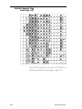
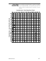
Appendix A - Character References . . . .
Resident Fonts 1-5 . . . . . . . . . . . .
Default Character Map Code Page - 437 .
Dump Mode Character Map . . . . . . .
.
.
.
.
Appendix B - Cash Drawer Kicker Option
Cash Drawer Cable Wiring . . . . . . .
<Esc>p Command - Generate Pulse CDK .
<Esc>u Command - CDK Status . . . . . .
980352-001 Rev.A
.
.
.
.
.
.
.
.
.
.
.
.
.
.
.
.
.
.
.
.
.
.
.
.
.
.
.
.
.
.
.
.
.
.
.
.
.
.
.
.
.
.
.
.
.
.
.
.
.
.
3-106
3-107
3-108
3-109
3-110
3-111
3-112
. . .
. . . .
. . . .
. . . .
A-1
A-1
A-2
A-3
. . . . . . . B-1
. . . . . . . . B-2
. . . . . . . . . B-3
. . . . . . . . . B-4
v
vi
980352-001 Rev.A
Introduction
This section contains information about the basic features, command syntax and terminology
of the EPL2 Programming Language for Zebra's
desktop printers with flash memory architecture. These printers incorporate common programming code sets and architectural features.
The primary operating mode for the printer is
EPL2, a page description language. It is designed to assemble all the elements of the label
prior to printing to speed the printing process.
EPL2 is an ideal language for your labeling and
bar code requirements. The EPL2 is versatile
and is capable of printing a wide range media
and bar codes.
Some printer models also include a legacy
printer compatibility mode, Line Mode. Line
Mode supports our early model EPL programming language - ELP1. A separate manual is
p r o v i d e d f o r L i n e M o d e p r i n ti n g
(p/n 980326-001). See the printer's Software
and Documentation CD with the specific
model's Programmer' Manual button selector or
visit our web site at: www.zebra.com
980352-001 Rev.A
1-1
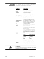
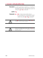
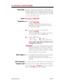
Command The manual uses the following typographic
Conventions conventions to describe commands.
Example
Description
A
Commands (Case Sensitive)
p1,p2,p3
Required parameters
[p1, p2, p3]
Optional parameters
{Choice 1|Choice 2}
Indicates a mandatory choice between two or more items. You
must include one of the items unless all of the items are also enclosed in square brackets.
This text should be →
on one line
The line-continuation character
(→) indicates that code is continued from one line to the next and
should be typed all on one line.
↵
Line feed character.
“NAME”
The name of a form or graphic in
double quote marks.
“DATA”
The text or bar code data in double quote marks.
The (\) character designates that
the character following is a literal
and will encode into the data
field. Refer to the following examples:
To Print
”
“Company”
\
\code\
“PROMPT”
Enter into Data Field
\"
\"Company\"
\\
\\code\\
An ASCII text field that will be
transmitted to the host (via the serial interface) each time this command is executed.
Attention!!
All commands and alpha character command
parameters are case sensitive!
1-2
980352-001 Rev.A
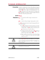
Basic Command Each command consists of one or two ASCII
Syntax (case sensitive) alpha characters to identify the
specific command desired. Some commands
require one or more additional parameters to
supply the printer with sufficient information to
complete the command. Refer to Figure 1- for
the basic command syntax.
Figure 1-1
Command Name
Basic Command
WRITE TEXT
Syntax
A p1,p2,p3,p4,p5,p6,p7,"DATA"↵
Command
Parameters
Command
Specific
Data
Each command line must be terminated with a
Line Feed (LF) character (Dec. 10). Most PC
based systems send CR/LF when the Enter key
is pressed. The Carriage Return (CR) character
is ignored by the printer and cannot be used in
place of LF.
Command Editor One method to create command files is through
an ASCII based text editor. In the DOS environment, MS-DOS EDIT or BRIEF are good
choices. To execute the file, use the editor’s
print command or from the DOS prompt, use
the COPY command to send the file directly to
the printer. An example of the use of the COPY
command is:
COPY “FILENAME.EXT” LPT1↵
or
COPY “FILENAME.EXT” COM1↵
For more information on the use of the COPY
command, refer to your DOS software manual.
Configure the COM port to match the printer’s
serial port setting (typically set to defaults). See
the Y command in section 2 for details.
980352-001 Rev.A
1-3
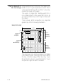
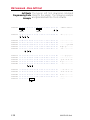
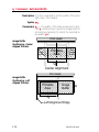
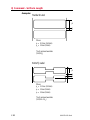
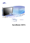
Placing Elements in Image elements are located in the image print
the Print Image buffer on a X-Y grid expressed in dots. The X
value represents the width and the Y value represents the height of the grid.
The point of origin (the starting point) for a
non-rotated object is the upper left corner. As
an object rotates, the point of origin rotates with
the object.
These image buffer properties are depicted
graphically in the following illustration.
Sample Format
"q" dots
x axis
Text
Text
Point of
Origin for
Text Object
Text
y axis (0,0)
Point of
Origin for
BarCode Object
Direction Of Feed
Point of
Origin for
Text Object
Rotated 90°
"Q"
dots
Point of
Origin for
Text Object
Rotated 270°
The minimum non printing margin on all edges
of the label is 1mm. Printing closer than 1mm to
the top or bottom edge of the label may cause
the printer to advance unwanted labels or cause
the printer to go into error condition.
1-4
980352-001 Rev.A
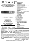
Text (Fonts) The standard EPL2 printer has five (1-5) resident mono-spaced dot fonts. Fonts A-Z and a-z
(upper and lower case alpha characters) are reserved for downloading soft fonts.
First Character of Text String Reference Point
12
D
o
t
s
8 Dots
Character Width
Total Character Width
Inter-character Space
(actually white dots)
Control text height (in horizontal dots) and
width (in vertical dots) with the horizontal and
vertical multipliers. The text is oriented first and
then the A command’s font multipliers are applied.
980352-001 Rev.A
1-5
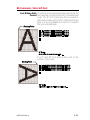
The text is placed into the image buffer. See the
following example.
Horizontal Dots
x axis
y axis (0,0)
Text
Text - No Size Multipliers
Point of
Origin for
V Text Object
e Rotated 90°
r
t
i
c
a
l
2x Horizontal Multiplier
Text
Text
Point of
Origin for
Text Object
Point of
Origin for
Text Object
Point of
Origin for
Text Object
Text
D
o
t
s
Text
2x Vertical Multiplier
Direction Of Feed
Point of Origin
for Text Object
Rotated 270°
The reference point of the first character in a text
string is not affected by the font size multiplier values.
First Character of Text
String Reference Point
2 times
1-6
2 times
980352-001 Rev.A
Bar Codes All bar codes supported by the EPL2 language
have associated industry specifications that the
programmer should be aware of and adhere to.
The programmer needs to consider bar code
features and requirements when choosing and
using a bar code for different applications.
Some of the features and requirements that
need consideration are listed below:
❏Data used by the application are per the bar
code specification (numbers only, alphanumeric, alphanumeric and special characters,
etc.).
❏Minimum and maximum number of characters allowed or required per bar code.
❏Density or magnification of a given bar code
type.
❏White area required around bar codes (the
“Quiet Zone”).
❏The bar code must print within the image
buffer (printable area of the label).
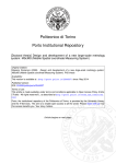
Bar Code Orientation Tip
To help ensure that generated bar codes are readable by the widest variety of bar code readers, print
bar codes in the “Picket Fence” orientation versus
the “Ladder” orientation.
Horizontal Dots
x axis
y axis (0,0)
Height of
Bar Code
Height of
Bar Code
V
e
r
t
i
c
a
l
Picket Fence
Orientation
Ladder
Orientation
D
o
t
s
Direction Of Feed
980352-001 Rev.A
1-7
Programming Graphic elements can interact and the resultant
Sequences Affect image can be affected by other commands.
Graphic Results Structure command sequences to reduce the
chances of unexpected print results. The printer
will process lines, text, boxes and most bar
codes in command sequence. The printer then
processes the printer control processes, counters, variable data, Postnet, and then graphics
last.
1-8
980352-001 Rev.A
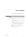
Printer Configuration
This section covers the interpret your printer's
configuration setup and setting basic modes.
Printer AutoSense Use the printer's AutoSense feature to deterFeature mine your printer's configuration and operating
mode. The primary functions that AutoSense
provides are:
❏Adjustment of the Media Sensor in the printer
to the media in use.
❏Programming Mode - Page (EPL2) or Line
(EPL1 emulation) Mode. Note - Line Mode is
not available for all printer models.
❏The printer' serial interface settings.
❏Reports the printer's configuration status including printer options.
980352-001 Rev.A
2-1
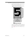
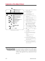
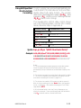
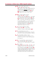
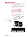
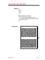
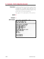
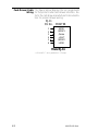
Explanation of the Status Printout
4M03351F 16 V3.18
Serial port:96,N,8,1
Page Mode 200dpi
Image buffer size:0507K
Fmem:000.0K,061.4K avl
Gmem:000K,045K avl
Emem:024K,045K avl
I8,0,001 rY
S4 D00 R128,000 ZT UN
q832 Q1022,029
Option:D,P,C,S
oEw,x,y,z
16 23 31
Date: 10-05-94
Time:01:00:00
Dump Mode Print Sample
A. Printer I.D. code number and firmware
version number.
B. Serial port configuration.
C. Programming Mode
Print head resolution
USB is printed here if installed
D. Print head test pattern.
E. Amount of memory available for the
Image buffer.
F. Amount of memory used and memory
available for Form storage.
G. Amount of memory used and memory
available for Graphics storage.
H. Amount of memory used and memory
available for Soft fonts.
I. Currently selected Character Set (I)
and Image Buffer mode setting (r).
rY = Double Buffering Enabled
rN = Double Buffering Disabled
J. Currently selected Print Speed (S),
Heat Density (D), Reference Point (R),
Print Orientation (Z) and Error Status
(U).
K. Currently selected Form Width (q) and
Length (Q).
L. Current Hardware and Software
Option status .
M. Current AutoSense Through (Gap)
Sensor values. The three numbers
represent;
1. Backing Transparent point
2. Set point
3. Label Transparent point.
N. Current time set in Real Time Clock.
This value will only be displayed if
your printer is equipped with the Real
Time Clock feature.
O. Current date set in Real Time Clock.
This value will only be displayed if
your printer is equipped with the Real
Time Clock feature.
Determining Printer The printer version numbers are a code used to
Firmware Version document product function and the feature
support level of the printer. The latest firmware
version and updates can be obtained from our
web site.
2-2
980352-001 Rev.A
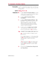
Programming Mode Flash based printers are, by default, configured
Configuration for Page (EPL2) mode operations. The operator must convert the printer to Line Mode prior
to the initial use of Line Mode. This is done via a
hardware select procedure with the Feed button
during printer power-up. See the OEPL1 command (page 3-75) for details on switching between line and page modes via programming.
As of January 2001, the following printers support Line Mode (EPL1 emulation):
· 2443
· 2722
· 2824
· 2844
The Line Mode (and Page Mode) configuration setting is retained after reset has been issued or power
has been cycled.
Manually Setting The Line Mode capable printer utilizes the Feed
Line Mode button during printer power-up to toggle between the printer personality modes, Line and
Page (EPL2).
1. With printer power off, press and hold the
Feed button while turning the printer on, then
release the button when the LED starts blinking
red.
2. When the indicator LED starts flashing green,
immediately press and hold Feed button.
3. Release the Feed button when the LED turns
a steady Amber (orange).
4. Verify printer personality with Dump Mode
printout:. Line Mode or Page Mode (EPL2).
5. Press the Feed button to exit the Dump
Mode.
980352-001 Rev.A
2-3
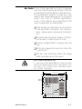
Media Detection Media detection in EPL2 printers is a combination of programming and printer media sensing.
The Q (Set Form Length) and O (Option) commands program the media detection method.
The user must configure the printer for the media type and the (programmed) form or label in
use.
The printer can detect the beginning and end of
the printable area on the media by one of three
methods: Gap, Notch (hole), or Black line. The
Gap method detects the difference in optical
density of a label on a liner from the liner only
with the Transmissive (Gap) sensor. The Notch
method uses the Transmissive sensor to detect a
hole in the media (gap-less labels or tag stock).
The Black line method uses the Reflective sensor to detect a preprinted black line on the media back (for gap-less labels or tag stock).
Printing on continuous media requires programming to control media positioning.
EPL2 printers also support a “Label Dispense”
mode as a printer configuration option (for most
models). The printers use a “Label Taken” sensor to detect the removal of a label.
One or more of these sensors may require user
adjustment or configuration for proper operation. All EPL2 printers have an AutoSense feature to optimize label and label gap detection by
the transmissive (gap) sensor. See the printer’s
user’s manual for printer specific sensor adjustment control.
2-4
980352-001 Rev.A
Command Reference
This section contains a complete listing of all
commands in alphabetical order.
980352-001 Rev.A
3-1
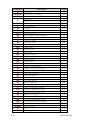
Command
A
AUTOFR
B
b
C
C
D
EI
EK
eR
ES
f
FE
FI
FK
FR
FS
GG
GI
GK
GM
GW
I
JB
JF
LE
LO
LS
LW
M
N
o
oB
oE
oH
oM
oR
oW
O
OEPL1
P
PA
3-2
Description
ASCII Text
Automatic Form Printing
Bar Code
MaxiCode
PDF417
Counter
Cut Immediate
Density
Print Soft Font Info.
Delete Soft Font
User Definable Error Response
Store Soft Font
Cut/Peel Position
End Form Store
Print Form Info.
Delete Form
Retrieve Form
Store Form
Retrieve Graphics
Print Graphics Info.
Delete Graphic
Store Graphic
Direct Graphic Write
Character Set Selection
Disable Top Of Form Backup
Enable Top Of Form Backup
Line Draw Exclusive
Line Draw Black
Line Draw Diagonal
Line Draw White
Memory Allocation
Clear Image Buffer
Cancel Customized Settings
Cancel Customize Bar Code
Line Mode Font Substitution
Macro PDF Offset
Disable Initial Esc Sequence Feed
Character Substitution (Euro)
Customize Bar Code Parameters
Options Select
Set Line Mode
Print
Print Automatic
Page
3-4
3-9
3-11
3-16
3-20
3-27
3-29
3-30
3-33
3-34
3-32
3-35
3-40
3-41
3-42
3-43
3-44
3-45
3-47
3-48
3-49
3-50
3-52
3-53
3-55
3-56
3-57
3-58
3-59
3-60
3-61
3-62
3-63
3-64
3-65
3-66
3-68
3-69
3-71
3-73
3-75
3-76
3-77
980352-001 Rev.A
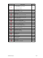
Command
Q
q
r
R
S
TD
TS
TT
U
UA
UB
UE
UF
UG
UI
UM
UN
UP
UQ
US
V
W
xa
X
Y
Z
?
^@
^ee
980352-001 Rev.A
Description
Set Form Length
Transmissive (Gap) Sensor
Black Line Sensor
Continuous Stock
Set Form Width
Set Double Buffer Mode
Set Reference Point
Speed Select
Define Date Layout (& Print Date)
Set Real Time Clock
Define Time Layout (& Print Time)
Print Configuration
Enable Clear Label Counter Mode
Reset Label Counter Mode
External Font Information Inquiry
Form Information Inquiry
Graphic Information Inquiry
Host Prompts/Codepage Inquiry
Codepage & Memory Inquiry
Disable Error Reporting
Codepage & Memory Inquiry/Print
Configuration Inquiry
Enable Error Reporting
Define Variable
Windows Mode
Sense Media
Box Draw
Serial Port Setup
Print Direction
Download Variables
Reset Printer
Status Report - Immediate
Page
3-80
3-78
3-84
3-85
3-86
3-87
3-88
3-89
3-90
3-91
3-92
3-93
3-94
3-95
3-96
3-97
3-98
3-99
3-100
3-101
3-103
3-105
3-106
3-107
3-108
3-109
3-110
3-111
3-112
3-3
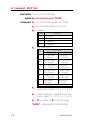
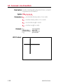
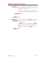
A Command - ASCII Text
Description Prints an ASCII text string.
Syntax Ap1,p2,p3,p4,p5,p6,p7,"DATA"
Parameters p1 = Horizontal start position (X) in dots.
p2 = Vertical start position (Y) in dots.
p3 = Rotation
Value
Description
0
No rotation
1
90 degrees
2
180 degrees
3
270 degrees
p4 = Font selection
Value
Description
203 dpi
300 dpi
1
20.3 cpi, 6 pts,
(8 x 12 dots)
25 cpi, 4 pts,
(12 x 20 dots)
2
16.9 cpi, 7 pts,
(10 x 16 dots)
18.75 cpi, 6 pts,
(16 x 28 dots)
3
14.5 cpi, 10 pts,
(12 x 20 dots)
15 cpi, 8 pts,
(20 x 36 dots)
4
12.7 cpi, 12 pts,
(14 x 24 dots)
12.5 cpi, 10 pts,
(24 x 44 dots)
5
5.6 cpi, 24 pts,
(32 x 48 dots)
6.25 cpi, 21 pts,
(48 x 80 dots)
Reserved for
Soft Fonts
Reserved for
Soft Fonts
A-Z
Fonts 1 - 5 are fixed pitch.
p5 = Horizontal multiplier, expands the text
horizontally. Values: 1, 2, 3, 4, 5, 6, & 8.
p6= Vertical multiplier, expands the text vertically. Values: 1, 2, 3, 4, 5, 6, 7, 8, & 9.
p7 = N for normal or R for reverse image
“DATA” = Represents a fixed data field.
3-4
980352-001 Rev.A
A Command - ASCII Text
The backslash (\) character designates the following character is a literal and will encode into
the data field. Refer to the following examples:
To Print
“
“Company”
\
\code\
Enter into data field
\”
\”Company\”
\\
\\code\\
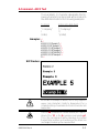
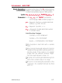
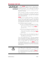
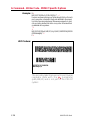
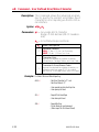
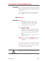
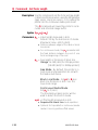
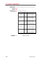
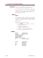
Examples: ¿
N¿
A50,0,0,1,1,1,N,"Example 1"¿
A50,50,0,2,1,1,N,"Example 2"¿
A50,100,0,3,1,1,N,"Example 3"¿
A50,150,0,4,1,1,N,"Example 4"¿
A50,200,0,5,1,1,N,"EXAMPLE 5"¿
A50,300,0,3,2,2,R,"Example 6"¿
P1¿
Will Produce:
As shown in example 5 above, font 5 only supports
upper case characters. Refer to Appendix A for a
complete listing of available fonts and character sets
supported.
HINT
980352-001 Rev.A
Use the LE command to create reverse print text instead of the “R” in the A command parameter p7.
This is the recommend method because it provides
the best size, position and centering of the black line
(rectangle) bordering the reversed text.
3-5
A Command - ASCII Text
Variable Data and The “Data” field can be replaced by or comCounter Functions bined with the following commands:
Vnn= Prints the contents of variable “nn” at
this position where nn is a 2 digit number from 00 to 99. See the V command,
page
Cn= Prints the contents of counter “n” at this
position where n is a one digit number
from 0 to 9. See the C command, page .
Example: A50,0,0,1,1,1,N,"DATA"¿
: Writes Text
A50,50,0,2,1,1,N,V01¿: Writes contents of variable 01
A50,100,0,3,1,1,N,C1¿: Writes contents of counter 1
A50,100,0,3,1,1,N,C1+2¿ : Writes contents of counter 1 plus 2
Data with the RTC The “Data” field can be replaced by or comTime & Date bined with the following variables:
Functions
TT = Prints the current time at this position in
the predefined format. See the TT command for format selection. This variable
is available only if the printer Time &
Date option is installed.
TD = Prints the current date at this position in
the predefined format. See the TD command for format selection. This variable
is available only if the printer Time &
Date option is installed.
Examples: A50,150,0,4,1,1,N,TT↵
A50,200,0,5,1,1,N,TD↵
: Writes current time
: Writes current date
or a combination of several options:
A50,300,0,3,2,2,R,"Deluxe"V01C2"Combo"TDV01TT↵
:Writes the text “Deluxe” followed by the contents of variable 01 followed by the contents of counter 2 followed by the text “Combo” followed by the current date followed by the contents of variable 01
followed by the current time.
3-6
980352-001 Rev.A
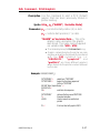
A Command - ASCII TEXT
Simple Expressions An advanced function of the A command allows
in Data Fields addition and subtraction to be performed on
constant and variable values in flash printers.
Syntax Ap1,p2,p3,p4,p5,p6,p7,"DATA"[p8p9p10…]
Parameters For the p1 - p7 and “DATA” parameters See first page of A command, page 3-4.
p8 = Required. Must be a variable data field
number, e.g. V00, V01 etc.
p9 = Required. Operator, + or –
p10 = Required. Variable data field number
or constant value.
Valid Number Ranges:
Constant = 0 to 2147483647
Variable = 0 to 2147483647
Result = -2147483648 to 2147483647
❏The Expression must start with a variable
field.
❏The character field length defined for the first
variable in the expression will be used to format the result. If the result is of a greater
length than the defined character length,
then the result field will contain ‘X’s.
❏A syntax error will be generated during form
store if the constant value is too large.
❏If an error occurs during the evaluation of the
expression, the resultant field will be filled
with ‘X’s.
980352-001 Rev.A
3-7
A Command - Simple Expressions in Data Fields
Example: ¿
FK"1"¿
FK"1"¿
FS"1"¿
V00,10,N,"Enter current mileage"¿
A100,100,0,4,1,1,N,"Current mileage is “V00" miles.”¿
A100,200,0,4,1,1,N,"Change oil at “V00+3000" miles.”¿
FE¿
¿
FK"2"¿
FK"2"¿
FS"2"¿
V00,10,N,"Enter current mileage."¿
V01,10,N,"Enter interval mileage."¿
A100,100,0,4,1,1,N,"Current mileage is “V00" miles.”¿
A100,200,0,4,1,1,N,"Mileage interval is “V01" miles.”¿
A100,200,0,4,1,1,N,"Change oil at “V00+V01" miles.”¿
FE¿
¿
FK"3"¿
FK"3"¿
FS"3"¿
V00,10,N,"Enter value 1."¿
V01,10,N,"Enter value 2."¿
V02,10,N,"Enter value 3."¿
A100,200,0,4,1,1,N,"Answer: “V01+123+V00-10-V02¿
FE¿
Asian Character Font The flash based printers support three Asian
Sets language sets. Asian language support is an optional feature and requires a special version of
the printer (PCBA) to support the large Asian
character sets.
The Asian character maps and special features
of the A command that support the character
sets can be found on our Internet site or from
CD ROM. Click on the code page reference (in
the electronic manual version) to display the
Addendum and its code pages.
Chinese Addendum - P/N 980095-061
Japanese Addendum - P/N 980095-071
Korean Addendum - P/N 980095-081
3-8
980352-001 Rev.A
AUTOFR Command - Automatic Form Printing
Description This special form process allows you to detach
the printer from the computer and print in a
standalone mode. The EPL2 printer reserves
the form name AUTOFR to allow the printer to
automatically start a form when the printer is initialized power-up. This feature can be used in
many ways:.
· Feed a single label in peel mode and print
multiple labels set to the number of labels on
the roll.
· Have a form with a variable and enter the
variable with a scanner, terminal, weight
scale, circuit analyzer or any other device capable of sending ASCII character data.
Using AUTOFR Download a form to the printer with the name
AUTOFR.
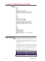
Example: ¿
:Line Feed to initialize the printer
:Form Kill (delete any existing AUTOFR)
:Form Save (save file from here to FE at
: the bottom)
V00,8,L,""¿
:Variable field definition
Q254,20¿
:Label height followed by gap width
S2¿
:Speed (2ips)
D7¿
:Density setting
ZB¿
:Print direction (ZT flips it 180 degrees)
A340,20,0,4,1,2,N,"QUANTITY"¿
:Fixed text line
B265,75,0,3,2,4,101,B,V00¿ :Bar code definition
PA1¿
:Print 1 label Automatically *
FE¿
:Form End (Line Feed)
FK"AUTOFR"¿
FS"AUTOFR"¿
* - If using the CAL TOOLS, CAL WIN, etc. programs to generate label files (files with .ejf extensions), then the PA command
must be added manually by editing the .ejf file.
980352-001 Rev.A
3-9
AUTOFR - Automatic Form Printing Feature
AUTOFR treats any incoming data as a variable intended for printing. This means if you send the
printer a memory partition command, the label will
print, if you send a delete command - the label will
print! So, while you are testing AUTOFR it is best to
use another name for the form. Once you are satisfied with the form, rename it AUTOFR before you
download it. There is no need to specify a file extension.
Isolating Data From Place the printer in the diagnostic dump mode
the Input Device and send from your data input device. All characters the device sends will be printed on the label.
· If nothing prints, nothing is arriving - check
pin-outs and serial settings.
Disabling AUTOFR Send a XOFF data character (13 hex. or ASCII
19) or a NUL (00 hex. or ASCII 0) to the printer.
The form may now be deleted from the printer.
Removing AUTOFR The programmer must send a Delete Form - FK
command to the printer after disabling
AUTOFR.
Example: FK"AUTOFR"¿
FK"AUTOFR"¿
3-10
980352-001 Rev.A
B Command - Bar Code
Description Use this command to print standard bar codes.
Syntax Bp1,p2,p3,p4,p5,p6,p7,p8,"DATA"
Parameters p1 = Horizontal start position (X) in dots
p2 = Vertical start position (Y) in dots.
p3 = Rotation
Value
0
Description
No rotation
1
90 degrees
2
180 degrees
3
270 degrees
p4 = Bar Code selection (see Table 2-1 on
next page).
p5 = Narrow bar width in dots. (see Table
2-1 on next page).
p6 = Wide bar width in dots.
Acceptable values are 2-30.
p7 = Bar code height in dots.
p8 = Print human readable code.
Values: B=yes or N=no.
“DATA” = Represents a fixed data field. The
data in this field must comply with the selected
bar code’s specified format.
The backslash (\) character designates the following character is a literal and will encode into
the data field. Refer to the following examples:
To Print
“
“Company”
\
\code\
980352-001 Rev.A
Enter into data field
\”
\”Company\”
\\
\\code\\
3-11
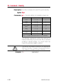
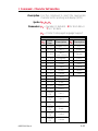
B Command - Bar Code
Bar Codes
Description
Code 39 std. or extended
Code 39 with check digit
P4
P5
Value Value
3
1-10
3C
1-10
Code 93
9
1-10
Code 128 UCC
Serial Shipping Container Code
0
1-10
Code 128 auto A, B, C modes
1
1-10
Code 128 mode A
1A
1-10
Code 128 mode B
1B
1-10
Code 128 mode C
1C
1-10
K
1-10
EAN8
E80
2-4
EAN8 2 digit add-on
E82
2-4
EAN8 5 digit add-on
E85
2-4
EAN13
E30
2-4
EAN13 2 digit add-on
E32
2-4
EAN13 5 digit add-on
E35
2-4
German Post Code
2G
3-4
2
1-10
Interleaved 2 of 5 with mod 10 check digit
2C
1-10
Interleaved 2 of 5 with human readable
check digit
2D
1-10
Postnet 5, 9, 11 & 13 digit
P
—
Japanese Postnet
J
—
UCC/EAN 128*
1E
1-10
UPC A
UA0
2-4
UPC A 2 digit add-on
UA2
2-4
UPC A 5 digit add-on
UA5
2-4
UPC E
UE0
2-4
UPC E 2 digit add-on
UE2
2-4
UPC E 5 digit add-on
UE5
2-4
UPC Interleaved 2 of 5
2U
1-10
Plessey (MSI-1) with mod. 10 check digit
L
—
MSI-3 with mod. 10 check digit
M
—
Codabar
Interleaved 2 of 5
* - Use ASCII 06 to delimit variable length fields.
3-12
980352-001 Rev.A
B Command - Bar Code
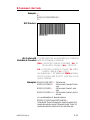
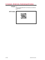
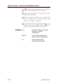
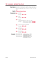
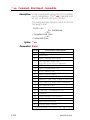
Example: ¿
N¿
B10,10,0,3,3,7,200,B,"998152-001"¿
P1¿
Will Produce:
Bar Codes with The data field can be replaced by or combined
Variables & Counters with the following commands:
Vnn =Prints the contents of variable “nn” at
this position. Range of nn = 00 to 99.
Cn =Prints the contents of counter “n” at this
position. Range of n = 0 to 9
See Appendix C for additional Data parameters for printers with the RTC (real time clock)
option installed.
Examples: B50,0,0,3,1,2,50,B,"DATA"¿ : Writes bar code
B50,50,0,3,1,2,50,N,V01¿
: Writes contents of variable 01 as bar
: code
B50,50,0,3,1,2,50,N,C1¿
: Writes contents of counter 1 as bar
: code
B50,50,0,3,1,2,50,N,C1+2¿ : Writes contents of counter 1 plus2 as
: bar code
or a combination of several options:
B50,300,0,3,1,2,50,B,"Deluxe"V01C2"Combo"V01¿
:Writes the text “Deluxe” followed by the contents of variable 01 followed by the contents of counter 2 followed by the text “Combo” followed by the contents of variable 01 all as a code 39 bar code.
980352-001 Rev.A
3-13
B Command - Bar Code
Data with the RTC The “Data” field can be replaced by or comTime & Date bined with the following variables:
Functions
TT = Prints the current time at this position in
the predefined format. See the TT command for format selection. This variable
is available only if the printer Time &
Date option is installed.
TD =Prints the current date at this position in
the predefined format. See the TD command
for format selection. This variable is available
only if the printer Time & Date option is installed.
Some bar code formats will not support date names
or the date or time delimiters used by the printer to
separate
Code 128 Bar Code The printer supports code 128 function control
Function Characters characters (FCN#). Multiple FCN#s, TTs, TDs
and “DATA” strings can be concatenated, allowing them to be inserted anywhere within the
symbol.
FCN2, FCN3 and FCN4 are illegal in code
128 mode C (p4 = 1C) and will result in a syntax error.
Please refer to the Code 128 standard for a description of function characters FNC1 through
FNC3.
“Standard” Code 128 can encode all 128 standard ASCII characters (0-127). Function character FCN4 provides a means of also encoding
extended ASCII characters (128-255). It directs
the reader to add 128 to the value of each affected character before transmitting it.
Two consecutive FCN4s toggle between standard and extended ASCII mode for all succeeding data characters (until the end of the symbol,
or until another pair of s is encountered). This is
referred to as latching into extended ASCII
mode or latching into standard ASCII mode.
3-14
980352-001 Rev.A
B Command - Bar Code
Code 128 Bar Code A single FCN4 toggles between standard and
Function Characters extended ASCII mode for only a single follow(continued) ing data character. This is referred to as shifting
into extended ASCII mode or shifting into standard ASCII mode.
Both code sets A and B are needed to represent
the entire extended ASCII character set, just as
both sets are needed to represent the standard
ASCII character set.
FCN4s can be inserted manually, if necessary
or desired, by following the syntax described
above. The printer will, however, insert them
automatically if extended ASCII characters are
encountered in the DATA. It will do so in the
most efficient manner possible:
· If up to 4 contiguous extended ASCII characters are encountered, it will shift into extended
ASCII mode by inserting a single FCN4 before each one;
· If 5 or more contiguous extended ASCII char-
acters are encountered, it will latch into extended ASCII mode by inserting two FCN4s
before them.
· While latched into extended ASCII mode, it
will apply the same rules if standard ASCII
characters are encountered.
Thus, the preferred way to encode extended
ASCII characters is to simply embed them in the
DATA and let the printer manage the encoding
task. For best results, the code set should also
not be specified (i.e., p4 = 1). FCN4 s should
be manually inserted only in systems where extended ASCII characters cannot be transmitted
to the printer.
it is illegal to mix automatic and manual modes
within the data for a single symbol; i.e., an extended
ASCII character encountered in the data after an will
be considered a syntax error. Likewise, an FCN4 after an extended ASCII character will also be considered a syntax error.
980352-001 Rev.A
3-15
b Command - 2D Bar Code - MaxiCode Specific Options
Description Use this command to generate MaxiCode bar
code symbols with a single command. The
printer will automatically interpret and encode
data into MaxiCode symbols for data modes 2,
3, 4, and 6. Up to eight symbols can be linked.
Syntax bp1,p2,p3,[p4,][p5,]“DATA”
Parameters p1 = Horizontal start position (X) in dots
p2 = Vertical start position (Y) in dots
p3 = M - Must be "M" for MaxiCode
p4 = Mode Selection
Value
Not Used
M2
M3
m4
m6
Description
Automatic Selection Mode 2 or 3
Mode 2
Mode 3
Mode 4
Mode 6
1. If p4 (Mx) is not used, the printer will use the
following rules to automatically format the
“DATA” parameter. If the postal code (third
parameter, PC) in the “DATA” is:
· All numeric characters, the printer will automatically select Mode 2.
· Alpha only or alpha-numeric character combinations will set the printer to Mode 3.
· Not used, the printer automatically selects
Mode 3.
2. If p4 value is “M2 or M3”, the printer will use
the following rules to format the “Data” parameter:
· In Mode 2 - If a non-numeric character is en-
tered in the Postal Code “Data” parameter
field, then the MaxiCode bar code will not print.
· In Mode 3 – If the Postal Code “Data” field
exceed 6 characters, then the additional characters will be truncated from the bar code field.
3-16
980352-001 Rev.A
b Command - 2D Bar Code - MaxiCode Specific Options
p5= x,y
Associated MaxiCode symbol numbering
where:
x = Symbol Number of
y = Total Number of Associated Symbols
Default: Not used
Range: 1-8 for both x or y
”DATA”= Mode Dependent Data Format
Mode dependent data is bounded by quotation
marks. Maximum of 2 KBytes of data.
Mode
2&3
4&6
Data Format
“cl,co,pc,lpm”
“lpm”
cl = Class Code (3 digits required)
co = Country Code (3 digits required)
Mode 2 = Numeric Characters
Mode 3 = International Characters
(up to 6 characters)
pc = Postal Code
Mode 2 = 5 or 9 characters
(All Numeric, including USA
Postal ZIP 5 or 9 char.)
For less than 9 characters, the
printer will pad the field with 0’s.
Mode 3 (International)= Any
alphanumeric character
(up to 6 characters)
lpm = Low priority message (data)
ASCII printable characters (up to
84 characters per symbol), any
256 character map.
The programmer should rely on the symbology's
specification to insure format compliance and
proper implementation. See the AIM web site
for specifications at:
http://www.aimi.org/
980352-001 Rev.A
3-17
b Command - 2D Bar Code - MaxiCode Specific Options
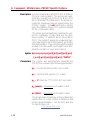
Example: N¿
b20,20,M,"300,840,93065,1692,This is MaxiCode, but not MaxiCode
formatted data"¿
P1¿
Will Produce:
3-18
980352-001 Rev.A
Using AIM Specified The EPL printer can use and automatically deMaxiCode Data code the AIM ITS (International Technical StanFormatting dards) MaxiCode data format. The printer
detects the message/start header ([)>RS), field
separator (GS), and the end of message marker
(RS EOT) data control strings.
The hexadecimal (ASCII) data control strings
are in the following table. See the EPL2 dump
mode character map in Appendix A.
Control String
Hexadecimal Code
Message/Start Header
[ ) > RS
5B 29 3E 1E
Field Separator
GS
1D
End Of Message Marker
RS EOT
1E 04
Syntax bp1,p2,M,p4 “[AIM MaxiCode Data]”
Example b20,400,M,m2”001,840,93065,1692,[)>RS
01GS98XXXZZFDAAFGSSHIPGS309GSGS1/1GS10GS
NGSGSCAMARILLOGSCAGSRSEOT!!!!!!!!!!!!!!!!!!!!!!!”
¿
Notes:
1) This programming example represents actual data used to
format a single AIM compliant MaxiCode symbol as programmed by a major international and domestic shipping company.
2) The shipper has explicitly set the MaxiCode symbol for Mode
2. This can be omitted by the programmer and the printer will
auto-select the mode per the rules on page 3-16.
3) The shipper has used the "!" character to pad the symbol's
data. A scanner reads back all the "Data" within the quotation
marks, including the "!" characters following the End Of Message Marker (EOT).
4) All of the data fields in the Low Priority Message are not
used in the example. Some are left empty with the field delimiting GS character used as a format field holder.
980352-001 Rev.A
3-19
b Command - 2D Bar Code - PDF417 Specific Options
Description Use this command to print PDF 417 and Macro
PDF bar code symbols. The printer will automatically change from PDF417 to Macro PDF
bar code mode if the data sent to the printer exceeds the maximum amount supported by the
PDF417 symbol. The oH command is used to
place the addition Macro PDF symbols needed
for the continuation data.
The printer will automatically optimize the symbol for readability of data (and use the minimum number of symbols when using Macro
PDF). The symbol's geometry is adjusted (typically reducing the size of the symbol) per the defined parameters. The printer will use the largest
module size (bar width and height) and minimize the number of rows and columns.
Syntax bp1,p2,p3,p4,p5[,p6][,p7][,p8][,p9][,p10]
[,p11][,p12][,p13][,p14][,p15],”DATA”
Parameters The printer will automatically generate the
PDF417 bar code using the following parameters.
p1 = Horizontal start position (X) in dots
p2 = Vertical start position (Y) in dots
p3 = P - Must be "P" for PDF 417 bar codes
p4 (www) =maximum print width in dots
p5 (hhh) = maximum print height in dots
The programmer should rely on the symbology's
specification to insure format compliance and
proper implementation. See the AIM web site
for specifications at:
http://www.aimi.org/
3-20
980352-001 Rev.A
b Command - 2D Bar Code - PDF417 Specific Options
The following parameters may be omitted and default values will automatically be inserted. Each parameter value (data string) must be proceeded by its
associated command prefix character.
p6 (s) = sets error correction level
Error Correction codewords per symbol
Values: s1 - s8
If level is not specified, a level will automatically be assigned as per the following table:
EC level
0
1
2
3
4
5
6
7
8
EC Codewords
2
4
8
16
32
64
128
256
512
Auto Select Level
—
0-31
32-63
64-127
128-255
256-511
512-928
—
—
p7 (c) = selects data compression method
Values: 0 or 1, default is 0
c0 = Auto-encoding
c1 = Binary mode
Data Type
Text
Numeric
Binary
Compression (Byte by Byte)
2 Characters per codeword
2.93 Characters per codeword
1.2 Bytes per codeword
p8 (pxxx,yyy,mm) = print human readable
This parameter is a non-standard implementor of the PDF417 and is only
recommended for troubleshooting purposes.
Additional variables:
p ="p" - parameter identifier
xxx = horizontal start location
yyy = vertical start location
mm = maximum characters per line
980352-001 Rev.A
3-21
b Command - 2D Bar Code - PDF417 Specific Options
p9 (f) = Bar code origin point
Values: 0 or 1, Default is 1
f1- Center of bar code as defined by the
automatically adjusted symbol size, i.e.
width and height. Parameters p4 and
p5 values are maximum values only.
f0- Upper left corner of bar code.
p10 (x) - module width (in dots)
Values: 2 - 9 (i.e. x2-x9)
Default: Auto selects 6 (dots). Tests data
with maximum size limit set by p4 and
p5 and then the other optional parameters. The printer automatically reduces
the module width in one dot increments
until the data fits within the symbols
maximum dimensions (and other applied parameters) or until 3 dots has
failed, then reports an error.
p11 (y) - set bar height (in dots)
Range: 4 - 99 (i.e. y4-y99)
Default: 4 times module width (p10)
p12 (r) - maximum row count
Maximum limit for the number of rows to
be used for auto selecting symbol features.
p13 (l) - maximum column count
Maximum limit for the number of columns to be used for auto selecting symbol features.
p14 (t) - truncated flag - legal values are:
0 = not truncated, 1= truncated
See the PDF 417 specification for details.
p15 (o) - rotation
Values: 0= 0º, 1= 90º, 2= 180º, 3= 270º
Settings of 90° & 270° will cause the symbols maximum height (p4) and width (p5)
values to transpose when automatically calculating and generating the symbol, i.e. the
height would affect column dimensions
and width would affect row dimensions.
3-22
980352-001 Rev.A
b Command - 2D Bar Code - PDF417 Specific Options
"DATA" = ASCII data or Binary data bytes
Represents a fixed data field.
The backslash (\) character designates the following character is a literal and will encode into
the data field. Refer to the following examples:
To Print
Enter into data field
“
\”
“Company”
\”Company\”
\
\\
\code\
\\code\\
¿
\¿
PDF417: General A PDF417 symbol is organized into minimum
Information of 3 to a maximum of 90 rows and a minimum
of 5 to a maximum of 34 columns of
codewords.
Each codeword is 17 modules wide. There are 4
bars and 4 spaces per codeword.
Multiply the module width (in dots, p10) by 17
to get the codeword width.
Multiple the module height (in dots, p11) by the
number of rows to get the symbol height.
Four of the codewords in each row are start,
stop and two row indicators. The remaining
codewords are referred to as the data region
and contain symbol overhead and compacted
data.
There can be no more than 928 codewords in
the data region. All combinations of rows
and columns are not legal; 90 rows times 30
columns would produce a data region of 2700
codewords which exceeds the 928 codeword
maximum per symbol. See the following table
(on the next page) that shows the maximum
number of rows and the resulting number of
codewords in the data region for each column
count.
980352-001 Rev.A
3-23
b Command - 2D Bar Code - PDF417 Specific Options
PDF417
Symbol Geometry
3-24
Columns
Maximum Rows
Codewords
5
90
90
6
90
180
7
90
270
8
90
360
9
90
450
10
90
540
11
90
630
12
90
720
13
90
810
14
90
900
15
84
924
16
77
924
17
71
923
18
66
924
19
61
915
20
58
928
21
54
918
22
51
918
23
48
912
24
46
920
25
44
924
26
42
924
27
40
920
28
38
912
29
37
925
30
35
910
31
34
918
32
33
924
33
32
928
34
30
900
980352-001 Rev.A
b Command - 2D Bar Code - PDF417 Specific Options
Automatic PDF 417 The printer automatically tests and changes the
Bar Code Generation PDF 417 bar code geometry to maximize the
readability of the bar code for a given maximum
height and width, specified by p4 and p5.
The printer tests the PDF 417 parameters in this
order for a given data string (error correction
and compression included):
1. Module width p10 (for codeword width)
2. Symbol width p4
3. Symbol column maximum p13
4. Module height p11
5. Symbol height p5
6. Symbol row maximum p12
The printer will start with the maximum value
(default or explicit) for these parameters. The
printer reduces these values to get the module
width and height to maximize readability.
980352-001 Rev.A
3-25
b Command - 2D Bar Code - PDF417 Specific Options
Example: N¿
b80,100,P,700,600,x2,y7,l100,r100,f0,s5," \ ¿
Fourscore and seven years ago our fathers brought forth on this continent a new nation, conceived in liberty and dedicated to the proposition that all men are created equal. Now we are engaged in a great
civil war, testing whether that nation or any nation so conceived and
so dedicated can long endure.
"¿
¿
b80,200,P,400,300,p40,440,20,f1,x3,y10,r60,l5,"ABCDEFGHIJK12345
67890abcdefghijk"¿
P¿
Will Produce:
The second symbol has been set to print human
readable data with the p 8 parameter
(p40,440,20) and is not part of the PDF417
symbol.
3-26
980352-001 Rev.A
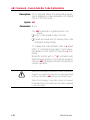
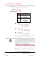
C Command - Counter
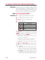
Description The counter (C) command defines one of 10
automatic counters used in consecutive numbering applications (i.e. serial numbers). Counters must be defined after variables.
For Numeric Serialization Only. The counter
function does not support Alpha or Alpha-Numeric
Serialization.
Syntax Cp1, p2, p3, p4, “[-]PROMPT”
Parameters p1 = Counter number.
Range: 0 to 9
p2 = Maximum number of digits for the counter.
Range: 1 to 29
p3 = Field Justification.
L = Left
R = Right
C = Center
N = No Justification
p4 = Step Value. + or - sign followed by a
single digit of 1 - 9. Using a step value of
+0 allows the counter to be used as an
additional variable data field.
“PROMPT”= An ASCII text field that will be
transmitted to the KDU or host (via the
serial interface) each time the command
is executed. Typically used to request the
operator to enter a starting counter value.
KDU Prompt [-] = Having the first character of the prompt
a single minus sign will cause the
Options
prompt to display only once after form
retrieval.
980352-001 Rev.A
3-27
C Command - Counter
The C command is used in forms that require sequential numbering. When initializing counters,
they must be defined in order (e.g. C0 first, C1
second...).
Field justification (p3) affects the printing of
counter data. When L, R or C are selected, the
counter field is the width of p2 value. Data will
justify within the counter (p2) field per the selected p3. The N parameter will print the minimum number of characters. See programming
example 13 in Appendix H.
To print the contents of the counter, the counter
number is referenced in the “DATA” field of the
A (ASCII text) or B (Bar Code) commands.
If the starting value of a counter is “1", then no leading zero padding will be added. If the starting value is
“01”, then the counter will be padded, up to the
maximum number of digits (p2), with zeros.
Example: C0,10,L,+1,"-Enter Serial Number:"¿
Saving and
Protecting
Consecutive
Numbers in
Nonvolatile Memory
This feature is useful when the counter field represents a serial number (or others types of numbers) that should never be repeated. This
feature allows for automatic retrieval and incrementing (or decrementing) of the previous
counter value used every time a form is retrieved (and printed).
By placing one minus sign as the first character
of the prompt, the prompt will appear only once
after the form is retrieved, thereby protecting
the integrity of the data.
Single Digit Add or subtract a single digit from the recalled
Summation with counter value in a form. If form recalled counter
Counters C0 had a value of 3, then processing C0+1
would yield a value of 4 and C0-2 would yield a
value of 1.
3-28
980352-001 Rev.A
C Command - Cut Immediate
Description: This command allows the printer to initiate an
immediate media cut without a form print operation. The printer must have the cutter option
installed.
❏The C command – Cut Immediate can not
be used inside of a form.
❏The initial character C in a command string is
used for both the Cut Immediate (C) and
Counter Conmmand function (Cp1) which
can only be used within a form. The Cut Immediate Command (C) can not be used in a
form.
❏The C command – Cut Immediate can not be
used with the KDU.
Syntax: C
Parameters: None
Example: C¿
Only cut label liner (backing) or tag stock. Label adhesive will built up on the cutter blade and cause the
cutter to operate poorly or jam if the labels are cut
along with the label liner.
Use the C command - Cut Immediate 5 times without
media loaded, to perform a self cleaning of the cutter
blade.
980352-001 Rev.A
3-29
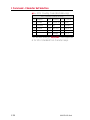
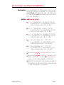
D Command - Density
Description Use this command to select the print density.
Syntax Dp1
Parameters p1 = Density setting. Acceptable values are:
Model
Acceptable Values1 Default Value
2722
0 - 15
7
2742
0 - 15
7
3742
0 - 15
7
2443 (Orion)
0 - 15
10
2824
0 - 15
7
2844
0 - 15
10
Hx-146
0 - 15
7
2746
0 - 15
7
2684 (Strata)
0 - 15
7
Note 1: 0 is the lightest print and 15 is the darkest.
The density command controls the amount of
heat produced by the print head. More heat will
produce a darker image. Too much heat can
cause the printed image to distort.
The density and speed commands can dramatically
affect print quality. Changes in the speed setting typically require a change to the print density.
Example: D5¿
3-30
: selects density 5
980352-001 Rev.A
dump Command - Enable Dump Mode
Description This command allows the advanced programmer to force a user diagnostic “data dump”
mode. Sending the dump command to the
printer allows the programmer to compare actual data sent to printer with the host program.
Send data to the printer after the dump command has been issued to evaluate program and
printer control data. The printer will process all
data bytes into ASCII character data , range
0-255 decimal (00-FF hexadecimal).
Press the printer’s Feed button until “Out of
Dump” is printed or power cycle the printer to
terminate the dump mode.
Syntax dump
Parameters None
Use the “Dump Mode” character map in Appendix A
of the EPL2 programmer’s manual to interpret the
dump mode data (characters printed on the labels)
back into ASCII data.
Graphics data dump may be large and require multiple labels to print.
Set the image buffer width with the q command to
match the media width prior to issuing the dump
command.
Press the Feed button to view dump data that exceeds a single label’s print area. Repeat to view more
dump data.
Pressing the Feed button after the dump data is finished printing will cause the printer to exit the dump
mode.
Example: dump¿
980352-001 Rev.A
3-31
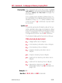
eR Command - User Defined Error/Status Character
Description: This command allows the advanced programmer to specify the printer's error/status report
character for error reporting via the RS-232 serial interface.
Syntax: eRp1,p2
Parameters: p1 = Any single ASCII character
Range: 0-255 decimal (00-FF hexadecimal)
p2 = Error/Status Response Mode
p2
Mode Descriptions
0
Standard (default):
XON (17 dec. / 11 hex.) on Recovery
XOFF (19 dec. / 13 hex.) on Error
1
Character Only:
Reports the selected error/status character
followed by a Carriage Return and Line Feed.
2
Character & Error/Status Code:
Reports the selected error/status character, error/status code (see page 3-112 for codes),
and then by a Carriage Return and Line Feed.
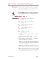
Example: For Mode 2 Error and Status Reporting:
eR$,2¿
: Sets Error Character to "$" and
: Sets Error Mode to "2".
: User operates and prints with printer.
: User opens print head.
$11¿
: Reports Print Head Open
: User closes print head
$00¿
3-32
: Reports No Error
: Printer Ready for next command.
: (Status report for Print Head Closed)
980352-001 Rev.A
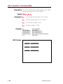
EI Command - Print Soft Font Information
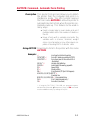
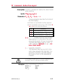
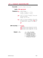
Description This command will cause the printer to print a
list of all soft fonts that are stored in memory.
Syntax EI¿
Soft fonts can be downloaded to and deleted from
the printer from the Soft Font Downloader Utility,
CAL Tools or CAL3.
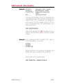
Example: EI¿
:prints soft font list
Will Produce:
980352-001 Rev.A
3-33
EK Command - Delete Soft Font
Description This command is used to delete soft fonts from
memory.
Soft fonts can be downloaded to and deleted from
the printer from the Soft Font Downloader Utility,
CAL Tools or CAL3.
Syntax EK {“FONTNAME”|"*"}
Parameters “FONTNAME” = By entering the name of a
font, that font will be deleted from memory.
“*” = By including an “*” (wild card), ALL
fonts will be deleted from memory.
Example: EK"A"¿
EK"*"¿
3-34
:deletes font “A”
:deletes all fonts
980352-001 Rev.A
ES Command - Store Soft Font
Description This command is used to download and store
soft fonts in memory.
Soft fonts can be downloaded to and deleted from
the printer from the Soft Font Downloader Utility,
CAL Tools or CAL3.
Syntax ES"FONTNAME"p1p2p3a1b1c1“DATA1”a
2b2c2“DATA2” ... anbncn“DATAn”
Parameters “FONTNAME” = One letter font name
Range: a-z, Lower Case
· Lower Case named fonts minimize soft font
memory usage to only store fonts downloaded and have 256 character limit.
The following use hexadecimal
coding for parameter values.
p 1:
Number of characters to be downloaded
Range: 00 - FF hex. (0-255 decimal)
for 1 to 256 fonts per soft font set.
p 2:
Character Rotation
p3 :
· 00 hex. = 0 and 180 degrees
· 01 hex. = 90 and 270 degrees (clockwise)
· 02 hex. = Both 0 and 180 degree rotation
pair and the 90 and 270 degree rotation pair
Font Height
Range: 00 to FF hex.
Measured in dots and expressed as a
hexadecimal number, i.e. 1B hex. = 27
dots
Font height includes accentors and dissenters of characters and need to fit in
the character cell
· 203 dpi printers =
256 dots = 1.26 inches = 32.03 mm
· 300 dpi printers = 00 to FF hex.
256 dots = 0.85 inches = 21.67 mm
980352-001 Rev.A
3-35
ES Command - Store Soft Font
a1:
(1st) Download Character (map position)
Range: 00 to FF hex.
b 1:
(1st) Spacing To Next Print Character
Downloaded character’s next printed
character position in dots, i.e. Character
tracking - the space between characters.
Must be greater than or equal to the
character width, see parameter c1. Dots
in a decimal number converted to a
hexadecimal number.
Range: 00 to FF hex.
c 1:
(1st) Downloaded Character’s Width
Dots in a decimal number converted to
a hexadecimal number.
Range: 00 to FF hex.
“DATA1” : (1st) Character Bitmap
p3 × c1 = bit map data (in bytes)
Data is received in bytes, on a line by line
basis. The font character’s 0,0 cell map
position is in the top left corner of the map
as viewed in the 0 degree rotation. See
the examples on the following pages.
a 2:
(2nd) Download Character (map position)
b2:
(2nd) Spacing To Next Print Character
c 2:
(2nd) Downloaded Character’s Width
“DATA2” : (2nd) Character Bitmap
p3 × c2 bytes = bit map data
Repeat for each character until the last character in the set is downloaded.
an: (Last) Download Character (map position)
bn: (Last) Spacing To Next Print Character
c n:
(Last) Downloaded Character’s Width
“DATAn” : Character Bitmap
p3 × cn bytes = bit map data
3-36
980352-001 Rev.A
ES Command - Store Soft Font
For fonts with the rotation parameter set
for “both” (p2 = 02 hex.):
Repeat the individual font character download
for each 90° rotated character from the start of
the character set until the last rotated character
in the set is downloaded.
a1-90° b1-90° c1-90° “DATA1-90°”
a2-90° b2-90° c2-90° “DATA2-90°”
a3-90° b3-90° c3-90° “DATA3-90°”
an-90° : (Last) Download Character
bn-90° : (Last) Spacing To Next Print Character
cn-90° : (Last) Downloaded Character’s Width
“DATAn-90°” : Character Bitmap
p3 × cn bytes = bit map data
The number of individual character
maps downloaded will be double the
characters in the font set (p1).
Reference Point
Example of
Measuring Soft Font
Size
10 Dots
12
D
o
t
s
8 Dots
Inter-character Space
(actually white dots)
Parameter Dots Data Entered as Hexadecimal
980352-001 Rev.A
p3
12
0C hex.
b
10
0A hex.
c
8
08 hex.
3-37
ES Command - Store Soft Font
Soft Fonts The typical soft font download command
Programming Code strings to the printer. The following example
Example was generated with the CAL3 software.
00000000
0D 0A 45 4B 22 61 22 0D 0A 45 53 22 61 22 03 00
CR & LF
CR & LF
00000010
p1
p2
1A 41 17 03 00 7C 00 00 7C 00 00 7C 00 00 EE 00
p3
a1
b1
..EK"a"..ES"a"..
.A...|..|..|....
c1
00000020
00000030
00 EE 00 01 EF 00 01 C7 00 01 C7 00 03 83 80 03
83 80 07 83 C0 07 01 C0 07 01 C0 0E 00 E0 0F FF
................
................
00000040
00000050
00000060
E0 0F FF E0 1F FF F0 1C 00 70 3C 00 78 38 00 38
38 00 38 70 00 1C 70 00 1C F0 00 1E E0 00 0E 00
00 00 42 17 03 1F FF 00 1F FF C0 1F FF E0 1C 01
.........p<.x8.8
8.8p..p.........
..B.............
a2
b2
c2
00000070
00000080
00000090
E0 1C 00 F0 1C 00 70 1C 00 70 1C 00 70 1C 00 E0
1C 01 E0 1F FF C0 1F FF C0 1F FF E0 1C 00 F0 1C
00 70 1C 00 38 1C 00 38 1C 00 38 1C 00 38 1C 00
......p..p..p...
................
.p..8..8..8..8..
000000A0
000000B0
38 1C 00 70 1C 00 F0 1F FF E0 1F FF C0 1F FF 00
00 00 00 43 19 03 00 7F 00 01 FF C0 03 FF E0 07
8..p............
...C............
a3
b3
c3
000000C0
C1 F0 0F 00 78 1E 00 38 1C 00 3C 1C 00 18 3C 00
....x..8..<...<.
000000D0
000000E0
000000F0
00 38 00 00 38 00 00 38 00 00 38 00 00 38 00 00
38 00 00 38 00 00 1C 00 0C 1C 00 0E 1C 00 1C 0E
00 3C 0F 00 7C 07 C0 F8 03 FF F0 01 FF E0 00 7F
.8..8..8..8..8..
8..8............
.<..|...........
00000100
80 00 00 00 0D 0A
......
CR & LF
3-38
980352-001 Rev.A
ES Command - Store Soft Font
Font Bitmap Data The black and white bitmap that represents the
Format font must be converted into ASCII hexadecimal
code. The 0° font format has dot converted to
data bytes reading from left to right and the last
byte in a line is padded with zeros to complete
the line and data byte.
The 0° and 90° font data is then sent to the
printer in line order.
980352-001 Rev.A
3-39
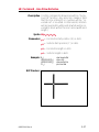
f Command - Cut Position
Description Use this command on an individual printer to
provide precision cut placement.
· Compensate sensor to cutter position differences on a printer by printer basis.
· Fine-tune cut position to compensate for differences in media.
Syntax fp1
Parameters p1 = Cut position index measured in dots.
Acceptable values: 070 to 130. The default value is 100.
When using the label liner cutter option, the
printer will advance each printed label to the
appropriate programmed offset cut position,
between labels, before cutting. Due to media
differences, the printer may not accurately
position the labels before cutting, causing the
cutter to cut the label instead of the liner.
The printer’s cutter is not designed to cut labels. Labels have adhesive that may interfere with the
proper operation of the cutter.
Only cut label liner and tag stock and do not exceed
the specified media density and thickness of the
cutter.
If the cut position causes the label just printed to
be cut, increase the cut position index value
(>100). If the cut position causes the label following the one just printed to be cut, decrease
the cut position index value (<100).
3-40
980352-001 Rev.A
FE Command - End Form Store
Description This command is used to end a form store sequence.
Syntax FE
Example: FS"FORMNAME"↵
...
FE↵
The form store sequence is started with the FS
command.
980352-001 Rev.A
3-41
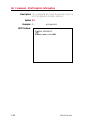
FI Command - Print Form Information
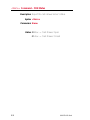
Description This command will cause the printer to print a
list of all forms stored in memory.
Syntax FI
Example: FI¿
:prints forms list
Will Produce:
3-42
980352-001 Rev.A
FK Command - Delete Form
Description This command is used to delete forms from
memory.
Syntax FK [ "FORMNAME" | "*" ]
Parameters “FORMNAME” = By entering the name of a
form, that form will be deleted from
memory.
· The name may be up to 8 characters long.
· Form names stored by the printer are case
sensitive and will be stored exactly as entered
on the FS command line; i.e. “FORM1”,
“form1” and “FoRm1” are three different
forms when stored into the printer or when retrieved by the user.
· D eletin g a sin g le fo rm req u ires t he
FK”FORMNAME” be issued twice for each
form to be deleted. Some label generation
programs re-issue forms (form delete and
store) every time a label is printed which reduces flash memory life.
“*” = By including an “*” (wild card), ALL
forms will be deleted from memory. The
FK”*” does not need to be issued twice
to delete all forms.
Example: FK"AFORM"¿
3-43
FK"AFORM"¿
:deletes form “AFORM”
:second delete form “AFORM” required
:for flash printers
FK"*"¿
:deletes all forms
980329-001 Rev.A
FR Command - Retrieve Form
Description Use this command to retrieve a form that was
previously stored in memory.
Syntax FR"FORMNAME"
Parameters “FORMNAME” = This is the form name
used when the form was stored.
· The name may be up to 8 characters long.
· Form names stored by the printer are case
sensitive and will be stored exactly as entered
on the FS command line; i.e. “FORM1”,
“form1” and “FoRm1” are three different
forms when stored into the printer or when retrieved by the user.
Example: FR"TEST1"¿
:retrieves the form named TEST1
To print a list of the forms currently stored in
memory, use the FI command.
3-44
980352-001 Rev.A
FS Command - Store Form
Description This command begins a form store sequence.
Syntax FS"FORMNAME"
Parameters “FORMNAME” =This is the form name that
will be used when retrieving the stored
form.
· The name may be up to 8 characters long.
· Form names stored by the printer are case
sensitive and will be stored exactly as entered
on the FS command line; i.e. “FORM1”,
“form1” and “FoRm1” are three different
forms when stored into the printer or when retrieved by the user.
· Global commands such as EI, EK, ES, FI,
FK, GI, GK, GM, I, M, N, P, TS, U, UE,
UF, UG, Y, W, ?, ^@ should not be used in
a form store sequence.
Form name, AUTOFR, is reserved for automatic,
single form recall, see page 3-9 for details.
❏All commands following FS will be stored in
forms memory until the FE command is received, ending the form store process.
❏Delete a form prior to updating the form by
using the FK command. If a form (with the
same name) is already stored in memory, issuing the FS command will result in an error
and the previously stored form is retained.
❏To print a list of the forms currently stored in
memory, use the FI command.
❏A form will not store if sufficient memory is
not allocated to form memory. See the M
command for details on adjusting and configuring memory to store forms (graphics and
soft fonts).
980352-001 Rev.A
3-45
FS Command - Store Form
Example: ¿
FK"TESTFORM"¿
FS"TESTFORM"¿
:delete form “TESTFORM”
:begins the form store sequence of
:the form “TESTFORM”
V00,15,N,"Enter Product Name:"¿
B10,20,0,3,2,10,100,B,"998152.001"¿
A50,200,0,3,1,1,N,"Example Form"¿
A50,400,0,3,1,1,N,"Model Name: “V00¿
FE¿
FI¿
3-46
:ends form store sequence
:prints list of stored forms
980352-001 Rev.A
GG Command - Print Graphics
Description Use this command to print a PCX (format)
graphic that has been previously stored in
printer memory.
Syntax GGp1,p2,{"NAME" | Variable Data}
Parameters p1 = Horizontal start position (X) in dots.
p2 = Vertical start position (Y) in dots.
“NAME” or Variable Data = This is the
graphic name used when the graphic
was stored. This name can be supplied
via variable data (V00 - V99).
· The name may be up to 8 characters long.
· Graphic names stored by the printer are case
sensitive and will be stored exactly as entered
w ith th e GM co mma n d lin e; i. e .
“GR APHIC1”, “g ra p hic1” a nd
“graPHic1” are three different graphics
when stored into the printer or when retrieved
by the user.
Example: GG50,50,"LOGO1"↵
FK"TESTFORM"¿
FS"TESTFORM"¿
:delete form “TESTFORM”
:begins the form store sequence of
:the form “TESTFORM”
V00,8,N,"Enter Graphic Name:"¿
GG50,50,V00¿
FE¿
:ends form store sequence
980352-001 Rev.A
FR"TESTFORM"
?¿
LOGO1
:retrieves the form named TESTFORM
:Download variables
:Graphic name to be recalled and
:printed
P1¿
:Print one label with graphic LOGO1
3-47
GI Command - Print Graphics Information
Description This command will cause the printer to print a
list of all graphics stored in memory.
Syntax GI
Example: GI¿
:prints graphics list
Will Produce:
3-48
980352-001 Rev.A
GK Command - Delete Graphics
Description Use this command to delete graphics from
memory.
Syntax GK {“NAME”|"*"}
Parameters “NAME” = By entering the name of a
graphic, that graphic will be deleted
from memory.
· Graphic names stored by the printer are case
sensitive and will be stored exactly as entered
with the GM command line; i.e. “LOGO1”,
“logo1” and “LoGo1” are three different
graphics when stored into the printer or when
retrieved by the user.
· Deleting a single graphic requires that the
GK”FORMNAME” command string be issued twice for each form deleted. Some label
generation programs re-issue graphics
(graphic delete and store) every time a label is
printed which will reduce flash memory life.
“*” = By including an “*” (wild card), ALL
graphics will be deleted from memory.
The GK”*” does not need to be issued
twice to delete all graphics.
Example: GK"LOGO"↵
980352-001 Rev.A
GK"LOGO"↵
:deletes graphic “LOGO”
:second delete graphic “LOGO” required
:for flash printers.
GK"*"↵
:deletes all graphics
3-49
GM Command - Store Graphics
Description Use this command to store PCX graphics files in
memory.
Syntax GM"NAME"p1¿
“DATA”
Parameters “NAME” = This is the graphic name that will
be used when retrieving the stored
graphic.
· The name may be up to 8 characters long.
· Graphic names stored by the printer are case
sensitive and will be stored exactly as entered
with the GM command line; i.e. “LOGO1”,
“logo1” and “LoGo1” are three different
graphics when stored into the printer or when
retrieved by the user.
p1 = This is the file size in bytes. Use the DOS
DIR command to determine the exact file
size.
“DATA” = Graphic data in 1-bit (black &
white) PCX (binary data) format file.
❏A graphic will not store if sufficient memory is
not allocated to graphic memory. See the M
command for details on adjusting and configuring memory to store graphics (forms and
soft fonts).
❏Verify the proper storage of the graphic with
the GI command.
3-50
980352-001 Rev.A
GM Command - Store Graphics
Example: GK"LOGO1"↵
GK"LOGO1"↵
GM"LOGO1"584↵
DATA
:deletes graphic “LOGO1” - Required
:second delete graphic - Required
:Prepares printer to receive graphic
:“LOGO1”
: Data string in PCX format
If using a DOS system, the PCX format file (binary data) portion can be sent to the printer using the DOS COPY command. For example, if
you have a PCX file named LOGO1.PCX in
your current directory, the appropriate command would be:
COPY LOGO1.PCX PRN /b
After downloading, the GI command can be
used to verify that the graphic was successfully
stored.
Example: First, create a text file “STOREIT.TXT” with an
ASCII text editor, as follows:
¿
GK“WORLD”¿
GK“WORLD”¿
GM"WORLD"2004¿
Where WORLD is the name of the graphic and
2004 is the size (in bytes) of the PCX file.
Next, at the DOS prompt, type:
COPY STOREIT.TXT + WORLD.PCX PRN /b
980352-001 Rev.A
3-51
GW Command - Direct Graphic Write
Description Use this command to load binary graphic data
directly into the Image Buffer memory for immediate printing. The printer does not store
graphic data sent directly to the image buffer.
The graphic data is lost when the image has finished printing, power is removed or the printer
is reset. Commands that size (Q and q) or clear
(N and M) the image buffer will also remove
graphic image data.
Syntax GWp1,p2,p3,p4DATA¿
Parameters p1 = Horizontal start position (X) in dots.
p2 = Vertical start position (Y) in dots.
p3 = Width of graphic in bytes. Eight (8) dots
= One (1) byte of data
p4 = Length of graphic in dots (or print lines).
DATA = Raw binary data without graphic file
formatting. Data must be in bytes. Multiply the width in bytes (p3) by the number of print lines (p4) for the total
amount of graphic data. The printer automatically calculates the exact size of
the data block based upon this formula.
3-52
980352-001 Rev.A
I Command - Character Set Selection
Description Use this command to select the appropriate
character set for printing and display (KDU).
Syntax Ip1,p2,p3
Parameters p1 = Number of data bits - 8 for 8 bit data or
7 for 7 bit data.
p2 = Printer Code page/Language Support
8 Bit Data
980352-001 Rev.A
7 Bit Data
p2
Code
Page
Description
0
DOS 437
English - US
0
USA
1
DOS 850
Latin 1
1
British
2
DOS 852
Latin 2
(Cyrillic II/Slavic)
2
German
3
DOS 860
Portuguese
3
French
4
DOS 863 French Canadian
4
Danish
5
DOS 865
Nordic
5
Italian
6
DOS 857
Turkish
6
Spanish
7
DOS 861
Icelandic
7
Swedish
8
DOS 862
Hebrew
8
Swiss
9
DOS 855
Cyrillic
10 DOS 866
Cyrillic CIS 1
11 DOS 737
Greek
12 DOS 851
Greek 1
13 DOS 869
Greek 2
A
Windows
1252
Latin 1
B
Windows
1250
Latin 2
C
Windows
1251
Cyrillic
D
Windows
1253
Greek
E
Windows
1254
Turkish
F
Windows
1255
Hebrew
p2 Description
3-53
I Command - Character Set Selection
p3 = KDU Country Code (8 bit data only)
KDU Country Code (8 bit only)
032 Belgium
049 Germany
027 S. Africa
002 Canada
031 Netherl’ds 034 Spain
045 Denmark
039 Italy
358 Finland
003 Latin Am. 041 Swizerl’d
033 France
047 Norway
044 U.K.
351 Portugal
001 U.S.A.
046 Sweden
The default setting is I8,0,001. See Appendix
A for EPL2 standard font character maps.
3-54
980352-001 Rev.A
JB Command - Disable Top Of Form Backup
Description This command disables the Top Of Form
Backup feature when printing multiple labels.
At power up, Top Of Form Backup will be enabled.
Syntax JB
Example: JB¿
With the JB command enabled, the first label will
backup to the Top Of Form before printing. This preserves the first label which has stopped approximately one-half inch from the print head. This is the
label's tear away point as set by the previous print
operation.
980352-001 Rev.A
3-55
JF Command - Enable Top Of Form Backup
Description This command enables the Top Of Form
Backup feature and presents the last label of a
batch print operation. Upon request initiating
the printing of the next form (or batch), the last
label backs up the Top Of Form before printing
the next label.
Syntax JF
Example: JF¿
3-56
980352-001 Rev.A
LE Command - Line Draw Exclusive
Description Use this command to draw lines with an “Exclusive OR” function. Any area, line, image or field
that this line intersects or overlays will be “reversed out” or inverted. In other words, all black
will be reversed to white and all white will be reversed to black within the line’s area (width and
length).
Syntax LEp1, p2, p3, p4
Parameters p1 = Horizontal start position (X) in dots.
p2
= Vertical start position (Y) in dots.
p3
= Horizontal length in dots.
p4
= Vertical length in dots.
Example: N↵
LE50,200,400,20↵
LE200,50,20,400↵
P1↵
:clear image buffer
:draw a line
:draw another line
:print one label
Will Produce:
980352-001 Rev.A
3-57
LO Command - Line Draw Black
Description Use this command to draw black lines, overwriting previous information.
Syntax LOp1,p2,p3,p4
Parameters p1 = Horizontal start position (X) in dots.
p2 = Vertical start position (Y) in dots.
p3 = Horizontal length in dots.
p4 = Vertical length in dots.
Example: N↵
LO50,200,400,20↵
LO200,50,20,400↵
P1↵
:clear image buffer
:draw a line
:draw another line
:print one label
Will Produce:
3-58
980352-001 Rev.A
LS Command - Line Draw Diagonal
Description Use this command to draw diagonal black lines,
overwriting previous information.
Syntax LSp1,p2,p3,p4,p5
Parameters p1 = Horizontal start position (X) in dots.
p2 = Vertical start position (Y) in dots.
p3 = Line thickness in dots.
p4 = Horizontal end position (X) in dots.
p5 = Vertical end position (Y) in dots.
Example: N↵
:clear image buffer
LS10,10,20,200,200↵ :draw a diagonal line
P1↵
:print one label
Will Produce:
980352-001 Rev.A
3-59
LW Command - Line Draw White
Description Use this command to draw white lines, effectively erasing previous information.
Syntax LWp1,p2,p3,p4
Parameters p1 = Horizontal start position (X) in dots.
p2 = Vertical start position (Y) in dots.
p3 = Horizontal length in dots.
p4 = Vertical length in dots.
Example: N↵
LO50,100,400,20↵
LO50,200,400,20↵
LO50,300,400,20↵
LW200,50,20,400↵
P1↵
:clear image buffer
:draw black line
:draw another black line
:draw another black line
:draw a white line over all 3 black lines
:print 1 label
Will Produce:
3-60
980352-001 Rev.A
M Command - Memory Allocation
Description This command no longer changes memory allocation. It was originally used for SRAM and
early model flash printers. The command now
allows the programmer to set the size of forms
memory only. The reminder of the storage
memory will be shared by soft fonts and graphics data.
Syntax Mp1,p2,p3
Parameters p1 = Parameter ignored, but required to process. Represents Image buffer size in
whole KBytes.
p2 = Form(s) memory size in whole KBytes.
The parameter, p2 (form memory size),
inversely effects the size of the shared
graphics/soft fonts memory.
p3 = Parameter ignored, but required to process. Graphics (and soft font) memory
size in whole Kbytes.
If the M command is issued, then all three parameters must be present.
Available memory and the current allocation of
memory can be displayed with the U command or
an AutoSense procedure, see the printer user’s manual for details.
980352-001 Rev.A
3-61
N Command - Clear Image Buffer
Description This command clears the image buffer prior to
building a new label image.
Syntax N
Do not use the N command within stored forms.
Example: ¿
N¿
:activates command processing
:clears the image buffer
Always send a Line Feed (LF) prior to the N command to ensure that the printer is initialized.
3-62
980352-001 Rev.A
o Command - Cancel Software Options
Description This command allows the user to cancel most
printer customization parameters set by o series
commands.
Parameters set by the following commands are
canceled and returned to default operation:
· oH
· oM
· oE
Syntax o
Parameters None
The o command is a global printer command.
❏It can not be issued inside of a form.
❏It must be issued prior to issuing a text or bar
code command (and printing).
980352-001 Rev.A
3-63
oB Command - Cancel Auto Bar Code Optimization
Description: This command allows the advanced programmer to disable bar code optimization for rotated
(90° & 270°) bar codes.
Syntax: oB
Parameters: None
The oB command is a global printer command.
❏It can not be issued inside of a form.
❏It must be issued prior to issuing a bar code
command (and printing).
To reapply bar code defaults, issue a o (small
letter “o”) command. See page C-63 for important details on the effects of using the o command.
Reset the printer with a ^@ command with
flash firmware printers or cycle printer power to
clear the oB command and return the printer to
normal operation.
Zebra Technologies Corporation does not warrant,
support, or endorse the use of bar codes generated
by the printer after a oB command has been issued.
Zebra Technologies Corporation does not support
this feature other than with the information supplied
in this document.
3-64
980352-001 Rev.A
oE Command - Line Mode Font Substitution
Description: This command is a Page Mode (EPL2) command that allows the printer to set alternate
Line Mode font character sets. The fonts are
activated by the oE command and are intended
for EPL1 emulation.
Syntax: oEp1,p2,p3,p4,p5
p1 = 5 x 7 bitmap font - Normal (CCSET4)
Line Mode EPL1 Compatibility Font A0
Total character area is 8 x 11 dots
p2 = 5 x 7 bitmap font - Bold (CCSET4)
Line Mode EPL1 Compatibility Font A0
Total character area is 8 x 11 dots
p3 = 5 x 7 bitmap font - Doubled (CCSET4)
Line Mode EPL1 Compatibility Font A0
Total character size is 8 x 11 dots
p4 = 14 x 22 bitmap font - (CCSET1)
Line Mode EPL1 Compatability Font A
Total character area is 16 x 26 dots
p5 = 10 x 18 bitmap font - (CCSET3)
Line Mode EPL1 Compatability Font A
Total character area is 12 x 22 dots
❏Parameters p1-p5 are preloaded soft fonts.
❏Parameters p1-p5 must be all belower case
alpha soft fonts. See the ES command on
page 3-35 for more details on soft fonts.
❏The EPL2 font sets 2 & 4 can be restored as
the default Line Mode fonts by sending the o
command without a parameter.
980352-001 Rev.A
3-65
oH Command - Macro PDF Offset
Description Use this command to place addition secondary,
associated Macro PDF symbols for the continuation of data greater than a single PDF 417 bar
code can store.
This command must precede any PDF 417 bar code
commands in order to print Macro PDF (multiple bar
code) symbols from a single b command's data field.
Syntax oHp1, p2
Parameters p1 = Horizontal offset position (X) in dots of
the next Macro PDF bar code symbol.
p2 = Vertical offset position (Y) in dots of the
next Macro PDF bar code symbol.
See the following page for an example.
3-66
980352-001 Rev.A
oH Command - Macro PDF Offset
Example: N¿
q784¿
Q1215,24¿
R0,0¿
oH0,500¿
¿
N¿
b80,100,P,700,600,x2,y7,l100,r100,f0,s5,"\
Fourscore and seven years ago our fathers...
<<< the rest of Lincoln’s Gettysburg Address HERE >>>
... and that government of the people, by the people, for the people
shall not perish from the earth.
"¿
P¿
Will Produce:
980352-001 Rev.A
3-67
oM Command - Disable Initial Esc Sequence Feed
Description This command disables the automatic label calibration routine executed by the printer upon
receiving the first escape command sequence
from the Windows printer driver. The printer
normally measures a single label and sets the
top of form prior to printing the first label after a
power-up reset. The Windows™ printer driver
issues escape sequences when printing.
This command’s primary use is to save
preprinted forms such as serialized labels, tags
or tickets.
Syntax oM
This command must be issued prior to printing
with the Windows driver’s or any other Escape
(esc) mode printing operation.
To reinitialize label calibration, issue a o (111
dec. or 6F hex.) command.
3-68
980352-001 Rev.A
oR Command - Character Substitution (Euro)
Description This command allows the advanced programmer to substitute the Euro currency character
for any ASCII character in printer resident font
numbers 1-4.
The original character can be restored by sending the oR command without a parameter.
Syntax oR [p1,p2]
Parameters: p1 = E
If the p2 parameter is not provided,
then the Euro character will map to
code page position 213 decimal (D5
hexadecimal) for all code pages.
p2 = Decimal number
Range: 0 to 255
The active code page’s ASCII character
map position to be replaced by the Euro
character. The Euro character will be active in this map position for all code
pages.
See the I command for details on code
page selection.
None = No Parameters (p1/p2) resets to all
code pages to original default character
mapping.
Optionally, to reapply normal character operations, issue a o (111 dec. or 6F hex.) command.
See page 3-63 for important details on the effects of using the o command.
The Euro character is not supported in Font 5 character set.
980352-001 Rev.A
3-69
oR Command - Character Substitution (Euro)
The oR command is a global printer command.
❏It can not be issued inside of a form.
❏It must be issued prior to issuing a text command (and printing).
❏Effects a single character on a single code
page. Changing the character position will
restore the original character.
❏Flash memory printer parameter data is preserved until it is changed by the oR command or reprogramming of the printer.
Example: oRE¿
3-70
: Places the Euro character into character
: map position 213 decimal
: (D5 hexadecimal)
oRE,128¿
: Places the Euro into character map
: position 128 decimal (80 hexadecimal)
oR¿
: Clears Character Substitution,
: Restores default character maps
980352-001 Rev.A
oW Command - Customize Bar Code Parameters
Description: This command allows the advanced programmer to modify specific bar code parameters to
exceed the specified bar code’s design tolerances, i.e. reduce the bar code size.
Using the oW command may cause bar codes to become unreadable by some or all bar code scanners.
Syntax: oWp1,p2,p3,p4,p5
Parameters: p1 = Initial width narrow white bar.
Default value is 2
p2 = Initial width narrow black bar.
Default value is 2
p3 = Initial width wide white bar.
Default value is 4
p4 = Initial width wide black bar.
Default value is 4
p5 = Initial bar code gap.
Default value is 3
The oW command is a global printer command.
❏They can not be issued inside of a form.
❏They must be issued prior to issuing a bar
code command (and printing).
❏Use only one bar code format. Using more
than one bar code may cause unpredictable
results or operation.
❏Issue all 5 command parameters (p1-5 ). Use
the default parameter values as place holders.
❏Bar code printed with this command should
be printed in the picket fence orientation (0º
& 180º rotations) to maximize scanning.
980352-001 Rev.A
3-71
oW Command - Customize Bar Code Parameters
Reset the printer with a ^@ or o commands
with flash firmware printers or cycle printer
power to clear the oW command and return the
printer to normal operation. See page C-63 for
important details on the effects of using the o
command.
The B command parameters p5 & p6 must be
set to 0 to use bar codes customized with this
command.
The oW command has been tested for parameter
functionality for Bar Code 39 only. The oW command may also function with Codabar and Interleaved 2 of 5 bar code, but they have not been
functionally verified for this command.
Zebra Technologies Corporation does not warrant,
support, or endorse the use of bar codes generated
by the printer after a oW command has been issued.
Zebra Technologies Corporation does not support
this feature other than with the information supplied
in this document.
3-72
980352-001 Rev.A
O Command - Hardware Options
Description Use this command to select various printer options. Options available vary by printer
configuration.
Syntax O[C[p1], D, P, L, S]
Parameters D = Enable Direct Thermal Mode, use this
option when using direct thermal media
in a thermal transfer printer.
P = Enable Label Dispense Mode Portables
L = Enable Label Dispense Mode - Tap
to Print. The printer will present each
label and wait for a tap of the feed
switch before printing the next label.
Use this mode when printing multiple
copies of liner-free labels.
C = Enable optional Label Liner Cutter.
The cutter will cut at the end of each
form as specified by the Q command.
Cp1 = Batch Print Labels and Liner Cut.
p1= Sets the number of labels to print
prior to cut.
If a number between 1 - 255 is specified
for p1, the printer will cut after the specified number of labels have been
printed.
If b is specified for p1, the “batch print
& cut” feature is enabled. This feature
uses the P command to control cutter
operation.
S = Reverse the Transmissive (Gap) Sensor Operation.
980352-001 Rev.A
3-73
O Command - Hardware Options
Examples: O
OC
OD
Od
3-74
:disables all options.
:enables cutter only, labels are cut after each
:label is printed, disables all other options
:enables direct thermal mode on thermal transfer
:printers, disables all other options
:disables diagnostic dump mode and disables
:all other options
OCb
...
:labels are cut after a batch of five has printed,
:disables all other options
P5
:Sets the number of labels to print before the cut
980352-001 Rev.A
OEPL1 Command - Set Line Mode
Description: This command is used to switch the printer operating mode from Page Mode (EPL2) to Line
Mode (EPL1 emulation).
Line Mode configuration setting is retained after
reset has been issued or power has been cycled.
Syntax OEPL1
Example: OEPL1¿
Returning to The Line Mode command EPL2 can be sent to
Page Mode the printer to return the printer to Page (EPL2)
Mode operation.
The EPL2 command is preceded by an ESCape
(27 dec or 1Bh) character and followed by a line
feed (LF - 10 dec or 0A hex), a carriage return
(CR - 13 dec or 0D hex) or CR/LF.
Example: ¬EPL2¿
980352-001 Rev.A
3-75
P Command - Print
Description Use this command to print the contents of the
image buffer.
Syntax Pp1, [p2]
Parameters p1 = Number of label sets.
Range = 1 to 65535
p2 = Number of copies of each label (used in
combination with counters to print multiple copies of the same label).
Range = 1 to 65535
The P command cannot be used inside of a stored
form sequence. For automatic printing of stored
forms, use the PA command.
Examples: P1↵
P2,1↵
P5,2↵
3-76
:prints one label set
:prints 2 label sets of one label each
:prints 5 label sets of 2 labels each
980352-001 Rev.A
PA Command - Print Automatic
Description Use this command in a stored form sequence to
automatically print the form (as soon as all variable data has been supplied).
Syntax PAp1, [p2]
Parameters p1 = Number of label sets. Can be variable
data.
Range: 1 to 9999
p2 = Number of copies of the same label.
Can be variable data.
Range: 1 to 9999
Sets the number of copies of each label
(used in combination with counters) to
print multiple copies of the same label.
This value is only set when using counters.
Example: FK"1"↵
: delete form named “1"
FS"1"↵
: start form store sequence
V00,10,N,"prompt:"↵ : define variable 00
V01,1,N,"prompt:"↵ : define variable 01
V02,4,N,"prompt:"↵ : define variable 02
A24,24,0,4,1,1,N,V00↵
: write a line of text including variable
PAV01,V02↵
: print 1 label automatically
FE↵
: end form store sequence
FR"1"↵
?↵
This Is Text¿
3¿
2¿
980352-001 Rev.A
: retrieve form “1"
: get variables
: data for V00
: data for V01= p1- number of sets
: data for V02= p2 - number of copies
3-77
q Command - Set Label Width
Description Use this command to set the width of the printable area of the media.
Syntax qp1
Parameters p1 = The width of the label measured in dots.
The q command will cause the image buffer to
reformat and position to match the selected label width (p1).
Image Buffer
Positioning - Center
Aligned Printers
Print Head
Max.
Image
Buffer
Printable
Area
Max.
Image
Buffer
q
Center Alignment
Image Buffer
Positioning - Left
Aligned Printers
Print Head
Printable
Area
Image
Buffer
Q
q
Left Alignment Edge
3-78
980352-001 Rev.A
q Command - Set Label Width
All Printers
(Exceptions - 2746 & 2348)
This command will automatically set the left margin
according to the following rules:
(print head width - label width) / 2
The q value affects the available print width. Minimizing the q value will maximize the print length and
print speed (double buffering).
If the R Command (Reference Point) is sent after this
command, the image buffer will be automatically reformatted to match the width of the print head and is
offset by the R command specified image buffer
starting point, nullifying the q command.
Example: q416↵
980352-001 Rev.A
:sets label width to 416 dots wide
3-79
Q Command - Set Form Length
Description Use this command to set the form and gap length
or black line thickness when using the transmissive
(gap) sensor, black line sensor, or for setting the
printer into the continuous media print mode.
The Q command will cause the printer to recalculate and reformat image buffer.
Syntax Qp1,p2[±p3]
Parameters p1 = Label length measured in dots
Default: Set by the AutoSense of media.
Maximum Value: 65535 (dots)
· Distance between edges of the label or black
line marks.
· For continuous mode, the p1 parameter sets
the feed distance between the end of one
form and beginning of the next.
p2 = Gap length or thickness of black line
Range: 16-240 (dots) for 203 dpi printers
[18-240 (dots) for 300dpi printers]
Gap Mode - By default, the printer is in
Gap mode and parameters are set with
the media AutoSense.
Black Line Mode - Set p2 to B plus
black line thickness in dots. See the
Gap mode range.
Continuous Media Mode
Set p2 to 0 (zero)
The transmissive (gap) sensor will be
used to detect the end of media.
±p3 =Offset length measured in dots
· Required for black line mode operation.
· Optional for Gap detect or continuous media
modes. Use only positive offset values.
3-80
980352-001 Rev.A
Q Command - Set Form Length
AutoSense routine does not detect black line
or continuous media.
All EPL2 printers have a transmissive (gap) sensor designed to detect the top of each label or
tag. It does this in one of two ways:
· Sensing through the label liner at the gap between labels.
· Looking through a hole (notch) in the tag.
Printers equipped with a black line sensor can
determine the top of each label or tag by sensing
a “black line” preprinted on the media backing.
Sensor location is important when selecting the
proper of label or tag type for printing. See the
printer user’s manual for specific information on
alignment, adjustment, and position of the
transmissive (gap) or reflective (black line) sensors.
If the label size is not set properly, the printer may
print off the edge of the label or tag and onto the
backing or platen roller. Repeated printing off the
edge of the label can cause excessive print head
wear.
Maintain a minimum margin of 0.04 inches (1 mm)
on all sides of the label.
Setting the label size to large can cause the printer to
skip labels.
980352-001 Rev.A
3-81
Q Command - Set Form Length
Examples:
Standard Label
p1
p2
Where:
p1 = 20.0 mm (160 dots)
p2 = 3.0mm (24 dots)
The Q command would be:
Q160,24↵
Butterfly Label
p1
p2
p3
Where:
p1 = 12.5 mm (100 dots)
p2 = 3.0mm (24 dots)
p3 = 3.0mm (24 dots)
The Q command would be:
Q100,24+24↵
3-82
980352-001 Rev.A
Q Command - Set Form Length
Black Line On Perforation
p1
p2
Perforation
p3
Where:
p1 = 31.0 mm (248 dots)
p2 = 7.0mm (56 dots)
p3 = 0.5 mm (4 dots)
The Q command would be:
Q248,B56+4↵
Black Line Between Perforation
p1
Perforation
p2
p3
Where:
p1 = 31.0 mm (248 dots)
p2 = 7.0mm (56 dots)
p3 = 17 mm (136 dots)
The Q command would be:
Q248,B56-136↵
980352-001 Rev.A
3-83
r Command - Set Double Buffer Mode
Description: Use this command to disable or reenable the
double buffer image (label) printing. The double buffer feature is a automatically tested and
set by the q and Q commands.
Syntax: rp1
Parameters: p1 = N - Disable Double Buffer Mode
Y - Re-enable the Double Buffer Mode if
the printer memory supports the image
buffer size set by Q and q parameters
The rN command must follow the q and Q commands in a form (label) program.
Verify the image buffer status with the U command(s). See page 2-2, for a sample of the Dump
Mode Printout.
3-84
980352-001 Rev.A
R Command - Set Reference Point
Description Use this command to move the reference point
for the X and Y axes. All horizontal and vertical
measurements in other commands use the setting for R as the origin for measurements. Use
the R command as an alternative to sending the
q command to position (center) labels that are
narrower than the print head.
Syntax Rp1,p2
Parameters p1 = Horizontal (left) margin measured in
dots.
p2 = Vertical (top) margin measured in dots.
The R command interacts with image buffer setting, as follows:
· The R command forces the printer to use the
full width of the print head as the width of the
image buffer. The R command overrides the
q commands print width setting.
· Rotate the image buffer with the Z command
to establish top and left margins (ZT) or the
bottom and right margins (ZB).
· When positioned correctly, prevents printing
off two (2) edges of the label opposite the 0,0
reference point.
Use the Q and R commands together for the easiest
method of positioning form elements in the print image in left aligned printers: 2746, TLP2046 and
2344 (Eclipse).
Repeated printing off the edge of the label can cause
excessive print head wear.
980352-001 Rev.A
3-85
S Command - Speed Select
Description Use this command to select the print speed.
Syntax Sp1
Parameters p1 = Speed select value.
Model
2722
2742
3742
2824
2844
2443 (Orion)
2746
2348
2684 (Strata)
Example: S2¿
3-86
Value
0
1
2
1
2
3
4
1
2
3
2
3
4
5
6
1
2
3
4
Speed
1.0 ips (25 mm/s)
1.5 ips (37 mm/s)
2.0 ips (50 mm/s)
1.5 ips (37 mm/s)
2.0ips (50 mm/s)
2.5 ips (63 mm/s)
3.5 ips (83 mm/s)
1.5 ips (37 mm/s)
2.0ips (50 mm/s)
2.5 ips (63 mm/s)
2.0 ips (50 mm/s)
3.0 ips (75 mm/s)
4.0 ips (100 mm/s)
5.0 ips (125 mm/s)
6.0 ips (150 mm/s)
1.0 ips (25 mm/s)
2.0 ips (50 mm/s)
3.0 ips (75 mm/s)
4.0 ips (100 mm/s)
:selects 2 ips (50 mmps)
980352-001 Rev.A
TD Command - Define Date Layout
Description Use this command to define the date format
when printing.
Use the variable TD in a Text or Bar Code (A & B
commands) DATA parameter to print the date.
Syntax TDp1[|p2|p3]
Parameters p1, p2, p3 = The parameters describe the
format of the date display. At lease one
parameter must be supplied. Each parameter can be any of the acceptable
values listed below.
Value
Description
y2
Year displayed as 2 digits (95)
y4
Year displayed as 4 digits (1995)
me
Month displayed as 3 letters (JAN)
mn
Month displayed as 2 digits (01)
dd
Day displayed as 2 digits (15)
| = Separator character. The separator may
be any ASCII character value between
032 and 063. The separator character is
printed between the results of each of
the supplied parameters.
This command only works in printers equipped with
the Real Time Clock time and date option.
Examples: If the current date is January 15, 2000:
TDy2/me/dd↵
TDdd-me-y4↵
TDdd,mn,y4↵
:00/JAN/15
:15-JAN-2000
:15,01,2000
TDdd/me/y2
A100,100,0,4,1,2,N,"Today is"TD
A100,200,0,4,1,2,N,"Next Week-"TD+07
A100,300,0,4,1,2,N,"Next Month-"TD+30
A100,400,0,4,1,2,N,"Two Months-"TD+61
980352-001 Rev.A
:15/09/00
:Today is 15/09/00
:Next Week-22/09/00
:Next Month-15/10/00
:Two Months-15/11/00
3-87
TS Command - Set Real Time Clock
Description Use this command to set the time and date in
printers equipped with the Real Time Clock option.
Syntax TSp1,p2,p3,p4,p5,p6
Parameters p1 = Month
Range: 01 to 12
p2 = Day
Range: 01 to 31
p3 = Year
Last two digits of Year (e.g. 95)
Range: Years 1991- 1999 = 90-99
Years 2000- 2090 = 00-89
p4 = Hour in 24 hour format
Range: 00 to 23
p5 = Minutes
Range: 00 to 59
p6 = Seconds
Range: 00 to 59
Example: TS01,01,95,01,00,00 : sets the date to Jan. 1, 1995
: and the time to 1:00 a.m.
TS12,31,01,15,31,00 : sets the date to Dec. 31, 2001
: and the time to 3:31 p.m.
3-88
980352-001 Rev.A
TT Command - Define Time Layout
Description Use this command to define the time format
when printing.
Syntax TTp1[|p2|p3][+]
Parameters P1, P2, P3 = h, m, or s
These parameters describe the format of
the time display.
· At lease one parameter must be supplied.
· Each parameter can be any of the values h,
m, or s and are described below.
Value
Description
h
Hours displayed as 2 digits (e.g. 01)
m
Minutes displayed as 2 digits (e.g. 15)
s
Seconds displayed as 2 digits (e.g. 00)
[+] =
Enable 12 Hour clock format
Appending a + to the end of the command string selects 12 hour clock mode.
The times will display with an “AM” or
“PM” indicator. Default (no +) = 24
hour clock mode
| = Separator character
The separator may be any ASCII character value between 032 and 063. The
separator character is printed between
the results of each of the supplied parameters.
This command works only in printers equipped with
the Real Time Clock time and date option.
Examples: If the current time is 1:25 p.m.:
TTh:m:s+↵
TTh,m↵
TTh+↵
980352-001 Rev.A
: 01:25:00
: 13,25
: 01 PM
3-89
U Command - Print Configuration (General)
Description Use this command to print the current printer
configuration for page mode printing. The
printout is the same the Dump Mode printout
initiated by the printer's AutoSense routine. The
printer does not enter Dump Mode.
See page 2-2 for a description of this printout.
Syntax U
Example: U¿
Will Produce:
3-90
980352-001 Rev.A
UA Command - Enable Clear Label Counter Mode
Description This command sets the printer to clear (empty)
the print buffer if a media out condition is detected.
Syntax UA
A power cycle, reset, or UB command will clear
this setting.
Normal (default) operation for the printer is to
resume printing if the empty roll is replaced with
new roll (or ribbon) and finish print any labels in
the process of printing prior to a media out condition, including batch print jobs.
Example: UA¿
980352-001 Rev.A
3-91
UB Command - Reset Label Counter Mode
Description Use this command to clear the UA command
and restore the default setting to allow the
printer to resume printing a batch job if a paper
empty occurs. The page mode (EPL2) printer,
by default, will resume printing if the empty roll
is replaced with new roll (or ribbon) and finish a
batch print job.
Syntax UB
Example: UB¿
3-92
980352-001 Rev.A
UE Command - External Font Information Inquiry
Description This command will cause the printer to send information about external fonts currently stored
in the printer back to the host.
Syntax UE
The printer will send the number of external
fonts stored and each font’s name, height and
direction, to the host through the RS-232 port.
Example: UE¿
Will Produce: ###
A,xxx,y
...
...
...
A,xxx,y
980352-001 Rev.A
:number of external fonts
:first font
:A=fontname
:xxx=font height in dots
:y=direction (0=0°, 1=90°, 2=both)
:last font
3-93
UF Command - Form Information Inquiry
Description This command will cause the printer to send information about forms currently stored in the
printer back to the host.
Syntax UF
The printer will send the number of forms stored
and each form’s name to the host through the
RS-232 port.
Example: UF¿
Will Produce: ###
FORMNAME1
FORMNAME2
...
FORMNAMEn
3-94
:number of forms
: first form name
:second form name
:last form name
980352-001 Rev.A
UG Command - Graphics Information Inquiry
Description This command will cause the printer to send information about graphics currently stored in the
printer back to the host.
Syntax UG
The printer will send the number of graphics
stored and each graphic’s name to the host
through the RS-232 port.
Example: UG¿
Will Produce: ###
GRAPHICNAME1
GRAPHICNAME2
...
GRAPHICNAMEn
980352-001 Rev.A
:number of graphics
: first graphic name
: second graphic name
:last graphic name
3-95
UI Command - Host Prompts/Codepage Inquiry
Description This command will cause the printer to enable
prompts to be sent to the host and it will send the
currently selected codepage to the host through
the RS-232 port.
This command also disables software flow control (XON/XOFF). Hardware flow control is not
disabled (DTR/CTS). To restart software flow
control a reset (^@ command) or power must
be recycled.
Syntax UIp1,p2,p3
The printer will send information about the currently selected code page back to the host in the
following format:
p1 = Number of data bits.
p2 = Code page.
p3 = Country code.
The KDU automatically sends this command each
time power is applied.
Example: UI¿
See Also: I and U commands.
3-96
980352-001 Rev.A
UM Command - Codepage & Memory Inquiry
Description This command will cause the printer to send to
the host of the currently selected codepage
and memory status through the RS-232 port.
This command also disables software flow control (XON/XOFF). Hardware flow control is not
disabled (DTR/CTS). To restart software flow
control a reset (^@ command) or power must
be recycled.
Syntax UM
The printer will send information about the currently selected code page and memory status
back to the host in the following format:.
UMp1,p2,p3,p4,p5,p6,p7,p8
p1 = Image buffer size in KBytes.
p2 = Form memory allocation size in KBytes.
p3 = From memory free in KBytes.
p4 = Graphic memory allocation size in
KBytes.
p5 = Graphic memory free in KBytes.
p6 = External font memory allocation size in
KBytes.
p7 = External font memory free in KBytes.
p8 = Appends a response in the UI command data format. See UI command on
page 3-96.
Example: UM¿
See Also: I, M, U, UI and UP commands.
980352-001 Rev.A
3-97
UN Command - Disable Error Reporting
Description Cancels US command
Syntax UN
3-98
980352-001 Rev.A
UP Command - Codepage & Memory Inquiry/Print
Description This command will cause the printer to print
and send the currently selected codepage and
memory status to the host through the
RS-232 port.
This command also disables software flow control (XON/XOFF). Hardware flow control is not
disabled (DTR/CTS). To restart software flow
control a reset (^@ command) or power must
be recycled.
Syntax UP
The printer will send information about the currently selected code page and memory status
back to the host followed by printing the current
printer configuration. For an example of the
configuration printout, see the U command.
The format of data sent to the host is as follows:
UPp1,p2,p3,p4,p5,p6,p7,p8,p9
p1 = Image buffer size in KBytes.
p2 = Form memory allocation size in KBytes.
p3 = From memory free in KBytes.
p4 = Graphic memory allocation size in
KBytes.
p5 = Graphic memory free in KBytes.
p6 = External font memory allocation size in
KBytes.
p7 = External font memory free in KBytes.
p8 = Appends a response in the UI command data format. See UI command on
page 3-96.
Example: UP¿
See Also I, M, U, UI and UM commands.
980352-001 Rev.A
3-99
UQ Command - Configuration Inquiry
Description Use this command to send the printer configuration information back to the host via the serial
port.
Syntax UQ
The printer will send the printer configuration,
line by line, in ASCII to the host through the
RS-232 port. The information matches the configuration information printed in final phase of
the printer’s AutoSense routine, the Dump
Mode Printout or the U command printout.
The information and number of lines of data
sent by the printer will vary from printer to
printer depending upon the type of printer and
options installed.
Example: UQ¿
3-100
980352-001 Rev.A
US Command - Enable Error Reporting
Description Use this command to enable the printer’s status
reporting feature.
· Serial Port - If an error occurs, the printer
will send a NACK(0x15), followed by the error number, to the computer. If no errors occur, the printer will echo ACK(0x6) after each
P command.
If paper or ribbon empty occurs, the printer
will send, through the serial port, a”-07” and
“Pnnn” where nnn is the number of labels remaining to print.
· Parallel Port - If an error occurs, the printer
will print the error number and the printer’s
indicator(s) LED will indicate an error condition. See the individual printer user’s manual
for details.
Syntax US[p1]
The printer’s default setting is off.
Parameters p1 = 1 Optional Parameter
If no errors occur, the printer will echo
ACK(0x6) after each label that is successfully
printed.
980352-001 Rev.A
3-101
US Command - Enable Error Reporting
Code
3-102
Error/Status Description
00
No Error
01
Syntax Error
02
Object Exceeded Label Border
03
Bar Code Data Length Error
(e.g.: EAN-13 is a 12 or 13 digit only)
04
Insufficient Memory to Store Data
05
Memory Configuration Error
06
RS-232 Interface Error
07
Paper or Ribbon Empty
08
Duplicate Name: Form, Graphic or Soft Font
09
Name Not Found: Form, Graphic or Soft Font
10
Not in Data Entry Mode
11
Print Head Up (Open)
12
Pause Mode or Paused in Peel mode
50
Does not fit in area specified
51
Data length to long
93
PDF-417 coded data to large to fit in bar code
980352-001 Rev.A
V Command - Define Variable
Description Use this command to define variable data for
the text and bar code data fields in stored forms.
Variable data can be combined with fixed data
or other data types (counter, date, etc..) in text
or bar code data fields.
Syntax Vp1,p2,p3,"[-]PROMPT"
Parameters p1 = Variable number.
Range: 00 to 99 .
Variable (reference) numbers are sequential and must be input into a form
in ascending order.
p2 = Maximum number of characters
Range: 1 to 99 .
This is the maximum number of characters allowed in the variable field.
p3 = Field Justification.
L = Left
R = Right
C = Center
N = No Justification
Note: Right and center justification does
not apply to soft fonts.
“PROMPT” = An ASCII text field that will be
transmitted to the host (via the serial interface) each time this command is executed. Use the prompt to ask for a value
to be entered for the variable.
KDU Options [-] = Having the first character of the prompt
a single minus sign will cause the
prompt to display only once after form
retrieval.
KDU Character The KDU allows a maximum of 40 characters
Number Limit for entry into a variable data field and display.
KDU Range (p2 ): 1 to 40, but not to exceed a
total of 1500 bytes for all variables.
980352-001 Rev.A
3-103
V Command - Define Variable
Use this command in forms that require unique
data on each label. When initializing variables:
· They must be defined in order (e.g. V00 first,
V01 second...)
· They must be the next entries after the
FS"FORMNAME" command
· They must be located before any counter
variables.
To print the contents of the variable, the variable number is referenced in the “DATA” field
of the A (ASCII text) or B (Bar Code) commands.
The field justification parameter effects the way
the variable will be printed. When L of R are selected, the variable value will be printed left or
right justified in an area with a width defined by
p2 parameter.
The maximum amount of data stored as variable
data, including counter variables and data reference
overhead can not exceed 1500 bytes.
KDU Support: Internally stored variable data fields
are reset after cycling printer power or sending a reset command or pressing the Cancel.
Example: V00,15,N,"Enter Product Name:"¿
3-104
980352-001 Rev.A
W Command - Windows Mode
Description This command is used to disable/re-enable the
Windows command mode.
Syntax Wp1
Parameters p1 = Windows Mode Enabled.
Values = Y for enabled (default)
N for disabled
When enabled, the printer will accept Windows
mode escape sequences to print data. When
disabled, escape sequences will be ignored.
The Windows mode escape sequences are only
used by the optional Windows printer driver.
When working with a main frame or other
non-Windows host, this mode can be disabled
to prevent erratic operation.
980352-001 Rev.A
3-105
xa Command - AutoSense
Description This command is used to have the printer detect
the label and gap length and set the sensor levels. This command will not enter into the Dump
mode or print the printer configuration label.
Syntax xa¿
Example: xa¿
3-106
:The printer will feed labels and
: measure the labels to set the Q values
: (label & gap length) and the sensor
: levels.
: The printer is at Top of Form (TOF)
: and ready to print .
980352-001 Rev.A
X Command - Box Draw
Description Use this command to draw a box shape.
Syntax Xp1,p2,p3,p4,p5
Parameters
p1 = Horizontal start position (X) in dots.
p2 = Vertical start position (Y) in dots.
p3 = Line thickness in dots.
p4 = Horizontal end position (X) in dots.
p5 = Vertical end position (Y) in dots.
Example: N↵
X50,200,5,400,20↵
X200,50,10,20,400↵
P1↵
Will Produce:
980352-001 Rev.A
3-107
Y Command - Serial Port Setup
Description Use this command to establish the serial port
communication parameters.
Syntax Yp1,p2,p3,p4
Parameters p1 = Baud rate
p1
Description
38
38,400 baud (38K)
19
19,200 baud
96
9,600 baud
48
4,800 baud
24
2,400 baud
12
1,200 baud
p2 = Parity.
Values: O = Odd parity
E = Even parity
N = No parity
p3 = # Data bits.
Values: 7 = Seven data bits
8 = Eight data bits
p4 = # Stop bits.
Values: 1 = One stop bit
2 = Two stop bits.
After receiving this command, the printer will
automatically reset enabling the new rate.
To send commands and data to the printer, the host’s
serial port parameters must match the printer’s serial
port parameters. Verify the printer’s configuration settings with the AutoSense/Dump Mode Printout, see
the printer’s user’s manual for details.
The printer’s default serial port parameters are:
9600 baud, No Parity, 8 Data Bits, 1 Stop Bit
Change the printer’s serial port parameters with the
Y command after communication has been established with the host. The host parameters must then
be changed to resume communication.
Example: Y19,O,7,1¿
3-108
:sets 19,200 baud, odd parity,
:7 data bits and 1 stop bit.
980352-001 Rev.A
Z Command - Print Direction
Description Use this command to select the print orientation.
Syntax Zp1
Parameters p1 = Print orientation.
T = Printing from top of image buffer.
B = Printing from bottom of image
buffer.
Default Orientation = T
The top of the image buffer prints first and is viewed
by the operator as printing up side down.
Example: N¿
ZT¿
GG10,10,"WORLD"¿
A10,200,0,3,1,1,N,"This Graphic Was Printed With Orientation Set To
ZT"¿
P1¿
N¿
ZB¿
GG10,10,"WORLD"¿
A10,200,0,3,1,1,N,"This Graphic Was Printed With Orientation Set To
ZB"¿
P1¿
Will Produce:
980352-001 Rev.A
3-109
? Command - Download Variables
Description This command signals the printer to “fill-in”
variable or counter “prompt” data field.
The host system can send data representing
variables and/or counters to the printer after a
stored form containing variables and/or counters has been retrieved.
Syntax ?
DATA
The amount of data following the question
mark line must match exactly the order and total
number of variables and/or counters for that
specific form.
Data must be entered, as follows:
· Each DATA line represents a variable or
counter data field fill-in.
· Variables in ascending order
(e.g. V00 first, V01 second...)
· Counters in ascending order following
Variables (e.g. C0 first, C1 second...)
Example
FK"form1"¿
:delete form "form1"
FS"form1"¿
:begins the form store
V00,15,N,"Enter Part Name:"¿
V01,5,N,"Enter Quantity:"¿
A50,10,0,3,1,1,N,V00¿
A50,400,0,3,1,1,N,"Quantity: "V01¿
FE¿
:ends form store sequence
FR"form1"¿
?¿
Screws¿
235¿
P1¿
3-110
:retrieve for “form1"
:variables follow
:first variable
:second variable
:print one label
980352-001 Rev.A
^@ Command - Reset Printer
Description This command is used to reset the printer.
Syntax ^@¿
:where ^is 94 decimal
This command emulates Power Off and then
Power On; thus reinitializing the printer.
· The reset command is unavailable during the
operation of storing PCX graphics, soft fonts
or while the printer is in dump mode.
· The reset command cannot be used in a
stored form.
· The reset command can be sent to the printer
during all other printing operations.
· The printer will ignore all commands sent
while the reset command is executing, up to 2
seconds.
Example: ^@¿
980352-001 Rev.A
:The printer will reset
3-111
^ee Command - Error Report - Immediate
Description: Use this command to get printer error and status
report immediately. The ^ee command must
be sent via the RS-232 serial interface.
The printer will report 4 bytes back to host in the
following format:
XX<CR><LF>
XX = Error/Status code
<CR>
= Carriage Return (ASCII 13 dec.)
<LF>
= Line Feed (ASCII 10 dec.)
Syntax: ^ee
Parameters: None
Code
Error/Status Description
00
No Error
01
Syntax Error
02
Object Exceeded Label Border
03
Bar Code Data Length Error
(e.g.: EAN-13 is a 12 or 13 digit only)
04
Insufficient Memory to Store Data
05
Memory Configuration Error
06
RS-232 Interface Error
07
Paper or Ribbon Empty
08
Duplicate Name: Form, Graphic or Soft Font
09
Name Not Found: Form, Graphic or Soft Font
10
Not in Data Entry Mode (See ? Command)
11
Print Head Up (Open)
12
Pause Mode or Paused in Peel mode
50
Printer Busy - Processing Print Job
80*
Undefined
81*
Cutter Jammed or Not Installed
82*
AutoSense or Sensor Failure
83*
Illegal Interrupt occurred
84*
Excessive Media Feeding
* - Requires Intervention: Press Feed or Reset (^@ command)
3-112
980352-001 Rev.A
Appendix A - Character References
This section has character references.
Resident Fonts 1-5 Page Mode supports 5 different font sizes, numbered 1-5. Each font can be expanded both
horizontally and vertically. All fonts are
non-proportional, mono-spaced. The ASCII
value of each character is dependent on the I
command character set (code page) selection.
980352-001 Rev.A
A-1
Default Character Map
Code Page - 437
See the I command to for more information on
selecting available code pages, page 3-53.
A-2
980352-001 Rev.A
Dump Mode The printer's Dump Mode is used to troubleCharacter Map shoot programming. The printer will print all
data as sent in Dump Mode Characters, shown
below.
0
1
2
3
4
5
6
7
8
9
A
B
C
D
E
F
0 1 2 3 4 5 6 7 8 9 A BC D E F
00
0
16
J
1
17
2
18
o
© !!
3
¨
4
§
5
ª
6
§
22
38
o
h
i
25
g
26
(
40
)
41
*
42
+
28
44
n
29
30
C
15
'
39
43
e
14
&
27
E
13
%
37
G f
12
$
21
24
11
#
36
¶
8
10
"
34
20
23
9
!
33
35
7
32
19
¬
Hexidecimal - Least Significant Digit
Hexidecimal - Most Significant Digit
31
980352-001 Rev.A
,
-
45
.
46
/
47
0
48
1
49
2
50
3
51
4
52
5
53
6
54
7
55
8
56
9
57
:
58
;
59
<
60
=
61
>
62
?
63
@
64
A
65
B
66
C
67
D
68
E
69
F
70
G
71
H
72
I
73
J
74
K
75
L
76
M
77
N
78
O
79
P
80
Q
81
R
82
S
83
T
84
U
85
V
86
W
87
X
88
Y
89
Z
90
[
91
\
92
]
93
^
94
_
95
`
96
a
97
b
98
c
99
d
100
e
101
f
102
g
103
h
104
i
105
j
106
k
107
l
108
m
109
n
110
o
111
p
112
q
113
r
114
s
115
t
116
u
117
v
118
w
119
x
120
y
121
z
122
{
123
|
124
}
125
~
128
129
130
131
132
133
134
135
136
137
138
139
140
141
126
142
127
143
144
145
146
147
148
149
150
151
152
153
154
155
156
157
158
159
160
¡
161
¢
162
£
163
¤
164
¥
165
¦
166
§
167
¨
168
©
169
ª
170
«
171
¬
172
173
®
174
¯
175
°
176
±
177
²
178
³
179
´
180
µ
181
¶
182
·
183
¸
184
¹
185
º
186
»
187
¼
188
½
189
¾
190
¿
191
À
192
Á
193
Â
194
Ã
195
Ä
196
Å
197
Æ
198
Ç
199
È
200
É
201
Ê
202
Ë
203
Ì
204
Í
205
Î
206
Ï
207
Ð
208
Ñ
209
Ò
210
Ó
211
Ô
212
Õ
213
Ö
214
×
215
Ø
216
Ù
217
Ú
218
Û
219
Ü
220
Ý
221
Þ
222
ß
223
à
224
á
225
â
226
ã
227
ä
228
å
229
æ
230
ç
231
è
232
é
233
ê
234
ë
235
ì
236
í
237
î
ð
240
ñ
241
ò
242
ó
243
ô
244
õ
245
ö
246
÷
247
ø
248
ù
249
ú
250
û
251
ü
252
ý
253
þ
238
254
ï
256
239
255
A-3
A-4
980352-001 Rev.A
Appendix B - Cash Drawer Kicker Option
This section has hardware and programming
for the Cash Drawer Kicker.
Introduction The cash drawer kicker is a factory option only.
The printer requires a special PCBA to support
this option. At the time of publication, the 2824
printer is the only page mode printer model supporting the cash drawer kicker option. Check
our web site or your dealer for further updates.
980352-001 Rev.A
B-1
Cash Drawer Cable The figure below displays the pin assignments
Wiring for the printer's retail cash drawer interface. Refer to the cash draw manufacturer's documentation for proper drawer wiring.
RJ-11
Pin No. PRINTER
1
2
3
4
5
6
SGND
/SDRV1
/Sense
+24V*
/SDRV2
LGND
Male RJ-11
*+24 volts D.C. at no greater than 1.5 amps.
B-2
980352-001 Rev.A
<Esc>p Command - Generate Pulse CDK
Description Generate a drawer kicker pulse.
Syntax <Esc>pp1 p2 p3
Parameters p1 = Select Drawer
Drawer 1 (SDRV1) = 31 hex.
Drawer 2 (SDRV2) = 32 hex.
p2 = Pulse “on” time in multiples of two milliseconds (2 msec).
Range = 00 - FF hex.
p3 = Pulse “on” time in multiples of two milliseconds (2 msec). The value of p3 must
be greater than or equal to the value of
p2 .
ASCII Hex Value 1B 70 p1p2p3
(p1 represent value range 31 to 32 hex;
p2 represent value range 00 to FF hex;
p3 represent value range 00 to FF hex)
Example ←p2Bd↵
980352-001 Rev.A
: ←p = <Esc>p , the command
: 2 = p1 parameter value of 32 hex.
: B = p2 parameter value of 42 hex. for
:
132 msec pulse (66 x 2msec)
: d = p3 parameter value od 64 hex. for
:
200 msec. pulse (100 x 2msec)
B-3
<Esc>u Command - CDK Status
Description Report the cash drawer kicker’s status.
Syntax <Esc>u
Parameters None
Status 00 hex. = Cash Drawer Open
01 hex. = Cash Drawer Closed
B-4
980352-001 Rev.A