1
EPL2
Programmer’s
Manual
Manual No. 980009-001
©1999 Zebra Technologies Corporation
Rev. F
FOREWORD
This manual provides programming information for the Eltron brand printers, featuring Zebra’s
Eltron Programming Language (EPL2) command language, which are manufactured by Zebra
Technologies Corporation, Camarillo, California.
COPYRIGHT NOTICE
This document contains information proprietary to Zebra Technologies Corporation. This document and the information contained within is copyrighted by Zebra Technologies Corporation
and may not be duplicated in full or in part by any person without written approval from Zebra.
While every effort has been made to keep the information contained within current and accurate
as of the date of publication, no guarantee is given or implied that the document is error-free or
that it is accurate with regard to any specification. Zebra reserves the right to make changes, for the
purpose of product improvement, at any time.
TRADEMARKS
Zebra, Eltron, EPL2, Strata, Orion, Xport and Eclipse are trademarks of Zebra Technologies
Corporation. All other marks are trademarks or registered trademarks of their respective holders.
REVISION HISTORY
Rev. B – This version of the manual was for firmware version 2.23 and is available from Eltron in
electronic form.
Rev.C - This version of the manual was for firmware version 3.18 and is available from Eltron in
electronic form.
Rev.D - This version of the manual was for firmware version 3.20 and is available from Eltron in
electronic form.
Rev.E - This manual version coincides with EPL2 firmware version 3.99 and is available from
Eltron in electronic form.
Rev.F - This manual version coincides with EPL2 firmware version 4.03 and is available from
Eltron in electronic form.
See the Eltron web site at: www.eltron.com for an Adobe Acrobat file or call Zebra, Eltron Products Group, customer service.
ii
980009-001 Rev.F
Table of Contents
PROGRAMMING CONSIDERATIONS . . . . . . . . 1-1
Features . . . . . . . . . . . . . . . . . . . . . . . . 1-1
Command Functions . . . . . . . . . . . . . . . . . 1-2
Image Control Commands .
Printer Control Commands
Memory Control . . . . . .
Status Reporting . . . . . .
.
.
.
.
.
.
.
.
Command Conventions . . .
Basic Command Syntax . . .
Command Editor . . . . . .
Printer Memory Organization
Forms . . . .
Graphics . . .
Soft Fonts . .
Image Buffer .
.
.
.
.
.
.
.
.
.
.
.
.
.
.
.
.
.
.
.
.
.
.
.
.
.
.
.
.
.
.
.
.
.
.
.
.
.
.
.
.
.
.
.
.
.
.
.
.
.
.
.
.
.
.
.
.
.
.
.
.
.
.
.
.
.
.
.
.
.
.
.
.
.
.
.
.
.
.
.
.
.
.
.
.
.
.
.
.
.
.
.
.
.
.
.
.
.
.
.
.
.
.
.
.
.
.
.
.
.
.
.
.
.
.
.
.
.
.
.
.
.
.
.
.
.
.
.
.
.
.
.
.
.
.
.
.
.
.
.
.
.
.
.
.
.
.
.
.
.
.
.
.
.
.
.
.
.
.
.
.
.
.
.
.
.
.
.
.
.
.
.
.
.
.
.
.
1-2
1-3
1-4
1-7
.
.
.
.
.
.
.
.
.
.
.
.
1-8
1-9
1-10
1-11
.
.
.
.
.
.
.
.
.
.
.
.
1-11
1-11
1-12
1-12
Image Buffer Addressing . . . . . . . . . . . . . . . . 1-13
Sample Format . . . . . . . . . . . . . . . . . . . . . . 1-14
Installed Memory vs. Form Length . . . . . . . .
Double Buffering. . . . . . . . . . . . . . . . .
Text (Fonts) . . . . . . . . . . . . . . . . . . .
Bar Codes . . . . . . . . . . . . . . . . . . . .
Programming Sequences Affect Graphic Results .
Media Detection . . . . . . . . . . . . . . . . .
Determining Printer Firmware Version . . . . . .
.
.
.
.
.
.
.
.
.
.
.
.
.
.
.
.
.
.
.
.
.
1-14
1-16
1-18
1-20
1-21
1-21
1-22
COMMAND REFERENCE . . . . . . . . . . . .
EPL2 Command Set . . . . . . . . . . . . . . . .
A Command - ASCII Text . . . . . . . . . . . .
B Command - Bar Code . . . . . . . . . . . .
b Command - 2D Bar Code . . . . . . . . . . .
C Command - Counter . . . . . . . . . . . . .
D Command - Density . . . . . . . . . . . . . .
EI Command - Print Soft Font Information . . .
EK Command - Delete Soft Font. . . . . . . . .
ES Command - Store Soft Fonts . . . . . . . . .
FE Command - End Form Store . . . . . . . .
FI Command - Print Form Information . . . . .
FK Command - Delete Form . . . . . . . . . .
FR Command - Retrieve Form . . . . . . . . . .
FS Command - Store Form . . . . . . . . . . .
GG Command - Print Graphics . . . . . . . . .
.
.
.
.
.
.
.
.
.
.
.
.
.
.
.
.
.
.
.
.
.
.
.
.
.
.
.
.
.
.
.
.
2-1
2-2
2-4
2-7
2-10
2-11
2-14
2-15
2-16
2-16
2-17
2-18
2-19
2-20
2-21
2-23
980009-001 Rev.F
iii
GI Command - Print Graphics Information . . . .
GK Command - Delete Graphics . . . . . . . . .
GM Command - Store Graphics . . . . . . . . . .
I Command - Character Set Selection . . . . . . .
JB Command - Disable Top Of Form Backup . . .
JF Command - Enable Top Of Form Backup . . .
LE Command - Line Draw Exclusive. . . . . . . .
LO Command - Line Draw Black . . . . . . . . .
LS Command - Line Draw Diagonal . . . . . . . .
LW Command - Line Draw White . . . . . . . . .
M Command - Memory Allocation. . . . . . . . .
N Command - Clear Image Buffer . . . . . . . . .
O Command - Options Select . . . . . . . . . . .
oM Command - Disable Initial Esc Sequence Feed
P Command - Print . . . . . . . . . . . . . . . .
PA Command - Print Automatic . . . . . . . . . .
Q Command - Set Form Length . . . . . . . . .
q Command - Set Label Width . . . . . . . . . .
R Command - Set Reference Point. . . . . . . . .
S Command - Speed Select . . . . . . . . . . . .
U Command - Print Configuration (General) . . .
V Command - Define Variable. . . . . . . . . . .
X Command - Box Draw . . . . . . . . . . . . .
Y Command - Serial Port Setup . . . . . . . . . .
Z Command - Print Direction . . . . . . . . . . .
? Command - Download Variables . . . . . . . .
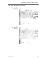
Appendix A - Standard Character Sets .
Resident Fonts . . . . . . . . . . . . . .
Fonts 1-5 . . . . . . . . . . . . . . . . .
ASCII to Hexadecimal Reference Table. .
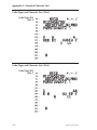
Code Page 437 Sizes 1-4
Code Page 850 Sizes 1-4
Code Page 852 Sizes 1-4
Code Page 860 Sizes 1-4
Code Page 863 Sizes 1-4
Code Page 865 Sizes 1-4
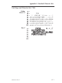
Code Page 437 Size 5 . .
Code Page 850 Size 5 . .
Code Page 852 Size 5 . .
Code Page 860 Size 5 . .
Code Page 863 Size 5 . .
Code Page 865 Size 5 . .
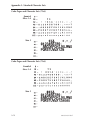
British . . . . . . . . . .
Danish . . . . . . . . . .
iv
.
.
.
.
.
.
.
.
.
.
.
.
.
.
.
.
.
.
.
.
.
.
.
.
.
.
.
.
.
.
.
.
.
.
.
.
.
.
.
.
.
.
.
.
.
.
.
.
.
.
.
.
.
.
.
.
.
.
.
.
.
.
.
.
.
.
.
.
.
.
.
.
.
.
.
.
.
.
.
.
.
.
.
.
.
.
.
.
.
.
.
.
.
.
.
.
.
.
.
.
.
.
.
.
.
.
.
.
.
.
.
.
.
.
.
.
.
.
.
.
.
.
.
.
.
.
.
.
.
.
.
.
.
.
.
.
.
.
.
.
.
.
.
.
.
.
.
.
.
.
.
.
.
.
.
.
.
.
.
.
.
.
. . .
. . . .
. . . .
. . . .
.
.
.
.
.
.
.
.
.
.
.
.
.
.
.
.
.
.
.
.
.
.
.
.
.
.
.
.
.
.
.
.
.
.
.
.
.
.
.
.
.
.
.
.
.
.
.
.
.
.
.
.
.
.
.
.
.
.
.
.
.
.
.
.
.
.
.
.
.
.
.
.
.
.
.
.
.
.
.
.
.
.
.
.
.
.
.
.
.
.
.
.
.
.
.
.
2-24
2-25
2-26
2-28
2-29
2-29
2-30
2-31
2-32
2-33
2-34
2-38
2-39
2-41
2-42
2-43
2-44
2-48
2-50
2-52
2-53
2-56
2-59
2-60
2-62
2-63
.
.
.
.
.
.
.
.
A-1
A-1
A-2
A-2
.
.
.
.
.
.
.
.
.
.
.
.
.
.
.
.
.
.
.
.
.
.
.
.
.
.
.
.
A-3
A-3
A-4
A-4
A-5
A-5
A-6
A-6
A-7
A-7
A-8
A-8
A-9
A-9
980009-001 Rev.F
French .
German
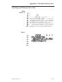
Italian .
Spanish
Swedish
Swiss. .
USA . .
.
.
.
.
.
.
.
.
.
.
.
.
.
.
.
.
.
.
.
.
.
.
.
.
.
.
.
.
.
.
.
.
.
.
.
.
.
.
.
.
.
.
.
.
.
.
.
.
.
.
.
.
.
.
.
.
.
.
.
.
.
.
.
.
.
.
.
.
.
.
.
.
.
.
.
.
.
.
.
.
.
.
.
.
.
.
.
.
.
.
.
.
.
.
.
.
.
.
.
.
.
.
.
.
.
.
.
.
.
.
.
.
.
.
.
.
.
.
.
.
.
.
.
.
.
.
.
.
.
.
.
.
.
.
.
.
.
.
.
.
.
.
.
.
.
.
.
.
.
.
.
.
.
.
.
.
.
.
.
.
.
.
.
.
.
.
.
.
.
.
.
.
.
.
.
.
.
.
.
.
.
.
A-10
A-10
A-11
A-12
A-12
A-13
A-14
Appendix B - Optional & Extended Character Sets . B-1
Fixed verses Flashed Program Firmware . . . . . . . . B-1
Fixed Firmware Optional Character Set Differences . . B-2
Flash Firmware Character Sets. . . . . . . . . . . . . . . B-2
Extended Character Set Map Reference . . . . . . . . . . B-2
Character Maps . . . . . . . . . . . . . . . . . . . . B-3
Asian Language
Character Maps . . . . . . . . . . . . . . . . . . . . . . B-3
Appendix C - Asian Character Printer Programming . C-1
Asian Character Sets Fonts 8 & 9 . . . . . . . . . . . C-1
Asian Print Memory Configuration . . . . . . . . . . . . . C-2
A Command - ASCII Text . . . . . . . . . . . . . . C-3
i Command - Asian Character Spacing . . . . . . . C-9
Appendix D - Bar Code Information . . . . . . . . . D-1
Frequently Asked Questions About
Bar Codes. . . . . . . . . . . . . . . . . . . . . . . D-1
b Command - 2D Bar Code - MaxiCode Specific Options
D-16
Using AIM Specified MaxiCode Data Formatting . . . D-19
b Command - 2D Bar Code - PDF417 Specific Options
D-20
oH Command - Macro PDF Offset . . . . . . . . . D-27
Appendix E - Real Time Clock Option Programming .
RTC Option Configurations . . . . . . . . . . . . . .
RTC Commands . . . . . . . . . . . . . . . . . . . .
Checking for Time & Date . . . . . . . . . . . . . . .
Printing the Time & Date . . . . . . . . . . . . . . .
A Command - ASCII Text with RTC . . . . . . . . .
B Command - Bar Code with RTC . . . . . . . . .
TD Command - Define Date Layout . . . . . . . .
TS Command - Set Real Time Clock . . . . . . . .
TT Command - Define Time Layout . . . . . . . .
980009-001 Rev.F
E-1
E-1
E-2
E-2
E-2
E-3
E-4
E-5
E-6
E-7
v
Appendix F - Cutter Option Programming . . . . . . F-1
Cutter Option Configurations . . . . . . . . . . . . . . . F-2
Cutter Models . . . . . . . . . . . . . . . . . . . . . . . . F-2
C Command - Cut Immediate . . . . . . . . . . . . F-3
f Command - Cut Position . . . . . . . . . . . . . F-4
OC Command - Cutter Option Select . . . . . . . . F-5
Appendix G - Advanced Programming . . . . . . . . G-1
Introduction . . . . . . . . . . . . . . . . . . . . . . . G-1
AUTOFR - Automatic Form Printing Feature . . . . G-2
Disabling AUTOFR. . . . . . . . . . . . . . . . . . . . . . G-3
Removing AUTOFR . . . . . . . . . . . . . . . . . . . . . G-3
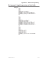
A Command – Simple Expresssions in Data Fields .
dump Command - Enable Dump Mode . . . . . .
eR Command - User Defined Error/Status Character
O Command - Options Select . . . . . . . . . . . .
o Command - Cancel Customized Settings . . . . .
oB Command - Cancel Auto Bar Code Optimization
oR Command - Character Substitution (Euro) . . .
oW Command - Customize Bar Code Parameters .
p Command - Reset Top of Form Sensing . . . . .
r Command - Buffer Mode . . . . . . . . . . . . .
U Commands - Advanced Status Commands . . . .
UA Command - Enable Clear Label Counter Mode .
UB Command - Reset Label Counter Mode . . . .
UE Command - External Font Information Inquiry .
UF Command - Form Information Inquiry . . . . .
UG Command - Graphics Information Inquiry . . .
UI Command - Host Prompts/Codepage Inquiry . .
UM Command - Codepage & Memory Inquiry . . .
UP Command - Codepage & Memory Inquiry/Print
UQ Command - Configuration Inquiry . . . . . . .
US Command - Enable Error Reporting . . . . . . .
W Command - Windows Mode . . . . . . . . . . .
xa Command - AutoSense . . . . . . . . . . . . .
^ee Command - Error Report - Immediate . . . .
^@ Command - Reset Printer . . . . . . . . . . .
Soft Fonts Overview . . . . . . . . . . . . . . . . . . .
EK Command - Delete Soft Font . . . . . . . . . .
ES Command - Store Soft Font . . . . . . . . . . .
G-4
G-6
G-7
G-8
G-9
G-10
G-11
G-13
G-15
G-16
G-17
G-18
G-19
G-20
G-21
G-22
G-23
G-24
G-26
G-27
G-29
G-30
G-31
G-32
G-33
G-34
G-35
G-36
Example of Measuring Soft Font Size . . . . . . . . . . . . G-38
Soft Fonts Programming Code Example . . . . . . . . . . . G-39
Font Bitmap Data Format . . . . . . . . . . . . . . . . . . G-40
vi
980009-001 Rev.F
Appendix H - Programming Examples . . . . . . . . H-1
Example 1 - Text and Line Graphics . . . . . . . . . . H-2
Example 2 - Text and Line Graphic Interactions . . . . H-4
Example 3 - Bar Code Variables . . . . . . . . . . . . H-6
Example 4 - Bar Code and Line Graphics Interaction . H-8
Example 5 - Sequencing Graphic Elements . . . . . . H-10
Example 6 - Steps for Downloading a PCX Graphic . . H-12
Example 7 - Printing A PCX Graphic . . . . . . . . . H-14
Example 8 - Printing Immediately: Putting It All Together H-16
Example 9 - Creating A Form . . . . . . . . . . . . . H-18
Example 10 - Steps for Downloading a Form . . . . . H-20
Example 11 - Creating a Form with Basic Variables . . H-21
Example 12 - Printing Forms with Variables . . . . . . H-23
Example 13 - Variable Justification . . . . . . . . . . H-25
Example 14 - Creating a Form with Basic Counters . . H-27
Example 15 - Numeric Counting and Printing . . . . . H-30
Example 16 - Counter Justification . . . . . . . . . . H-32
Example 17 - Printing with Forms: Putting It All Together H-34
Example 18 - Using a KDU Terminal . . . . . . . . . H-36
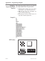
Appendix J - Interface Connection . . . . .
Serial Interface Cable Connections. . . . .
P2242 Serial Interface Cable Connections .
Parallel Interface Cable Connections . . . .
980009-001 Rev.F
.
.
.
.
. .
. . .
. . .
. . .
.
.
.
.
.
.
.
.
J-1
J-2
J-3
J-4
vii
viii
980009-001 Rev.F
PROGRAMMING CONSIDERATIONS
PROGRAMMING CONSIDERATIONS
This section contains information about the basic features, command syntax and terminology
of the Eltron Programming Language 2 (EPL2).
Features The Eltron Programming Language 2 (EPL2) is
a robust text (ASCII) based command language
used to control most Eltron brand Zebra printer
models. EPL2 takes advantage of the intelligent
features built into the printer to reduce programming overhead and minimize data transmission time.
The command set includes features for printing
labels directly or storing them, as forms, in nonvolatile memory. Counters can be incorporated
(e.g. for serialization) as well as variables that
are supplied at print time. Graphics, such as logos, can be permanently downloaded into
memory for fast recall. Soft fonts can also be
permanently downloaded to memory for later
recall.
The printer includes 2D bar codes, PDF417 and
MaxiCode (PDF417 is an option in the
TLP2046 printer). EPL2 provides extensive
controls over the height, width, and other aspects of 2D bar codes.
If the printer includes the time & date option,
EPL2 includes commands for setting as well as
980009-001 Rev.F
1-1
PROGRAMMING CONSIDERATIONS
formatting the appearance of the time and date
onto printed labels. See Appendix E for details.
Command Functions The EPL2 printer has four (4) basic command
functions:
❏ Image Control
❏ Print Control
❏ Memory Control
❏ Status Reporting
Image Control Image control commands directly affect the
Commands memory used by the printer for storing the print
image prior to printing. The image commands
assemble each of the individual elements of the
print image, (i.e. text, bar codes, lines, graphics
B&W PCX bitmaps, etc.), with small, compact
data strings. The printer creates a bitmap from
each command string element without the need
to transfer a large amount of image data
between the host and the printer.
Command
A
B
b
LE
LO
LS
LW
N
X
Description
ASCII Text
Bar Code
2D Bar Code
Line Draw Exclusive
Line Draw Black
Line Draw Diagonal
Line Draw White
Clear Image Buffer (Note 1)
Box Draw
Page
2-4
2-7
4-15
2-30
2-31
2-32
2-33
2-38
2-59
Note 1- A Line Feed (LF) issued prior to any commands will
initialize the printer for commands. The N command should be
the first command issued to erase/clear all available image
buffer space in the printer.
1-2
980009-001 Rev.F
PROGRAMMING CONSIDERATIONS
Printer Control Printer control commands set the image (label)
Commands size, position of print area, speed, density (heat
setting), control and positioning of label for cut,
peel or presentation, and printer interface and
control.
Command
D
I
JB
JF
O
P
PA
Q
q
R
S
W
Z
980009-001 Rev.F
Description
Density
Character Set
Disable Top of Form Backup
Enable Top of Form Backup
Options Select:
Thermal Transfer
Direct Thermal
Cut
Peel (Present Label)
Print
Print Automatic
Set Form/Label Length
Set Form Width
Set Reference Point
Speed Select
Windows Mode (Enable/Disable for
Windows printer driver)
Print Direction (ZB & ZT)
Page
2-14
2-28
2-29
2-29
2-39
2-42
2-43
2-44
2-48
2-50
2-52
G-30
2-62
1-3
PROGRAMMING CONSIDERATIONS
Memory Control Memory control commands provide access to
v o l a t i l e ( t e m p o r ar y ) an d n o n v o l at il e
(permanent) memory in the printer. Volatile
memory is for storing variable data and
counters. Nonvolatile memory is for storing
form, graphic data (PCX) and soft fonts.
Command
C
V
rN
?
Volatile Memory Commands
Description
Counters
Define Variable
Disable Double Buffer
Download Variables
Nonvolatile Memory Commands
Command
Description
FE
End Form Store
FK
Delete Form
Retrieve Form
FR
(and run commands within form)
FS
(Begin) Store Form
Retrieve PCX Graphic
GG
(to image buffer)
GK
Delete Graphic
GM
Store Graphics
Memory Allocation (Clear data
M
printer memory and format)
Page
2-11
2-58
H-16
2-63
Page
2-17
2-19
2-20
2-21
2-23
2-25
2-26
2-34
Memory management may be different from
printer model to model. Eltron has been adding
features and creating new products that have
required minor functional differences in memory management.
Some EPL2 printers include a removable
memory cartridge. Some printers have
on-board memory only. While some printers
have flash (nonvolatile) memory for storing
data (graphics forms and soft fonts). Other
printers use a battery to maintain stored data.
1-4
980009-001 Rev.F
PROGRAMMING CONSIDERATIONS
Printer memory is divided into three basic
groups: SRAM for image buffer generation,
nonvolatile storage memory and firmware (internal printer control programming). All EPL2
printers have SRAM for image generation.
Printers with nonvolatile data storage maintained by battery, share the SRAM memory
with the image buffer and have EPROM for
firmware. Printers with flash memory share
nonvolatile data storage with firmware.
Printers with SRAM for nonvolatile memory storage require the programmer to manage
the memory by partitioning separate areas for
image (buffer), forms, graphics and soft font
storage to maximize printer performance.
Printers with Flash Memory for nonvolatile memory manage the storage of forms,
graphics, and soft fonts, as well as printer firmware, within the printer’s internal flash memory.
The flash memory is partitioned into two areas:
forms and a shared area for graphics and soft
fonts. Printers with flash memory use SRAM
memory for the image buffer only.
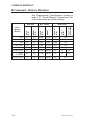
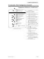
The following two tables help identify some of
the basic printer memory related features and
options.
SRAM
Nonvolatile Memory
LP2122
LP2142
LP2242
LP2622
LP2642
LP3642
TLP2242
TLP2622
TLP2642
TLP3642
TLP2046
980009-001 Rev.F
Internal (KB)
0
0
128
128-256
128
128
128
128-256
128
128
0
Standard
Configuration (KB)
128
128
128
128
128
256
128
128
128
256
128
With Cartridge
(KB)
128-512
128-512
256-512
N/A
256-512
256-512
256-512
N/A
256-512
256-512
128-512
1-5
PROGRAMMING CONSIDERATIONS
Flash
Nonvolatile Memory
2443 (Orion)
2684 (Strata)
2722
2742
3742
2746
2344 (Eclipse)
P2222
P2242
Flash
Standard
Maximum
512 KB
1 MB
512 KB
1 MB
512 KB
1 MB
512 KB
1 MB
1MB
—
512 KB
1 MB
512 KB
1.5MB
512 KB
512 KB
SRAM
Standard
Maximum
256 KB
512 KB
512 KB
1 MB
128 KB
256 KB
256 KB
512 KB
512 KB
1 MB
512 KB
1 MB
256 KB
384 KB
128 KB
160 KB
Printers with flash memory have a limited number of
write cycles. Limiting the number memory writes is essential to maximize flash memory life and is a good
practice in general. Some printers with flash memory
chips have flash write cycles limited to 100,000 cycles
before the storage of data may become unreliable.
All new Eltron brand printer models have flash memory to allow field upgrade of printer firmware by
downloading firmware directly into the printer.
The programmer should discriminately use
commands that write to memory. The following
commands write to flash memory:
❏ M command - Formats/Erases Memory.
❏ FS / FE / FK commands - The commands
initiates and enables form data writes to flash
memory or delete form from memory.
❏ ES / EK commands - The commands stores
soft font data writes to flash memory or deletes a soft font from memory.
❏ GM / GK commands - Sets and initiates
PCX graphic data writes into flash memory
or deletes a graphic from memory.
❏ D / S / O commands - Sets printer control
parameters will only write into flash memory
if the parameter has changed.
1-6
980009-001 Rev.F
PROGRAMMING CONSIDERATIONS
Status Reporting Status reporting commands provide the user
and programmer with printer operational
status, memory usage, and listings of forms and
graphics loaded into printer memory. The
status responses are for maintenance and program debugging.
Command
Description
EI
Print Soft Font Information
FI
Print Form Information
GI
Print Graphic Information
Page
2-15
2-18
2-24
2-53
U
Print (Printer) Configuration
G-17
Printer To Host Status - Serial Interface
Form Information Inquiry
G-21
UF
(Host)
Graphics Information Inquiry
G-22
UG
(Host)
Enable Host Prompts/Codepage
G-23
UI
Inquiry (Host)
UN
Disable Error Reporting
G-25
Enable Error Reporting
G-29
US
(Host)
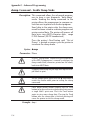
PROGRAMMING CAUTION:
Parallel Port Configurations and the UF, UG,
UI or US Commands: The printer only communicates a detailed status to the host via the printer’s serial port.
If the printer is only connected to the host via the
parallel port, DO NOT send a UF, UG, UI, or US
(Host) status reporting commands to the printer. The
printer may appear to hang. The user may have to
make a serial cable connection to the host or power
cycle the printer to resume normal printing
operations.
980009-001 Rev.F
1-7
PROGRAMMING CONSIDERATIONS
Command The manual uses the following typographic
Conventions conventions to describe commands.
Example
Description
A
Commands (Case Sensitive)
p1,p2,p3
Required parameters
[p1, p2, p3]
Optional parameters
{Choice 1|Choice 2}
Indicates a mandatory choice between two or more items. You
must include one of the items unless all of the items are also enclosed in square brackets.
This text should be →
on one line
The line-continuation character
(→) indicates that code is continued from one line to the next and
should be typed all on one line.
↵
Line feed character.
“NAME”
The name of a form or graphic in
double quote marks.
“DATA”
The text or bar code data in double quote marks.
The (\) character designates that
the character following is a literal
and will encode into the data
field. Refer to the following examples:
To Print
”
“Company”
\
\code\
“PROMPT”
Enter into Data Field
\"
\"Company\"
\\
\\code\\
An ASCII text field that will be
transmitted to the host (via the serial interface) each time this command is executed.
Attention!!
All commands and alpha character command
parameters are case sensitive!
1-8
980009-001 Rev.F
PROGRAMMING CONSIDERATIONS
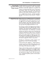
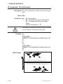
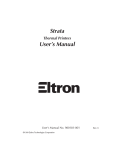
Basic Command Each command consists of one or two ASCII
Syntax (case sensitive) alpha characters to identify the
specific command desired. Some commands
require one or more additional parameters to
supply the printer with sufficient information to
complete the command. Refer to Figure 1-1 for
the basic command syntax.
Figure 1-1
Command Name
Basic Command
WRITE TEXT
Syntax
A p1,p2,p3,p4,p5,p6,p7,"DATA"↵
Command
Parameters
Command
Specific
Data
Each command line must be terminated with a
Line Feed (LF) character (Dec. 10). Most PC
based systems send CR/LF when the Enter key
is pressed. The Carriage Return (CR) character
is ignored by the printer and cannot be used in
place of LF.
980009-001 Rev.F
1-9
PROGRAMMING CONSIDERATIONS
Command Editor One method to create command files is through
an ASCII based text editor. In the DOS
environment, MS-DOS EDIT or BRIEF are
good choices. To execute the file, use the
editor’s print command or from the DOS
prompt, use the COPY command to send the
file directly to the printer. An example of the use
of the COPY command is:
COPY “FILENAME.EXT” LPT1↵
or
COPY “FILENAME.EXT” COM1↵
For more information on the use of the COPY
command, refer to your DOS software manual.
Configure the COM port to match the printer’s
serial port setting (typically set to defaults). See
the Y command in section 2 for details.
See Examples in Appendix H for more information
on downloading forms or graphics to an EPL2
printer.
1-10
980009-001 Rev.F
PROGRAMMING CONSIDERATIONS
Printer Memory The EPL2 printers feature nonvolatile memory
Organization for storage of label forms, graphics and soft
fonts. This memory can be located in the
printer, in removable memory cartridges or
both depending upon the printer model.
Many EPL2 printers require the use of the M
command to specify the amount of memory allotted to memory storage groups: image buffer,
forms, graphics and soft fonts. See the M command in Section 2, Command Reference, for
memory management details by printer model.
Each time the memory allocation command M
is used; forms, graphics and soft fonts stored in
memory are erased. Because previously stored
forms, graphics and fonts are deleted by the M
command, extra care should be used when formatting printer memory.
Printers with Flash Memory
Printers with flash memory do not require memory
partitioning for storage of forms, graphics, soft fonts
or the image buffer as required by other EPL2 printers. However, the M command is required to format/clear existing memory. See the M command in
Section 2 for details.
Forms Form (or command) files can be downloaded to
memory for storage and later recall. A form can
contain fixed text, variable text (entered at print
time), counters (recalled or entered at print
time) and bar code symbols. A form can call a
graphic from memory and use the graphic as
part of the form.
The number of stored forms allowed is dependent on the amount of memory available in the
nonvolatile printer memory
Graphics Graphic image data and forms are stored in the
nonvolatile memory. The number of graphics
that printer memory can hold is strictly dependent upon print memory availability.
980009-001 Rev.F
1-11
PROGRAMMING CONSIDERATIONS
Soft Fonts Soft Font data is stored in nonvolatile memory.
Up to 52 soft fonts, can be loaded into printer
memory (and recalled as A-Z, a-z; see Section 2,
Command Reference). The number of soft
fonts that printer memory can hold is strictly dependent upon print memory availability. Easily
download soft font data to the nonvolatile
memory with programs such as Soft Font
Downloader Utility, CAL Tools and Create-ALabel 3.
Image Buffer The Image Buffer is the assembly area for label
elements (text, lines, bar codes, graphics, etc.),
prior to printing. Each label element is added to
the image (label) buffer, command by command, as processed by the printer.
The printer must have enough image buffer
memory available to hold the largest label/form
image to be printed. This depends on the label
size (length and width). The image buffer length
and width are set by the Q and q commands,
respectively.
1-12
980009-001 Rev.F
PROGRAMMING CONSIDERATIONS
Image Buffer The printer allocates image buffer memory usAddressing ing the stored values for length and width. The
default length of the image buffer is set by the
EPL2 printer’s AutoSense feature. The default
image buffer width is the print head width in
dots. The width of the print head is measured in
dots per inch (dpi) or dot per millimeter
(dot/mm).
❏ 2 inch printers - the maximum print width is
2.20 inches (54 mm) at 203 dpi (8 dot/mm)
resolution.
❏ 2 inch P2222 (Xport) - the maximum print
width is 2.00 inches (48 mm) at 203 dpi (8
dot/mm) resolution.
❏ 4 inch printers (200 dpi models) The maximum print width is 4.09 inches
(104 mm) at 203 dpi (8 dot/mm) resolution.
❏ 4 inch printers (300 dpi) The maximum print width is 4.09 inches
(104 mm) at 300 dpi (11.8 dot/mm) resolution.
❏ 2684 (Strata) - the maximum print width is
8.5 inches (216 mm) at 203 dpi (8 dot/mm)
resolution.
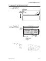
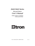
When placing objects in the image buffer for
printing, the address locations are expressed in
dots on an X-Y grid. The X value represents the
width and the Y value represents the height of
the grid. The point of origin (the starting point)
for a non-rotated object is the upper left corner.
As an object rotates, the point of origin rotates
with the object.
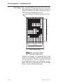
These image buffer properties are depicted
graphically in the following illustration.
980009-001 Rev.F
1-13
PROGRAMMING CONSIDERATIONS
Sample Format
"q" dots
x axis
y axis (0,0)
Text
Text
Text
Point of
Origin for
Text Object
Point of
Origin for
BarCode Object
Direction Of Feed
Point of
Origin for
Text Object
Rotated 90°
"Q"
dots
Point of
Origin for
Text Object
Rotated 270°
The minimum non printing margin on all edges
of the label is 1mm. Printing closer than 1mm to
the top or bottom edge of the label may cause
the printer to advance unwanted labels or cause
the printer to go into error condition.
Installed Memory vs. The maximum size of an image buffer is deForm Length pendent upon the amount of SRAM available to
create a single image buffer. Increasing SRAM
memory increases the total memory available
for image buffer creation. Most EPL2 printers
have memory expansion options. The recommended minimum amount of available image
buffer memory is two (2) times the size of the
largest label/form image to be printed (plus 10
Kbytes for internal printer operation).
Printers that have SRAM memory only, share
memory with the storage of form, graphic and
soft font data. Printers with flash memory use
the SRAM for image creation and store data in
flash memory.
1-14
980009-001 Rev.F
PROGRAMMING CONSIDERATIONS
A small amount of SRAM memory is used to operate and temporarily store variables (counters,
text variables, control parameters, etc.) needed
to print. See the formulas on page which account for this additional SRAM requirement.
The following tables outline the memory
required to print two (2) images of various sizes.
203 dpi Printers
Image Buffer Size
(Kbytes)
Width
in inches
1.20
1.25
2.25
2.25
2.25
2.25
2.25
4.00
4.00
4.00
4.00
4.00
4.00
8.50
q value
in dots
244
254
457
457
457
457
457
812
812
812
812
812
812
1726
Height
in inches
0.85
1.00
0.75
1.25
2.00
3.00
4.00
1.00
1.50
3.00
4.00
5.00
6.00
11.00
Q value
in dots
173
203
152
254
406
609
812
203
305
609
812
1015
1218
2233
Single
6
7
10
15
24
35
47
22
32
63
83
103
124
479
Double
12
14
19
30
47
70
93
43
64
125
165
206
247
957
300 dpi Printers
Image Buffer Size
(Kbytes)
Width
in inches
1.25
2.25
2.25
2.25
2.25
2.25
4.16
4.00
4.00
4.00
4.00
4.00
980009-001 Rev.F
q value
in dots
375
675
675
675
675
675
1248
1200
1200
1200
1200
1200
Height
in inches
1.00
0.75
1.25
2.00
3.00
4.00
1.00
1.50
3.00
4.00
5.00
6.00
Q value
in dots
300
225
375
600
900
1200
300
450
900
1200
1500
1800
Single
15
20
33
51
76
101
48
69
135
180
224
269
Double
29
40
65
102
152
202
96
137
270
359
448
537
1-15
PROGRAMMING CONSIDERATIONS
Double Buffering EPL2 printers with firmware version 3.0 and
higher (except TLP2046) support double buffering of print images to increase through-put.
The printer can print the image out of one buffer
while loading an image into a second image
buffer, if sufficient memory is available to load
the second image. The printer will automatically
test and enable double buffering. Double buffering allows the printer with most image formats
to print continuously.
If a sufficient amount of image buffer memory is not
available to double buffer print images, then the
printer will load a print image and then print, performing these functions one label at a time.
While operation of the Double Buffering feature
is automatic, the following are requirements to
enable the feature:
❏ The Q command must be used to establish
the height of each label and initiate double
buffering.
❏ The q command must be used to match the
width of the image buffer to the width of the
label. The q command will maximize and test
the image buffer if sufficient memory is available to enable double buffering.
❏ The amount of (SRAM) memory allocated
(with the M command) for the image buffer
must be large enough to hold the two label
images. Using the formulas below, calculate
the memory requirements for each label.
Add the memory requirements for each label
to determine the total image buffer memory
requirements.
Flash Memory Printers - The M command does
not affect the image buffer size in flash memory
based printers. The image buffer is a fixed size.
1-16
980009-001 Rev.F
PROGRAMMING CONSIDERATIONS
The q value affects the available print width. Minimizing the q value will maximize the print length and
print speed (double buffering).
Use the appropriate dot measurement conversion to determine the image buffer size with the
following formulas:
For 203 dots per inch (8 dots per mm) printers;
OR
For 300 dots per inch (11.8 dots per mm) printers:
Single Buffer
(Height in dots[Q]+10) x Width in dots[q]/8096=KBytes required
Double Buffer
([Single Buffer Kbytes Required] x 2) + 0.5 =KBytes required
When receiving data for a new label, the printer
checks the size of each new label and the previous label size to determine if both images will fit
into the image buffer. If so, processing of the
second label will continue even if the first label is
printed.
To determine the maximum memory required to
print labels continuously with double-buffering, the
programmer should add the print buffer requirements of the two (2) largest consecutive print images
together.
980009-001 Rev.F
1-17
PROGRAMMING CONSIDERATIONS
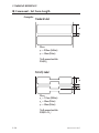
Text (Fonts) The standard EPL2 printer has five (1-5) resident mono-spaced dot fonts. Fonts A-Z and a-z
(upper and lower case alpha characters) are reserved for downloading soft fonts.
First Character of Text String Reference Point
12
D
o
t
s
8 Dots
Character Width
Total Character Width
Inter-character Space
(actually white dots)
Control text height (in horizontal dots) and
width (in vertical dots) with the horizontal and
vertical multipliers. The text is oriented first and
then the A command’s font multipliers are applied. The text is then placed into the image
buffer. See the following example.
1-18
980009-001 Rev.F
PROGRAMMING CONSIDERATIONS
Horizontal Dots
x axis
y axis (0,0)
Text
Text - No Size Multipliers
2x Horizontal Multiplier
Text
Text
Point of
Origin for
Text Object
2x Vertical Multiplier
Point of
Origin for
Text Object
Text
Text
Point of
Origin for
Text Object
Point of
Origin for
V Text Object
e Rotated 90°
r
t
i
c
a
l
D
o
t
s
Direction Of Feed
Point of Origin
for Text Object
Rotated 270°
The reference point of the first character in a text
string is not affected by the font size multiplier values.
First Character of Text
String Reference Point
2 times
980009-001 Rev.F
2 times
1-19
PROGRAMMING CONSIDERATIONS
Bar Codes All bar codes supported by the EPL2 language
have associated industry specifications that the
programmer should be aware of and adhere to.
The programmer needs to consider bar code
features and requirements when choosing and
using a bar code for different applications.
Some of the features and requirements that
need consideration are listed below:
❏ Data used by the application are per the bar
code specification (numbers only, alphanumeric, alphanumeric and special characters,
etc.).
❏ Minimum and maximum number of characters allowed or required per bar code.
❏ Density or magnification of a given bar code
type.
❏ White area required around bar codes (the
“Quiet Zone”).
❏ The bar code must print within the image
buffer (printable area of the label).
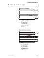
Bar Code Orientation Tip
To help ensure that generated bar codes are readable by the widest variety of bar code readers, print
bar codes in the “Picket Fence” orientation versus
the “Ladder” orientation.
Horizontal Dots
x axis
y axis (0,0)
Height of
Bar Code
Height of
Bar Code
V
e
r
t
i
c
a
l
Picket Fence
Orientation
Ladder
Orientation
D
o
t
s
Direction Of Feed
1-20
980009-001 Rev.F
PROGRAMMING CONSIDERATIONS
Programming Graphic elements can interact and the resultant
Sequences Affect image can be affected by other commands.
Graphic Results Structure command sequences to reduce the
chances of unexpected print results. The printer
will process lines, text, boxes and most bar
codes in command sequence. The printer then
processes the printer control processes, counters, variable data, Postnet, and then graphics
last. See the programming examples in Appendix H.
Media Detection Media detection in EPL2 printers is a combination of programming and printer media sensing.
The Q (Set Form Length) and O (Option) commands program the media detection method.
The user must configure the printer for the media type and the programmed form in use.
The printer can detect the beginning and end of
the printable area on the media by one of three
methods: Gap, Notch (hole), or Black line. The
Gap method detects the difference in optical
density of a label on a liner from the liner only
with the Transmissive (Gap) sensor. The Notch
method uses the Transmissive sensor to detect a
hole in the media (gap-less labels or tag stock).
The Black line method uses the Reflective sensor to detect a preprinted black line on the media back (for gap-less labels or tag stock).
Printing on continuous media requires programming to control media positioning.
EPL2 printers also support a “Label Dispense”
mode as a printer configuration option (for most
models). The printers use a “Label Taken” sensor to detect the removal of a label.
One or more of these sensors may require user
adjustment or configuration for proper operation. All EPL2 printers have an AutoSense feature to optimize label and label gap detection by
the transimissive (gap) sensor. See the printer’s
user’s manual for printer specific sensor adjustment control.
980009-001 Rev.F
1-21
PROGRAMMING CONSIDERATIONS
Determining Printer The printer version numbers are a code used to
Firmware Version document product function and the feature
support level of the printer. To check the firmware version installed in your printer, perform
the AutoSense procedure described in the
printer’s user’s manual or via the printer interface by issuing a programming U command.
1-22
980009-001 Rev.F
COMMAND REFERENCE
COMMAND REFERENCE
This section contains a complete listing of
printer commands in alphabetical order and describes the basic commands.
980009-001 Rev.F
2-1
COMMAND REFERENCE
A
B
b
C
C
D
EI
EK
eR
ES
f
FE
FI
FK
FR
FS
GG
GI
GK
GM
I
JB
JF
LE
LO
LS
LW
M
N
O
o
oB
2-2
ASCII Text
Bar Code
2D Bar Code
Counter
Cut Immediate
Density
Print Soft Font Info.
Delete Soft Font
User Definable Error Response
Store Soft Font
Cut/Peel Position
End Form Store
Print Form Info.
Delete Form
Retrieve Form
Store Form
Retrieve Graphics
Print Graphics Info.
Delete Graphic
Store Graphic
Character Set Selection
Disable Top Of Form Backup
Enable Top Of Form Backup
Line Draw Exclusive
Line Draw Black
Line Draw Diagonal
Line Draw White
Memory Allocation
Clear Image Buffer
Options Select
Cancel Customized Settings
Cancel Customize Bar Code
✔
✔
✔
✔
✔
✔
✔
✔
✔
✔
✔
✔
✔
✔
✔
✔
✔
✔
✔
✔
✔
✔
✔
✔
✔
✔
✔
✔
✔
✔
✔
✔
✔
✔
✔
✔
✔
✔
✔
Pa
ge
d
No
t
pp
ort
e
Su
eci
fic
Sp
Description
AL
L
Co
m
ma
nd
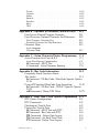
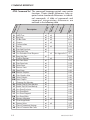
EPL2 Command Set The command language controls most printer
functions. Printer model differences have required minor functional differences to individual commands. A table of commands and
command interpretation differences are
outlined in the following table.
2-4
2-7
D-15
2-11
F-3
2-14
2-15
H-35
See Appendix G G-7
H-36
F-4
2-17
2-18
2-19
2-20
2-21
2-23
2-24
2-25
2-26
2-28
2-29
2-29
2-30
2-31
2-32
2-33
2-34
2-38
2-39
G-9
G-10
980009-001 Rev.F
oH
oM
oW
P
p
PA
Q
q
r
R
S
TD
TS
TT
U
Ux
V
W
xa
X
Y
Z
?
^@
^ee
Macro PDF Offset
Disable Initial Esc Sequence Feed
Customize Bar Code Parameters
Print
Reset Top of Form Sensing
Print Automatic
Set Form Length
Transmissive (Gap) Sensor
Black Line Sensor
Continuous Stock
Set Form Width
Buffer Mode
Set Reference Point
Speed Select
Define Date Layout
(& Print Date)
Set Real Time Clock
Define Time Layout
(& Print Time)
Print Configuration
Status, Debug & Inquiry (Serial Port
Only) - UA, UB, UE, UF, UG, UI,
UM, UN, UP, US
Define Variable
Windows Mode
Sense Media
Box Draw
Serial Port Setup
Print Direction
Download Variables
Reset Printer
Status Report - Immediate
✔
✔
✔
✔
Pa
D-27
2-41
G-10
2-42
G-15
2-43
✔
✔
✔
2-44
✔
✔
✔
2-48
G-16
2-50
2-52
✔
✔
✔
ge
d
No
t
pp
ort
e
Su
eci
fic
Sp
Description
AL
L
Co
m
ma
nd
COMMAND REFERENCE
✔
✔
✔
✔
2022//2042
2622
P2222
2344 (Eclipse)
E-5
E-6
E-7
✔
2-53
✔
✔
See Appendix G G-17
✔
✔
✔
✔
✔
✔
✔
✔
2-58
G-30
Flash
SRAM
G-31
2-59
✔
2-60
2-62
2-63
G-33
✔
See Appendix G G-32
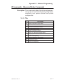
ALL - Commands that function the same for all models.
Specific - Commands that require special programming considerations (other than print
width) for printer model variations, such as dot per inch, printing speed or memory partitioning.
Not Supported - Are commands that are ignored by the model(s) listed.
980009-001 Rev.F
2-3
COMMAND REFERENCE
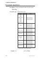
A Command - ASCII Text
Description Prints an ASCII text string
Syntax Ap1,p2,p3,p4,p5,p6,p7,"DATA"
Parameters p1 = Horizontal start position (X) in dots.
p2 = Vertical start position (Y) in dots.
p3 = Rotation
Value
0
Description
No rotation
1
90 degrees
2
180 degrees
3
270 degrees
p4 = Font selection
Value
1
Description
203 dpi
300 dpi
20.3 cpi, 6 pts,
25 cpi, 4 pts,
(8 x 12 dots)
(12 x 20 dots)
2
16.9 cpi, 7 pts,
(10 x 16 dots)
18.75 cpi, 6 pts,
(16 x 28 dots)
3
14.5 cpi, 10 pts,
(12 x 20 dots)
15 cpi, 8 pts,
(20 x 36 dots)
4
12.7 cpi, 12 pts,
(14 x 24 dots)
12.5 cpi, 10 pts,
(24 x 44 dots)
5
5.6 cpi, 24 pts,
(32 x 48 dots)
6.25 cpi, 21 pts,
(48 x 80 dots)
Reserved for
Soft Fonts
Reserved for
Soft Fonts
A-Z
Fonts 1 - 5 are fixed pitch. See Appendix A
and B for printer character map support.
See Appendix C for Asian Character support.
p5 = Horizontal multiplier, expands the text
horizontally. Values: 1, 2, 3, 4, 5, 6, & 8.
p6= Vertical multiplier, expands the text vertically. Values: 1, 2, 3, 4, 5, 6, 7, 8, & 9.
p7 = N for normal or R for reverse image
“DATA” = Represents a fixed data field.
2-4
980009-001 Rev.F
COMMAND REFERENCE
A Command - ASCII Text
The backslash (\) character designates the
following character is a literal and will encode
into the data field. Refer to the following examples:
To Print
“
“Company”
\
\code\
Enter into data field
\”
\”Company\”
\\
\\code\\
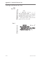
Examples: ¿
N¿
A50,0,0,1,1,1,N,"Example 1"
A50,50,0,2,1,1,N,"Example 2"¿
A50,100,0,3,1,1,N,"Example 3"¿
A50,150,0,4,1,1,N,"Example 4"¿
A50,200,0,5,1,1,N,"EXAMPLE 5"¿
A50,300,0,3,2,2,R,"Example 6"¿
P1¿
Will Produce:
As shown in example 5 above, font 5 only supports
upper case characters. Refer to Appendix A for a
complete listing of available fonts and character sets
supported.
980009-001 Rev.F
2-5
COMMAND REFERENCE
A Command - ASCII Text
The data field can be replaced by or combined
with the following commands:
Vnn= Prints the contents of variable “nn” at
this position where nn is a 2 digit
number from 00 to 99.
Cn= Prints the contents of counter “n” at this
position where n is a one digit number
from 0 to 9.
See Appendix E for additional Data
parameters for printers with the RTC (real time
clock) option installed.
Examples: A50,0,0,1,1,1,N,"DATA"¿ : Writes Text
A50,50,0,2,1,1,N,V01¿
: Writes contents of variable 01
A50,100,0,3,1,1,N,C1¿
: Writes contents of counter 1
A50,100,0,3,1,1,N,C1+2¿ : Writes contents of counter 1 plus 2
Use the LE command to create reverse print text instead of the “R” in the A command parameter p7.
This is the recommend method because it provides
the best size, position and centering of the black line
(rectangle) bordering the reversed text.
2-6
980009-001 Rev.F
COMMAND REFERENCE
B Command - Bar Code
Description Use this command to print standard bar codes.
Syntax Bp1,p2,p3,p4,p5,p6,p7,p8,"DATA"
Parameters p1 = Horizontal start position (X) in dots
p2 = Vertical start position (Y) in dots.
p3 = Rotation
Value
0
Description
No rotation
1
90 degrees
2
180 degrees
3
270 degrees
p4 = Bar Code selection (see Table 2-1 on
next page).
p5 = Narrow bar width in dots. (see Table
2-1 on next page).
p6 = Wide bar width in dots. Acceptable values are 2-30.
p7 = Bar code height in dots.
p8 = Print human readable code.
Values: B=yes or N=no.
“DATA” = Represents a fixed data field. The
data in this field must comply with the selected
bar code’s specified format. See Appendix D for
more information on bar codes.
The backslash (\) character designates the
following character is a literal and will encode
into the data field. Refer to the following examples:
To Print
“
“Company”
\
\code\
980009-001 Rev.F
Enter into data field
\”
\”Company\”
\\
\\code\\
2-7
COMMAND REFERENCE
B Command - Bar Code
Bar Codes
Code 39 std. or extended
P4
Value
3
P5
Value
1-10
Code 39 with check digit
3C
1-10
9
1-10
Code 128 UCC
Serial Shipping Container Code
0
1-10
Code 128 auto A, B, C modes3
1
1-10
Codabar
K
1-10
EAN8
E80
2-4
EAN8 2 digit add-on
E82
2-4
EAN8 5 digit add-on
E85
2-4
EAN13
E30
2-4
EAN13 2 digit add-on
E32
2-4
EAN13 5 digit add-on
E35
2-4
German Post Code
2G
3-4
2
1-10
Interleaved 2 of 5 with mod 10
check digit
2C
1-10
Interleaved 2 of 5 with human
readable check digit1
2D
1-10
Postnet 5, 6, 8 & 9 digit
P
—
UCC/EAN 128
1E
1-10
UPC A
UA0
2-4
UPC A 2 digit add-on
UA2
2-4
UPC A 5 digit add-on
UA5
2-4
UPC E
UE0
2-4
UPC E 2 digit add-on
UE2
2-4
UPC E 5 digit add-on
UE5
2-4
UPC Interleaved 2 of 5
2U
L
M
1-10
—
—
Description
Code 93
3
Interleaved 2 of 5
Plessey (MSI-1) with mod. 10 check digit2
MSI-3 with mod. 10 check digit2
Note 1 - Not supported by some older model printers. Test
before using this option. Upgrades may be available.
Note 2 - P2242 & P2222 only
Note 3 - Manual selection of A,B or C modes is not supported
2-8
980009-001 Rev.F
COMMAND REFERENCE
B Command - Bar Code
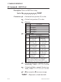
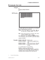
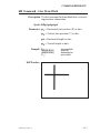
Example: ¿
N¿
B10,10,0,3,3,7,200,B,"998152-001"¿
P1¿
Will Produce:
The data field can be replaced by or combined
with the following commands:
Vnn =Prints the contents of variable “nn” at
this position. Range of nn = 00 to 991.
Cn =Prints the contents of counter “n” at this
position. Range of n = 0 to 9
See Appendix E for additional Data parameters for printers with the RTC (real time clock)
option installed.
Examples: B50,0,0,3,1,2,50,B,"DATA"¿ : Writes bar code
B50,50,0,3,1,2,50,N,V01¿ : Writes contents of variable 01 as bar
: code
B50,50,0,3,1,2,50,N,C1¿ : Writes contents of counter 1 as bar code
B50,50,0,3,1,2,50,N,C1+2¿: Writes contents of counter 1 plus2 as
: bar code
or a combination of several options:
B50,300,0,3,1,2,50,B,"Deluxe"V01C2"Combo"V01¿
:Writes the text “Deluxe” followed by the contents of variable 01 followed by the contents of counter 2 followed by the text “Combo” followed by the contents of variable 01 all as a code 39 bar code.
1
Version 2.23 and above.
980009-001 Rev.F
2-9
COMMAND REFERENCE
b Command - 2D Bar Code
Description Print 2D Bar Code - This command will direct a
printer equipped with the 2D bar code feature
to print a two (2) dimensional bar code type.
This command is listed here for reference only. See
Appendix D-15 for details about two dimensional
(2D) bar codes and command structure supported
by most Eltron printers.
Syntax bp1,p2,p3, [code specific options]
Parameters p1 = Horizontal start position (X) in dots
p2 = Vertical start position (Y) in dots
p3 = 2-dimensional bar code type
Value
M
Code Type
MaxiCode1
P
PDF417
Note 1: The MaxiCode specification has
been released.
The following table outlines printer support for
the 2D bar codes and the b command.
Model
2046
2122
2142
All other models
MaxiCode
S
S
S
S
PDF417
O
O
O
S
O = Option; S = Standard
2-10
980009-001 Rev.F
COMMAND REFERENCE
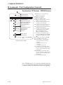
C Command - Counter
Description The command defines one of 10 automatic
counters used in consecutive numbering
applications (i.e. serial numbers).
For Numeric Serialization Only. The counter
function does not support Alpha or Alpha-Numeric
Serialization.
Syntax Cp1, p2, p3, p4, “[-][--]PROMPT”
Parameters p1 = Counter number.
Range: 0 to 9
p2 = Maximum number of digits for the counter.
Range: 1 to 29
p3 = Field Justification.
L = Left
R = Right
C = Center
N = No Justification
p4 = Step Value. + or - sign followed by a
single digit of 1 - 9. Using a step value of
+0 allows the counter to be used as an
additional variable data field.
“PROMPT”= An ASCII text field that will be
transmitted to the KDU or host (via the
serial interface) each time the command
is executed. Typically used to request the
operator to enter a starting counter value.
KDU Prompt [-] = Having the first character of the promt a
single minus sign will cause the prompt
Options
to display only once after form retrieval.
[--]= Two minus signs (with no space between) as the first two characters of the
prompt field will cause the prompt to be
suppressed. This option is not directly
supported by flash printers.
See “Saving and Protecting Consecutive Numbers
in Nonvolatile Memory” for additional usage of the
- and - - PROMPT options.
980009-001 Rev.F
2-11
COMMAND REFERENCE
C Command - Counter
The C command is used in forms that require sequential numbering. When initializing counters,
they must be defined in order (e.g. C0 first, C1
second...).
Field justification (p3) affects the printing of
counter data. When L, R or C are selected, the
counter field is the width of p2 value. Data will
justify within the counter (p2) field per the selected p3. The N parameter will print the minimum number of characters. See programming
example 13 in Appendix H.
To print the contents of the counter, the counter
number is referenced in the “DATA” field of the
A (ASCII text) or B (Bar Code) commands.
If the starting value of a counter is “1", then no leading zero padding will be added. If the starting value is
“01”, then the counter will be padded, up to the
maximum number of digits (p2), with zeros. Counters must be defined after variables.
Example: C0,10,L,+1,"-Enter Serial Number:"¿
By placing two minus signs as the first two characters of the prompt, the prompt will never be
displayed.
Example: C0,10,L,+1,"- -Enter Serial Number:"¿
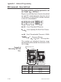
To edit or restart a protected consecutive number, the KDU’s form edit function must be used.
From the “FORM - retrieve form prompt”, perform the
following steps:
1. Press F1.
2. Press 4 9 1 6
3. Press the FORM key.
4. Key in the form name and press ENTER to retrieve.
5. Enter or modify the consecutive number.
6. When complete, print the form to store the new number in memory.
2-12
980009-001 Rev.F
COMMAND REFERENCE
C Command - Counter
Saving and
Protecting
Consecutive
Numbers in
Nonvolatile Memory
This feature is useful when the counter field represents a serial number (or others types of numbers) that should never be repeated. This
feature allows for automatic retrieval and incrementing (or decrementing) of the previous
counter value used every time a form is retrieved (and printed).
By placing one minus sign as the first character
of the prompt, the prompt will appear only once
after the form is retrieved, thereby protecting
the integrity of the data.
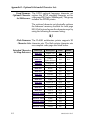
KDU Support: This table shows individual printer support for
internal storage of counter data.
Model
2622, 2642 (2242), 3642
2122, 2142
2046 / 2044
2443 (Orion)
2722 / 2742
2344 (Eclipse), 2746
2684 (Strata)
P2242 / P2222
Counter Data Storage Options
C
-S
S
S
S
S
S
S
S
S
Note 1
Note 1
N/A
Note 1
Note 1
N/A
Note 1
Note 1
N/A
Note 1
Note 1
N/A
Note 1
Note 1
N/A
O = Option; S = Standard; N/A = Not Supported
Note 1 – Internally stored counter values are reset after cycling
printer power or sending a reset command or pressing the Cancel.
Flash Memory Printers - Storing counter values
(after power is cycled or a Reset) and the [- -]
prompt option are only supported with KDUs built
after December 1999. These KDUs store the counter
data for later recall.
Single Digit Add or substract a single digit from the recalled
Summation with counter value in a form. If form recalled counter
Counters C0 had a value of 3, then processing C0+1 or
C0-2 would yeild values of 4 and 1 respectively.
980009-001 Rev.F
2-13
COMMAND REFERENCE
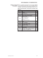
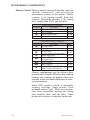
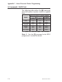
D Command - Density
Description Use this command to select the print density.
Syntax Dp1
Parameters p1 = Density setting. Acceptable values are:
Model
20X2
21X2
2622
2642 (2242)
3642
2722
2742
3742
2443 (Orion)
2344 (Eclipse)
2046 / 2044
2746
2684 (Strata)
P2222
P2242
Acceptable Values1
0-7
0-7
0 - 15
0 - 15
0 - 15
0 - 15
0 - 15
0 - 15
0 - 15
0 - 15
0 - 15
0 - 15
0 - 15
0 - 15
0 - 15
Default Value
2
2
7
7
7
7
7
7
10
5
5
7
7
8
6
Note 1: 0 is the lightest print and 7 or 15 is the darkest.
The density command controls the amount of
heat produced by the print head. More heat will
produce a darker image. Too much heat can
cause the printed image to distort.
The P2222 set to “0” density (D0) will automatically
enable a 2.0ips speed if the battery power level will
support the 2.0ips speed.
The density and speed commands can dramatically
affect print quality. Changes in the speed setting typically require a change to the print density.
Example: D5↵
2-14
: selects density 5
980009-001 Rev.F
COMMAND REFERENCE
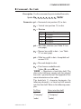
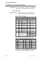
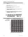
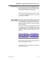
EI Command - Print Soft Font Information
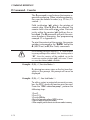
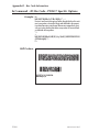
Description This command will cause the printer to print a
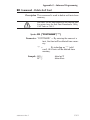
list of all soft fonts that are stored in memory.
Syntax EI↵
Soft fonts can be downloaded to and deleted from
the printer from the Soft Font Downloader Utility,
CAL Tools or CAL3.
See Appendix G, Advanced Programming, for details on the programming and commands to directly
format, download and delete soft fonts.
Example: EI↵
:prints soft font list
Will Produce:
980009-001 Rev.F
2-15
COMMAND REFERENCE
EK Command - Delete Soft Font
See Appendix G
ES Command - Store Soft Fonts
See Appendix G
2-16
980009-001 Rev.F
COMMAND REFERENCE
FE Command - End Form Store
Description This command is used to end a form store sequence.
Syntax FE
Example: FS"FORMNAME"↵
...
FE↵
The form store sequence is started with the FS
command.
980009-001 Rev.F
2-17
COMMAND REFERENCE
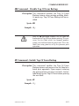
FI Command - Print Form Information
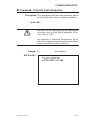
Description This command will cause the printer to print a
list of all forms stored in memory.
Syntax FI
Example: FI↵
:prints forms list
Will Produce:
2-18
980009-001 Rev.F
COMMAND REFERENCE
FK Command - Delete Form
Description This command is used to delete forms from
memory.
Syntax FK {“FORMNAME”|"*"}
Parameters “FORMNAME” = By entering the name of a
form, that form will be deleted from
memory.
· The name may be up to 8 characters long.
· Form names stored by the printer are case
sensitive and will be stored exactly as entered
on the FS command line; i.e. “FORM1”,
“form1” and “FoRm1” are three different
forms when stored into the printer or when
retrieved by the user.
“*” = By including an “*” (wild card), ALL
forms will be deleted from memory.
Example: FK"AFORM"↵
FK"AFORM"↵
:deletes form “AFORM”
:second delete form “AFORM” required
:for flash printers
FK"*"↵
:deletes all forms
Flash Memory Printers
Sin g le fo rm k ill o p era tio n s req u ire t he
FK”FORMNAME” be issued twice for each form
killed. The FK”*” does not require this second form
kill command line.
980009-001 Rev.F
2-19
COMMAND REFERENCE
FR Command - Retrieve Form
Description Use this command to retrieve a form that was
previously stored in memory.
Syntax FR"FORMNAME"
Parameters “FORMNAME” = This is the form name
used when the form was stored.
· The name may be up to 8 characters long.
· Form names stored by the printer are case
sensitive and will be stored exactly as entered
on the FS command line; i.e. “FORM1”,
“form1” and “FoRm1” are three different
forms when stored into the printer or when retrieved by the user.
Example: FR"TEST1"
:retrieves the form named TEST1
To print a list of the forms currently stored in
memory, use the FI command.
2-20
980009-001 Rev.F
COMMAND REFERENCE
FS Command - Store Form
Description This command begins a form store sequence.
Syntax FS"FORMNAME"
Parameters “FORMNAME” =This is the form name that
will be used when retrieving the stored
form.
· The name may be up to 8 characters long.
· Form names stored by the printer are case
sensitive and will be stored exactly as entered
on the FS command line; i.e. “FORM1”,
“form1” and “FoRm1” are three different
forms when stored into the printer or when retrieved by the user.
· Global commands such as EI, EK, ES, FI,
FK, GI, GK, GM, I, M, N, P, TS, U, UE,
UF, UG, Y, W, ?, ^@ should not be used in
a form store sequence.
Form name, AUTOFR, is reserved for automatic,
single form recall, see Appendix G, Advanced Programming, for details on this programming feature.
All commands following FS will be stored in
forms memory until the FE command is received, ending the form store process.
Delete a form prior to updating the form by
using the FK command.
If a form (with the same name) is already stored
in memory, issuing the FS command will result
in an error and the previously stored form is
retained.
To print a list of the forms currently stored in
memory, use the FI command.
980009-001 Rev.F
2-21
COMMAND REFERENCE
FS Command - Store Form
Example: ¿
FK"TESTFORM"¿
FS"TESTFORM"¿
:delete form “TESTFORM”
:begins the form store sequence of
:the form “TESTFORM”
V00,15,N,"Enter Product Name:"¿
B10,20,0,3,2,10,100,B,"998152.001"¿
A50,200,0,3,1,1,N,"Example Form"¿
A50,400,0,3,1,1,N,"Model Name: “V00¿
FE¿
FI¿
:ends form store sequence
:prints list of stored forms
A form will not store if sufficient memory is not allocated to form memory. See the M command for details on adjusting and configuring memory to store
forms (graphics and soft fonts).
2-22
980009-001 Rev.F
COMMAND REFERENCE
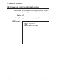
GG Command - Print Graphics
Description Use this command to print a PCX (format)
graphic that has been previously stored in
printer memory.
Syntax GGp1,p2,{"NAME" | Variable Data}
Parameters p1 = Horizontal start position (X) in dots.
p2 = Vertical start position (Y) in dots.
“NAME” or Variable Data = This is the
graphic name used when the graphic
was stored. This name can be supplied
via variable data (V00 - V99).
· The name may be up to 8 characters long.
· Graphic names stored by the printer are case
sensitive and will be stored exactly as entered
w ith th e GM co mma n d lin e; i. e .
“GR APHIC1”, “g ra p hic1” a nd
“graPHic1” are three different graphics
when stored into the printer or when retrieved
by the user.
Example: GG50,50,"LOGO1"↵
FK"TESTFORM"¿
FS"TESTFORM"¿
:delete form “TESTFORM”
:begins the form store sequence of
:the form “TESTFORM”
V00,8,N,"Enter Graphic Name:"¿
GG50,50,V00↵
FE¿
:ends form store sequence
FR¿
:ends form store sequence
980009-001 Rev.F
FR"TESTFORM"
?¿
LOGO1
:printed
:retrieves the form named TESTFORM
:Download variables
:Graphic name to be recalled and
P1¿
:Print one label with graphic LOGO1
2-23
COMMAND REFERENCE
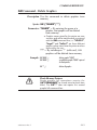
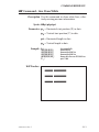
GI Command - Print Graphics Information
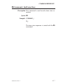
Description This command will cause the printer to print a
list of all graphics stored in memory.
Syntax GI
Example: GI↵
:prints graphics list
Will Produce:
2-24
980009-001 Rev.F
COMMAND REFERENCE
GK Command - Delete Graphics
Description Use this command to delete graphics from
memory.
Syntax GK {“NAME”|"*"}
Parameters “NAME” = By entering the name of a
graphic, that graphic will be deleted
from memory.
· Graphic names stored by the printer are case
sensitive and will be stored exactly as entered
with the GM command line; i.e. “LOGO1”,
“logo1” and “LoGo1” are three different
graphics when stored into the printer or when
retrieved by the user.
“*” = By including an “*” (wild card), ALL
graphics will be deleted from memory.
Example: GK"LOGO"↵
GK"LOGO"↵
:deletes graphic “LOGO”
:second delete graphic “LOGO” required
:for flash printers.
GK"*"↵
:deletes all graphics
Flash Memory Printers
Single graphic kill operations require the
GK”FORMNAME” be issued twice for each form
killed. The GK”*” does not require this second
graphic kill command line.
980009-001 Rev.F
2-25
COMMAND REFERENCE
GM Command - Store Graphics
Description Use this command to store PCX graphics files in
memory.
Syntax GM"NAME"p1¿
“DATA”
Parameters “NAME” = This is the graphic name that will
be used when retrieving the stored
graphic.
· The name may be up to 8 characters long.
· Graphic names stored by the printer are case
sensitive and will be stored exactly as entered
with the GM command line; i.e. “LOGO1”,
“logo1” and “LoGo1” are three different
graphics when stored into the printer or when
retrieved by the user.
p1 = This is the file size in bytes. Use the DOS
DIR command to determine the exact file
size.
“DATA” = Graphic data in 1-bit (black &
white) PCX (binary data) format file.
Example: GK"LOGO1"↵
GM"LOGO1"584↵
:“LOGO1”
DATA
:deletes graphic “LOGO1” - Required
:Prepares printer to receive graphic
: Data string in PCX format
If using a DOS system, the PCX format file (binary data) portion can be sent to the printer using the DOS COPY command. For example, if
you have a PCX file named LOGO1.PCX in
your current directory, the appropriate command would be:
COPY LOGO1.PCX PRN /b
After downloading, the GI command can be
used to verify that the graphic was successfully
stored.
2-26
980009-001 Rev.F
COMMAND REFERENCE
GM Command - Store Graphics
Example: First, create a text file “STOREIT.TXT” with an
ASCII text editor, as follows:
¿
GK“WORLD”¿
GM"WORLD"2004¿
Where WORLD is the name of the graphic and
2004 is the size (in bytes) of the PCX file.
Next, at the DOS prompt, type:
COPY STOREIT.TXT + WORLD.PCX PRN /b
Verify the proper storage of the graphic with the
GI command.
A graphic will not store if sufficient memory is not allocated to graphic memory. See the M command for
details on adjusting and configuring memory to store
graphics (forms and soft fonts).
980009-001 Rev.F
2-27
COMMAND REFERENCE
I Command - Character Set Selection
Description Use this command to select the appropriate
character set for printing and display (KDU).
Syntax Ip1,p2,p3
Parameters p1 = number of data bits. Acceptable values
are 8 for 8 bit data or 7 for 7 bit data.
p2 = Printer Code page
Printer Code Page
If using 8 bits (p1 = 8)
If using 7 bits (p1=7)
Code
p2
p2
Language
Country
Page
0
437
English
0
USA
Multilingual
1
British
1
850
(Latin 1)
Slavic
2
German
2
852
(Latin 2)
3
860
Portugese
3
French
Canadian
4
Danish
4
863
(French)
5
865
Nordic
5
Italian
Printer Specific - See
6
Spanish
Appendix B for details
7
Swedish
6-F
on optional or ex8
Swiss
tended code page sets.
p3 = KDU Country code (8 bit data only)
KDU Country Code (8 bit only)
032 Belgium
049 Germany
027 S. Africa
002 Canada
031 Netherl’ds 034 Spain
045 Denmark
039 Italy
358 Finland
003 Latin Am. 041 Swizerl’d
033 France
047 Norway
044 U.K.
351 Portugal
001 U.S.A.
046 Sweden
The default setting is I8,0,001. See Appendix
A for EPL2 standard font character maps.
2-28
980009-001 Rev.F
COMMAND REFERENCE
JB Command - Disable Top Of Form Backup
Description This command disables the Top Of Form
Backup feature when printing multiple labels.
At power up, Top Of Form Backup will be enabled.
Syntax JB
Example: JB↵
With the JB command enabled, the first label will
backup to the Top Of Form before printing. This preserves the first label which has stopped approximately one-half inch from the print head. This is the
label's tear away point as set by the previous print
operation.
JF Command - Enable Top Of Form Backup
Description This command enables the Top Of Form
Backup feature and presents the last label of a
batch print operation. Upon request initiating
the printing of the next form (or batch), the last
label backs up the Top Of Form before printing
the next label.
Syntax JF
Example: JF↵
980009-001 Rev.F
2-29
COMMAND REFERENCE
LE Command - Line Draw Exclusive
Description Use this command to draw lines with an “Exclusive OR” function. Any area, line, image or field
that this line intersects or overlays will be
“reversed out” or inverted. In other words, all
black will be reversed to white and all white will
be reversed to black within the line’s area (width
and length).
Syntax LEp1, p2, p3, p4
Parameters p1 = Horizontal start position (X) in dots.
p2
= Vertical start position (Y) in dots.
p3
= Horizontal length in dots.
p4
= Vertical length in dots.
Example: N↵
LE50,200,400,20↵
LE200,50,20,400↵
P1↵
:clear image buffer
:draw a line
:draw another line
:print one label
Will Produce:
2-30
980009-001 Rev.F
COMMAND REFERENCE
LO Command - Line Draw Black
Description Use this command to draw black lines, overwriting previous information.
Syntax LOp1,p2,p3,p4
Parameters p1 = Horizontal start position (X) in dots.
p2 = Vertical start position (Y) in dots.
p3 = Horizontal length in dots.
p4 = Vertical length in dots.
Example: N↵
LO50,200,400,20↵
LO200,50,20,400↵
P1↵
:clear image buffer
:draw a line
:draw another line
:print one label
Will Produce:
980009-001 Rev.F
2-31
COMMAND REFERENCE
LS Command - Line Draw Diagonal
Description Use this command to draw diagonal black lines,
overwriting previous information.
Syntax LSp1,p2,p3,p4,p5
Parameters p1 = Horizontal start position (X) in dots.
p2 = Vertical start position (Y) in dots.
p3 = Line thickness in dots.
p4 = Horizontal end position (X) in dots.
p5 = Vertical end position (Y) in dots.
Example: N↵
LS10,10,20,200,200↵
P1↵
:clear image buffer
:draw a diagonal line
:print one label
Will Produce:
2-32
980009-001 Rev.F
COMMAND REFERENCE
LW Command - Line Draw White
Description Use this command to draw white lines, effectively erasing previous information.
Syntax LWp1,p2,p3,p4
Parameters p1 = Horizontal start position (X) in dots.
p2 = Vertical start position (Y) in dots.
p3 = Horizontal length in dots.
p4 = Vertical length in dots.
Example: N↵
LO50,100,400,20↵
LO50,200,400,20↵
LO50,300,400,20↵
LW200,50,20,400↵
P1↵
:clear image buffer
:draw black line
:draw another black line
:draw another black line
:draw a white line over all 3 black lines
:print 1 label
Will Produce:
980009-001 Rev.F
2-33
COMMAND REFERENCE
M Command - Memory Allocation
Description Use this command to reformat (clear) the nonvolatile memory used to store forms, graphics and soft
fonts.
The M command manipulates/allocates memory differently, depending on the hardware
configuration of the printer.
SRAM (Nonvolatile) Memory Printers:
Use this command to clear/allocate/partition the
printer memory into separate areas for image
(buffer), forms, graphics and soft fonts storage.
Flash (Nonvolatile) Memory Printers:
Use this command to clear and partition flash
memory into two (2) storage areas: one for
forms and another area for graphics and soft
fonts. The image buffer utilizes the SRAM
memory and the M command does not have
any effect on image buffer size.
See the memory tables on the following pages.
Syntax Mp1,p2,p3
Parameters p1 = Image buffer size in whole KBytes.
p2 = Forms memory size in whole KBytes.
p3 = Graphics memory size in whole Kbytes.
EPL2 printers - Memory partition parameters
(p1, p2, and p3) are required to process the
command, but may be ignored by some models.
SRAM Nonvolatile – All remaining memory
(not allocated to p1, p2, and p3) will be allocated as soft font memory.
SRAM with flash memory - p1 and p3 values are ignored. However, adjustment of p2
(forms sizes) inversely effects the size of the
graphics/soft fonts memory in earlier models.
2-34
980009-001 Rev.F
COMMAND REFERENCE
M Command - Memory Allocation
See Programming Considerations starting at
page 1-11 “Printer Memory Organization” for
more information on printer memory.
Sending the M command will reformat all memory,
erasing ALL forms, graphics and soft fonts.
SRAM Nonvolatile Memory Printers
New memory cartridges or a SRAM upgrade require
partitioning before the printer can use the memory
for printing or storage of forms, graphics or soft fonts.
Cartridge
(KB)
Total - Max.
(KB)
Internal
(KB)
Cartridge
(KB)
Image
(KB)
Forms
(KB)
Graphics
(KB)
Ext. Fonts
(KB)
Default Usage
Internal
(KB)
Max. Config.
Total -Default
(KB)
Standard
LP2122
128
0
128
512
0
512
45
5.1
10
58
LP2142
128
0
128
512
0
512
106
5
10
3
LP2242
128
128
0
512
128
384
106
5.1
5
3
LP2622
128
128
0
256
256
0
106
5.1
5
3
LP2642
128
128
0
512
128
384
106
5
10
3
LP3642
256
128
128
512
128
384
188
5.1
5
59
TLP 2242
128
128
0
512
128
384
106
5.1
5
3
TLP2622
128
128
0
256
256
0
106
5.1
5
3
TLP2642
128
128
0
512
128
384
106
5
10
3
TLP3642
256
128
128
512
128
384
188
5.1
5
59
TLP2046
128
0
128
512
0
512
106
5.1
5
3
SRAM
Non-Volatile
Memory
Models
980009-001 Rev.F
2-35
COMMAND REFERENCE
M Command - Memory Allocation
See Programming Considerations starting at
page 1-11 “Printer Memory Organization” for
more information on printer memory.
Graphics/Ext.
Fonts(KB)
512
128
1 MB
256 KB
384
128
2742
512
256
1 MB
512 KB
384
128
3742
512
512
1MB
1MB
1MB
331
2443 (Orion)
512
256
1 MB
512 KB
384
128
2684 Strata
512
512
1 MB
1 MB
384
128
2344 (Eclipse)
512
256
1.5 MB
384 KB
256
20
236
P2242
(TransPort)
512
160
512 KB
160 KB
256
20
236
P2222 (XPort)
512
128
512 KB
128 KB
384
2-36
Forms
(KB)
2722
Flash
(KB)
SRAM
(KB)
Firmware
(KB)
Flash Usage
Flash
(KB)
Flash
Memory
Models
Max. Config.
SRAM
Standard
128
980009-001 Rev.F
COMMAND REFERENCE
M Command - Memory Allocation
Available memory and the current allocation of memory can be displayed with the U command or an
AutoSense procedure, see the printer user’s manual.
The M command should be sent whenever:
❏ The memory requirement for a label size is
larger than the current image buffer memory
area.
❏ You need to change the size of the form,
graphic, or soft font memory area to accommodate more or less forms, graphics or soft
fonts.
❏ You have added additional SRAM, replaced
the firmware EPROM or battery.
❏ SRAM (nonvolatile) memory printers have
the image buffer partition set to small to fit the
label length (Q) and width (q). If the image
buffer length is less than the label length, the
printer’s AutoSense label routine will not
work properly. Repartition the image buffer
size and/or increase SRAM memory in the
printer.
Examples: M104,5,10↵
:104KB for image
:5KB for forms
:10KB for graphics
:0KB for fonts
Note:1. These are the memory default values for the 2142,
2044, and 2046 printers.
980009-001 Rev.F
2-37
COMMAND REFERENCE
N Command - Clear Image Buffer
Description This command clears the image buffer prior to
building a new label image.
Syntax N
Do not use the N command within stored forms.
Example: N↵
:clears the image buffer
Always send a Line Feed (LF) prior to the N command to ensure that the printer is initialized.
2-38
980009-001 Rev.F
COMMAND REFERENCE
O Command - Options Select
Description Use this command to select various printer options. Options available vary by printer model.
Syntax O[C[p1], D, P, L, S]
Parameters D = Enable Direct Thermal Mode, use this
option when using direct thermal media
in a thermal transfer (TLP) printer.
P = Enable Label Dispense Mode Portables
The printer will present each label and
wait for the label to be removed before
continuing. On the portable printers, the
Feed switch must be tapped to print the
next label.
L = Enable Label Dispense Mode - Tap
to Feed. The printer will present each
label and wait for a tap of the feed
switch before printing the next label.
Use this mode when printing multiple
copies of liner-free labels.
C = Enable optional Label Liner Cutter.
See Cutter Option, Appendix F for details.
S = Reverse the Transmissive (Gap) Sensor Operation.
See Advanced Programming, Appendix
G for details.
980009-001 Rev.F
2-39
COMMAND REFERENCE
O Command - Options Select
Options Command Availability
C
Models \ Options
D
d
P
L
S
LP2122
LP2142
LP2242
✔
✔
LP2622
✔
✔
LP2642
✔
✔
LP2722
✔
✔
✔
LP2742
✔
✔
✔
LP3742
✔
✔
✔
LP2344 (Eclipse)
✔
Orion
✔
✔
A
LP2684 (Strata)
✔
✔
A
✔
✔
✔
✔
P2222
P2242
✔
✔
TLP2242
✔
✔
✔
TLP2622
✔
✔
✔
TLP2642
✔
✔
✔
TLP3642
✔
✔
✔
TLP2722
✔
✔
✔
✔
TLP2742
✔
✔
✔
✔
TLP3742
✔
✔
✔
✔
TLP2344 (Eclipse)
✔
✔
TLP2046
✔
✔
TLP2746
✔
✔
TLP2684 (Strata)
✔
✔
✔
A
✔
✔
A
✔
✔
A
✔
A = Label Dispense Mode is selected by Batch/Peel mode
switch located on the printer. See the printer user’s manual for
details and switch location.
Examples: O
OD
2-40
: disables all options.
: enables direct thermal mode on
: thermal transfer printers,
: disables all other options
980009-001 Rev.F
COMMAND REFERENCE
oM Command - Disable Initial Esc Sequence Feed
Description: This command disables the automatic label calibration routine executed by the printer upon
receiving the first command sequence. The
printer normally measures a single label and
sets the top of form prior to printing the first label
after a power-up reset. The Eltron Windows™
printer driver issues escape sequences when
printing.
This command’s primary use is to save
preprinted forms such as serialized labels, tags
or tickets.
Syntax: oM
This command must be issued prior to printing
with the Windows driver’s or any other Escape
(esc) mode printing operation.
To reinitialize label calibration, issue a o (small
letter “o”) command. See page G-9 for important details on the effects of using the o command.
980009-001 Rev.F
2-41
COMMAND REFERENCE
P Command - Print
Description Use this command to print the contents of the
image buffer.
Syntax Pp1, [p2]
Parameters p1 = Number of label sets.
Range = 1 to 65535
p2 = Number of copies of each label (used in
combination with counters to print multiple copies of the same label).
Range = 1 to 65535
The P command cannot be used inside of a stored
form sequence. For automatic printing of stored
forms, use the PA command.
Examples: P1↵
P2,1↵
P5,2↵
2-42
:prints one label set
:prints 2 label sets of one label each
:prints 5 label sets of 2 labels each
980009-001 Rev.F
COMMAND REFERENCE
PA Command - Print Automatic
Description Use this command in a stored form sequence to
automatically print the form (as soon as all variable data has been supplied).
Syntax PAp1, [p2]
Parameters p1 = Number of label sets. Can be variable
data.
Range: 1 to 9999
p2 = Number of copies of the same label.
Can be variable data.
Range: 1 to 9999
Sets the number of copies of each label
(used in combination with counters) to
print multiple copies of the same label.
This value is only set when using counters.
Example: FK"1"↵
980009-001 Rev.F
FS"1"↵
V00,10,N,"prompt:"↵
V01,1,N,"prompt:"↵
V02,4,N,"prompt:"↵
A24,24,0,4,1,1,N,V00↵
PAV01,V02↵
FE↵
: delete form named “1"
: start form store sequence
: define variable 00
: define variable 01
: define variable 02
: write a line of text including variable
: print 1 label automatically
: end form store sequence
FR"1"↵
?↵
This Is Text¿
3¿
2¿
: retrieve form “1"
: get variables
: data for V00
: data for V01= p1- number of sets
: data for V02= p2 - number of copies
2-43
COMMAND REFERENCE
Q Command - Set Form Length
Description Use this command to set the form and gap length
or black line thickness when using the transmissive
(gap) sensor, black line sensor, or for setting the
printer into the continuous media print mode.
The Q command will cause the printer to recalculate and reformat image buffer.
Syntax Qp1,p2[±p3]
Parameters p1 = Label length measured in dots
Default: Set by the AutoSense of media.
· Distance between edges of the label or black
line marks.
· For continuous mode, the p1 parameter sets
the feed distance between the end of one
form and beginning of the next.
p2 = Gap length or thickness of black line
Gap Mode - By default, the printer is in
Gap mode and parameters are set with
the media AutoSense.
Range: 12 (dots) or more for 203 dpi
printers
[18 (dots) or more for 300dpi printers]
Black Line Mode - Set p2 to B plus
black line thickness in dots. See the
Gap mode range.
Continuous Media Mode
Set p2 to 0 (zero)
The transmissive (gap) sensor will be
used to detect the end of media.
±p3 =Offset length measured in dots
· Required for black line mode operation.
· Optional for Gap detect or continuous media
modes. Use only positive offset values.
2-44
980009-001 Rev.F
COMMAND REFERENCE
Q Command - Set Form Length
AutoSense routine does not detect black line or
continuous media.
All EPL2 printers have a transmissive (gap) sensor designed to detect the top of each label or
tag. It does this in one of two ways:
· Sensing through the label liner at the gap between labels.
· Looking through a hole (notch) in the tag.
Printers equipped with a black line sensor can
determine the top of each label or tag by sensing
a “black line” preprinted on the media backing.
Sensor location is important when selecting the
proper of label or tag type for printing. See the
printer user’s manual for specific information on
alignment, adjustment, and position of the transmissive (gap) or reflective (black line) sensors.
If the label size is not set properly, the printer may
print off the edge of the label or tag and onto the
backing or platen roller. Repeated printing off the
edge of the label can cause excessive print head
wear.
Maintain a minimum margin of 0.04 inches (1 mm)
on all sides of the label.
Setting the label size to large can cause the printer to
skip labels.
980009-001 Rev.F
2-45
COMMAND REFERENCE
Q Command - Set Form Length
Examples:
Standard Label
p1
p2
Where:
p1 = 20.0 mm (160 dots)
p2 = 3.0mm (24 dots)
The Q command would be:
Q160,24↵
Butterfly Label
p1
p2
p3
Where:
p1 = 12.5 mm (100 dots)
p2 = 3.0mm (24 dots)
p3 = 3.0mm (24 dots)
The Q command would be:
Q100,24+24↵
2-46
980009-001 Rev.F
COMMAND REFERENCE
Q Command - Set Form Length
Black Line On Perforation
p1
p2
Perforation
p3
Where:
p1 = 31.0 mm (248 dots)
p2 = 7.0mm (56 dots)
p3 = 0.5 mm (4 dots)
The Q command would be:
Q248,B56+4↵
Black Line Between Perforation
p1
Perforation
p2
p3
Where:
p1 = 31.0 mm (248 dots)
p2 = 7.0mm (56 dots)
p3 = 17 mm (136 dots)
The Q command would be:
Q248,B56-136↵
980009-001 Rev.F
2-47
COMMAND REFERENCE
q Command - Set Label Width
Description Use this command to set the width of the printable area of the media.
Syntax qp1
Parameters p1 = The width of the label measured in dots.
The q command will cause the image buffer to
reformat and position to match the selected label width (p1).
Image Buffer
Positioning - Center
Aligned Printers
Print Head
Max.
Image
Buffer
Max.
Image
Buffer
Printable
Area
q
Center Alignment
Print Head
Image Buffer
Positioning - Left
Aligned Printers
Printable
Area
Image
Buffer
Q
q
Left Alignment Edge
2-48
980009-001 Rev.F
COMMAND REFERENCE
q Command - Set Label Width
All Printers
(Exceptions - 2746, 2348, 2344, 2046 & P2222)
This command will automatically set the left margin
according to the following rules:
(print head width - label width) / 2
The q value affects the available print width. Minimizing the q value will maximize the print length and
print speed (double buffering).
If the R Command (Reference Point) is sent after this
command, the image buffer will be automatically reformatted to match the width of the print head and is
offset by the R command specified image buffer
starting point, nullifying the q command.
Example: q416↵
980009-001 Rev.F
:sets label width to 416 dots wide
2-49
COMMAND REFERENCE
R Command - Set Reference Point
Description Use this command to move the reference point
for the X and Y axes. All horizontal and vertical
measurements in other commands use the
setting for R as the origin for measurements. Use
the R command as an alternative to sending the
q command to position (center) labels that are
narrower than the print head.
Syntax Rp1,p2
Parameters p1 = Horizontal (left) margin measured in
dots.
p2 = Vertical (top) margin measured in dots.
The R command interacts with image buffer setting, as follows:
· The R command forces the printer to use the
full width of the print head as the width of the
image buffer. The R command overrides the
q commands print width setting.
· Rotate the image buffer with the Z command
to establish top and left margins (ZT) or the
bottom and right margins (ZB).
· When positioned correctly, prevents printing
off two (2) edges of the label opposite the 0,0
reference point.
Use the Q and R commands together for the easiest
method of positioning form elements in the print image in left aligned printers: 2746, TLP2046 and
2344 (Eclipse).
Repeated printing off the edge of the label can cause
excessive print head wear.
2-50
980009-001 Rev.F
COMMAND REFERENCE
R Command - Set Reference Point
Example of
X and Y Positioning
ZB Reference
Feed
Direction
x
y
Rp1,p2
Rp1,p2
y
x
ZT Reference
Example of
Left Aligned Printing
Print Head
0,0
(ZB)
Printable
Area
Left
Alignment
Edge
Example: ↵
Q609,24↵
ZB↵
R15,10↵
980009-001 Rev.F
Image
Buffer
Q
0,0
(ZT)
: Sets label length
: Sets image buffer to the bottom right
: corner (and left side of the print head).
: Sets the margin
: (See Left Aligned Example, above).
: (Note the 0,0 reference points.)
2-51
COMMAND REFERENCE
S Command - Speed Select
Description Use this command to select the print speed.
Syntax Sp1
Parameters p1 = Speed select value.
Model
Value
Speed
2122
2142
2622
1.0 ips (25 mm/s)
0
2642 (2242)
1.5 ips (37 mm/s)
1
3642
2.0 ips (50 mm/s)
2
2722
2742
3742
P2222/P2242*
1.0ips (25 mm/s)
0
1.5 ips (37 mm/s)
1
2.0ips (50 mm/s)
2
2824
2.5 ips (63 mm/s)
3
3.5 ips (83 mm/s)
4
1.0ips (25 mm/s)
0
1.5 ips (37 mm/s)
1
2443 (Orion)
2.0ips (50 mm/s)
2
2.5 ips (63 mm/s)
3
2.0 ips (50 mm/s)
2
3.0 ips (75 mm/s)
TLP2044
3
4.0 ips (100 mm/s)
4
2.0 ips (50 mm/s)
2
3.0 ips (75 mm/s)
3
TLP2046
4.0 ips (100 mm/s)
4
2746
5.0 ips (125 mm/s)
5
6.0 ips (150 mm/s)
6
1.0 ips (25 mm/s)
1
2.0 ips (50 mm/s)
2
2684 (Strata)
3.0 ips (75 mm/s)
3
4.0 ips (100 mm/s)
4
2.0 ips (50 mm/s)
2
3.0 ips (75 mm/s)
2344 (Eclipse)
3
4.0 ips (100 mm/s)
4
* - Portable printers will automatically adjust the speed
to maximize battery usage and print quality.
Example: S2↵
2-52
:selects 2 ips (50 mmps)
980009-001 Rev.F
COMMAND REFERENCE
U Command - Print Configuration (General)
Description Use this command to print the current printer
configuration.
Syntax U
The one page printout produced by this command includes the following:
· Printer Model #
· Image Buffer Size
· Firmware Version
· Serial Port Settings
· Print Head Test Pattern
· Amount of RAM Installed
· Memory Configuration
· Character Set Selected & Double Buffer Status
· Speed, Density, Reference Point, Print Direction and Error Status
· Label Size
· Options
· Current Sensor Values
Example: U¿
Will Produce:
980009-001 Rev.F
2-53
COMMAND REFERENCE
U Command - Print Configuration (General)
Explanation Of Printout - SRAM Printers
TLP2044 ver 2.00
Serial port:96,N,8,1
3 SRAM installed
Image buffer size:106K
Fmem:005.1K,005.1K avl
Gmem:010K,010K avl
Emem:265K,265K avl
I8,0,001 rY
S4 D00 R128,000 ZT UN
q832 Q1022,029
Option:D,N,C,S
16 23 31
Date: 10-05-94
Time:01:00:00
now in DUMP MODE
Dump Mode Print Sample
A. Printer model or code number and
firmware version number.
B. Serial port configuration.
C. Print head test pattern.
D. Amount of SRAM installed.
E. Amount of memory used and memory
available for the Image buffer.
F. Amount of memory used and memory
available for the Form buffer.
G. Amount of memory used and memory
available for the Graphics storage.
H. Amount of memory used and memory
available for the Soft fonts.
I. Currently selected Character Set (I)
and Image Buffer mode setting (r).
rY = Double Buffer Enabled
rN = Double Buffering Disabled
J. Currently selected Print Speed (S),
Heat Density (D), Reference Point (R),
Print Orientation (Z) and Error Status
(U).
K. Currently selected Form Length (Q).
L. Current Options Select status .
M. Current AutoSense Through (Gap)
Sensor values. The three numbers
represent;
1. Backing Transparent point
2. Set point
3. Label Transparent point.
N. Current time set in Real Time Clock.
This value will only be displayed if your
printer is equipped with the Real Time
Clock feature.
O. Current date set in Real Time Clock.
This value will only be displayed if your
printer is equipped with the Real Time
Clock feature.
P. Current Dump Mode Status.
Note: TLP2046 printers - The serial port and double buffer status are not supported by this printer. Serial port configuration is
a hardware setting. The double buffer mode is not supported.
2-54
980009-001 Rev.F
COMMAND REFERENCE
U Command - Print Configuration (General)
Explanation Of Printout - Flash Printers
4M03351F 16 V3.18
Serial port:96,N,8,1
Image buffer size:106K
Fmem:005.1K,005.1K avl
Gmem:010K,010K avl
Emem:265K,265K avl
I8,0,001 rY
S4 D00 R128,000 ZT UN
q832 Q1022,029
Option:D,N,C,S
16 23 31
Date: 10-05-94
Time:01:00:00
now in DUMP MODE
Dump Mode Print Sample
980009-001 Rev.F
A. Printer I.D. code number and firmware
version number.
B. Serial port configuration.
C. Print head test pattern.
E. Amount of memory used and memory
available for the Image buffer.
F. Amount of memory used and memory
available for the Form buffer.
G. Amount of memory used and memory
available for the Graphics storage.
H. Amount of memory used and memory
available for the Soft fonts.
I. Currently selected Character Set (I)
and Image Buffer mode setting (r).
rY = Double Buffer Enabled
rN = Double Buffering Disabled
J. Currently selected Print Speed (S),
Heat Density (D), Reference Point (R),
Print Orientation (Z) and Error Status
(U).
K. Currently selected Form Width (q) and
Length (Q).
L. Current Options Select status .
M. Current AutoSense Through (Gap)
Sensor values. The three numbers
represent;
1. Backing Transparent point
2. Set point
3. Label Transparent point.
N. Current time set in Real Time Clock.
This value will only be displayed if
your printer is equipped with the Real
Time Clock feature.
O. Current date set in Real Time Clock.
This value will only be displayed if
your printer is equipped with the Real
Time Clock feature.
P. Current Dump Mode Status.
2-55
COMMAND REFERENCE
V Command - Define Variable
Description Use this command to define variable data for
the text and bar code data fields in stored forms.
Variable data can be combined with fixed data
or other data types (counter, date, etc..) in text
or bar code data fields.
Syntax Vp1,p2,p3,"[-][—]PROMPT"
Parameters p1 = Variable number.
Range: 00 to 99 .
Variable (reference) numbers are
sequential and must be input into a
form in ascending order.
p2 = Maximum number of characters
Range: 1 to 99 .
This is the maximum number of characters allowed in the variable field.
p3 = Field Justification.
L = Left
R = Right
C = Center
N = No Justification
Note: Right and center justification does
not apply to soft fonts.
“PROMPT” = An ASCII text field that will be
transmitted to the host (via the serial interface) each time this command is executed. Use the prompt to ask for a value
to be entered for the variable.
KDU Options [-] = Having the first character of the promt a
single minus sign will cause the prompt
to display only once after form retrieval.
KDU Character The KDU allows a maximum of 40 characters
Number Limit for entry into a variable data field and display.
KDU Range (p2 ): 1 to 40, but not to
exceed a total of 1500 bytes for all variables.
2-56
980009-001 Rev.F
COMMAND REFERENCE
V Command - Define Variable
Use this command in forms that require unique
data on each label. When initializing variables:
· They must be defined in order (e.g. V00 first,
V01 second...)
· They must be the next entries after the
FS"FORMNAME" command
· They must be located before any counter
variables.
To print the contents of the variable, the variable number is referenced in the “DATA” field
of the A (ASCII text) or B (Bar Code) commands.
The field justification parameter effects the way
the variable will be printed. When L of R are selected, the variable value will be printed left or
right justified in an area with a width defined by
p2 parameter.
The maximum amount of data stored as variable
data, includung counter variables and data reference overhead can not exceed 1500 bytes.
Flash Memory Printers - Storing variable
data (after power is cycled or a Reset) and the [- -]
prompt option are supported with KDUs built after
December 1999. These KDUs store the counter data
for later recall.
980009-001 Rev.F
2-57
COMMAND REFERENCE
V Command - Define Variable
KDU Support: The following table outlines the V command’s
variable data field option and printer support
for the storage of data in nonvolatile memory.
Model
2122 / 2142
2622 / 2642 (2242) / 3742
2046 (2044)
2443 (Orion) / 2824
2722 / 2742
2344 (Eclipse)
2746
2684 (Strata)
P2242 / P2222
Variable Data Storage Options
C
-S
S
S
S
S
S
S
S
S
Note 1
Note 1
N/A
Note 1
Note 1
N/A
Note 1
Note 1
N/A
Note 1
Note 1
N/A
Note 1
Note 1
N/A
Note 1
Note 1
N/A
O=Option; S=Standard; N/A=Not Supported
Note 1 – Internally stored variable data fields are reset after cycling printer power or sending a reset command or pressing the
Cancel.
Example: V00,15,N,"Enter Product Name:"¿
2-58
980009-001 Rev.F
COMMAND REFERENCE
X Command - Box Draw
Description Use this command to draw a box shape.
Syntax Xp1,p2,p3,p4,p5
Parameters
p1 = Horizontal start position (X) in dots.
p2 = Vertical start position (Y) in dots.
p3 = Line thickness in dots.
p4 = Horizontal end position (X) in dots.
p5 = Vertical end position (Y) in dots.
Example: N↵
X50,200,5,400,20↵
X200,50,10,20,400↵
P1↵
Will Produce:
980009-001 Rev.F
2-59
COMMAND REFERENCE
Y Command - Serial Port Setup
Description Use this command to establish the serial port
communication parameters.
Syntax Yp1,p2,p3,p4
Parameters p1 = Baud rate
p1
Description
11
115,000 baud (115K)
57
57,600 baud (57K)
38
38,400 baud (38K)
19
19,200 baud
96
9,600 baud
48
4,800 baud
24
2,400 baud
12
1,200 baud
p2 = Parity.
Values: O = Odd parity
E = Even parity
N = No parity.
p3 = # Data bits.
Values: 7 = Seven data bits
8 = Eight data bits
p4 = # Stop bits.
Values: 1 = One stop bit
2 = Two stop bits.
After receiving this command, the printer will
automatically reset enabling the new rate.
This command is not used for the TLP2044/46 printers. The serial port setup on these printers is performed by configuration switches on the rear of the
printer.
2-60
980009-001 Rev.F
COMMAND REFERENCE
Y Command - Serial Port Setup
Printer Serial Port
Data Transfer Ranges
Model
Transfer Rate
Maximum
Minimum
19,200
baud
1,200 baud
38,400
baud
4,800 baud
115,000
baud
4,800 baud
19,200
baud
1,200 baud
2622
2642 (2242)
3642
2046
2443 (Orion) / 2824
2722
2742 / 3742
2684 (Strata)
2344 (Eclipse)
P2222
P2242
2122
2142
To send commands and data to the printer, the host’s
serial port parameters must match the printer’s serial
port parameters. Verify the printer’s configuration settings with the AutoSense/Dump Mode Printout, see
the printer’s user’s manual for details.
The typical EPL2 printer’s default serial port
parameters are:
9600 baud, No Parity, 8 Data Bits, 1 Stop Bit
Change the printer’s serial port parameters with the
Y command after communication has been established with the host. The host parameters must then
be changed to resume communication.
Example: Y19,O,7,1↵
980009-001 Rev.F
:sets 19,200 baud, odd parity,
:7 data bits and 1 stop bit.
2-61
COMMAND REFERENCE
Z Command - Print Direction
Description Use this command to select the print orientation.
Syntax Zp1
Parameters p1 = Print orientation.
T = Printing from top of image buffer.
B = Printing from bottom of image
buffer.
Default Orientation = T
The top of the image buffer prints first and is viewed
by the operator as printing up side down.
Example: N¿
ZT¿
GG10,10,"WORLD"¿
A10,200,0,3,1,1,N,"This Graphic Was Printed With Orientation Set To
ZT"¿
P1¿
N¿
ZB¿
GG10,10,"WORLD"¿
A10,200,0,3,1,1,N,"This Graphic Was Printed With Orientation Set To
ZB"¿
P1¿
Will Produce:
2-62
980009-001 Rev.F
COMMAND REFERENCE
? Command - Download Variables
Description This command signals the printer to “fill-in”
variable or counter “prompt” data field.
The host system can send data representing
variables and/or counters to the printer after a
stored form containing variables and/or
counters has been retrieved.
Syntax ?
DATA
The amount of data following the question
mark line must match exactly the order and total
number of variables and/or counters for that
specific form.
Data must be entered, as follows:
· Each DATA line represents a variable or
counter data field fill-in.
· Variables in ascending order
(e.g. V00 first, V01 second...)
· Counters in ascending order following
Variables (e.g. C0 first, C1 second...)
Example
FK"form1"¿
:delete form "form1"
FS"form1"¿
:begins the form store
V00,15,N,"Enter Part Name:"¿
V01,5,N,"Enter Quantity:"¿
A50,10,0,3,1,1,N,V00¿
A50,400,0,3,1,1,N,"Quantity: "V01¿
FE¿
:ends form store sequence
FR"form1"¿
?¿
Screws¿
235¿
P1¿
980009-001 Rev.F
:retrieve for “form1"
:variables follow
:first variable
:second variable
:print one label
2-63
COMMAND REFERENCE
2-64
980009-001 Rev.F
Appendix A - Standard Character Sets
Appendix A - Standard Character Sets
This section contains a listing of all standard
EPL2 fonts, code pages & character sets supported by the EPL2 printers.
Resident Fonts The EPL2 programming language supports 5
different font sizes, numbered 1-5. Each font
can be expanded both horizontally and vertically. EPL2 also supports 160 different characters for font sizes 1-4 and 80 characters for font
size 5. All fonts are non-proportional,
mono-spaced. The ASCII value of each character is dependent on the I command character set
selection.
Font Sizes The following table displays the font sizes resident in the printer.
980009-001 Rev.F
Size of Characters
(characters per inch, points)
Font
#
Size in Dots
1
8 x 12
20.3 cpi, 6 points
2
10 x 16
16.9 cpi, 7 points
3
12 x 20
14.5 cpi, 10 points
4
14 x 24
12.7 cpi, 12 points
5
32 x 48
5.6 cpi, 24 points
A-1
Appendix A - Standard Character Sets
Fonts 1-5
Hexidecimal - Most Significant Digit
ASCII to
Hexadecimal
Reference Table
0
1
2
3
4
5
6
7
8
9
A
B
C
D
E
F
00
0
16
J
32
!
1
17
2
18
34
3
19
35
4
20
5
21
37
6
22
38
o
© !!
¨
§
ª
¶
§
o
7
23
8
24
9
10
h
i
25
g
26
G f
11
33
"
#
$
36
%
&
'
39
(
40
)
41
*
42
+
0
48
1
49
2
50
3
51
4
52
5
53
6
54
7
55
8
56
9
57
:
58
;
@
64
A
65
B
66
C
67
D
68
E
69
F
70
G
71
H
72
I
73
J
74
K
P
80
Q
81
R
82
S
83
T
84
U
85
V
86
W
87
X
88
Y
89
Z
90
[
`
96
a
97
b
98
c
99
d
100
e
101
f
102
g
103
h
104
i
105
j
106
k
p
112
q
113
r
114
s
115
t
116
u
117
v
118
w
119
x
120
y
121
z
122
{
128
129
130
131
132
133
134
135
136
137
138
144
145
146
147
148
149
150
151
152
153
154
160
¡
161
¢
162
£
163
¤
164
¥
165
¦
166
§
167
¨
168
©
169
ª
170
«
°
176
±
177
²
178
³
179
´
180
µ
181
¶
182
·
183
¸
184
¹
185
º
186
»
À
192
Á
193
Â
194
Ã
195
Ä
196
Å
197
Æ
198
Ç
199
È
200
É
201
Ê
202
Ë
Ð
208
Ñ
209
Ò
210
Ó
211
Ô
212
Õ
213
Ö
214
×
215
Ø
216
Ù
217
Ú
218
Û
à
224
á
225
â
226
ã
227
ä
228
å
229
æ
230
ç
231
è
232
é
233
ê
234
ë
27
E
43
59
75
91
107
123
139
155
171
187
203
219
235
¬
Hexidecimal - Least Significant Digit
0 1 2 3 4 5 6 7 8 9 A BC D E F
,
<
L
\
l
|
¬
¼
Ì
Ü
ì
e
n
12
13
14
28
29
30
C
15
31
44
-
45
.
46
/
47
60
=
61
>
62
?
63
76
M
77
N
78
O
79
92
]
93
^
94
_
95
108
m
109
n
110
o
111
124
}
125
~
140
141
126
142
127
143
156
157
158
159
172
173
®
174
¯
175
188
½
189
¾
190
¿
191
204
Í
205
Î
206
Ï
207
220
Ý
221
Þ
222
ß
223
236
í
237
î
ð
240
ñ
241
ò
242
ó
243
ô
244
õ
245
ö
246
÷
247
ø
248
ù
249
ú
250
û
251
ü
252
ý
253
þ
238
254
ï
256
239
255
Dump Mode Character Map Reference
A-2
980009-001 Rev.F
Appendix A - Standard Character Sets
Code Pages and Character Sets (8 bit)
Code Page 437
Sizes 1-4
Code Page 850
Sizes 1-4
980009-001 Rev.F
A-3
Appendix A - Standard Character Sets
Code Pages and Character Sets (8 bit)
Code Page 852
Sizes 1-4
Code Page 860
Sizes 1-4
A-4
980009-001 Rev.F
Appendix A - Standard Character Sets
Code Pages and Character Sets (8 bit)
Code Page 863
Sizes 1-4
Code Page 865
Sizes 1-4
980009-001 Rev.F
A-5
Appendix A - Standard Character Sets
Code Pages and Character Sets (8 bit)
Code Page 437
Size 5
Code Pages and Character Sets (8 bit)
Code Page 850
Size 5
A-6
980009-001 Rev.F
Appendix A - Standard Character Sets
Code Pages and Character Sets (8 bit)
Code Page 852
Size 5
Code Pages and Character Sets (8 bit)
Code Page 860
Size 5
980009-001 Rev.F
A-7
Appendix A - Standard Character Sets
Code Pages and Character Sets (8 bit)
Code Page 863
Size 5
Code Pages and Character Sets (8 bit)
Code Page 865
Size 5
A-8
980009-001 Rev.F
Appendix A - Standard Character Sets
Code Pages and Character Sets (7 bit)
British
Sizes 1-4
Size 5
Code Pages and Character Sets (7 bit)
Danish
Sizes 1-4
Size 5
980009-001 Rev.F
A-9
Appendix A - Standard Character Sets
Code Pages and Character Sets (7 bit)
French
Sizes 1-4
Size 5
Code Pages and Character Sets (7 bit)
German
Sizes 1-4
Size 5
A-10
980009-001 Rev.F
Appendix A - Standard Character Sets
Code Pages and Character Sets (7 bit)
Italian
Sizes 1-4
Size 5
980009-001 Rev.F
A-11
Appendix A - Standard Character Sets
Code Pages and Character Sets (7 bit)
Spanish
Sizes 1-4
Size 5
Code Pages and Character Sets (7 bit)
Swedish
Sizes 1-4
Size 5
A-12
980009-001 Rev.F
Appendix A - Standard Character Sets
Code Pages and Character Sets (7 bit)
Swiss
Sizes 1-4
Size 5
980009-001 Rev.F
A-13
Appendix A - Standard Character Sets
Code Pages and Character Sets (7 bit)
USA
Sizes 1-4
Size 5
A-14
980009-001 Rev.F
Appendix B - Optional & Extended Character Sets
Appendix B - Optional & Extended
Character Sets
This section contains information on printer
optional language character sets for EPL2 printers.
Fixed verses Flashed The EPL2 printers have two different basic
Program Firmware printer firmware configurations, the “Fixed”
program PROM or the “Flash” programmed
NOVRAM (non-volatile RAM) memory. See the
table on the following page.
The fixed firmware printers support an optional
character set by replacing the EPL2 standard
character set, code page 850 (Latin1 / Multilingual), with another language code page. The
printer’s firmware can be changed in 4” ELP2
printer with a language specific memory cartridge or in 2” printer by changing the firmware
in the printer.
The P2242 and 2344 printers can only be
changed by re-flashing firmware. The code
page 850 (Latin1 / Multilingual) set is replaced
with another language code page set and acts
like a fixed firmware printer.
The FLASH architecture printers support all of
the extended EPL2 character sets shown in this
section.
980009-001 Rev.F
B-1
Appendix B - Optional & Extended Character Sets
Fixed Firmware The EPL2 optional language character set
Optional Character replace the EPL2 standard character set for
Set Differences code page 850 (Latin / Multilingual). This group
includes the P2242 printer.
The optional character set physically replaces
the firmware’s memory location for code page
850, 8 bit font and access the character maps by
using the following I command string:
I8,1
Flash Firmware The FLASH architecture printer supports 20
Character Sets character sets. The flash printer character sets
are complete code page sets listed below.
Extended Character
Set Map Reference
B-2
Code Page
Description
Flash
PROM*
DOS 437
English - US
I8,0
I8,0
DOS 850
Latin 1
I8,1
I8,1
DOS 852
Latin 2
(Cyrillic II/Slavic)
I8,2
I8,1
DOS 860
Portuguese
I8,3
DOS 863
French Canadian
I8,4
DOS 865
Nordic
I8,5
DOS 857
Turkish
I8,6
I8,1
DOS 861
Icelandic
I8,7
I8,1
DOS 862
Hebrew
I8,8
I8,1
DOS 855
Cyrillic
I8,9
DOS 866
Cyrillic CIS 1
I8,10
DOS 737
Greek
I8,11
DOS 851
Greek 1
I8,12
DOS 869
Greek 2
I8,13
Windows 1252
Latin 1
I8,A
Windows 1250
Latin 2
I8,B
Windows 1251
Cyrillic
I8,C
Windows 1253
Greek
I8,D
Windows 1254
Turkish
I8,E
Windows 1255
Hebrew
I8,F
I8,1
I8,1
980009-001 Rev.E
Appendix B - Optional & Extended Character Sets
Character Maps The extended character maps can be found on
the our Internet site or from CD ROM. Click on
the code page reference (in the electronic manual version) to display the code page.
The files to print character maps for 2”, 4” and
8.5” printers are also on the Internet site or are
provided on CD ROM.
Asian Language The Eltron flash based printers support three
Character Maps Asian language sets. Asian language support is
an optional feature and requires a special version of the printer (PCBA) to support the large
Asian characters.
The Asian character maps can be found on the
our Internet site or from CD ROM. Click on the
code page reference (in the electronic manual
version) to display the Addendum and its code
pages.
Chinese Addendum - P/N 980095-061
Japanses Addendum - P/N 980095-071
Korean Addendum - P/N 980095-081
Asian Character Printers can only support a single Asian language at a time.
See Appendix C for programming information
for Asian characters.
980009-001 Rev.E
B-3
Appendix B - Optional & Extended Character Sets
B-4
980009-001 Rev.F
Appendix C - Asian Character Printer Programming
Appendix C - Asian Character
Printer Programming
This section contains information unique to the
Asian character printers.
Asian Character Sets The EPL2 programming language supports up
Fonts 8 & 9 to two (2) font sets of a single Asian language as
well as the standard Latin (Multilingual) fonts.
1-5 and downloadable soft fonts (A-Z and a-z).
❏ All Asian character fonts (8 & 9) can be expanded both horizontally and vertically.
❏ Asian fonts can print from top to bottom or in
the Latin character orientation from left to
right.
❏ The Asian printers support the standard Latin
fonts with a single character map code page
850 for all five (5) fonts.
❏ The Asian character fonts (8 & 9) are 16 bit
(or double byte) mapped characters. The
printed Asian character is dependent on the
double byte ASCII values.
❏ Latin font sets are 8 bits per (or single byte)
ASCII character.
980009-001 Rev.F
C-1
Appendix C - Asian Character Printer Programming
Only One (1) Asian language is supported by a
printer.
Each Asian language (character set) is a separate
printer firmware version.
Asian printers with flash firmware can be reprogrammed for a different Asian language, but we do
not recommend this for normal use.
Printers that support Asian languages and use a
memory cartridge can be reconfigured by changing
to a different Asian language memory cartridge.
Asian Print Memory The Asian printer has a different memory conConfiguration figuration than the standard EPL2 printer of the
same model type. See the M command, page
2-34, in the Command Reference section.
Asian Configuration
Internal
(KB)
Cartridge
(KB)
Image
(KB)
Forms
(KB)
Graphics
(KB)
Ext. Fonts
(KB)
Default Usage
Total - Max.
(KB)
SRAM
Non-Volatile
Memory Models
2642
512
128
384
106
5.1
5
3
TLP2046
512
0
512
106
5.1
5
3
M Command
Reserved
forAsian
Characters
2722
512 KB
256 KB
1 MB
128
Ignore
2742
512 KB
512 KB
2 MB
128
Ignore
2443(Orion)
512 KB
512 KB
2 MB
128
Ignore
2684(Strata)
512 KB
1 MB
2 MB
128
Ignore
2344 (Eclipse)
512 KB
384 KB
1 MB
Flash
Memory
Models
Forms
(KB)
SRAM
Graphics/Ext.
Fonts(KB)
Flash Usage
Standard
Flash
Configuration
3742
C-2
20
236
p2
980009-001 Rev.F
Appendix C - Asian Character Printer Programming
A Command - ASCII Text
Description Prints a character string.
Syntax Ap1,p2,p3,p4,p5,p6,p7,"DATA"
Parameters p1 = Horizontal start position (X) in dots.
p2 = Vertical start position (Y) in dots.
p3 = Rotation (Orientation)
Value
Description
0
No rotation, Left to Right
1
90 degrees, Left to Right
2
180 degrees, Left to Right
3
270 degrees, Left to Right
4*
No rotation, Top to bottom
5*
90 degrees, Top to bottom
6*
180 degrees, Top to bottom
7*
270 degrees, Top to bottom
* - Fonts 8 & 9 only
p4 = Font selection
Value
1
2
3
4
5
Description
20.3 cpi, 6 pts, (8 x 12 dots)
16.9 cpi, 7 pts, (10 x 16 dots)
14.5 cpi, 10 pts, (12 x 20 dots)
12.7 cpi, 12 pts, (14 x 24 dots)
5.6 cpi, 24 pts, (32 x 48 dots)
Asian Fonts: 24 x 24 dots
8
Chinese “Gobi”(GB) or Korean “Hangul”
or Japanese “Kanji”
9
Japanese Font (only): 16 x 16 dots
A-Z; a-z Reserved for Soft Fonts
Note 1: Fonts 1-5 are the standard EPL2 expandable fixed
pitch (size) dot fonts.
Note 2: The Asian character sets use the (i) command to set
the inter-character space between printed characters of an
(A) command text data string.
p5 =
980009-001 Rev.F
Horizontal multiplier, expands
printed text horizontally. Range: 1 - 9.
C-3
Appendix C - Asian Character Printer Programming
A Command - ASCII Text
p6 =
Vertical multiplier, expands
printed text vertically. Range: 1 - 9.
p7 = N for normal or R for reverse image
“DATA”
= Represents a fixed data
field.
The backslash (\) character designates the following character is a literal and will encode into
the data field. Refer to the following examples:
To Print
Enter into data field
“
\”
“Company”
\”Company\”
\
\\
\code\
\\code\\
Examples:
¿
N¿
S1¿
D12¿
A50,0,0,1,1,1,N,"Example 1"¿
A50,50,0,2,1,1,N,"Example 2"¿
A50,100,0,3,1,1,N,"Example 3"¿
A50,150,0,4,1,1,N,"Example 4"¿
A50,200,0,3,2,2,R,"Example 5"¿
A50,280,0,8,2,2,N,"Example 6"¿
A50,350,0,8,1,1,N,"Example 7 ²¼²½²¾²¿"¿
Will Produce:
Note: As shown in the example above, font 5
(example 5) only support the upper case characters.
C-4
980009-001 Rev.F
Appendix C - Asian Character Printer Programming
A Command - ASCII Text
The data field can be replaced by or combined
with the following commands:
Vnn =Prints the contents of variable “nn” at
this position where nn is a 2 digit
number from 00 to 99.
Cn =
Prints the contents of counter
“n” at this position where n is a one
digit number from 0 to 9.
TT =
Prints the current time at this
position in the predefined format. See
the (TT) command for format selection
and is only available if the printer has
the RTC (Time & Date) option installed.
See Appendix E.
TD = Prints the current date at this position in
the predefined format. See the (TD)
command for format selection and is
only available if the printer has the RTC
(Time & Date) option installed. See Appendix E.
Examples: A50,0,0,1,1,1,N,"DATA"¿ : Prints quoted string
A50,50,0,2,1,1,N,V01¿
A50,100,0,3,1,1,N,C1¿
A50,150,0,4,1,1,N,TT¿
A50,200,0,5,1,1,N,TD¿
: Insert variable and print
: Insert counter and print
: Insert current time and print
: Insert current date and print
or a combination of several options:
A50,300,0,3,2,2,R,"Deluxe"V01C2"Combo"TDV01TT¿
:Writes the text “Deluxe” followed by the contents of variable 01
followed by the contents of counter 2 followed by the text “Combo”
followed by the current date followed by the contents of variable 01
followed by the current time.
980009-001 Rev.F
C-5
Appendix C - Asian Character Printer Programming
A Command - ASCII Text
The following table outlines the (A) command
data field option of printer stored or supplied
data.
Model
2642
2344 (Eclipse)
TLP2046
Strata
Orion
Flash Printers
Data Parameter Option Support
RTC
Counter
TT
TD
Cn
O
O
S
N/A
N/A
Note 1
O
O
S
N/A
N/A
Note 1
N/A
N/A
Note 1
N/A
N/A
Note 1
O = Option; S = Standard; N/A = Not Available
Note 1 – See the (C) command in the EPL2
programmer’s manual for details.
C-6
980009-001 Rev.F
Appendix C - Asian Character Printer Programming
A Command - ASCII Text
Total Character Width
The English font (1-5) characters are dot
mapped differently than the Asian font (8 & 9)
characters. The Asian character does not have a
built-in inter-character gap. The English characters include a single dot boarder around each
character.
8 Dots
Character Width
Total Character Width
24 Dots
12
D
o
t
s
24
Inter-character Space
(actually white dots)
D
o
t
s
Fonts 1 (8 x 12 dots)
Font 8 (24 x 24 dots)
With the (A) command’s horizontal multiplier
(p5) set to 2, the inter-character spacing will look
like the following example.
2 times
2 times
2 times
980009-001 Rev.F
2 times
C-7
Appendix C - Asian Character Printer Programming
A Command - ASCII Text
The Asian fonts can print character strings oriented from top to bottom (p3 values 4-7), as well
as the standard English word orientation from
left to right (p3 values 0-3). The characters will
print in the sequence that they are entered into
the (A) command’s data field.
x axis
y axis (0,0)
Point of
Origin for
Text Object
(p3=4)
Horizontal Dots
Text - No Size Multipliers
2x Horizontal Multiplier
Point of
Origin for
Text Object
(p3=4)
D
o
t
s
2x Vertical Multiplier
Point of
Origin for
Text Object
(p3=4)
V
e
r
t
i
c
a
l
Point of
Origin for
Text Object
Rotated 90°
(p3=5)
Direction Of Feed
Point of Origin
for Text Object
Rotated 270°
(p3=7)
The printer automatically recognizes single byte
characters and double byte characters.
The single byte font characters are mapped to
hexadecimal address range 00 to 7F hex (0-127
decimal). Font 8 are ASCII, code page 850, single byte characters.
The double byte font characters are mapped to
hexadecimal address range A0A0 to F7FF hex.
First byte, 160 (A0h) and second byte 160
(A0h) to first byte, 247 (F7h) and second byte,
255 (FFh) is the decimal, grouped byte range.
C-8
980009-001 Rev.F
Appendix C - Asian Character Printer Programming
i Command - Asian Character Spacing
Description Places an adjustable inter-character space between Asian font characters, fonts 8 and 9, only.
Inter character spacing is multiplied with the
font. An inter character spacing of 4 dots would
become 12 dots when a font multiplier of 3 is
applied to the text string.
Syntax ip1
Parameters p1 =
Space in dots between Asian
characters.
Range: 0-9 (dots)
Default: 0 (dots or no space)
(i) Command
Parameter Set to Default (0 dots)
1 Character
1 Character
(i) Command
Parameter Set to 8 (8 dots)
1 Character
980009-001 Rev.F
i=8
1 Character
C-9
Appendix C - Asian Character Printer Programming
C-10
980009-001 Rev.F
Appendix D - Bar Code Information
Appendix D - Bar Code Information
This section has answers to frequently asked
questions about bar coding in general.
Frequently Asked Q.What do I need to know about bar
Questions About codes?
Bar Codes
A. Listed below are characteristics that most bar
codes have in common:
❏ Bars and Spaces - Each symbol has a defined pattern of bars and spaces which can be
read or scanned by a bar code reader. The
width of both bars and spaces vary and allow
the representation of different characters.
The height of the bars has interpretive information, yet provides data redundancy so
that the scanner is not limited to a single scan
path.
❏ Character Set - Each bar code symbology
has its own defined character set. In some
cases, these sets are alphanumeric with additional special characters, while other symbologies only allow encoding digits 0 through 9.
980009-001 Rev.F
D-1
Appendix D - Bar Code Information
❏ Human Readable Information - The information encoded in a bar code may be represented in human-readable form below the
printed bar code symbol. This humanreadable representation is optional with
some bar codes while mandatory with others.
❏ Fixed vs. Variable Length - Some bar
code symbologies vary in length, contingent
upon the amount of information that needs
to be represented. Other symbologies have a
fixed length and always contain the same
amount of encoded information.
❏ “X” Dimension - Each bar code symbol
has a defined “X” Dimension, or narrow bar.
This bar is measured in thousandths of an
inch (or “mils”) and directly affects the physical size of bar code.
❏ Modular vs. Binary - With a modular bar
code information is encoded using bars and
spaces which vary from one to four.
Q.How can I find more information about
bar codes?
A. A good resource of bar code information is
“The Bar Code Book” by Roger C. Palmer .
©1989, 1991 by Helmers Publishing, Inc., Peterborough, New Hampshire, U.S.A.
ISBN 0-1911261-05-2
D-2
980009-001 Rev.F
Appendix D - Bar Code Information
Q. What are the most common bar codes
in use today?
A. Listed below are seven bar codes that are in
very common use:
The Universal Product Code (UPC)
The Universal Product Code, or UPC symbol is
a standardized numbering system which provides unique identification of an item and is
used widely in the retail community. The Uniform Code Council (UCC) is the administrator
of the UPC and publishes the specifications for
this symbology. Presently, there are two versions of the UPC symbol: Version A (UPC-A)
and Version E (UPC-E). Both versions are designed for item level identification. The UPC-A
is the more widely used. EAN 13 is the European version. The second version, UPC-E is a
suppressed version of UPC-A, and is mostly
used for packaging that is too small for the
UPC-A bar code (i.e. package of chewing gum).
Version E requires a Number System Character
of Zero. EAN 8 is the European version of
UPCE, but has a major difference, an additional
digit found in the first two digits, being the
country code designator. The rest of the data
layout is the same between UPC and EAN
codes.
❏ Character Set: 0 - 9
❏ Encodation - Two bars and two spaces are
required to encode a character
❏ Start/Stop Pattern: Always starts and stop
with 3 elements: a narrow bar, narrow space,
and narrow bar.
❏ Code Type - Modular, fixed length (twelve
digits with UPC-A, six explicitly encoded but
eight illustrated human readable digits with
UPC-E).
❏ Human-Readable - UPC-A all twelve digits
required: UPC-E six digits required ( the
Number System Character and the Check
980009-001 Rev.F
D-3
Appendix D - Bar Code Information
Digit are implied), but the UCC promotes
printing all eight digits.
❏ Check Digit - Required (modulus 10 calculation)
❏ Encoded Information · Number System Character (one digit)
· Manufacturer Identification Number (five digits)
· Product Identification Number (five digits)
· Check Digit (one digit)
❏ Allowable Sizes - Sizes for the UPC-E are
determined by a “magnification” factor which
is based on the “X” dimension size. These
magnifications range from 80% to 200% of
the nominal size, or 100% size (1.46 inches in
width, 1.020 inches in height, “X” Dimension
- 13 mils). However, as low as 75% (10 mil
“X” dimension) has been allowed with thermal/transfer print technologies.
Interleaved 2 of 5 (I 2 of 5)
Interleaved 2 of 5, or I 2 of 5, is a bar code symbology used in industrial and retail applications.
This symbol was invented by Dr. David Allais
D-4
980009-001 Rev.F
Appendix D - Bar Code Information
and the Uniform Symbology Specifications for
this symbology were developed by AIM USA.
The UCC recognizes this symbology for shipping container marking in the Application Standard for Shipping Container Codes.
❏ Character Set - 0 -9
❏ Encodation - I 2 of 5 pairs characters and
encodes the first digit of the pair on five bars
and the second digit of the pair on the five interleaving spaces. Two of the five spaces or
bars used to encode a character are always
wide. Below is an illustration of the interleaved encodation.
❏ Start/Stop Pattern - Starts with four narrow elements beginning with a bar, and stops
with a wide bar followed by two narrow elements.
❏ CodeType - Binary, varying length. I 2 of 5
requires an even number of digits to encode
information.
❏ Human-Readable - Optional, although it is
typically used.
❏ Check Digit - Optional, however, Modulus
10 required when using the SCC-14 specification.
❏ Encoded Information - Contingent upon
data requirements although an even number
of digits is required. A leading zero is used if
there is an odd number of digits available.
980009-001 Rev.F
D-5
Appendix D - Bar Code Information
❏ Allowable Sizes · Minimum “X” Dimension: .0075 inches
❏ Wide to Narrow Ratio:
· 2:1 to 3:1 for “X” Dimension greater than
.020 inches
· 2.2:1 to 3:1 for “X” Dimension less than .020
inches
· The SSC-14 specifications outline “magnifications” that are allowable.
❏ Allowable Symbol Height · The greater of .25 inches or 15% of the symbol length.
I 2 of 5 symbol encoding the data “1991”.
D-6
980009-001 Rev.F
Appendix D - Bar Code Information
Code 3 of 9 (Code 39)
Code 3 of 9, or Code 39, is a symbology used
widely in industrial applications. This symbol
was invented by Dr. David Allais and the Uniform Symbology Specification was developed
by AIM USA. The Department of Defense, the
health industry, and the automotive industry
have also adopted Code 39 as their industry
standard.
Character Set - 0 - 9, A - Z, -, ., %, /, $, space, +, *
Encodation - Five bars and four spaces are required to encode a character. Three of the nine
bars and spaces are wide while the other six are
narrow.
Start/Stop Pattern - Always the character “*”.
Code Type - Binary, varying length.
Human-Readable - Optional, although it is
typically used
Check Character - Optional (modulus 43 calculation)
Encoded Information - Contingent upon
data requirements
Allowable Sizes · Minimum “X” Dimension: .0075 inches
· Wide to Narrow Ratio:
· 2:1 to 3:1 for “X” Dimension greater than
.020 inches
· 2.2:1 to 3:1 for “X” Dimension less than .020
inches
Allowable Symbol Height - The greater of
.25 inch or 15% of the symbol length.
Code 128
980009-001 Rev.F
D-7
Appendix D - Bar Code Information
Code 128 is frequently used in industrial, retail,
and shipping applications. This symbology was
invented by Ted Williams and the Uniform Symbology Specification for this symbology was developed by AIM USA.
❏ Character Set - The full ASCII set (128
characters). One of the advantages of this
symbology is the ability to encode all 128
characters of the standard ASCII code chart.
❏ Encodation - Three bars and three spaces
are required to encode a character.
❏ Start/Stop Pattern - One of three start
characters A, B, or C shall be used at the beginning of the symbol to define initial code
set. The stop pattern is seven elements comprised of four bars and three spaces. The
Start/Stop pattern shall not be used within
the symbol nor shown in human-readable interpretation.
❏ Code Type - Modular, varying length
(UCC/EAN - 128 has several formats defined).
❏ Human-Readable - Optional; although it is
typically used.
❏ Check Character - Required (modulus 103
calculation).
❏ Encoded Information - Contingent upon
data requirements.
❏ Allowable Sizes - Minimum “X” Dimension: .0075 inches
❏ Allowable Symbol Height - The greater of
.25 inch or 15% of the symbol length.
D-8
980009-001 Rev.F
Appendix D - Bar Code Information
UPC Shipping Container Symbol (SCC-14)
The UPC Shipping Container Symbol, or the
SCC-14, utilizes the I 2 of 5 symbology and is
designed specifically for shipping carton marking in the retail industry. The UCC administers
this standard.
❏ Character Set - O - 9
❏ Encodation - SCC-14 pairs characters and
encodes the first of the pair on five bars and
the second of the pair on the five interleaving
spaces. Two of the five spaces or bars used to
encode a character are always wide (same
specification as I 2 of 5).
❏ Code Type - Binary, fixed length (14 digits)
❏ Human-Readable - Required (14 digits)
❏ Check Digit - Required (modulus 10 calculation)
❏ Encoded Information · Packaging Indicator (one digit)
· Number System Character (two digits)
· Manufacturer Identification Number (five digits)
· Product Identification Number (five digits)
· Check Digit (one digit)
❏ Allowable Sizes - Sizes for the SCC-14 are
determined by magnifications based on the
nominal size (100%, “X” dimension equals
980009-001 Rev.F
D-9
Appendix D - Bar Code Information
.040 inches and height equals 1.25 inches).
These magnifications range from 62.5% to
120%, although a size of 100% or greater
should be used when printing directly on corrugated substrates. Results of a 1989 corrugated industry study by the Fibre Box
Association on bar width variability showed
that it is not currently feasible to print the
62.5% magnification factor of the shipping
container bar code symbol directly on corrugated board within the dimensional specification of .005 inches using conventional
techniques.
Note: The bearer bar should be a minimum
of two (2) times the width of a narrow element. The six digit symbol does not require
the bearer bar if printed on a label, it does require a bearer bar if printed directly on the
packaging material using conventional printing techniques.
D-10
980009-001 Rev.F
Appendix D - Bar Code Information
UCC/EAN-128 Serial Shipping Container
Symbol
The SSCC-18 is a popular format of the
UCC/EAN-128 specification and is meaningful
only when used in association with EDI and the
Advance Shipping Notice (ASN). The UCC administers the specifications for this symbology.
❏ Character Set - The full ASCII set (128 characters).
❏ Encodation - Three bars and three spaces
are used to encode a character.
❏ Code Type - Modular, fixed length (21 digits).
❏ Human-Readable - Required.
❏ Check Character - Required; a modulus
10 check digit in human-readable form; a
modulus 103 check digit encoded, but not
represented in human-readable form.
❏ Encoded Information · Start Code “C” (not represented in human-readable form)
· “Function 1” Character (not represented in
human-readable form)
·
·
·
·
“00” Application Identifier
Packaging Level Indicator (one digit)
Number System Character (two digits)
Manufacturer Identification Number (five digits)
· Serial Number (nine digits)
· Allowable Sizes - “X” Dimension ranging
from .010 inches to .035 inches
· Allowable Symbol Height - Minimum of
1.25 inches
980009-001 Rev.F
D-11
Appendix D - Bar Code Information
Codabar
Codabar is a bar code symbology used often in
libraries, blood banks, and preprinted airway
bills. The Codabar specification was invented
by Monarch Marking Systems, a Pitney Bowes
Company, and standardized in AIM USA.
❏ Character Set - 0 - 9, $, -, :, /, ., +
❏ There are also four unique start/stop characters designated A, B, C, and D.
❏ Encodation - Four bars and three spaces
are required to encode a character.
❏ Allowable Sizes Minimum “X” Dimension: .0075 inches
Wide to Narrow Ration:
2.1 to 3:1 for “X” Dimension greater than
.020 inches
2.2:1 to 3:1 for “X” Dimension less than
.020 inches
❏ Symbol Height - The greater of .25 inches
or 15% of the symbol length.
D-12
980009-001 Rev.F
Appendix D - Bar Code Information
Q. What are Two Dimensional (2D) Bar
Codes?
A. Two Dimensional bar code symbologies
have high data densities and typically include
error correction. Typically, a standard (one dimensional) bar code only encodes a single data
field (e.g. a part number, a name, or P.O. no.).
A two dimensional bar code can typically encode (store) all the fields in a data record up to
the symbology's maximum character count
(many times greater than standard bar code
symbologies).
Q. What makes the two dimensional bar
code different from standard, one dimensional, bar code?
A. Scanning (machine reading) of two dimensional bar codes is done in both vertical and
horizontal directions. Some two dimensional
bar codes are "stacked" (one dimensional) bar
code lines and others are "matrix" bar codes.
Many two dimensional bar codes support error
correction. This allows data to be read and recovered with less than optimal conditions (even with
some damage to the bar code with some
symbologies). Typically, the error correction level
can be adjusted to favor the amount of data stored
per symbol verses the ability to recover data.
Q. What two dimensional bar codes are
included with Eltron Printers?
A. Eltron printers support MaxiCode, a matrix
bar code, and PDF 417, a stacked bar code,
with Macro PDF also included.
980009-001 Rev.F
D-13
Appendix D - Bar Code Information
Q. What is MaxiCode?
MaxiCode is a two-dimensional symbology that
can encode approximately 100 characters of
data in a single one square inch symbol and up
to eight symbols per data record.
The MaxiCode bar code was developed by a
major freight shipper in conjunction with AIM
(Automatic Identification Manufacturers) organization to provide a portable database record.
The format allows for multiple data field entries
into a single ship record (name, date, address,
etc.). Each MaxiCode bar code when properly
formatted, is a record with a defined format of
separate data groups. The symbol includes error correction code (ECC), a targeting pattern,
orientation independent format, and can have
some symbol damage (as high as 25% of the
symbol). The data format and symbol were designed to support sorting and tracking of unit
loads and transport packges.
Q. What is PDF417?
PDF417 is a stacked (multi-row bar code)
symbology that includes support for ASCII and
A S CI I e x t e n d e d c h a r ac t e r s e t s , d at a
compression and data error correction (ECC).
PDF417 symbols are made from 4 bars and 4
spaces over 17 narrow bar widths (the "X" dimension) to make a codeword. Codewords are
encoded by row with three mutually exclusive
data encoding schemes for codewords. The
symbol includes full length start and stop bar
groups, row identifiers and error correction. The
columns (codewords) range from 5 to 34 columns in width. The symbol height is from 3 to
90 rows with the row height adjustable. Error
correction codewords per symbol range from 2
to 512.
D-14
980009-001 Rev.F
Appendix D - Bar Code Information
b Command - 2D Bar Code - Overview
Description This command will direct a printer equipped
with the 2D feature to print a bar code using a 2
dimensional code type. Most Eltron printers
support two (2) two dimensional (2D) bar code
formats, see the table below for details.
Syntax bp1,p2,p3, [code specific options]
Parameters p1 = Horizontal start position (X) in dots
p2 = Vertical start position (Y) in dots
p3 = 2-dimensional bar code type
Value
M
Code Type
MaxiCode1
P
PDF417 / Macro PDF
The following table outlines printer support of
the b command for the 2D bar codes
Model
2046
2122
2142
All other models
MaxiCode
S
S
S
S
PDF417
O
O
O
S
O = Option; S = Standard
980009-001 Rev.F
D-15
Appendix D - Bar Code Information
b Command - 2D Bar Code - MaxiCode Specific Options
Description Use this commmand to generate MaxiCode bar
code symbols with a single command. The
printer will automatically interpret and encode
data into MaxiCode symbols for data modes 2,
3, 4, and 6. Up to eight symbols can be linked.
Syntax bp1,p2,p3,[p4,][p5,]“DATA”
Parameters p1 = Horizontal start position (X) in dots
p2 = Vertical start position (Y) in dots
p3 = M - Must be "M" for MaxiCode
p4 = Mode Selection
Value
Not Used
m2
m3
m4
m6
Description
Automatic Selection Mode 2 or 3
Mode 2
Mode 3
Mode 4
Mode 6
1. If p4 (mX) is not used, the printer will use the
following rules to automatically format the
“DATA” parameter. If the postal code (third
parameter, PC) in the “DATA” is:
· All numeric characters, the printer will automatically select Mode 2.
· Alpha only or alpha-numeric character combinations will set the printer to Mode 3.
· Not used, the printer automatically selects
Mode 3.
2. If p4 value is “m2 or m3”, the printer will use
the following rules to format the “Data” parameter:
· In Mode 2 - If a non-numeric character is entered in the Postal Code “Data” parameter
field, then the MaxiCode barcode will not print.
· In Mode 3 – If the Postal Code “Data” field
exceed 6 characters, then the additional characters will be truncated from the bar code field.
D-16
980009-001 Rev.F
Appendix D - Bar Code Information
b Command - 2D Bar Code - MaxiCode Specific Options
p5= x,y
Associated MaxiCode symbol numbering
where:
x = Symbol Number of
y = Total Number of Associated Symbols
Default: Not used
Range: 1-8 for both x or y
”DATA”= Mode Dependent Data Format
Mode dependent data is bounded by quotation
marks. Maximum of 2 Kbytes of data.
Mode
2&3
4&6
Data Format
“cl,co,pc,lpm”
“lpm”
cl = Class Code (3 digits required)
co = Country Code (3 digits required)
Mode 2 = Numeric Characters
Mode 3 = International Characters
(up to 6 characters)
pc = Postal Code
Mode 2 = 5 or 9 characters
(All Numeric, including USA
Postal ZIP 5 or 9 char.)
For less than 9 characters, the
printer will pad the field with 0’s.
Mode 3 (International)= Any
alphanumeric character
(up to 6 characters)
lpm = Low priority message (data)
ASCII printable characters (up to
84 characters per symbol), any
256 character map.
The programmer should rely on the symbology's
specification to insure format compliance and
proper implementation. See the AIM web site
for specifications at:
http://www.aimi.org/
980009-001 Rev.F
D-17
Appendix D - Bar Code Information
b Command - 2D Bar Code - MaxiCode Specific Options
Example: N¿
b20,20,M,"300,840,93065,1692,This is MaxiCode, but not MaxiCode
formatted data"¿
P1¿
Will Produce:
D-18
980009-001 Rev.F
Appendix D - Bar Code Information
Using AIM Specified The EPL2 printer can use and automatically deMaxiCode Data code the AIM ITS (International Technical StanFormatting dards) MaxiCode data format. The printer
detects the message/start header ([)>RS), field
separator (GS), and the end of message marker
(RS EOT) data control strings.
The hexidecimal (ASCII) data control strings
are in the following table. See the EPL2 dump
mode character map in Appendix A.
Control String
Hexidecimal Code
Message/Start Header
[ ) > RS
5B 29 3E 1E
Field Separator
GS
1D
End Of Message Marker
RS EOT
1E 04
Syntax bp1,p2,M,p4 “[AIM MaxiCode Data]”
Example b20,400,M,m2”001,840,93065,1692,[)>RS
01GS98XXXZZFDAAFGSSHIPGS309GSGS1/1GS10GS
NGSGSCAMARILLOGSCAGSRSEOT!!!!!!!!!!!!!!!!!!!!!!!”
¿
Notes:
1) This programming example represents actual data used to
format a single AIM compliant MaxiCode symbol as
programmed by a major international and domestic shipping
company.
2) The shipper has explicitly set the the MaxiCode symbol for
Mode 2. This can be omitted by the programmer and the
printer will auto-select the mode per the rules on page D-16.
3) The shipper has used the "!" character to pad the symbol's
data. A scanner reads back all the "Data" within the quotation
marks, including the "!" characters following the End Of Message Marker (EOT).
4) All of the data fields in the Low Priority Message are not
used in the example. Some are left empty with the field delimiting GS character used as a format field holder.
980009-001 Rev.F
D-19
Appendix D - Bar Code Information
b Command - 2D Bar Code - PDF417 Specific Options
Description Use this command to print PDF 417 and Macro
PDF bar code symbols. The printer will auto select to Macro PDF bar code mode and print
print one or more symbols when used in conjunction with the oH command to place addition symbols for continuation data.
Syntax bp1,p2,p3,p4,p5[,p6][,p7][,p8][,p9][,p10]
[,p11][,p12][,p13][,p14][,p15],”DATA”
Parameters The printer will automatically generate the
PDF417 bar code using the following parameters.
p1 = Horizontal start position (X) in dots
p2 = Vertical start position (Y) in dots
p3 = P - Must be "P" for PDF 417 bar codes
p4 (www) =maximum print width in dots
p5 (hhh) = maximum print height in dots
The programmer should rely on the symbology's
specification to insure format compliance and
proper implementation. See the AIM web site
for specifications at:
http://www.aimi.org/
The printer will automatically optimize the symbol
for readabilty of data (and use the minimum number
of sysmbols when using Macro PDF). The symbol's
geometry is adjusted (typically reducing the size of
the symbol) per the defined parameters. The printer
will use the largest module size (bar width and
height) and minimize the number of rows and columns.
D-20
980009-001 Rev.F
Appendix D - Bar Code Information
b Command - 2D Bar Code - PDF417 Specific Options
The following parameters may be omitted and default values will automatically be inserted. Each parameter value (data string) must be proceeded by its
associated command prefix character.
p6 (s) = sets error correction level
Error Correction codewords per symbol
Values: s1 - s8
If level is not specified, a level will automatically be assigned as per the following table:
EC level
0
1
2
3
4
5
6
7
8
EC Codewords
2
4
8
16
32
64
128
256
512
Auto Select Level
—
0-31
32-63
64-127
128-255
256-511
512-928
—
—
p7 (c) = selects data compression method
Values: 0 or 1, default is 0
c0 = Auto-encoding
c1 = Binary mode
Data Type
Text
Numeric
Binary
Compression (Byte by Byte)
2 Characters per codeword
2.93 Characters per codeword
1.2 Bytes per codeword
p8 (pxxx,yyy,mm) = print human readable
This paramenter is a non-standard
implemention of the PDF417 and is only
recommended for troubleshooting purposes.
Additional variables:
p ="p" - parameter identifer
xxx = horizontal start location
yyy = vertical start location
mm = maximum characters per line
980009-001 Rev.F
D-21
Appendix D - Bar Code Information
b Command - 2D Bar Code - PDF417 Specific Options
p9 (f) = Bar code origin point
Values: 0 or 1, Default is 1
f1- Center of bar code as defined by the
automatically adjusted symbol size, i.e.
width and height. Parmaters p4 and p5
values are maximum values only.
f0- Upper left corner of barcode.
p10 (x) - module width (in dots)
Values: 2 - 9 (i.e. x2-x9)
Default: Auto selects 6 (dots). Tests data
with maximum size limit set by p4 and
p5 and then the other optional parameters. The printer automatically reduces
the module width in one dot increments
until the data fits within the symbols
maximum dimensions (and other applied parameters) or until 3 dots has
failed, then reports an error.
p11 (y) - set bar height (in dots)
Range: 4 - 99 (i.e. y4-y99)
Default: 4 times module width (p10)
p12 (r) - maximum row count
Maximum limit for the number of rows to
be used for auto selecting symbol features.
p13 (l) - maximum column count
Maximum limit for the number of columns to be used for auto selecting symbol features.
p14 (t) - truncated flag - legal values are:
0 = not truncated, 1= truncated
See the PDF 417 specification for details.
p15 (o) - rotation
Values: 0= 0º, 1= 90º, 2= 180º, 3= 270º
Settings of 90° & 270° will cause the symbols maximum height (p4) and width (p5)
values to transpose when automatically calculating and generating the symbol, i.e. the
height would affect column dimensions
and width would affect row dimensions.
D-22
980009-001 Rev.F
Appendix D - Bar Code Information
b Command - 2D Bar Code - PDF417 Specific Options
"DATA" = ASCII data or Binary data bytes
Represents a fixed data field.
The backslash (\) character designates the following character is a literal and will encode into
the data field. Refer to the following examples:
To Print
Enter into data field
“
\”
“Company”
\”Company\”
\
\\
\code\
\\code\\
¿
\¿
PDF417: General A PDF417 symbol is organized into minimum
Information of 3 to a maximum of 90 rows and a minimum
of 5 to a maximum of 34 columns of
codewords.
Each codeword is 17 modules wide. There are 4
bars and 4 spaces per codeword.
Multiply the module width (in dots, p10) by 17
to get the codeword width.
Multiple the module height (in dots, p11) by the
number of rows to get the symbol height.
Four of the codewords in each row are start,
stop and two row indicators. The remaining
codewords are referred to as the data region
and contain symbol overhead and compacted
data.
There can be no more than 928 codewords in
the data region. All combinations of rows
and columns are not legal; 90 rows times 30
columns would produce a data region of 2700
codewords which exceeds the 928 codeword
maximum per symbol. See the following table
(on the next page) that shows the maximum
number of rows and the resulting number of
codewords in the data region for each column
count.
980009-001 Rev.F
D-23
Appendix D - Bar Code Information
b Command - 2D Bar Code - PDF417 Specific Options
PDF417
Symbol Geometry
D-24
Columns
Maximum Rows
Codewords
5
90
90
6
90
180
7
90
270
8
90
360
9
90
450
10
90
540
11
90
630
12
90
720
13
90
810
14
90
900
15
84
924
16
77
924
17
71
923
18
66
924
19
61
915
20
58
928
21
54
918
22
51
918
23
48
912
24
46
920
25
44
924
26
42
924
27
40
920
28
38
912
29
37
925
30
35
910
31
34
918
32
33
924
33
32
928
34
30
900
980009-001 Rev.F
Appendix D - Bar Code Information
b Command - 2D Bar Code - PDF417 Specific Options
Automatic PDF 417 The printer automatically tests and changes the
Bar Code Generation PDF 417 bar code geometry to maximize the
readability of the bar code for a given maximum
height and width, specified by p4 and p5.
The printer tests the PDF 417 parameters in this
order for a given data string (error correction
and compression included):
1. Module width p10 (for codeword width)
2. Symbol width p4
3. Symbol column maximum p13
4. Module height p11
5. Symbol height p5
6. Symbol row maximum p12
The printer will start with the maximum value
(default or explicit) for these parameters. The
printer reduces these values to get the module
width and height to maximize readability.
980009-001 Rev.F
D-25
Appendix D - Bar Code Information
b Command - 2D Bar Code - PDF417 Specific Options
Example: N¿
b80,100,P,700,600,x2,y7,l100,r100,f0,s5," \ ¿
Fourscore and seven years ago our fathers brought forth on this continent a new nation, conceived in liberty and dedicated to the proposition that all men are created equal. Now we are engaged in a great
civil war, testing whether that nation or any nation so conceived and
so dedicated can long endure.
"¿
¿
b80,200,P,400,300,p40,440,20,f1,x3,y10,r60,l5,"ABCDEFGHIJK12345
67890abcdefghijk"¿
P¿
Will Produce:
D-26
980009-001 Rev.F
Appendix D - Bar Code Information
oH Command - Macro PDF Offset
Description Use this command to place addition secondary,
associated Macro PDF symbols for the continuation of data greater than a single PDF 417 bar
code can store.
This command must preceed any PDF 417 bar code
commands inorder to print Macro PDF (multiple bar
code) symbols from a single b command's data field.
Syntax oHp1, p2
Parameters p1 = Horizontal offset position (X) in dots of
the next Macro PDF bar code symbol.
p2 = Vertical offset position (Y) in dots of the
next Macro PDF bar code symbol.
See the following page for an example.
980009-001 Rev.F
D-27
Appendix D - Bar Code Information
oH Command - Macro PDF Offset
Example: N¿
q784¿
Q1215,24¿
R0,0¿
oH0,500¿
¿
N¿
b80,100,P,700,600,x2,y7,l100,r100,f0,s5,"\
Fourscore and seven years ago our fathers...
<<< the rest of Lincoln’s Gettyberg Address HERE >>>
... and that government of the people, by the people, for the people
shall not perish from the earth.
"¿
P¿
Will Produce:
D-28
980009-001 Rev.F
Appendix E - Real Time Clock Option Programming
Appendix E - Real Time Clock Option
Programming
This section applies to printers with the RTC
(Real Time Clock) option installed.
RTC Option Support for the RTC option varies from printer
Configurations model to model. Model variations are, as follows:
❏ Memory Cartridge with RTC
Most EPL2 printers support the RTC with the
SRAM memory cartridge. The printer can
easily be field upgraded to a memory cartridge with a RTC.
❏ Internal RTC
Some EPL2 printers only support the RTC
option with an RTC integrated into the main
circuit board and can not be field upgraded.
❏ RTC Not Supported
Some basic EPL2 printers do not support
RTC option in any configuration.
Memory Cartridge w/RTC All EPL2 printers not listed below.
Internal RTC
2684(Strata), 2443(Orion), P2242, 27XX, 3742
RTC Not Supported
2344 (Eclipse), LP2022, LP2042, P2222
980009-001 Rev.F
E-1
Appendix E - Real Time Clock Option Programming
RTC Commands The following commands can use and control
the RTC option features:
· TS - Set Time & Date
· TT - Define Time Layout as a command or
Insert Time Function as a variable
· TD - Define Date Layout as a command or
Insert Time Function as a variable
· A - ASCII Text
(Time & Date variable within “DATA”)
· B - Bar Code
(Time & Date variable within “DATA”)
Checking for Use the EPL2 printer’s AutoSense procedure
Time & Date to generate a Dump Mode prints status printout.
See the printer’s user’s manual for details. A
U command can also be used for printing a
status printout.
RTC Dump Mode Information:
· Use it to check for the RTC option in printer.
When time and date are displayed, it shows
that the RTC is installed in the printer.
· Display presently set Time & Date.
Printing the The Time and Date are “DATA” function variTime & Date ables that can be included as part of “DATA”
parameter in a Text (A command) or Bar Code
(B command). The format of the printed time or
date must be set prior to calling the Time or Date
function within a text or bar code DATA parameter field.
The Time and Date function variables can not be
called from within a 2D (dimensional) bar code.
E-2
980009-001 Rev.F
Appendix E - Real Time Clock Option Programming
A Command - ASCII Text with RTC
The “Data” field can be replaced by or combined with the following variables:
TT = Prints the current time at this position in
the predefined format. See the TT command for format selection. This variable
is available only if the printer Time &
Date option is installed.
TD = Prints the current date at this position in
the predefined format. See the TD command for format selection. This variable
is available only if the printer Time &
Date option is installed.
Vnn = Prints the contents of variable “nn” at
this position where nn is a 2 digit
number from 00 to 99.
Cn =Prints the contents of counter “n” at this
position where n is a one digit number
from 0 to 9.
Examples: A50,0,0,1,1,1,N,"DATA"↵ : Writes Text
A50,50,0,2,1,1,N,V01↵
A50,100,0,3,1,1,N,C1↵
A50,150,0,4,1,1,N,TT↵
A50,200,0,5,1,1,N,TD↵
: Writes contents of variable 01
: Writes contents of counter 1
: Writes current time
: Writes current date
or a combination of several options:
A50,300,0,3,2,2,R,"Deluxe"V01C2"Combo"TDV01TT↵
:Writes the text “Deluxe” followed by the contents of variable 01 followed by the contents of counter 2 followed by the text “Combo” followed by the current date followed by the contents of variable 01
followed by the current time.
980009-001 Rev.F
E-3
Appendix E - Real Time Clock Option Programming
B Command - Bar Code with RTC
The data field can be replaced by or combined
with the following commands:
Vnn = Prints the contents of variable “nn” at
this position where nn is a 2 digit number from 00 to 99.
Cn =Prints the contents of counter “n” at this
position where n is a one digit number
from 0 to 9.
TT = Prints the current time at this position in
the predefined format. See the TT command for format selection.
TD =
Prints the current date at this
position in the predefined format. See
the TD command for date format selection.
Examples: B50,0,0,3,1,2,50,B,"DATA"↵: Writes bar code
B50,50,0,3,1,2,50,N,V01↵ : Writes contents of variable 01 as bar
: code
B50,50,0,3,1,2,50,N,C1↵ : Writes contents of counter 1 as bar
code
B50,50,0,3,1,2,50,N,TT↵ : Writes current time as bar code
B50,50,0,3,1,2,50,N,TD↵ : Write current date as bar code
or a combination of several options:
B50,300,0,3,1,2,50,B,"Deluxe"V01C2"Combo"TDV01TT↵
:Writes the text “Deluxe” followed by the contents of variable 01 followed by the contents of counter 2 followed by the text “Combo” followed by the current date followed by the contents of variable 01
followed by the current time all as a code 39 bar code.
E-4
980009-001 Rev.F
Appendix E - Real Time Clock Option Programming
TD Command - Define Date Layout
Description Use this command to define the date format
when printing.
Use the variable TD in a Text or Bar Code (A & B
commands) DATA parameter to print the date.
Syntax TDp1[|p2|p3]
Parameters p1, p2, p3 = The parameters describe the
format of the date display. At lease one
parameter must be supplied. Each parameter can be any of the acceptable
values listed below.
Value
Description
y2
Year displayed as 2 digits (95)
y4
Year displayed as 4 digits (1995)
me
Month displayed as 3 letters (JAN)
mn
Month displayed as 2 digits (01)
dd
Day displayed as 2 digits (15)
| = Separator character. The separator may
be any ASCII character value between
032 and 063. The separator character is
printed between the results of each of
the supplied parameters.
This command only works in printers equipped with
the Real Time Clock time and date option.
Examples: If the current date is January 15, 2000:
TDy2/me/dd↵
TDdd-me-y4↵
TDdd,mn,y4↵
:00/JAN/15
:15-JAN-2000
:15,01,2000
TDdd/me/y2
A100,100,0,4,1,2,N,"Today is"TD
A100,200,0,4,1,2,N,"Next Week-"TD+07
A100,300,0,4,1,2,N,"Next Month-"TD+30
A100,400,0,4,1,2,N,"Two Months-"TD+61
980009-001 Rev.F
:15/09/00
:Today is 15/09/00
:Next Week-22/09/00
:Next Month-15/10/00
:Two Months-15/11/00
E-5
Appendix E - Real Time Clock Option Programming
TS Command - Set Real Time Clock
Description Use this command to set the time and date in
printers equipped with the Real Time Clock option.
Syntax TSp1,p2,p3,p4,p5,p6
Parameters p1 = Month
Range: 01 to 12
p2 = Day
Range: 01 to 31
p3 = Year
Last two digits of Year (e.g. 95)
Range: Years 1991- 1999 = 90-99
Years 2000- 2090 = 00-89
p4 = Hour in 24 hour format
Range: 00 to 23
p5 = Minutes
Range: 00 to 59
p6 = Seconds
Range: 00 to 59
Example: TS01,01,95,01,00,00
TS12,31,01,15,31,00
E-6
: sets the date to Jan. 1, 1995
: and the time to 1:00 a.m.
: sets the date to Dec. 31, 2001
: and the time to 3:31 p.m.
980009-001 Rev.F
Appendix E - Real Time Clock Option Programming
TT Command - Define Time Layout
Description Use this command to define the time format
when printing.
Syntax TTp1[|p2|p3][+]
Parameters P1, P2, P3 = h, m, or s
These parameters describe the format of
the time display.
· At lease one parameter must be supplied.
· Each parameter can be any of the values h,
m, or s and are described below.
Value
Description
h
Hours displayed as 2 digits (e.g. 01)
m
Minutes displayed as 2 digits (e.g. 15)
s
Seconds displayed as 2 digits (e.g. 00)
[+] =
Enable 12 Hour clock format
Appending a + to the end of the command string selects 12 hour clock mode.
The times will display with an “AM” or
“PM” indicator. Default (no +) = 24
hour clock mode
| = Separator character
The separator may be any ASCII character value between 032 and 063. The
separator character is printed between
the results of each of the supplied parameters.
This command works only in printers equipped with
the Real Time Clock time and date option.
Examples: If the current time is 1:25 p.m.:
TTh:m:s+↵
TTh,m↵
TTh+↵
980009-001 Rev.F
: 01:25:00
: 13,25
: 01 PM
E-7
Appendix E - Real Time Clock Option Programming
E-8
980009-001 Rev.F
Appendix F - Cutter Option Programming
Appendix F - Cutter Option Programming
This section applies to printers with the Cutter
option installed.
980009-001 Rev.F
F-1
Appendix F - Cutter Option Programming
Cutter Option Support for the Cutter option varies from
Configurations printer model to model. Model variations are,
as follows:
❏ Desktop printers
Most desktop printer models can be ordered
with the cutter installed. The cutter circuit is
integrated into the main circuit board and
can not be field upgraded.
❏ Industrial Printers
Most industrial printers can be ordered with a
cutter installed (preferred) or field upgraded
by a qualified service technician.
❏ Portable Printers - No Cutter Option
Cutter Models
Desktop
TLP2622 / TLP2722 Thermal Transfer, 2”, 203 dpi
TLP2642 / TLP2742 Thermal Transfer, 4”, 203 dpi
TLP3642 / TLP3742 Thermal Transfer, 4”, 300dpi
2824
Direct Thermal, 2”, 203 dpi
2443 (Orion)
Direct Thermal, 4”, 203 dpi
Tabletop - Industrial
2046 / 2746
LP2344 (Eclipse)
TLP2344 (Eclipse)
Thermal Transfer, 4”, 203 dpi
Direct Thermal, 4”, 203 dpi
Thermal Transfer, 4”, 203 dpi
Wide Web - Industrial/Desktop
LP2684 (Strata)
TLP2684 (Strata)
F-2
Direct Thermal, 8.5”, 203 dpi
Thermal Transfer, 8.5”, 203 dpi
980009-001 Rev.F
Appendix F - Cutter Option Programming
C Command - Cut Immediate
Description: This command allows the advanced programmer to initiate an immediate media cut without
a form print operation. The printer must have
the cutter option installed.
❏ The C command – Cut Immediate can not
be used inside of a form.
❏ The initial character C in a command string is
used for both the Counter function (Cp1),
which can only be used within a form and for
the Cut Immediate function (C), this command, which can not be used in a form.
❏ The C command – Cut Immediate can not be
used with the KDU.
Syntax: C
Parameters: None
Example: C¿
Only cut label liner (backing) or tag stock. Label adhesive will built up on the cutter blade and cause the
cutter to operate poorly or jam if the labels are cut
along with the label liner.
Use the C command - Cut Immediate 5 times without
media loaded, to perform a self cleaning of the cutter
blade.
980009-001 Rev.F
F-3
Appendix F - Cutter Option Programming
f Command - Cut Position
Description Use this command on an individual printer to
provide precision cut placement.
· Compensate sensor to cutter position differences on a printer by printer basis.
· Fine-tune cut position to compensate for differences in media.
Syntax fp1
Parameters p1 = cut position index measured in dots.
Acceptable values: 070 to 130. The default value is 100.
When using the label liner cutter option, the
printer will advance each printed label to the
appropriate programmed offset cut position,
between labels, before cutting. Due to media
differences, the printer may not accurately position the labels before cutting, causing the cutter
to cut the label instead of the liner.
The printer’s cutter is not designed to cut labels. Labels have adhesive that may interfere with the
proper operation of the cutter.
Only cut label liner and tag stock and do not exceed
the specified media density and thickness of the
cutter.
If the cut position causes the label just printed to
be cut, increase the cut position index value
(>100). If the cut position causes the label following the one just printed to be cut, decrease
the cut position index value (<100).
F-4
980009-001 Rev.F
Appendix F - Cutter Option Programming
OC Command - Cutter Option Select
Description This sub-command is used to enable the cutter
o p t i o n f e at u r e w h e n i n s t al l e d . T h i s
sub-command set of the O command works
with other O Option commands.
See the Command Reference, Section 2, and
the Advanced Programming, Appendix G, for
additional O (Option) command parameters.
Syntax OC[p1]
Enables the label liner cutter. The cutter
will cut at the end of each form as specified by
the Q command.
Some options are model specific. Refer to Options
Availability Table on page 40, for option command
availability for each printer model.
Parameters p1= Sets the number of labels to print prior to
cut.
If a number between 1 - 255 is specified
for p1, the printer will cut after the specified number of labels have been printed.
If b is specified for p1, the “batch print
& cut” feature is enabled. This feature
uses the P command to control cutter
operation.
(The p1 command option is not supported by the TLP2046 printer).
When using direct thermal media in a TLP series
printer, the proper option command to enable the
cutter is OD,C.
980009-001 Rev.E
F-5
Appendix F - Cutter Option Programming
OC Command - Cutter Option Select
Examples: O
F-6
:disables all options.
OC
:enables cutter only, labels are cut after each
:label is printed, disables all other options
OC125
:labels are cut after the 125th label has printed,
:disables all other options
OCb
...
P5
:labels are cut after a batch of five has printed,
:disables all other options
:
980009-001 Rev.F
Appendix G - Advanced Programming
Appendix G - Advanced Programming
This section applies to commands and procedures that use atypical media, various printer
options and unique operating conditions by the
advanced user and programmer.
Introduction The commands (and sub-commands) in this
section require the programmer to pay extra attention to the printer’s operational state and
conditions prior to, during and after issuing one
or more of these commands.
980009-001 Rev.F
G-1
Appendix G - Advanced Programming
AUTOFR - Automatic Form Printing Feature
Description: This special form process allows you to detach
the printer from the computer and print in a
standalone mode. The EPL2 printer reserves
the form name AUTOFR to allow the printer to
automatically start a form when the printer is initialized power-up. This feature can be used in
many ways:.
· Feed a single in peel mode and printing multiple labels set to the number of labels on the
roll.
· Have a form with a variable and enter the
variable with a scanner, terminal, weight
scale, circuit analyzer or any other device capable of sending ASCII character data.
Using AUTOFR: Download a form to the printer with the name
AUTOFR.
Example: ¿
:Line Feed to initialize the printer
FK"AUTOFR"¿
:Form Kill (delete any existing AUTOFR)
FS"AUTOFR"¿
:Form Save (save file from here to FE at
: the bottom)
V00,8,L,""¿
:Variable field definition
Q254,20¿
:Label height followed by gap width
S2¿
:Speed (2ips)
D7¿
:Density setting
ZB¿
:Print direction (ZT flips it 180 degrees)
A340,20,0,4,1,2,N,"QUANTITY"¿
:Fixed text line
B265,75,0,3,2,4,101,B,V00¿ :Bar code definition
PA1¿
:Print 1 label Automatically *
FE¿
:Form End (Line Feed)
* - If using the CAL TOOLS, CAL WIN, etc. programs to generate label files (files with .ejf extensions), then the PA command
must be added manually by editing the .ejf file.
G-2
980009-001 Rev.F
Appendix G - Advanced Programming
AUTOFR - Automatic Form Printing Feature
AUTOFR treats any incoming data as a variable intended for printing. This means if you send the
printer a memory partition command, the label will
print, if you send a delete command - the label will
print! So, while you are testing AUTOFR it is best to
use another name for the form. Once you are satisfied with the form, rename it AUTOFR before you
download it. There is no need to specify a file extension.
Isolating Data From Place the printer in the diagnostic dump mode
the Input Device and send from your data input device. All characters the device sends will be printed on the label.
· If nothing prints, nothing is arriving - check
pin-outs and serial settings.
Disabling AUTOFR Serial Port
Send a XOFF data character (13 hex. or ASCII
19) or a NUL (00 hex. or ASCII 0) to the printer.
The form may now be deleted from the printer.
Removing AUTOFR The programmer must send a Delete Form - FK
command to the printer after disabling
AUTOFR.
Example: FK"AUTOFR"¿
FK"AUTOFR"¿
980009-001 Rev.F
G-3
Appendix G - Advanced Programming
A Command – Simple Expresssions in Data Fields
Description: The advanced function of the A command allows addition and subtraction to be performed
on constant and variable values in flash printers.
Syntax: Ap1,p2,p3,p4,p5,p6,p7,"DATA"[p8p9p10…]
Parameters: For the p1 - p7 and “DATA” parameters See A command, page 2-4.
p8 = Required. Must be a variable data field
number, eg. V00, V01 etc.
p9 = Required. Operator, + or –
p10 = Required. Variable data field number
or constant value.
Valid Number Ranges:
Constant = 0 to 2147483647
Variable = 0 to 2147483647
Result = -2147483648 to 2147483647
❏ The Expression must start with a variable
field.
❏ The character field length defined for the first
variable in the expression will be used to format the result. If the result is of a greater
length than the defined character length,
then the result field will contain ‘X’s.
❏ A syntax error will be generated during form
store if the constant value is too large.
❏ If an error occurs during the evaluation of the
expression, the resultant field will be filled
with ‘X’s.
G-4
980009-001 Rev.F
Appendix G - Advanced Programming
A Command – Simple Expresssions in Data Fields
Example: ¿
FK"1"¿
FK"1"¿
FS"1"¿
V00,10,N,"Enter current mileage"¿
A100,100,0,4,1,1,N,"Current mileage is “V00" miles.”¿
A100,200,0,4,1,1,N,"Change oil at “V00+3000" miles.”¿
FE¿
¿
FK"2"¿
FK"2"¿
FS"2"¿
V00,10,N,"Enter current mileage."¿
V01,10,N,"Enter interval mileage."¿
A100,100,0,4,1,1,N,"Current mileage is “V00" miles.”¿
A100,200,0,4,1,1,N,"Mileage interval is “V01" miles.”¿
A100,200,0,4,1,1,N,"Change oil at “V00+V01" miles.”¿
FE¿
¿
FK"3"¿
FK"3"¿
FS"3"¿
V00,10,N,"Enter value 1."¿
V01,10,N,"Enter value 2."¿
V02,10,N,"Enter value 3."¿
A100,200,0,4,1,1,N,"Answer: “V01+123+V00-10-V02¿
FE¿
980009-001 Rev.F
G-5
Appendix G - Advanced Programming
dump Command - Enable Dump Mode
Description: This command allows the advanced programmer to force a user diagnostic “data dump”
mode. Sending the dump command to the
printer allows the programmer to compare actual data sent to printer with the host program.
Send data to the printer after the dump command has been issued to evaluate program and
printer control data. The printer will process all
data bytes into ASCII character data , range
0-255 decimal (00-FF hexadecimal).
Press the printer’s Feed button until “Out of
Dump” is printed or power cycle the printer to
terminate the dump mode.
Syntax: dump
Parameters: None
Use the “Dump Mode” character map in Appendix A
of the EPL2 programmer’s manual to interpret the
dump mode data (characters printed on the labels)
back into ASCII data.
Graphics data dump may be large and require multiple labels to print.
Set the image buffer width with the q command to
match the media width prior to issuing the dump
command.
Flash based printer models require that the Feed
button to be pressed to view dump data that exceeds
a single label’s print area. Press the Feed button
again to view more dump data. Pressing the Feed
button after the dump data is finished printing will
cause the printer to exit the dump mode.
Example: dump¿
G-6
980009-001 Rev.F
Appendix G - Advanced Programming
eR Command - User Defined Error/Status Character
Description: This command allows the advanced programmer to specify the printer's error/status report
character for error reporting via the RS-232
serial interface.
Syntax: eRp1,p2
Parameters: p1 = Any single ASCII character
Range: 0-255 decimal (00-FF
hexidecimal)
p2 = Error/Status Response Mode
p2
Mode Descriptions
0
Standard (default):
XON (17 dec. / 11 hex.) on Recovery
XOFF (19 dec. / 13 hex.) on Error
1
Character Only:
Reports the selected error/status character
followed by a Carriage Return and Line Feed.
2
Character & Error/Status Code:
Reports the selected error/status character, error/status code (see page G-32 for codes), and
then by a Carriage Return and Line Feed.
Example: For Mode 2 Error and Status Reporting:
eR$,2¿
: Sets Error Character to "$" and
: Sets Error Mode to "2".
: User operates and prints with printer.
: User opens print head.
$11¿
: Reports Print Head Open
: User closes print head
$00¿
980009-001 Rev.F
: Reports No Error
: Printer Ready for next command.
: (Status report for Print Head Closed)
G-7
Appendix G - Advanced Programming
O Command - Options Select
Description Use this command to select various printer options. Options available vary by printer model.
Syntax O[C[p1], D, d, P, L, S]
Parameters d= Replaced by xa command
Disable Diagnostic Dump Mode.
P2242 only - Disables the printer’s
AutoSense Dump Mode Printout. The
setting is stored in nonvolatile memory.
Sending a 0 command without the d
will reset the Dump Mode operation.
S = Reverse the Transmissive (Gap) Sensor Operation.
This option is designed to allow use of
transparent media and liner with a
opaque mark between labels. The
transmissive (gap) sensor is used to detect this mark which can be on the top or
back side of the transparent liner.
C = Enable optional Label Liner Cutter.
See Appendix F, page F-E for more details.
See Section 2, page 2-39 for more details on the
following.
D = Enable Direct Thermal Mode.
P = Enable Label Dispense Mode Portables
L = Enable Label Dispense Mode - Tap
to Feed.
Examples: O
OC
OD
Od
OCb
...
P5
G-8
:disables all options.
:enables cutter only, labels are cut after each
:label is printed, disables all other options
:enables direct thermal mode on thermal transfer
:printers, disables all other options
:disables diagnostic dump mode and disables
:all other options
:labels are cut after a batch of five has printed,
:disables all other options
:Sets the number of labels to print before the cut
980009-001 Rev.F
Appendix G - Advanced Programming
o Command - Cancel Customized Settings
Description: This command allows the user to cancel all
printer customization parameters set by o series
commands.
Values set by the following commands are canceled.:
· oB
· oH
· oM
· oR
· oW
Syntax: o
Parameters: None
The o command is a global printer command.
❏ It can not be issued inside of a form.
❏ It must be issued prior to issuing a text or bar
code command (and printing).
980009-001 Rev.F
G-9
Appendix G - Advanced Programming
oB Command - Cancel Auto Bar Code Optimization
Description: This command allows the advanced programmer to disable bar code optimization for rotated
(90° & 270°) bar codes.
Using the oB command may cause some bar codes
to become unreadable by some bar code scanners.
Syntax: oB
Parameters: None
The oB command is a global printer command.
❏ It can not be issued inside of a form.
❏ It must be issued prior to issuing a bar code
command (and printing).
To reapply bar code defaults, issue a o (small
letter “o”) command. See page G-9 for important details on the effects of using the o command.
Reset the printer with a ^@ command with
flash firmware printers or cycle printer power to
clear the oW command and return the printer to
normal operation.
Eltron does not warrant, support, or endorse the use
of bar codes generated by the printer after a oB command has been issued.
Eltron does not support this feature other than with
the information supplied in this document.
G-10
980009-001 Rev.F
Appendix G - Advanced Programming
oR Command - Character Substitution (Euro)
Description: This command allows the advanced programmer to substitute the Euro currency character for
any ASCII character in printer resident fonts 1-5.
The original character can be restored by sending the oR command without a parameter.
Syntax: oR[p1, p2]
Parameters: p1 = E
If the p2 parameter is not provided,
then the Euro character will map to
code page position 213 decimal (D5
hexadecimal) for all code pages.
p2 = Decimal number, Range 0 to 255
The active code page’s ASCII character
map position to be replaced by the Euro
character. The Euro character will be active in this map position for all code
pages.
See the I command for details on code
page selection.
None = No Parameters (p1/p2) resets to all
code pages to original default character
mapping.
Optionally, to reapply normal character operations, issue an o (small letter “o”) command.
See page G-9 for important details on the effects
of using the o command.
980009-001 Rev.F
G-11
Appendix G - Advanced Programming
oR Command - Character Substitution (Euro)
The oR command is a global printer command.
❏ It can not be issued inside of a form.
❏ It must be issued prior to issuing a text command (and printing).
❏ Effects a single character on a single code
page. Changing the character position will
restore the original character.
❏ The character substitution is saved like
printer configuration parameters (Density,
Serial Port Data Rate, Options, etc.).
❏ Flash memory printer parameter data is preserved until it is changed by the oR command or reprogramming of the printer.
❏ SRAM memory storage printer parameter
data is lost when the memory cartridge is formatted or the battery power is removed. The
character substitution will remain until it is
changed by the oR command or the memory
cartridge is exchanged.
Example: oRE¿
G-12
: Places the Euro character into character
: map position 213 decimal
: (D5 hexadecimal)
oRE,128¿
: Places the Euro into character map
: position 128 decimal (80 hexadecimal)
oR¿
: Clears Character Substitution,
: Restores default character maps
980009-001 Rev.F
Appendix G - Advanced Programming
oW Command - Customize Bar Code Parameters
Description: This command allows the advanced programmer to modify specific bar code parameters to
exceed the specified bar code’s design tolerances, i.e. reduce the bar code size.
Using the oW command may cause bar codes to become unreadable by some or all bar code scanners.
Syntax: oWp1,p2,p3,p4,p5
Parameters: p1 = Initial width narrow white bar.
Default value is 2
p2 = Initial width narrow black bar.
Default value is 2
p3 = Initial width wide white bar.
Default value is 4
p4 = Initial width wide black bar.
Default value is 4
p5 = Initial bar code gap.
Default value is 3
The oW command is a global printer command.
❏ They can not be issued inside of a form.
❏ They must be issued prior to issuing a bar
code command (and printing).
❏ Use only one bar code format. Using more
than one bar code may cause unpredictable
results or operation.
❏ Issue all 5 command parameters (p1-5 ). Use
the default parameter values as place holders.
❏ Bar code printed with this command should
be printed in the picket fence orientation (0º
& 180º rotations) to maximize scanning.
980009-001 Rev.F
G-13
Appendix G - Advanced Programming
oW Command - Customize Bar Code Parameters
Reset the printer with a ^@ or o commands
with flash firmware printers or cycle printer
power to clear the oW command and return the
printer to normal operation. See page G-9 for
important details on the effects of using the o
command.
The B command parameters p5 & p6 must be
set to 0 to use bar codes customized with this
command.
The oW command has been tested for parameter
functionality for Bar Code 39 only. The oW command may also function with Codabar and Interleaved 2 of 5 bar code, but they have not been
functionally verified for this command.
Eltron does not warrant, support, or endorse the use
of bar codes generated by the printer after a oW
command has been issued.
Eltron does not support this feature other than with
the information supplied in this document.
G-14
980009-001 Rev.F
Appendix G - Advanced Programming
p Command - Reset Top of Form Sensing
Description: This command allows the advanced programmer to reset the default parameters for top of
form sensing. The command resets the tear,
peel, gap, black line, and cut positions that are
stored in the printer.
Syntax: pp1,p2,p3,p4,p5
Parameters: p1 = 0 (Default Value)
p2 = 0 (Default Value)
p3 = 0 (Default Value)
p4 = 0 (Default Value)
p5 = 0 (Default Value)
The p command is a global printer command.
❏ It can not be issued inside of a form.
❏ It must be issued prior to any other form control command.
❏ Used for troubleshooting purposes only.
❏ Issue all 5 command parameters (p1-5 ). Use
the default (0) parameter values only!
Example: p0,0,0,0,0¿
Eltron does not support this feature other than the information supplied in document. Do not use this
command to change printer control parameters.
Flash Programmed Printers - If this command
was used to correct printer operation, the printer
may need the printer’s firmware reloaded to help ensure proper operation. The printer’s firmware may
be corrupted.
980009-001 Rev.F
G-15
Appendix G - Advanced Programming
r Command - Buffer Mode
Description: Use this command to disable or reenable the
double buffer image (label) printing. The double buffer feature is a automatically tested and
set by the q command.
Syntax: rp1
Parameters: p1 = N - Disable Double Buffer Mode
Y - Re-enable the Double Buffer Mode if
the printer memory supports the image
buffer size set by Q and q parameters
The rN command must follow the q command in a
form (label) program.
Verify the image buffer status with the U command(s). See the U command on page 2-53, for
samples of the Dump Mode Printout.
G-16
980009-001 Rev.F
Appendix G - Advanced Programming
U Commands - Advanced Status Commands
Description These commands allow the advanced programmer to request and control specific printer status
conditions, print process controls and printer
configuration.
Syntax Up1
p1
980009-001 Rev.F
Description
A
Enable Clear Label Counter Mode
B
Reset Label Counter Mode
E
External Font Information Inquiry
F
Form Information Inquiry
G
Graphics Information Inquiry
I
Enable Host Prompts/Codepage Inquiry
M
Codepage & Memory Inquiry
N
Disable Error Reporting
P
Codepage & Memory Inquiry/Print
Q
Configuration Inquiry
S
Enable Error Reporting
G-17
Appendix G - Advanced Programming
UA Command - Enable Clear Label Counter Mode
Description Use this command to clear the label counter if a
paper empty occurs. The EPL2 printer, by default, will resume printing if the empty roll is replaced with new roll (or ribbon) and finish a
batch print job
Syntax UA
A power cycle, reset, or UB command will clear
this setting.
Example: UA¿
G-18
980009-001 Rev.F
Appendix G - Advanced Programming
UB Command - Reset Label Counter Mode
Description Use this command to clear the UA command
and restore the default setting to allow the
printer to resume printing a batch job if a paper
empty occurs. The EPL2 printer, by default, will
resume printing if the empty roll is replaced with
new roll (or ribbon) and finish a batch print job
Syntax UB
Example: UB¿
980009-001 Rev.F
G-19
Appendix G - Advanced Programming
UE Command - External Font Information Inquiry
Description This command will cause the printer to send information about external fonts currently stored
in the printer back to the host.
Syntax UE
The printer will send the number of external
fonts stored and each font’s name, height and
direction, to the host through the RS-232 port.
Example: UE¿
Will Produce: ###
A,xxx,y
...
...
...
A,xxx,y
G-20
:number of external fonts
:first font
:A=fontname
:xxx=font height in dots
:y=direction (0=0°, 1=90°, 2=both)
:last font
980009-001 Rev.F
Appendix G - Advanced Programming
UF Command - Form Information Inquiry
Description This command will cause the printer to send information about forms currently stored in the
printer back to the host.
Syntax UF
The printer will send the number of forms stored
and each form’s name to the host through the
RS-232 port.
Example: UF¿
Will Produce: ###
FORMNAME1
FORMNAME2
...
FORMNAMEn
980009-001 Rev.F
:number of forms
: first form name
:second form name
:last form name
G-21
Appendix G - Advanced Programming
UG Command - Graphics Information Inquiry
Description This command will cause the printer to send information about graphics currently stored in the
printer back to the host.
Syntax UG
The printer will send the number of graphics
stored and each graphic’s name to the host
through the RS-232 port.
Example: UG¿
Will Produce: ###
GRAPHICNAME1
GRAPHICNAME2
...
GRAPHICNAMEn
G-22
:number of graphics
: first graphic name
: second graphic name
:last graphic name
980009-001 Rev.F
Appendix G - Advanced Programming
UI Command - Host Prompts/Codepage Inquiry
Description This command will cause the printer to enable
prompts to be sent to the host and it will send
the currently selected codepage to the host
through the RS-232 port.
Syntax UI
The printer will send information about the currently selected code page back to the host in the
following format:.
UIp1,p2,p3
p1 = Number of data bits.
p2 = Code page.
p3 = Country code.
The KDU automatically sends this command each
time power is applied. The UI command is disabled
by removing power from the printer for 60 seconds.
Example: UI¿
See Also: I and U commands.
980009-001 Rev.F
G-23
Appendix G - Advanced Programming
UM Command - Codepage & Memory Inquiry
Description This command will cause the printer to send to
the host of the currently selected codepage
and memory status through the RS-232 port.
Syntax UM
The printer will send information about the currently selected code page and memory status
back to the host in the following format:.
UMp1,p2,p3,p4,p5,p6,p7,p8
p1 = Image buffer size in KBytes.
p2 = Form memory allocation size in
KBytes.
p3 = From memory free in KBytes.
p4 = Graphic memory allocation size in
KBytes.
p5 = Graphic memory free in KBytes.
p6 = External font memory allocation
size
in KBytes.
p7 = External font memory free in
KBytes.
p8 = Appends a response in the UI
command data format. See UI
command on page G-23.
Example: UM¿
See Also: I, M, U, UI and UP commands.
G-24
980009-001 Rev.F
Appendix G - Advanced Programming
UN Command - Disable Error Reporting
Description Cancels US command
Syntax UN
980009-001 Rev.F
G-25
Appendix G - Advanced Programming
UP Command - Codepage & Memory Inquiry/Print
Description This command will cause the printer to print
and send the currently selected codepage and
memory status to the host through the
RS-232 port.
Syntax UP
The printer will send information about the currently selected code page and memory status
back to the host followed by printing the current
printer configuration. For an example of the
configuration printout, see the U command.
The format of the data sent to the host is as follows:
UPp1,p2,p3,p4,p5,p6,p7,p8,p9
p1 = Image buffer size in KBytes.
p2 = Form memory allocation size in
KBytes.
p3 = From memory free in KBytes.
p4 = Graphic memory allocation size in
KBytes.
p5 = Graphic memory free in KBytes.
p6 = External font memory allocation
size
in KBytes.
p7 = External font memory free in
KBytes.
p8 = Appends a response in the UI
command data format. See UI
command on page G-23.
Example: UP¿
See Also: I, M, U, UI and UM commands.
G-26
980009-001 Rev.F
Appendix G - Advanced Programming
UQ Command - Configuration Inquiry
Description Use this command to send the printer configuration information back to the host via the serial
port.
Syntax UQ
The printer will send the printer configuration,
line by line, in ASCII to the host through the
RS-232 port. The information matches the configuration information printed in final phase of
the printer’s AutoSense routine, the Dump
Mode Printout or the U command printout.
The information and number of lines of data
sent by the printer will vary from printer to
printer depending upon the type of printer and
options installed.
Example: UQ¿
980009-001 Rev.F
G-27
Appendix G - Advanced Programming
US Command - Enable Error Reporting
Description Use this command to enable the printer’s status
reporting feature.
· Serial Port - If an error occurs, the printer
will send a NACK(0x15), followed by the error number, to the computer. If no errors occur, the printer will echo ACK(0x6) after each
P command.
If paper or ribbon empty occurs, the printer
will send, through the serial port, a”-07” and
“Pnnn” where nnn is the number of labels remaining to print.
· Parallel Port - If an error occurs, the printer
will print the error number and the printer’s
indicator(s) LED will indicate an error condition. See the individual printer user’s manual
for details.
Syntax US[p1]
The printer’s default setting is off.
Parameters p1 = Optional - If no errors occur, the printer
will echo ACK(0x6) after each label that is successfully printed.
Error codes on following page
G-28
980009-001 Rev.F
Appendix G - Advanced Programming
US Command - Enable Error Reporting
Code
980009-001 Rev.F
Error/Status Description
00
No Error
01
Syntax Error
02
Object Exceeded Label Border
03
Bar Code Data Length Error
(eg.: ENA-13 is a 12 or 13 digit only)
04
Insufficant Memory to Store Data
05
Memory Configuration Error
06
RS-232 Interface Error
07
Paper or Ribbon Empty
08
Duplicate Name: Form, Graphic or Soft Font
09
Name Not Found: Form, Graphic or Soft Font
10
Not in Data Entry Mode
11
Print Head Up (Open)
12
Pause Mode or Paused in Peel mode
50
Does not fit in area specified
51
Data length to long
93
PDF-417 coded data to large to fit in bar code
G-29
Appendix G - Advanced Programming
W Command - Windows Mode
Description This command is used to disable/re-enable the
Windows command mode.
Syntax Wp1
Parameters p1 = Windows Mode Enabled.
Values = Y for enabled (default)
N for disabled
When enabled, the printer will accept Windows
mode escape sequences to print data. When
disabled, escape sequences will be ignored.
The Windows mode escape sequences are only
used by the optional Windows printer driver.
When working with a main frame or other nonWindows host, this mode can be disabled to
prevent erratic operation.
G-30
980009-001 Rev.F
Appendix G - Advanced Programming
xa Command - AutoSense
Description This command is used to have the printer detect
the label and gap length and set the sensor levels. This command will not enter into the Dump
mode or print the printer configuration label.
Syntax xa¿
Example: xa¿
980009-001 Rev.F
:The printer will feed labels and
: measure the labels to set the Q values
: (label & gap length) and the sensor
: levels.
: The printer is at Top of Form (TOF)
: and ready to print .
G-31
Appendix G - Advanced Programming
^ee Command - Error Report - Immediate
Description: Use this command to get printer error and status
report immediately. The ^ee command must
be sent via the RS-232 serial interface.
The printer will report 4 bytes back to host in the
following format:
XX<CR><LF>
dec.)
XX = Error/Status code
<CR> = Carriage Return (ASCII 13
<LF> = Lin Feed (ASCII 10 dec.)
Syntax: ^ee
Parameters: None
Code
Error/Status Description
00
No Error
01
Syntax Error
02
Object Exceeded Label Border
03
Bar Code Data Length Error
(eg.: ENA-13 is a 12 or 13 digit only)
04
Insufficant Memory to Store Data
05
Memory Configuration Error
06
RS-232 Interface Error
07
Paper or Ribbon Empty
08
Duplicate Name: Form, Graphic or Soft Font
09
Name Not Found: Form, Graphic or Soft Font
10
Not in Data Entry Mode (See ? Command)
11
Print Head Up (Open)
12
Pause Mode or Paused in Peel mode
50
Printer Busy - Processing Print Job
80*
Undefined
81*
Cutter Jammed or Not Installed
82*
AutoSense or Sensor Failure
83*
Illegal Interrupt occurred
84*
Excessive Media Feeding
* - Requires Intervention: Press Feed or Reset (^@ command)
G-32
980009-001 Rev.F
Appendix G - Advanced Programming
^@ Command - Reset Printer
Description This command is used to reset the printer.
:where ^is 94 decimal
Syntax ^@¿
This command emulates Power Off and then
Power On; thus reinitializing the printer.
· The reset command is unavailable during the
operation of storing PCX graphics, soft fonts
or while the printer is in dump mode.
· The reset command cannot be used in a
stored form.
· The reset command can be sent to the printer
during all other printing operations.
· The printer will ignore all commands sent
while the reset command is executing, up to 2
seconds.
Example: ^@¿
980009-001 Rev.F
:The printer will reset
G-33
Appendix G - Advanced Programming
Soft Fonts Overview Soft fonts allow the programmer and user to
have a wide variety of font and small graphic recall. Some of the advantages and disadvantages are listed below.
Advantages ❏ Programmer can design and generate
unique font sets that are licence free fonts.
❏ Generate small graphics that can be recalled
as font. Graphics less than 256 dots high and
2048 dots wide (255 bytes x 8).
❏ Graphics as fonts can be enlarged in horizontal and vertical multiples, just like fonts.
❏ Increase printer’s flexibility.
❏ Minimize memory requirements for uses that
require only partial font sets.
❏ Utilities available to download third party
fonts.
Soft fonts can be downloaded to and deleted from
the printer from the Soft Font Downloader Utility,
CAL Tools or CAL3..
Disadvantages ❏ Soft fonts are slower to image than resident
fonts. Soft fonts are processed by the printer
in a manner similar graphics.
❏ Licencing issues with downloaded soft fonts.
❏ Requires programming tools to implement
some fonts. Typical text editors are not capable of programming raw data code.
Downloading some third party soft fonts may require
a vendor’s licence. Eltron actively discourages copyright infringement and strongly suggests that all
user’s obtain required copyright licenses.
G-34
980009-001 Rev.F
Appendix G - Advanced Programming
EK Command - Delete Soft Font
Description This command is used to delete soft fonts from
memory.
Soft fonts can be downloaded to and deleted from
the printer from the Soft Font Downloader Utility,
CAL Tools or CAL3..
Syntax EK {“FONTNAME”|"*"}
Parameters “FONTNAME” = By entering the name of a
font, that font will be deleted from memory.
“*” =
By including an “*” (wild
card), ALL fonts will be deleted from
memory.
Example: EK"A"↵
EK"*"↵
980009-001 Rev.F
:deletes font “A”
:deletes all fonts
G-35
Appendix G - Advanced Programming
ES Command - Store Soft Font
Description This command is used to download and store
soft fonts in memory.
Soft fonts can be downloaded to and deleted from
the printer from the Soft Font Downloader Utility,
CAL Tools or CAL3..
Syntax ES"FONTNAME"p1p2p3a1b1c1“DATA1”a
2b2c2“DATA2” ... anbncn“DATAn”
Parameters “FONTNAME” = One letter font name
Range: a-z, Lower Case
· Lower Case named fonts minimize soft font
memory usage to only store fonts downloaded and have 256 character limit.
The following use hexadecimal
coding for parameter values.
p 1:
Number of characters to be downloaded
Range: 00 - FF hex. (0-255 decimal)
for 1 to 256 fonts per soft font set.
p 2:
Character Rotation
· 00 hex. = 0 and 180 degrees
· 01 hex. = 90 and 270 degrees (clockwise)
· 02 hex. = Both 0 and 180 degree rotation
pair and the 90 and 270 degree rotation pair
p3:
Font Height
Range: 00 to FF hex.
Measured in dots and expressed as a
hexadecimal number, i. e. 1B hex. = 27
dots
Font height includes accentors and dissenters of characters and need to fit in
the character cell
· 203 dpi printers =
256 dots = 1.26 inches = 32.03 mm
· 300 dpi printers = 00 to FF hex.
256 dots = 0.85 inches = 21.67 mm
G-36
980009-001 Rev.F
Appendix G - Advanced Programming
ES Command - Store Soft Font
a1 :
(1st) Download Character (map position)
Range: 00 to FF hex.
b 1:
(1st) Spacing To Next Print Character
Downloaded character’s next printed
character position in dots, i.e. Character
tracking - the space between
characters.Must be greater than or equal
to the character width, see parameter
c1. Dots in a decimal number converted
to a hexadecimal number.
Range: 00 to FF hex.
c 1:
(1st) Downloaded Character’s Width
Dots in a decimal number converted to
a hexadecimal number.
Range: 00 to FF hex.
“DATA1” : (1st) Character Bitmap
p3 × c1 = bit map data (in bytes)
Data is received in bytes, on a line by line
basis. The font character’s 0,0 cell map
position is in the top left corner of the map
as viewed in the 0 degree rotation. See
the examples on the following pages.
a 2:
(2nd) Download Character (map position)
b2:
(2nd) Spacing To Next Print Character
c 2:
(2nd) Downloaded Character’s Width
“DATA2” : (2nd) Character Bitmap
p3 × c2 bytes = bit map data
Repeat for each character until the last character in the set is downloaded.
an: (Last) Download Character (map position)
bn: (Last) Spacing To Next Print Character
c n:
(Last) Downloaded Character’s Width
“DATAn” : Character Bitmap
p3 × cn bytes = bit map data
980009-001 Rev.F
G-37
Appendix G - Advanced Programming
ES Command - Store Soft Font
For fonts with the rotation parameter set
for “both” (p2 = 02 hex.):
Repeat the individual font character download
for each 90° rotated character from the start of
the character set until the last rotated character
in the set is downloaded.
a1-90° b1-90° c1-90° “DATA1-90°”
a2-90° b2-90° c2-90° “DATA2-90°”
a3-90° b3-90° c3-90° “DATA3-90°”
an-90° : (Last) Download Character
bn-90° : (Last) Spacing To Next Print Character
cn-90° : (Last) Downloaded Character’s Width
“DATAn-90°” : Character Bitmap
p3 × cn bytes = bit map data
The number of individual character maps
downloaded will be double the characters in the
font set (p1).
Reference Point
Example of
Measuring Soft Font
Size
10 Dots
12
D
o
t
s
8 Dots
Inter-character Space
(actually white dots)
Parameter Dots Data Entered as Hexadecimal
G-38
p3
12
0C hex.
b
10
0A hex.
c
8
08 hex.
980009-001 Rev.F
Appendix G - Advanced Programming
ES Command - Store Soft Font
Soft Fonts The typical soft font download command
Programming Code strings to the printer. The following example
Example was generated with the CAL3WIN software.
00000000
0D 0A 45 4B 22 61 22 0D 0A 45 53 22 61 22 03 00
00000010
00000020
00000030
00000040
00000050
00000060
00000070
00000080
00000090
000000A0
000000B0
000000C0
000000D0
000000E0
000000F0
00000100
p1
CR & LF
CR & LF
p2
1A 41 17 03 00 7C 00 00 7C 00 00 7C 00 00 EE 00
p3
a1
b1
c1
00
83
E0
38
00
EE
80
0F
00
00
00
07
FF
38
42
01
83
E0
70
17
EF
C0
1F
00
03
a2
b2
c2
00
E0
1C
00
00
F0
1F
00
70
43
a3
..EK"a"..ES"a"..
.A...|..|..|....
00
07
FF
1C
1F
01
01
F0
70
FF
C7
C0
1C
00
00
00
07
00
1C
1F
01
01
70
F0
FF
C7
C0
3C
00
C0
00
0E
00
1E
1F
03
00
78
E0
FF
83
E0
38
00
E0
80
0F
00
0E
1C
03
FF
38
00
01
................
................
.........p<.x8.8
8.8p..p.........
..B.............
1C
FF
38
1C
19
00
C0
1C
00
03
70
1F
00
F0
00
1C
FF
38
1F
7F
00
C0
1C
FF
00
70
1F
00
E0
01
1C
FF
38
1F
FF
00
E0
1C
FF
C0
70
1C
00
C0
03
1C
00
38
1F
FF
00
F0
1C
FF
E0
E0
1C
00
00
07
......p..p..p...
................
.p..8..8..8..8..
8..p............
...C............
b3
c3
C1 F0 0F 00 78 1E 00 38 1C 00 3C 1C 00 18 3C 00
....x..8..<...<.
.8..8..8..8..8..
8..8............
.<..|...........
......
E0
1C
00
38
00
1C
01
70
1C
00
00 38 00 00 38 00 00 38 00 00 38 00 00 38 00 00
38 00 00 38 00 00 1C 00 0C 1C 00 0E 1C 00 1C 0E
00 3C 0F 00 7C 07 C0 F8 03 FF F0 01 FF E0 00 7F
80 00 00 00 0D 0A
CR & LF
980009-001 Rev.F
G-39
Appendix G - Advanced Programming
ES Command - Store Soft Font
Font Bitmap Data The black and white bitmap that represents the
Format font must be converted into ASCII hexadecimal
code. The 0° font format has dot converted to
data bytes reading from left to right and the last
byte in a line is padded with zeros to complete
the line and data byte.
The 0° and 90° font data is then sent to the
printer in line order.
G-40
980009-001 Rev.F
Appendix H - Programming Examples
Appendix H - Programming Examples
This section has examples that outline the basic
steps needed to program various form/label elements. The examples cover three areas: printing immediately, storing forms (labels) and
recalling forms (labels).
❏ Printing Immediately is primarily used to
create and test label/form formats prior to
storage in the printer’s (nonvolatile) memory
or into the host’s application program.
❏ Storing and Recalling Forms is used to
minimize label download time and external
programming requirements. This also allows
the user to operate the printer with the Eltron
KDU (Keyboard Display Unit).
The examples in this appendix have been created
with a TLP2642 printer, unless noted otherwise.
The TLP2642 is a thermal transfer/direct thermal
printer with a 203dpi print resolution and 4 inch print
width. The printer memory configuration is set to default and is SRAM memory.
980009-001 Rev.F
H-1
Appendix H - Programming Examples
Example 1 - Text and This label has basic text and line graphics.
Line Graphics
Example 1: ¿
OD¿
N¿
D7¿
S2¿
ZT¿
Q609,24¿
q784¿
X30,30,20,750,400¿
A60,100,0,2,3,3,N,"Normal Type"¿
A60,200,0,2,3,3,R,"Reverse Type"¿
P1¿
Will Produce:
H-2
980009-001 Rev.F
Appendix H - Programming Examples
Programming
Breakdown:
Programming
¿
OD¿
N¿
Description
Initialize printer
Set option for direct thermal printing
Clear the image buffer
Set Printer Control Parameters and Options
Density - Recommended, interacts with speed
D7¿
Speed - Recommended, interacts with density
S2¿
ZT¿
Image Buffer Direction - Optional
Set Label Parameters
Q609,24¿
q784¿
1) Sets Label (Image Buffer) and Gap Lengths
2) Sets media detection to Transmissive (Gap)
sensor
Sets Image Buffer Width (center aligned)
Label Elements (Text, Lines, Bar Codes and Graphics)
Box Graphic
X30,30,20,750,400¿
A60,100,0,2,3,3,N,"Normal Type"¿
A60,200,0,2,3,3,R,"Reverse Type"¿
Normal Text, No Rotation
Reverse Text, No Rotation
Label/Form Completion
P1¿
980009-001 Rev.F
Print one label
H-3
Appendix H - Programming Examples
Example 2 - Text and This label demonstrates text and line graphic inLine Graphic teraction. The print mode has been reset to the
Interactions default “thermal transfer” mode with the O
command to guarantee thermal transfer operation.
Example 2: ¿
O¿
N¿
D8¿
S2¿
Q609,24¿
q784¿
LO50,20,50,550¿
LE150,20,50,550¿
LW250,20,50,550¿
LO20,280,750,30¿
A10,100,0,2,3,3,N,"Normal Type"¿
A330,200,2,3,3,N,"Normal Type"¿
A10,400,0,2,3,3,R,"Reverse Type"¿
A330,500,0,1,3,3,R,"Reverse Type"¿
LO400,20,50,550¿
LE500,20,50,550¿
LW600,20,50,550¿
P1¿
Will Produce:
H-4
980009-001 Rev.F
Appendix H - Programming Examples
Programming
Breakdown:
Programming
¿
O¿
N¿
Description
Initialize Printer
Resets print method to thermal transfer
Clear the image buffer
Set Printer Control Parameters and Options
Density - Changed from default to 8 for optimum
D8¿
print quality with the selected transfer ribbon and
media
Speed - Recommended, interacts with density
S2¿
ZT¿
Image Buffer Direction - Optional
Set Label Parameters
Q609,24¿
q784¿
1) Sets Label (Image Buffer) and Gap Lengths
2) Sets media detection to Transmissive (Gap)
sensor
Sets Image Buffer Width (center aligned)
Label Elements (Text, Lines, Bar Codes and Graphics)
Bottom group - lines
LO50,20,50,550¿
LE150,20,50,550¿
LW250,20,50,550¿
Simple Line Graphic - Vertical (Left)
Exclusive OR Line - Vertical (Left)
White Line Graphic - Vertical (Left)
Middle group - text & lines
LO20,280,750,30¿
A10,100,0,2,3,3,N,"Normal Type"¿
A330,200,2,3,3,N,"Normal Type"¿
A10,400,0,2,3,3,R,"Reverse Type"¿
A330,500,0,1,3,3,R,"Reverse Type"¿
Simple Line Graphic - Horizontal
Text - Top Left
Text - Top Right
Text - Bottom Left
Text - Bottom Right
Top group - lines
LO400,20,50,550¿
LE500,20,50,550¿
LW600,20,50,550¿
Simple Line Graphic - Vertical (Right)
Exclusive OR Line - Vertical (Right)
White Line Graphic - Vertical (Right)
Label/Form Completion
P1¿
980009-001 Rev.F
Print one label
H-5
Appendix H - Programming Examples
Example 3 - Bar This label demonstrates bar code implementaCode Variables tions using Code 39 (with automatic extended
character set).
Example 3: ¿
OD¿
N¿
D7¿
S2¿
Q609,24¿
q784¿
B10,150,0,3,2,6,80,N,"CODE 39"¿
B10,300,0,3C,2,6,80,B,"CODE 39 - HUMANREADABLE"¿
B10,450,0,3,2,6,80,B,"Code 39"¿
P1¿
Will Produce:
H-6
980009-001 Rev.F
Appendix H - Programming Examples
Programming
Description:
Programming
¿
OD¿
N¿
Description
Initialize printer
Set direct thermal mode
Clear the image buffer
Set Printer Control Parameters and Options
Density
D8¿
Speed
S2¿
Set Label Parameters
Q609,24¿
q784¿
Label and Gap Lengths and selects Transmissive (Gap) sensor
Buffer Width (center aligned)
Label Elements (Text, Lines, Bar Codes and Graphics)
Bar Code - No human readable
B10,150,0,3,2,6,80,N,"CODE 39"¿
text
B10,300,0,3C,2,6,80,B,"CODE 39 - HUMAN READABLE"¿ Bar Code with human readable
text below bar code and check
digit. The Code 39 check digit
does not display in human readable text.
B10,450,0,3,2,6,80,B,"Code 39"¿
Code 39 Extended set is applied
automatically to lower case characters .
Label/Form Completion
P1¿
980009-001 Rev.F
Print one label
H-7
Appendix H - Programming Examples
Example 4 - Bar This label demonstrates bar code and line
Code and Line graphic interaction.
Graphics Interaction
Example 4: ¿
O¿
N¿
D5¿
S1¿
Q609,24¿
q784¿
LO50,20,50,550¿
LE150,20,50,550¿
LW250,20,50,550¿
LO20,280,750,30¿
B750,200,2,3,2,6,80,B,"CODE 39 - H/R"¿
B20,400,0,3C,2,6,80,B,"CODE 39 - H/R"¿
LO400,20,50,550¿
LE500,20,50,550¿
LW600,20,50,550¿
P1¿
Will Produce:
H-8
980009-001 Rev.F
Appendix H - Programming Examples
Programming
Breakdown:
Programming
¿
O¿
N¿
Description
Initialize printer
Reset printer defaults - set thermal transfer mode
Clear the image buffer
Set Printer Control Parameters and Options
Density - Adjust to match printing method
D5¿
Speed - Adjust to match printing method
S1¿
Set Label Parameters
Q609,24¿
q784¿
Label and Gap Lengths and selects
Transmissive (Gap) sensor
Buffer Width (center aligned)
Label Elements (Text, Lines, Bar Codes and Graphics)
Simple Line Graphic - Vertical (Left)
LO50,20,50,550¿
Exclusive OR Line - Vertical (Left)
LE150,20,50,550¿
White Line Graphic - Vertical (Left)
LW250,20,50,550¿
Simple Line Graphic - Horizontal
LO20,280,750,30¿
B750,200,2,3,2,6,80,B,"CODE 39 - H/R"¿ Bar Code, Rotation 180° - Bottom Left
B20,400,0,3C,2,6,80,B"CODE 39 - H/R"¿ Bar Code w/Check Digit - Top Right
LO400,20,50,550¿
LE500,20,50,550¿
LW600,20,50,550¿
Simple Line Graphic - Vertical (Right)
Exclusive OR Line - Vertical (Right)
White Line Graphic - Vertical (Right)
Label/Form Completion
P1¿
980009-001 Rev.F
Print one label
H-9
Appendix H - Programming Examples
Example 5 - The order that graphic elements get placed in
Sequencing Graphic the image (buffer) effect the print results.
Elements
· Standard black graphics (text, lines, boxes,
PCX graphics, etc.) should be placed first.
· LW command ,White lines (rectangles), elements should be placed next.
· LE command, Exclusive-ORed (reverse image) color should be placed last.
Example 5: ¿
N¿
D8¿
S2¿
Q609,24¿
q784¿
LO100,100,200,200¿
LO400,100,200,200¿
LO100,400,200,200¿
A420,430,0,4,2,2,N,"Big Border"¿
A120,475,0,4,2,2,N,"Effects"¿
A120,410,0,4,2,2,N,"Special"¿
LW100,150,200,50¿
LW100,250,200,50¿
LW407,107,170,170¿
LE150,100,50,200¿
LE250,100,50,200¿
LE50,450,300,100¿
LE400,400,350,150¿
P1¿
Will Produce:
H-10
980009-001 Rev.F
Appendix H - Programming Examples
Using the LE line element for creating Reversed Text
is the most versatile and recommend) method of
generating this type of text.
Programming
Breakdown:
Programming
¿
N¿
Description
Initialize printer
Clear the image buffer
Set Printer Control Parameters and Options
Density - Adjust to match printing media & speed
D8¿
Speed - Adjusted to match print quality & density
S2¿
Set Label Parameters
Q609,24¿
q784¿
Label and Gap Lengths and selects Transmissive
(Gap) sensor
Buffer Width (center aligned)
Label Elements (Text, Lines, Bar Codes and Graphics)
Simple Line Graphic - Box for check pattern
LO100,100,200,200¿
Simple Line Graphic - Box for offset border
LO400,100,200,200¿
Simple Line Graphic - Box for check pattern
LO100,400,200,200¿
A420,420,0,4,2,2,N,"Big Border"¿ Text inside the inverse image line (box)
Text placed over line (square)
A120,410,0,4,2,2,N,"Special"¿
Text placed over line (square) and inverted with LE
A120,500,0,4,2,2,N,"Effects"¿
line below
LW100,150,200,50¿
LW100,250,200,50¿
LW407,107,170,170¿
White Line - Bar of check pattern
White Line - Bar of check pattern
White Line (box) - Offset border
LE150,100,50,200¿
LE250,100,50,200¿
LE50,450,300,100¿
LE400,400,350,150¿
Exclusive OR Line -Inverts bars for check pattern
Exclusive OR Line -Inverts bars for check pattern
Exclusive OR Line -Invert bar across line & text “Effects”
Exclusive OR Line -Invert bar across text “Big Border”
Label/Form Completion
P1¿
980009-001 Rev.F
Print one label
H-11
Appendix H - Programming Examples
Example 6 - Steps Use the following steps for downloading a PCX
for Downloading a graphic file to a printer with a flash (nonvolatile)
PCX Graphic memory card installed with DOS operating system commands. This procedure may also be
done from within a MSDOS™ window from a
Windows® operating system. See the M, EI, FI,
GI & U commands to manage the printer’s
memory.
Step 1 Generate the PCX graphic file with the following considerations:
· Black and White (Bitmap) only.
· Set Dot Density (Resolution) of the bitmap to
match the printer’s print head resolution. All
EPL2 printers have a 203 dpi (dots per inch)
resolution except the TLP3642 has a 300 dpi
resolution.
· Crop the image as small as possible to speed
printing and maximize memory usage.
· The file’s name should be 1 to 7 characters
long followed by the PCX DOS file extension.
Examples: WORLD.PCX
· Graphic file size can not exceed available
printer memory.
Step 2 Type DIR *.PCX at the DOS prompt (example
A:>), in the disk/directory that the PCX graphic
file is stored in. Read and record the file size for
the file(s) to be downloaded.
A:\>DIR *.PCX
Directory of A:\
WORLD
CE_5M
PCX
PCX
4,398
1,837
10-01-99
10-02-99
12:01p World.pcx
10:24a CE_5MM.pcx
Record file size as: 1837
H-12
980009-001 Rev.F
Appendix H - Programming Examples
Step 3 Generate an program (ASCII text) file for each
PCX graphic file to be downloaded.
Example:
GK"WORLD"¿
GM"WORLD"4398¿
Save the file as a 1-8 character file name and include a 1-3 character extension that the text editor can recognize. Always save files in ASCII text
format.
Example:
STOREIT1.TXT
Step 4 Verify that printer has memory available to
download the graphics. See the M, FI, GI & U
commands to verify and manage the printer’s
memory.
Step 5 Use the DOS COPY command to download
files to printer memory.
Example:
COPY STOREIT1.TXT + WORLD.PCX LPT1 /b
Step 6 Repeat process for each PCX graphic.
980009-001 Rev.F
H-13
Appendix H - Programming Examples
Example 7 - Printing This example demonstrates printing a label with
A PCX Graphic a graphic, immediately, by importing a
preloaded PCX graphic from memory. This is
the easiest method to layout and test a label
prior to downloading it as a form. The PCX
graphic should be pre-sized for the printer resolution, orientation and print dimensions.
Example 7: ¿
OD¿
N¿
D8¿
S2¿
Q609,24¿
q784¿
GG50,50,”WORLD”¿
P1¿
Will Produce:
H-14
980009-001 Rev.F
Appendix H - Programming Examples
Programming
Breakdown:
Programming
¿
OD¿
N¿
Description
Initialize the printer
Set direct thermal mode
Clear the image buffer
Set Printer Control Parameters and Options
Set Density
D8¿
Set Speed
S2¿
Set Label Parameters
Q609,24¿
q784¿
Label Length and Gap
Buffer Width (center aligned)
Label Elements (Text, Lines, Bar Codes and Graphics)
Loads PCX graphic stored as WORLD, directly into
GG50,50,”WORLD”¿
image buffer from the printer memory.
Label/Form Completion
P1¿
980009-001 Rev.F
Print one label
H-15
Appendix H - Programming Examples
Example 8 - Printing This example demonstrates printing a complete
Immediately: Putting label with text, bar code, and graphic elements.
It All Together The label uses preloaded PCX graphics from
printer memory for fast label download.
Example 8: ¿
OD¿
N¿
D5¿
S2¿
Q609,24¿
q784¿
GG100,70,”WORLD”¿
A170,5,0,1,5,5,N,"WORLDWIDE"¿
LO5,230,765,10¿
A10,265,0,1,3,3,R,"MODEL:"¿
A280,265,0,1,3,3,N,"Bar Code Printer"¿
A10,340,0,1,3,3,R," CODE: "¿
B280,340,0,3C,2,6,120,B,"BCP-1234"¿
LO5,520,765,10¿
A100,550,0,1,2,2,N,"ISO 9000 Made In USA"¿
GG650,535,"CE_5M"¿
P100¿
Will Produce:
H-16
980009-001 Rev.F
Appendix H - Programming Examples
Programming
Breakdown:
Programming
¿
OD¿
N¿
Description
Initialize printer
Set direct thermal mode
Clear the image buffer
Set Printer Control Parameters and Options
Set Density
D8¿
Set Speed
S2¿
Set Label Parameters
Q609,24¿
q784¿
Label Length and Gap
Buffer Width (center aligned)
Label Elements (Text, Lines, Bar Codes and Graphics)
Loads stored PCX graphic WORLD.
GG100,70,”WORLD”¿
Normal text.
A170,5,0,1,5,5,N,"WORLDWIDE"¿
Simple line 10 dots thick.
LO5,230,765,10¿
Reverse text.
A10,265,0,1,3,3,R,"MODEL:"¿
Normal text in line with “MODEL:” text.
A280,265,0,1,3,3,N,"Bar Code Printer"¿
Reverse text with leading spaces.
A10,340,0,1,3,3,R," CODE:"¿
Code 39 bar code with human readable
B280,340,0,3C,2,6,120,B,"BCP-1234"¿
and check digit.
Simple line 10 dots thick.
LO5,520,765,10¿
A100,550,0,1,2,2,N,"ISO 9000 Made In USA"¿ Normal text with spaces separating text.
Loads stored PCX graphic CE_5M
GG650,535,"CE_5M"¿
Label/Form Completion
P100¿
980009-001 Rev.F
Prints 100 labels
H-17
Appendix H - Programming Examples
Example 9 - This example demonstrates form creation and
Creating A Form downloading to printer’s nonvolatile memory.
The form has simple text, bar code, and graphic
elements. The label uses a preloaded PCX
graphic from printer memory. See Example 6
for graphic downloading.
Example 9: FK”EXAM-09”¿
FS”EXAM-09”¿
D8¿
S2¿
Q609,24¿
q784¿
GG90,80,”WORLD”¿
A180,5,0,4,3,3,N,"WORLDWIDE"¿
A130,250,0,4,2,2,N,”Bar Code Printer"¿
B65,350,0,3,4,12,120,B,"BCP-1234"¿
FE¿
Will Produce:
(when printed)
H-18
980009-001 Rev.F
Appendix H - Programming Examples
Programming
Breakdown:
Programming
FK”EXAM-09”¿
FS”EXAM-09”¿
Description
Queue form to save to memory.
Start form store sequence.
Set Printer Control Parameters and Options
Set Density
D8¿
Set Speed
S2¿
Set Label Parameters
Q609,24¿
q784¿
Label Length and Gap
Buffer Width (center aligned)
Label Elements (Text, Lines, Bar Codes and Graphics)
Loads stored PCX graphic WORLD.
GG90,80,”WORLD”¿
Normal text.
A180,5,0,4,3,3,N,"WORLDWIDE"¿
A130,250,0,4,2,2,N,”Bar Code Printer"¿ Normal Text
Code 39 bar code with human readable.
B65,350,0,3,4,12,120,B,"BCP-1234"¿
Label/Form Completion
FE¿
980009-001 Rev.F
End form store sequence
H-19
Appendix H - Programming Examples
Example 10 - Steps Use the following steps for downloading a Form
for Downloading a file to printer memory with DOS operating sysForm tem commands. This procedure may also be
done from within a MSDOS™ window from a
Windows® operating system. See the M, FI, GI
& U commands to manage the printer memory.
Step 1 Generate the Form (ASCII text) file.
See Example 9.
Step 2 Use the DOS COPY command to download the
Form file to the printer memory.
Example:
COPY EXAM-09.TXT LPT1: /b
Step 3 Continue printer operations or downloading
more graphics or forms.
Step 4 Repeat process for each Form to be downloaded.
H-20
980009-001 Rev.F
Appendix H - Programming Examples
Example 11 - This example demonstrates variable data fields.
Creating a Form The variable data fields must be loaded immewith Basic Variables diately following the FS command and prior to
any counter variables. Variable data fields are
entered when printing the label.
The variables are entered by operator via a terminal device or EPL2 program with the Download
Variables (?) command. The terminal/printer operator enters the data in after each prompt.
Example 11 FK”EXAM-11”¿
FS”EXAM-11”¿
V00,15,C,”Enter company name”¿
V01,17,C,”Enter product name”¿
V02,8,N,”Enter product code”¿
D8¿
S2¿
Q609,24¿
q784¿
GG80,100,”WORLD”¿
A160,1,0,1,5,5,N,V00¿
A0,290,0,1,4,4,N,V01¿
B70,370,0,3,4,12,180,B,V02¿
FE¿
Will Produce:
(when the form is
recalled and printed)
User or Program supplied variables for:
V00 (prompt= Enter company name) - WORLDWIDE
V01 (prompt= Enter product name) - Bar Code Printer
V02 (prompt= Enter product code) - BCP-1234
Programming
Breakdown:
980009-001 Rev.F
H-21
Appendix H - Programming Examples
Programming
FK”EXAM-11”¿
FS”EXAM-11”¿
Description
Queue form to save to printer memory.
Start form store sequence.
Set Variables (00-99)
V00,15,C,”Enter company name”¿ Set variable “00”, max. 15 characters, centered.
V01,17,C,”Enter product name”¿ Set variable “01”, max. 17 characters, centered.
Set variable “02”, max. 8 characters, no justification.
V02,8,N,”Enter product code”¿
Set Printer Control Parameters and Options
Set Density
D8¿
Set Speed
S2¿
Set Label Parameters
Q609,24¿
q784¿
Label Length and Gap
Buffer Width (center aligned)
Label Elements (Text, Lines, Bar Codes and Graphics)
Loads PCX graphic.
GG80,100,”WORLD”¿
Inserts variable data (V00) when printing label
A160,1,0,1,5,5,N,V00¿
Inserts variable data (V01) when printing label
A0,290,0,1,4,4,N,V01¿
Inserts variable data (V02) when printing label
B70,370,0,3,4,12,120,B,V02¿
Label/Form Completion
FE¿
End form store sequence
A form can print without a called (GM) graphic being present in printer memory. The form will print
less any graphics not loaded in memory.
H-22
980009-001 Rev.F
Appendix H - Programming Examples
Example 12 - This example demonstrates access and control
Printing Forms with of individual forms by programming. The ?
Variables (Download Variables) command is used to directly fill-in data fields.
Example 12: ¿
OD¿
FR"EXAM11"¿
?¿
WORLDWIDE¿
Bar Code Printer¿
BCP-1234¿
P1¿
¿
?¿
World-Wide¿
Direct Thermal Media¿
AAA-4321¿
P1¿
Will Produce:
980009-001 Rev.F
H-23
Appendix H - Programming Examples
Programming
Breakdown:
Programming
Description
¿
Initialize printer
OD¿
Set direct thermal print mode
Do not place an O command inside forms.
FR”EXAM-11”¿
Recall form from the printer memory.
Variables (00-99) and Counters (0-9) - Label #1
Initiates Variable and Counter Download, in sequence
?¿
Set variable “00”, max. 15 characters, centered.
WORLDWIDE¿
Set variable “01”, max. 20 characters, centered.
Bar Code Printer¿
Set variable “02”, max. 8 characters, no justification.
BCP-1234¿
Print Label
P1¿
Print Label - Wait for next label’s download
Form Break
¿
Required to separate multiple form (? - variable and
counter) entry processes for programming compatibility
between all EPL2 printers
Variables (00-99) and Counters (0-9) - Label #2
Initiates Variable and Counter Download, in sequence
?¿
Set variable “00”, max. 15 characters, centered.
World-Wide¿
Set variable “01”, max. 20 characters, centered.
Direct Thermal Media¿
Set variable “02”, max. 8 characters, no justification.
AAA-4321¿
Print Label
P1¿
H-24
Print one label
980009-001 Rev.F
Appendix H - Programming Examples
Example 13 - This example demonstrates the variable data
Variable Justification justification setting (p2=L,R,C and N) for
printing of the data field (p3 = variable data
field size parameter).
The example uses the A (Text) command’s reversed text data field to show how the printer
treats the different justification options.
Example 13: ¿
FK"EXAM-13"¿
FS"EXAM-13"¿
V00,15,L,"Text Field 1"¿
V01,15,R,"Text Field 2"¿
V02,15,C,"Text Field 3"¿
V03,15,N,"Text Field 4"¿
V04,15,L,"Text Field 5"¿
V05,15,R,"Text Field 6"¿
V06,15,C,"Text Field 7"¿
V07,15,N,"Text Field 8"¿
D8¿
Q609,24¿
q784¿
A50,25,0,1,2,2,R,V00¿
A50,100,0,1,2,2,R,V01¿
A50,175,0,1,2,2,R,V02¿
A50,250,0,1,2,2,R,V03¿
A50,325,0,1,2,2,R,"Field 5-"V04¿
A50,400,0,1,2,2,R,"Field 6-"V05¿
A50,475,0,1,2,2,R,"Field 7-"V06¿
A50,550,0,1,2,2,R,"Field 8-"V07¿
FE¿
¿
FR"EXAM-13"¿
?¿
01¿
02¿
03¿
04¿
05¿
06¿
07¿
08¿
P1¿
980009-001 Rev.F
H-25
Appendix H - Programming Examples
Will Produce:
H-26
980009-001 Rev.F
Appendix H - Programming Examples
Example 14 - This example demonstrates counter data fields.
Creating a Form with The counter data fields must be loaded immediBasic Counters ately following the FS command and all variables, if any are used. Counter data fields are
entered at the time of printing the label.
The counter starting values are entered by operator via a terminal device or EPL2 program with
the Download Variables (?) command. The terminal/printer operator enters the data in after
each prompt.
Example 14: FK”EXAM-14”¿
FS”EXAM-14”¿
C0,4,L,+1,"Starting Registration Number:"¿
D8¿
S2¿
Q609,24¿
q784¿
A50,50,0,1,3,3,N,"Registration No.:"C0¿
FE¿
¿
FR”EXAM-14”¿
?¿
1¿
P3¿
¿
?¿
01¿
P3¿
980009-001 Rev.F
H-27
Appendix H - Programming Examples
Will Produce:
H-28
980009-001 Rev.F
Appendix H - Programming Examples
Programming
Breakdown:
Programming
FK”EXAM-14”¿
FS”EXAM-14”¿
Description
Queue form to save to printer memory.
Start form store sequence.
Set Counters (0-9)
C0,4,L,+1,"Starting Registration Number:"¿ Set counter “0”, max. 4 numbers, left justified
Set Printer Control Parameters and Options
Set Density
D8¿
Set Speed
S2¿
Set Label Parameters
Q609,24¿
q784¿
Label Length and Gap
Buffer Width (center aligned)
Label Elements (Text, Lines, Bar Codes and Graphics)
Inserts counter data (C0) when printing label
A50,50,0,1,3,3,N,"Registration No.:"C0¿
Label/Form Completion
FE¿
End form and save
Load Form/Label
FR”EXAM-14”¿
Recall form from printer memory
Insert Variables (00-99) and Counters (0-9)
Initiates Variable and Counter download, in
?¿
sequence
Insert counter “0” (C0)
1¿
Print Label
P3,1¿
Print 3 Labels - Wait for next command
Form Break
¿
Required to separate multiple form
(? - variable and counter) entry processes
for programming compatibility between all
EPL2 printers
Insert Variables (00-99) and Counters (0-9)
Initiates Variable and Counter download, in
?¿
sequence
Insert counter “0” (C0)
1¿
Print Label
P3,1¿
980009-001 Rev.F
Print 3 Labels - Wait for next command
H-29
Appendix H - Programming Examples
Example 15 - This example demonstrates variation of countNumeric Counting ing with the printer counter variables. The exand Printing amples show number roll-over, the effect of
non-numeric characters in the counter field and
printing multiples of a label.
Example 15: ¿
FK”EXAM-15”¿
FS”EXAM-15”¿
C0,4,L,+1,"Counter 1"¿
C1,4,N,-1,"Counter 2"¿
D8¿
S2¿
Q609,24¿
q784¿
A50,50,0,1,4,4,N,"CO#="C0¿
A600,50,0,1,4,4,N,"C1#="C1¿
FE¿
¿
OD¿
FR"EXAM-15"¿
¿
?¿
08¿
01¿
P3,1¿
¿
?¿
01¿
03¿
P3,2¿
Using non-numeric characters in a counter field may
result in invalid counter data. Counting is unpredictable if a non-numeric values are used.
H-30
980009-001 Rev.F
Appendix H - Programming Examples
Will Produce:
Start Label Group#2
Start Label Group#1
980009-001 Rev.F
H-31
Appendix H - Programming Examples
Example 16 - This example demonstrates the counter justifiCounter Justification cation setting (p2=L,R,C and N) for printing
of the counter data field (p3 = variable data
field size parameter).
The example uses the A (Text) command’s reversed text data field to show how the printer
treats the different justification options.
Example 16: ¿
FK"EXAM-16"¿
FS"EXAM-16"¿
C0,15,L,+1,"Counter 1"¿
C1,15,R,+1,"Counter 2"¿
C2,15,C,+1,"Counter 3"¿
C3,15,N,+1,"Counter 4"¿
C4,15,L,+1,"Counter 5"¿
C5,15,R,+1,"Counter 6"¿
C6,15,C,+1,"Counter 7"¿
C7,15,N,+1,"Counter 8"¿
D8¿
Q609,24¿
q784¿
A50,25,0,1,2,2,R,C0¿
A50,100,0,1,2,2,R,C1¿
A50,175,0,1,2,2,R,C2¿
A50,250,0,1,2,2,R,C3¿
A50,325,0,1,2,2,R,"Field 5-"C4¿
A50,400,0,1,2,2,R,"Field 6-"C5¿
A50,475,0,1,2,2,R,"Field 7-"C6¿
A50,550,0,1,2,2,R,"Field 8-"C7¿
FE¿
¿
¿
FR"EXAM-16"¿
?¿
1¿
2¿
3¿
4¿
5¿
6¿
7¿
8¿
P1,1¿
¿
?¿
01¿
H-32
980009-001 Rev.F
Appendix H - Programming Examples
02¿
03¿
04¿
05¿
06¿
07¿
08¿
P1,1¿
Will Produce:
980009-001 Rev.F
H-33
Appendix H - Programming Examples
Example 17 Printing with Forms:
Putting It All
Together
This example demonstrates creating and recalling for use, a form and printing a complete label
set with variables, counter, text, bar code, and
graphic elements. The form uses preloaded
PCX graphics from printer memory. This provides the fastest label download process for
EPL2 printers.
The form can be accessed via a KDU or other remote terminal device.
Example 17: ¿
FK"EXAM17"¿
FS"EXAM17"¿
V00,18,N,"Enter Product Name"¿
V01,10,N,"Enter Product Code"¿
V02,6,N,"Enter Date Code (YYMMDD)"¿
V03,10,N,"Enter Carton Weight"¿
C0,4,N,+1,"Enter starting Serial No. (1=0001; 4digits)"¿
D6¿
S1¿
Q609,24¿
q784¿
X5,5,5,770,594¿
LO150,10,5,584¿
LO250,10,5,584¿
A170,510,3,4,3,3,N,"WORLDWIDE"¿
A300,70,0,3,2,2,N,V00¿
A295,148,0,4,1,1,N,"Product Code (K): “V01¿
B295,172,0,3,2,5,120,N,"K"V01¿
A295,350,0,4,1,1,N,"Serial No.(S): “V02C0¿
B295,373,0,3,2,5,120,N,"S"V02C0¿
A295,510,0,4,1,1,N,"Package Weight: “V03¿
A295,570,0,2,1,1,N,"ISO 9000 Made In USA"¿
GG685,540,"CE_5M"¿
GG15,45,"WORLDR"¿
FE¿
¿
FR"EXAM17"¿
?¿
Bar Code Printer¿
BCP-1234¿
981205¿
4.3 LBS.¿
0000¿
P3,1¿
H-34
980009-001 Rev.F
Appendix H - Programming Examples
Will Produce:
Text & Bar Code
Data Fields made of
“Fixed” Data and
Variable Data
Text & Bar Code
Data Fields made of
“Fixed”, Variable
and Counter Data
PCX graphic rotated by
external graphics editing
software and downloaded
as WORLDR
First Label - Starting
Counter Number
980009-001 Rev.F
H-35
Appendix H - Programming Examples
Example 18 - Using a The Keyboard Display Unit (KDU) is a terminal
KDU Terminal unit that interfaces with a printer in a
stand-alone capacity.
The KDU has sixty-two (62) keys and a 2-line,
20 character LCD display. The KDU is powered
by and communicates with the printer through
an RS232 serial port with a DB-9 (standard
printers) or RJ-11 (portable printers). The
power is enabled by jumper on the printers
main PCBA.
The KDU has an auxiliary RS232C serial port
for input only (e.g., from a scanning device,
magnetic stripe reader, scale, ...). The KDU provides +5 volts to the auxiliary port.
The KDU is strictly a terminal and does not have
the capability to store data or set up parameters.
The KDU is used for the following functions:
· List label forms stored in printer
· Retrieve label forms stored in printer
· Input variable data
· Printing labels
KDU Use Example Use the following steps to retrieve label form
and produce labels with the printer and KDU.
① Start Up At power ON, the Main Menu reads:
FORM - retrieve form
F2 - list forms vx.x
② List of Saved Press the F2 key to print a list of saved forms.
Forms
③ Retrieve a Form Press the FORM key. The top line in the display
will prompt:
Enter Form Name:
_
H-36
980009-001 Rev.F
Appendix H - Programming Examples
Enter the form name using the keys on the keyboard. Upper and lower case letters must match
exactly as the form name was saved. If a scanner is connected to the KDU, you may enter the
form name by scanning.
When the form name is entered, press ENTER
to continue. The form is now retrieved and active in the printer.
Printing Forms If the form does not contain variables, the diswithout Variables play line will prompt:
Number of Label Sets
1_
The default number of labels is always one (1).
Single Label - If one (1) label is desired, press
ENTER to print that label.
Multiple Labels - If multiple labels are desired, enter the new quantity and press ENTER
to print labels.
Exit a Form - Press EXIT at any time to return
to the Main Menu, or press FORM to select another form.
Printing Forms with If the form contains variables, the display line
Variables will display the 1st variable prompt, i.e.:
Store No.
_
Enter data at each variable prompt and press
ENTER. The final prompt is:
Number of Label Sets
The default number of labels is always one (1).
Single Label - If one (1) label is desired, press
ENTER to print that label.
980009-001 Rev.F
H-37
Appendix H - Programming Examples
Multiple Labels - If multiple labels are desired, enter the new quantity and press ENTER
to print labels.
Exit a Form - Press EXIT at any time to return
to the Main Menu, or press FORM to select another form.
Printing Forms with If the form contains a consecutive number field,
Consecutive Number the system will automatically keep track of the
Fields next number sequence. If you do not need to interfere with this predetermined sequence, press
ENTER at this prompt. The final prompt is:
Copies of Each Label
1_
The default number of copies is always one (1).
If one (1) copy is desired, press ENTER to print
that label.
Note: Change the quantity if you desire multiple labels with the same consecutive number.
Edit a Form Once a form has been activated, it will automatically indicate the last information keyed in. If
you want to retain that information, press
ENTER.
To Enter Data:
1) Enter the new data, thereby overriding the
old data, or
2) Press ENTER if the old data is correct, or
3) Use the orange backspace key or the CLEAR
key to modify data.
When you have finished editing and have
printed the label, you will automatically return
to the first variable prompt.
Exit a Form - Press EXIT at any time to return
to the Main Menu, or press FORM to select another form.
H-38
980009-001 Rev.F
Appendix H - Programming Examples
Protecting Data If the label form has been designed to “hide” a
variable prompt, i.e., Store No., that data will
be protected and this prompt will appear only
when the form is initially retrieved.
Another label design command will prevent a
prompt from ever showing and may be desirable for applications where data should not be
changed, i.e., Serial Numbers. This method is
not supported by the portable printer. For information on designing, accessing and modifying
protected prompts, see the programming manual.
980009-001 Rev.F
H-39
Appendix H - Programming Examples
H-40
980009-001 Rev.F
Appendix J - Interface Connection
Appendix J - Interface Connection
This section has the interface connection diagrams for Serial and Parallel ports for EPL2
printers.
980009-001 Rev.F
J-1
Appendix J - Interface Connection
Serial Interface
Cable Connections
Host
N/C
RxD
TxD
DTR
GND
DSR
RTS
CTS
RI
DB-9
Pin #
1
2
3
4
5
6
7
8
9
DB-9
Pin #
1
2
3
4
5
6
7
8
9
Printer
+5 Volts*
TxD
RxD
N/C
GND
RDY
N/C
RDY
N/C
Female DB-9 to Male DB-9
Cable P/N 300017-006 (6') or 300017-010 (10')
Host
N/C
RxD
TxD
DTR
GND
DSR
RTS
CTS
RI
DB-25
Pin #
8
3
2
20
7
6
4
5
22
Printer
DB-9
Pin #
1
2
3
4
5
6
7
8
9
+5 Volts*
TxD
RxD
N/C
GND
RDY
N/C
RDY
N/C
Female DB-25 to Male DB-9
Cable P/N 300018-006 (6')
*+5 volts at 150 mA for external device (e.g. KDU or scanner)
J-2
980009-001 Rev.F
Appendix J - Interface Connection
P2242 Serial
Interface Cable
Connections
Host
N/C
RxD
TxD
DTR
GND
DSR
RTS
CTS
RI
DB-9
Pin #
1
2
3
4
5
6
7
8
9
Printer
RJ-11
Pin #
1
5
6
2
3
4
RDY (blue)
TxD (black)
RxD (white)
+5V* (yellow)
GND (green)
BUSY (red)
Female DB-9 to RJ-11
Cable P/N 300065-001 (6')
*+5 volts @ 200 mA max.
Pin 3 (green)
Pin 2 (yellow)
Pin 1 (blue)
Pin 4 (red)
Pin 5 (black)
Pin 6 (white)
Front View of RJ-11
Modular Connector
980009-001 Rev.F
J-3
Appendix J - Interface Connection
Parallel Interface
Cable Connections
HOST
DB-25
Pin No.
STROBE
DATA 0
DATA 1
DATA 2
DATA 3
DATA 4
DATA 5
DATA 6
DATA 7
ACK/
BUSY
PAPER ERR.
READY
INIT
ERROR/
N/A
N/A
N/A
SIG. GND
SIG. GND
SIG. GND
SIG. GND
SIG. GND
SIG. GND
SIG. GND
1
2
3
4
5
6
7
8
9
10
11
12
13
14
15
16
17
18
19
20
21
22
23
24
25
Centronics
Pin No. PRINTER
1
2
3
4
5
6
7
8
9
10
11
12
13
14
15
16
17
18
19
20
21
22
23
24
25
STROBE
DATA 0
DATA 1
DATA 2
DATA 3
DATA 4
DATA 5
DATA 6
DATA 7
ACK/
BUSY
PAPER ERR.
READY
INIT
ERROR/
N/A
N/A
+5V
SIG. GND
SIG. GND
SIG. GND
SIG. GND
SIG. GND
SIG. GND
Female DB-25 to Male Centronics
(Cable)
The +5 volt at pin 18 of the printer's parallel port
provides power to Eltron PrintServers; a 10base-T
Ethernet network adapter. The maximum current for
this adapter power feed is limited to 600ma.
Flash printer models, except the 2344 (Eclipse),
support the Eltron PrintServer, as of September
1999. Contact your Eltron product representive for
more details.
J-4
980009-001 Rev.F