1
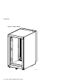
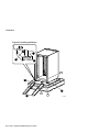
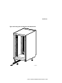
H9A11 Cabinet Installation/Owner's Guide Part Number: EK-H9A11-IN. B01 June 1999 Compaq Computer Corporation Houston, Texas June 1999 COMPAQ COMPUTER CORPORATION SHALL NOT BE LIABLE FOR TECHNICAL OR EDITORIAL ERRORS OR OMISSIONS CONTAINED HEREIN, NOR FOR INCIDENTAL OR CONSEQUENTIAL DAMAGES RESULTING FROM THE FURNISHING, PERFORMANCE, OR USE OF THIS MATERIAL. THIS INFORMATION IS PROVIDED “AS IS” AND COMPAQ COMPUTER CORPORATION DISCLAIMS ANY WARRANTIES, EXPRESS, IMPLIED OR STATUTORY AND EXPRESSLY DISCLAIMS THE IMPLIED WARRANTIES OF MERCHANTABILITY, FITNESS FOR PARTICULAR PURPOSE, GOOD TITLE AND AGAINST INFRINGEMENT. This publication contains information protected by copyright. No part of this publication may be photocopied or reproduced in any form without prior written consent from Compaq Computer Corporation. 1999 Compaq Computer Corporation. All rights reserved. The software described in this guide is furnished under a license agreement or nondisclosure agreement. The software may be used or copied only in accordance with the terms of the agreement. Compaq and the Compaq logo are registered in United States Patent and Trademark Office. Other product names mentioned herein may be trademarks and/or registered trademarks of their respective companies. Table of Contents Preface Overview .................................................................................................................................... v Intended Audience ...................................................................................................................... v How to Use This Guide ............................................................................................................... v Organization .............................................................................................................................. vi Conventions ...............................................................................................................................vi Safety Symbol............................................................................................................................ vi Reader's Comments...................................................................................................................vii 1 Introduction 1.1 Description........................................................................................................................ 1–1 1.2 Specifications .................................................................................................................... 1–3 2 Installation 2.1 Introduction....................................................................................................................... 2–1 2.2 Tools Required.................................................................................................................. 2–1 2.3 Site Planning ..................................................................................................................... 2–1 2.4 Unpacking......................................................................................................................... 2–3 2.5 Installation Procedures....................................................................................................... 2–9 2.5.1 Removing and Replacing the Rear Lift-Off Door.................................................... 2–10 2.5.2 Removing and Replacing the Front Filler Panels..................................................... 2–12 2.5.3 Pulling Out and Adjusting the Stabilizer Bar .......................................................... 2–14 2.5.4 Removing and Replacing the Power Distribution Unit ............................................ 2–16 A Field Replaceable Units (FRUs) iii Figures Figure 1-1 H9A11 Cabinet ...................................................................................................... 1–2 Figure 2-1 Unpacking the Cabinet ........................................................................................... 2–4 Figure 2-2 Installing the Ramps............................................................................................... 2–6 Figure 2-3 Deskidding the Cabinet .......................................................................................... 2–8 Figure 2-4 Removing and Replacing the Rear Lift-Off Door .................................................. 2–11 Figure 2-5 Removing and Replacing the Front Filler Panels................................................... 2–13 Figure 2-6 Pulling Out and Adjusting the Stabilizer Bar......................................................... 2–15 Figure 2-7 Removing and Replacing the Power Distribution Unit .......................................... 2–17 Tables Table A-1 Field Replaceable Units (FRUs)..............................................................................A–1 iv Preface Overview This guide provides the information necessary to install the H9A11 Cabinet. This guide does not provide information concerning systems that can be installed in the cabinet. For information concerning systems installed in the cabinet, refer to the respective documentation shipped with the system. Intended Audience The instructions in this guide are for Compaq Customer Service representatives and customer maintenance personnel who are familiar with computer hardware and operating systems. Personnel should be experienced and trained in installing computer and related equipment. How to Use This Guide Read all of this guide before installing the H9A11 Cabinet. As mentioned earlier, for information concerning systems installed in the cabinet, refer to the respective documentation shipped with the system. Before installation, review the warranty. The terms of the warranty agreement with Compaq may require that a qualified Compaq Customer Service representative install the system. Contact your local Compaq representative if you have any questions. v Organization This guide is organized as follows: Chapter 1, Introduction -- Provides an overview of the H9A11 Cabinet features and specifications. Chapter 2, Installation -- Provides site preparation, unpacking, and installation information. Appendix A, Field Replaceable Units (FRUs) -- Provides a list of the field replaceable units (FRUs) for the H9A11 Cabinet. Conventions The following conventions are used in this guide: Convention Meaning Note A note calls the reader's attention to important information. Caution Cautions provide information to prevent damage to equipment or software. Read these carefully. WARNING A warning contains information essential to the safety of personnel. Safety Symbol The following symbol appears on the power distribution unit. Please review its definition below: This Dangerous Voltage warning symbol indicates a risk of electric shock and indicates hazards from dangerous voltage. vi Reader's Comments Compaq welcomes your comments on this or any other manual. You can send your comments to Compaq in the following ways: • Internet electronic mail: [email protected] • Mail: Compaq Computer Corporation Information Design PKO3-2/21J 129 Parker Street Maynard, MA 01754-2199 For additional information, call 1-800-282-6672. vii This is some white text. 1 Introduction 1.1 Description The H9A11 Cabinet (Figure 1-1) is a low-cost, computer-equipment enclosure system that meets the Electronic Industries Association (EIA) standard 310C and the International Electrotechnical Commission (IEC) 297 standards and can accommodate fixed or slidemounted chassis that fit into a standard 48.26-cm (19-in.) rack. The cabinet has the following factory installed features: • Equipment mounting rails with the EIA universal rail-hole pattern • Front trim kit that provides a finished look to the front opening of the cabinet • Vented rear lift-off door • Nonvented top cover • Four nonlocking casters that facilitate the placement of the cabinet. The front two casters swivel. The rear two casters are fixed. • Adjustable leveling feet that are used to stabilize and secure the cabinet at the installation site. • Stabilizer bar that is used to provide cabinet stability when installing or sliding equipment out of the cabinet. • A single-phase H7600-AA (120 Vac), H7600-AB (240 Vac), or H7600-DB (240 Vac) power distribution units (PDU) --- Each H7600-AA/AB power distribution unit provides ten (10) ac power outlets and each H7600-DB power distribution unit provides twelve (12) ac power outlets. H9A11 Cabinet Installation/Owner’s Guide 1–1 Introduction Figure 1-1 H9A11 Cabinet scale=.12 scale=.9 Not for external loads J1 LJ-04803 1–2 H9A11 Cabinet Installation/Owner’s Guide Introduction 1.2 Specifications Specifications for the H9A11 Cabinet are as follows: Physical Height, overall 110.0 cm (43.31 in.) Width, overall 60.0 cm (23.60 in.) Depth, overall 86.0 cm (33.86 in.) Maximum vertical rackmounting space 93.35 cm (36.75 in.) Maximum vertical rackmounting space (with power distribution unit installed)\ 88.9 cm (35.00 in.) Horizontal rack width Standard 48.26-cm (19-in.) Weight - Cabinet with power distribution unit 80.74 kg (178 lb) - Cabinet with power distribution unit plus packing material 103.42 kg (228 lb) - Fully configured (filled) cabinet Up to 420.94 kg (928 lb) - Fully configured (filled) cabinet plus packing material Up to 443.62 kg (978 lb) Casters, swivel, nonlocking: Diameter: Maximum capacity: 7.62 cm (3 in.) 225 kg (500 lb) Casters, fixed, nonlocking: Diameter: Maximum capacity: 7.62 cm (3 in.) 225 kg (500 lb) Enclosure finish Painted Electrical AC input voltage for H7600-AA PDU 100 to 120 Vac, single-phase, 3-wire AC input voltage for H7600-AB PDU 220 to 240 Vac, single-phase, 3-wire AC input voltage for H7600-DB PDU 200 to 240 Vac, single-phase, 3-wire AC load 24 A per H7600-AA PDU 16 A per H7600-AB/DB PDU Input line frequency range 47 to 63 Hz Input power at full load 2.88 kVA per H7600-AA PDU 3.84 kVA per H7600-AB/DB PDU 1–3 H9A11 Cabinet Installation/Owner’s Guide Introduction Power cord (attached) 1–4 H9A11 Cabinet Installation/Owner’s Guide H7600-AA - 120 Vac with L5-30P connector H7600-AB - 240 Vac with L6-20P connector H7600-DB - 240 Vac with IEC 309 connector 2 Installation 2.1 Introduction This chapter provides the following information: • Tools Required (Section 2.2) • Site Planning (Section 2.3) • Unpacking (Section 2.4) • Installation Procedures (Section 2.5) 2.2 Tools Required The tools needed to install the H9A11 Cabinet are: • Utility knife • Phillips screwdriver • 5/8-inch box wrench or adjustable wrench 2.3 Site Planning The cabinet requires a space of 60.0 cm (23.60 in.) by 86.0 cm (33.86 in.). In addition, the cabinet requires a clearance of 91.44 cm (36.00 in.) at both the front and rear of the cabinet for service. This may be greater depending on the distance that a system may be slid out of the cabinet. H9A11 Cabinet Installation/Owner's Guide 2–1 Installation _______________________ WARNING __________________________ High Leakage Current --- An insulated earthing conductor that is identical in size, insulation material, and thickness to the earthed and unearthed branchcircuit supply conductors (except that it is green with or without one or more yellow stripes) is to be installed as part of the branch circuit that supplies the unit or system. The earthing conductor described is to be connected to earth at the service equipment or, if supplied by a separately derived system, at the supply transformer or motor-generator set. The attachment-plug receptacles in the vicinity of the unit or system are all to be of an earthing type, and the earthing conductors serving these receptacles are to be connected to earth at the service equipment. ___________________________________________________________ _______________________ WARNING __________________________ Use sufficient personnel when unloading the cabinet from the pallet or moving the cabinet to a new location. The cabinet weighs 80.74 kg (178 lb) empty, and can weigh up to 420.94 kg (928 lb) fully configured. ___________________________________________________________ For site preparation details concerning the system devices installed or the systems to be installed in the cabinet, refer to the documentation for those systems. 2–2 H9A11 Cabinet Installation/Owner's Guide Installation 2.4 Unpacking The cabinet is shipped on a wooden pallet. Proceed as follows to unpack the cabinet: 1. 2. 3. Position the pallet with the cabinet in an area that provides sufficient workspace for unpacking. Ensure that there is sufficient clearance in front of the pallet (marked with a large F) to roll the cabinet down the ramps. Refer to Figure 2-1. Cut and remove the plastic wrapping that secures the corner posts and the carton to the cabinet. The carton contains the two ramps. Remove the corner posts and the carton from the pallet . _________________________ Caution ___________________________ In the next step, take care not to damage the cabinet finish when removing the shrinkwrap. ____________________________________________________________ 4. 5. Remove the plastic bag covering the cabinet. Check the cabinet and the associated equipment for any external damage. Report any damage to Compaq Customer Service or a Compaq sales office and to the responsible freight carrier. __________________________ Note _____________________________ Keep all packing material and receipts in case a damage claim is filed. ____________________________________________________________ H9A11 Cabinet Installation/Owner's Guide 2–3 Installation Figure 2-1 Unpacking the Cabinet Not for external loads 1 J1 F 2 2 Not for external loads scale=.12 3 J1 F 4 2 5 2–4 H9A11 Cabinet Installation/Owner's Guide LJ-04804 Installation 6. Refer to Figure 2-2. Remove the four shipping bolts and brackets that secure the four cabinet leveler feet to the pallet . __________________________ Note _____________________________ The ramps attach to the front of the pallet. Therefore, the cabinet will have to be rolled frontwards down the ramps. ____________________________________________________________ 7. Remove the ramps ¡ from the shipping carton and set the ramps in the holes ¢ provided at the front of the pallet . Ensure that the arrows on the ramps match the pallet arrows as shown in Figure 2-2. _________________________ Caution ___________________________ In the next step, the leveler feet must be fully retracted to prevent contact with the ramp or the floor when the cabinet is unloaded from the pallet. ____________________________________________________________ 8. Adjust the four cabinet leveler feet and the leveler foot on the stabilizer bar to the maximum upward position. H9A11 Cabinet Installation/Owner's Guide 2–5 Installation Figure 2-2 Installing the Ramps 7 6 8 scale=.12 Not for external loads 3 J1 10 4 1 9 2 LJ-04805 2–6 H9A11 Cabinet Installation/Owner's Guide Installation ________________________WARNING __________________________ In the following step, use sufficient personnel to move the cabinet off the pallet. The cabinet weighs 80.74 kg (178 lb) empty, and can weigh up to 420.94 kg (928 lb) fully configured. If equipment is installed in the cabinet, the cabinet may become top heavy and could accelerate rapidly down the ramps if not restrained. Be prepared to guide and control the motion of the cabinet. ____________________________________________________________ 9. Refer to Figure 2-3 and roll the cabinet down the ramps using sufficient personnel for safety. 10. Wheel the cabinet to the desired location. 11. Adjust the leveler feet downward so that the cabinet is level and the load is removed from the casters. _________________________ Caution ___________________________ Ensure that the leveler feet extend enough to carry the load of the cabinet so that the casters spin freely. If not, damage to the casters will result over an extended period of time. ____________________________________________________________ H9A11 Cabinet Installation/Owner's Guide 2–7 Installation Figure 2-3 Deskidding the Cabinet Not for external loads scale=.12 J1 LJ-04806 2–8 H9A11 Cabinet Installation/Owner's Guide Installation 2.5 Installation Procedures During the installation of the cabinet, one or more of the following procedures may be needed: • Removing and Replacing the Rear Lift-Off Door (Section 2.5.1) • Removing and Replacing the Front Filler Panels (Section 2.5.2) • Pulling Out and Adjusting the Stabilizer Bar (Section 2.5.3) • Removing and Replacing the Power Distribution Unit (Section 2.5.4) H9A11 Cabinet Installation/Owner's Guide 2–9 Installation 2.5.1 Removing and Replacing the Rear Lift-Off Door The rear lift-off door provides access into the rear of the cabinet. To remove the rear lift-off door, refer to Figure 2-4 and proceed as follows: Removal 1. Remove the two Phillips-head screws that secure the rear lift-off door to the two brackets at the top rear of the cabinet. 2. Grasp both sides of the rear lift-off door about midway up the door. Then lift the door up until the securing tabs on the rear lift-off door come out of the tab catches on the cabinet. 3. Lift the door off and away from the cabinet. 4. Place the rear lift-off door aside and out of the way. Replacement To replace the rear lift-off door, reverse the removal procedure, steps 1 through 4. 2–10 H9A11 Cabinet Installation/Owner's Guide Installation Figure 2-4 Removing and Replacing the Rear Lift-Off Door 1 4 MAIN POWE R 2 3 LJ-04807 H9A11 Cabinet Installation/Owner's Guide 2–11 Installation 2.5.2 Removing and Replacing the Front Filler Pa nels To remove a front filler panel, refer to Figure 2-5 and proceed as follows: Removal Grasp the front filler panel on both sides and then pull straight back away from the cabinet. Replacement To replace a front filler panel , align the sockets on the front filler panel (refer to the exploded view) with the appropriate ball studs on the rails and push the panel into place. 2–12 H9A11 Cabinet Installation/Owner's Guide Installation Figure 2-5 Removing and Replacing the Front Filler Panels scale=.12 scale=.9 4 1 2 Not for external loads J1 3 4 3 2 1 LJ-04808 H9A11 Cabinet Installation/Owner's Guide 2–13 Installation 2.5.3 Pulling Out and Adjusting the Stabilizer Bar The stabilizer bar pulls straight out from the bottom front of the cabinet as shown in Figure 2-6. When the stabilizer bar is fully extended, adjust the foot at the end of the stabilizer bar until it touches the floor. _______________________ WARNING __________________________ The stabilizer bar must be fully extended before any system is extended out of the cabinet on its slides. ___________________________________________________________ The H9A11 Cabinet can hold various system configurations. The amount of force required to tip or make the cabinet unstable differs with each configuration. 2–14 H9A11 Cabinet Installation/Owner's Guide Installation Figure 2-6 Pulling Out and Adjusting the Stabilizer Bar Not for external loads Scale=.12 then .72 J1 2 1 3 LJ-04809 H9A11 Cabinet Installation/Owner's Guide 2–15 Installation 2.5.4 Removing and Replacing the Power Distribu tion Unit _______________________ WARNING __________________________ There can be one or more PDUs per cabinet. Ensure that all systems installed in the cabinet are turned off as described in the system documentation before performing the following procedure. ___________________________________________________________ To remove a power distribution unit, refer to Figure 2-7 and proceed as follows: Removal 1. If the cabinet contains an operating system, turn off the system as described in the system documentation. 2. Remove the two Phillips-head screws that secure the rear lift-off door to the two brackets at the top rear of the cabinet, and lift the door off of the cabinet (refer to Section 2.5.1). 3. Set the Main Power switch on all power distribution units to the off (O) position. 4. Disconnect the power distribution units from the ac power source. 5. Remove the bottom front filler panel (refer to Section 2.5.2). This provides access to the ac outlets on the power distribution units. 6. Note and record the power cord connections to the outlets at the rear of the failed power distribution unit. Then unplug the power cords from that power distribution unit. 7. At the rear of the cabinet, remove the four (4) 10-32 truss-head screws that secure the power distribution unit to the rear rails (via the four (4) 10-32 clip nuts . 8. Pull out the power distribution unit and remove it from the cabinet. Replacement To replace a power distribution unit, reverse the removal procedure, steps 2 through 8, then follow the power-on procedure in the system documentation. 2–16 H9A11 Cabinet Installation/Owner's Guide Installation Figure 2-7 Removing and Replacing the Power Distribution Unit 2 1 Not for external loads J1 J2 J3 M AI N PO W ER J4 Ne s’appliqu pas a l’alimentation externe. J5 4 4 MAI N POW ER 5 3 3 LJ-04810 H9A11 Cabinet Installation/Owner's Guide 2–17 This is some white text. A Field Replaceable Units (FRUs) Table A-1 lists the field replaceable units (FRUs) for the H9A11 cabinet. Table A-1 Field Replaceable Units (FRUs) Description Part Number Power distribution unit, 100 to 120 Vac H7600-AA Power distribution unit, 200 to 240 Vac H7600-AB Power distribution unit, 200 to 240 Vac H7600-DB H9A11 Cabinet Installation/Owner's Guide A–1 Help