1
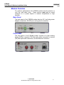
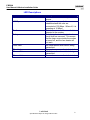
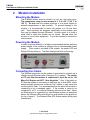
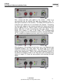
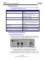
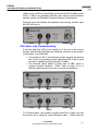
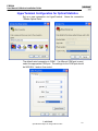
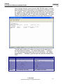
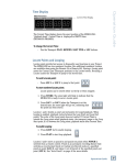
E BEAM
User Manual & Modem Installation Guide
. .
. . . digital
User Manual & Modem Installation Guide
July 2005
Draft Version 07012005
whirlwind
99 Ling Road
Rochester, NY 14612
Telephone: 888.733.4396
Fax: 585.865.8930
Email: [email protected]
Technical Support: [email protected]
E BEAM
User Manual & Modem Installation Guide
Table of Contents
1
USER MANUAL ................................................................................................................................. 3
INTRODUCTION .......................................................................................................................................... 3
Applications ......................................................................................................................................... 4
MODEM OVERVIEW .................................................................................................................................... 5
Back Panel .......................................................................................................................................... 5
Front Panel.......................................................................................................................................... 5
LED Descriptions............................................................................................................................................ 6
2
MODEM INSTALLATION................................................................................................................. 7
MOUNTING THE MODEM ............................................................................................................................ 7
POWERING THE MODEM ............................................................................................................................ 7
CONNECTING THE CABLES ........................................................................................................................ 7
LED DESCRIPTIONS .................................................................................................................................. 9
TROUBLESHOOTING BY LED STATUS ....................................................................................................... 9
Safety LED Troubleshooting............................................................................................................. 9
Fiber Optic Link Troubleshooting ................................................................................................... 10
HYPERTERMINAL CONFIGURATION FOR OPTICAL STATISTICS .............................................................. 12
UNDERSTANDING RECEIVED OPTICAL POWER LEVEL READINGS ......................................................... 14
Received Optical Power at the Modem......................................................................................... 14
TROUBLESHOOTING GUIDE ..................................................................................................................... 15
© whirlwind
Specifications subject to change without notice
2
E BEAM
User Manual & Modem Installation Guide
1
USER MANUAL
Introduction
Thank you for purchasing the latest in laser communications
technology! The Whirlwind E BEAM is a system for transporting
Ethernet or CobraNet™ data, either point-to-point or cascaded, over a
modulated Class One IR laser beam. It represents the latest
breakthrough technology in wireless digital laser transmission. The
100 Mbps Full-Duplex bandwidth has the capacity for transmitting and
receiving large amounts of data or 128 of channels of CobraNet audio
in real time at distances from 10m - 300m. Following soon will be a 1
Gbps version which will increase capacity ten-fold. Switching between
100 Mbps and 1 Gbps only requires changing the media converter, the
antenna supports both versions. The E BEAM can solve many of the
logistical problems encountered when using standard copper wire or
fiber optic cabling. It's a great solution for "on the spot" setup where
there is breaking news, at music festivals, over highways, building to
building, anywhere a laser beam can travel and cable cannot. You can
route the beam vertically up building cores or horizontally below a
ceiling. Link up offices, campuses, stages, and sporting events without
trenching cable or installing conduit. Additional product features
include:
!
!
!
!
!
!
Easy installation
RS-232 interface (used for factory programming)
No electric utility connection to the roof required
No FCC license required
Cold weather protection
Easy upgrade
© whirlwind
Specifications subject to change without notice
3
E BEAM
User Manual & Modem Installation Guide
Applications
E BEAM products provide the following applications:
!
!
!
!
!
!
!
!
!
!
!
!
Concert Stages
Sporting Events
Fiber Extension
Local Area Network (LAN) Extension
Campus Connectivity
Voice over IP (VoIP)
T1/E1 & Private Branch Exchange (PBX) Extension
2G + 3G Base Station Interconnect
Radio Frequency (RF) & Microwave Alternative
RF & Microwave Backup
Fiber Backup
Disaster Recovery
© whirlwind
Specifications subject to change without notice
4
E BEAM
User Manual & Modem Installation Guide
Modem Overview
For optimum performance, the E BEAM modem must be stored in a
cool, dry, and clean room. These devices must not be stored
outdoors or in a place subject to extreme temperatures or high
humidity.
Back Panel
The back panel of the E BEAM modem has two 48 V wall plug power
adapter connections, RS-232 port, and a ground connection.
Front Panel
The front panel of the E BEAM modem consists of 8 light emitting
diodes (LEDs), a transmit (TX) fiber optic cable connection, a receive
(RX) fiber optic cable connection, and an Ethernet connection.
© whirlwind
Specifications subject to change without notice
5
E BEAM
User Manual & Modem Installation Guide
LED Descriptions
LED
Power
100Mbps
Fault
Safety
Fiber Data
Fiber Link
Ethernet Data
Ethernet Link
Description
Green when connected to a power
source.
Amber when a proper link is
established and the units are
connected at 100 Mbps. When off, it is
operating at 10 Mbps.
Red when an internal firmware fault is
detected in the modem.
Red when a heater/safety interlock
circuit fault has occurred. This means
that the laser source inside the modem
is turned off, and the lens heater will
not work.
Will flicker amber when data is being
transmitted.
Green when a connection is detected.
Will flicker amber when data is being
transmitted.
Green when a connection is detected.
© whirlwind
Specifications subject to change without notice
6
E BEAM
User Manual & Modem Installation Guide
2
Modem Installation
Mounting the Modem
The E BEAM modem must be stored in a cool, dry, and clean room.
The temperature range for the modem is 0˚ C to +50˚ C (32˚ F to
122˚ F). Do not store the modem outdoors or in a place subject to
extreme temperatures or high humidity. To prevent damage to the
modem, it is recommended to mount the modem in a 19 inch telco
rack. These products are designed specifically for the modem, and
they can be ordered through Whirlwind. Another option is to build a
small shelf in which the modem can be stored. Do not place the
modem on top of other equipment. It must be mounted or secured in
some manner.
Powering the Modem
In order to ensure reliability, it is highly recommended that the wall plug
power adapter of the modem be plugged into an uninterruptible power
supply.
After power is provided to the modem, the power LED and
Safety LED should be on. The fiber data light will also be flickering.
Connecting the Cables
The Ethernet connection on the modem is connected to a switch via a
straight through Ethernet cable (Category 5E or greater). The switch
or PC port that the modem is connected to must be set to 100
Mbps Full Duplex and NOT “Auto Negotiate.” Also, if the switch or
PC that the modem is connecting to has been set to Auto-MDX, which
detects straight through and crossover Cat 5 cables, it may cause the
modem lights to flash. It is recommended that the switch the modem is
connecting to be a managed switch. If the modem is going to be
connected to a PC, a crossover Ethernet cable must be used. When
the Ethernet port is connected to a valid Ethernet source, as described
above, the Ethernet LEDs should light up as illustrated in the graphic at
the top of page 8. The Ethernet Data LED flickers amber during data
transmission.
© whirlwind
Specifications subject to change without notice
7
E BEAM
User Manual & Modem Installation Guide
Next, connect the fiber optic cables to the modem. (*Note: It is
recommended that the lettered fiber cable be connected to the “TX”
fiber optic connection on the modem.) The Safety LED should turn on
if the fiber optic cables are not connected to the antenna. Connecting
the fiber optic cables to the antenna activates the lasers and should
turn the Safety LED off. Expect a delay of a few seconds before the
Safety LED turns off after connecting the fiber optic cables. If the
Safety LED remains lit, refer to the Safety LED Troubleshooting
section on page 9 for more information on how to turn the Safety LED
off. To complete the alignment process, refer to the Installation Guide.
After plugging in the modems at both sites, and if the alignment was
completed properly, the Fiber Optic Link should light up at both
locations as shown in the graphic below. The Data LEDs flicker yellow
during data transmission. Refer to the Antenna Alignment section of
the Antenna Installation Guide or the Fiber Optic Link Troubleshooting
section on page 10 if there are any problems with attaining the laser
signal.
© whirlwind
Specifications subject to change without notice
8
E BEAM
User Manual & Modem Installation Guide
LED Descriptions
As was previously discussed, the front panel of the modem is equipped
with eight light-emitting diodes (LEDs).
LED
Description
Power
Green when connected to a power
source.
100Mbps
Amber when a proper link is
established and the units are
connected at 100 Mbps. When off, it is
operating at 10 Mbps.
Fault
Red when an internal firmware fault is
detected in the modem.
Safety
Red when a heater/safety interlock
circuit fault has occurred. This means
that the laser source inside the modem
is turned off, and the lens heater will
not work.
Fiber Data
Will flicker amber when data is being
transmitted.
Fiber Link
Green when a connection is detected.
Ethernet Data
Will flicker amber when data is being
transmitted.
Ethernet Link
Green when a connection is detected.
Troubleshooting by LED Status
Safety LED Troubleshooting
The graphic below illustrates the heater/safety interlock circuit fault.
The red Safety LED is on, which indicates that the fibers are not
connected properly to the antenna and/or the modem.
In order to turn the Safety LED off, the following must be checked:
!
!
Verify that the fibers are connected properly to the antenna
Verify that the fibers are connected properly to the modem
If the aforementioned is verified, and the Safety LED is still on, it may
be caused by damage to the fiber optic cables. Test the fiber optic
© whirlwind
Specifications subject to change without notice
9
E BEAM
User Manual & Modem Installation Guide
cables using an 850 nm optical light source and an 850 nm/dBm power
meter. If there is no damage to the fiber optic cables, and the problem
persists, please call Whirlwind Technical Support for assistance.
Once the laser link between the antennas is functioning, the fiber optic
link LED will turn on.
Fiber Optic Link Troubleshooting
If the fiber optic link LED on one modem is lit, but not on the remote
modem, and the fiber data lights are flickering, as shown in the graphic
on the below, it could be that:
!
!
The modem at Site 1 is transmitting a laser signal to the remote
site, but it is not receiving a laser signal from Site 2 that is good
enough to establish link (greater than -30 dBm).
The received optical power is higher than +2 dBm, which is
causing receiver saturation. (*Note: Refer to page 15 for a
definition and instructions on how to correct this problem.)
Site 1
Site 2
To fix this problem, one possible solution would be to make sure that
the remote site is using the correct Ethernet cable. Confirm that the
© whirlwind
Specifications subject to change without notice
10
E BEAM
User Manual & Modem Installation Guide
modem is connected to a valid Ethernet source which is set to 100
Mbps Full-Duplex and not “Auto Negotiate”, and that the Ethernet Link
LED is on. Also, use an 850 nanometer (nm) fiber optic power meter
to verify that the received power is not greater than +2 dBm. Unplug
the “RX” fiber cable and plug it into a fiber optic power meter to
measure the dBm value. Refer to the Understanding Received Optical
Power section on page 14 for a table that defines what power levels to
expect at certain distances.
If the problem persists, proceed to the location in which the modem
does not have fiber link (Site 1 in this example). Take an infrared
viewer up to the roof (or pertinent antenna location) of Site 1 and verify
that there is a laser source coming from Site 2. Through the infrared
viewer, the laser should appear as a bright circle. If the beam is not in
the field of view of the antenna at Site 1, walk around the antenna at
Site 1 with the viewer to see if the alignment from Site 2 to Site 1 is off.
Call Whirlwind Technical Support (Toll: 888-733-4396) if the problems
cannot be remedied.
© whirlwind
Specifications subject to change without notice
11
E BEAM
User Manual & Modem Installation Guide
HyperTerminal Configuration for Optical Statistics
Set up a new connection via HyperTerminal. Name the connection
“EBeam Optical Data”.
The default serial connection is COM1. If a different COM port is used,
select the appropriate COM port. The settings for the COM port should
be 9600-8-N-1 and no flow control.
© whirlwind
Specifications subject to change without notice
12
E BEAM
User Manual & Modem Installation Guide
Use a straight through, male-to-female, dB9, RS-232 cable to connect
from the back panel of the modem to the designated COM port on the
PC or laptop. Once HyperTerminal screen has been set up properly,
the screen is ready, and the cable has been connected, press and hold
the Shift and question mark (?) key down simultaneously. The stats
shown in the window below will appear on the HyperTerminal screen.
The table below defines the values and ranges for the stats shown in
the HyperTerminal interface. The values shown below “*** Settings
<?>” are what the components were set to at the factory. The values
shown below “*** Readings” gives the end user real-time values of the
stats.
Name
Bias
Temp
Tx Power
Rx Power
Safety
TP
FO
Errors
Description
Laser Bias Current
Laser Driver Temperature
Laser Transmit Power
Received Optical Power
Safety LED Status
Twisted Pair Status
Fiber Link Status
*For Factory Use Only
Range
≤ 500 mA
≤ 125û C
70 mW (+/- 30 mW)
Refer to page 14.
Ok/Fault
Lnk/Off
Lnk/Off
*For Factory Use Only
© whirlwind
Specifications subject to change without notice
13
E BEAM
User Manual & Modem Installation Guide
Understanding Received Optical Power Level
Readings
Depending on where in the system the received optical power level is
being measured and the distance between the antennas, the readings
will differ slightly. The two sections below define the power level
ranges for readings at the modem and the readings obtained by the
modem utility.
Received Optical Power at the Modem
The table below displays the nominal received optical power levels at
certain distances. The actual operating range of the 100 Mbps
system is +2 to -30 dBm.
Distance (m)
10 – 300
Power Level (dBm)
+2 to -12
Calculation: (# of feet * 0.3048 = # of meters)
Due to the fiber connectors and the fiber itself, there could be a loss of
up to 1 dBm in the actual reading.
* If there are problems with data transmission, and the modem seems
to be operating properly, the received optical power may be either out
of the operating range or too close to the maximum and minimum
received power thresholds. If the received power is greater than +2
dBm, it causes receiver saturation. To determine what the received
power level is, use an 850 nm fiber optic power meter to measure the
dBm value. If the received power is greater than +2 dBm, a
temporary solution is to simply disconnect the fibers connected to the
“RX” ports on the modem and connect the fiber to the power meter.
For tips about how to correct these types of problems, please refer to
the Troubleshooting Guide on page 15. When troubleshooting optical
power issues, it is recommended to use the optical power meter
instead of relying on the data provided by the software.
© whirlwind
Specifications subject to change without notice
14
E BEAM
User Manual & Modem Installation Guide
Troubleshooting Guide
If the link is inoperable, check the modem LEDs for the following:
1. Check power on LED
a. Power LED off
i. Power interruption
1. Unplugged power supply
2. Unplugged, turned off, or bad power strip/UPS
3. Thrown electric breaker
ii. Defective modem
b. Safety Shutoff/Interlock LED on
i. Safety Shutoff/Interlock interruption
1. Fiber unplugged from modem
2. Fiber unplugged from antenna
3. Fiber damage (e.g. cut)
ii. Defective modem
2. Check fiber optic link LED
a. Optic link LED off
i. Light signal interruption
1. Poor alignment on either side
2. Mount movement on either side
3. Line-of-sight obstruction on either side
ii. Fiber disconnected or broken on either side
iii. Remote site power interruption
iv. Defective modem
3. Check Ethernet link and data LEDs
a. Ethernet link LED off
i. Wire signal interruption
1. Ethernet cable unplugged from either side
2. Plugged into wrong, inactive, improperly configured, bad
switch port, or bad PC Network Interface Card
3. Bad Ethernet cable
4. Rebooted PC or switch
5. Defective modem
b. Ethernet data light inactive
i. Data transmission interruption
1. Plugged into wrong, inactive, improperly configured, bad
switch port, or bad PC Network Interface Card
2. Rebooted PC or switch
3. Improper or changed network configurations
4. Too much optical signal strength (receiver saturation)*
5. Defective modem
© whirlwind
Specifications subject to change without notice
15
E BEAM
User Manual & Modem Installation Guide
* Although all of the LEDs may be working properly, there can still be
errors in data transmission. When the signal strength is too high, it can
cause the unit to malfunction during data transmission. Too much
signal strength causes receiver saturation. A temporary solution for
this problem is to slightly pull out the ST connectors approximately
1mm on the modem. Tape the connectors so that they do not fall out,
until a fiber attenuation kit is purchased and installed.
Technical Support:
[email protected]
www.whirlwindusa.com
(888) 733-4396 Toll Free
(585) 663-8820 TEL
(585) 865-8939 FAX
© whirlwind
Specifications subject to change without notice
16