1
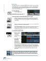
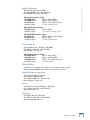
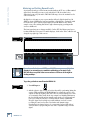
HDR 24/96
Metering and Setting Record Levels
A professional analog recorder has meters that indicate 0 VU at a +4 dBu nominal
signal level. Generally you can record peaks 10 to 15 dB above that before
distortion becomes objectionable. This 10-15 dB range above the nominal level is
called “headroom.”
On digital recorder meters, zero represents the full-scale digital signal level, 0
dBFS for short. 0 dBFS is the hottest signal that a digital device can handle, with
no headroom to spare. When a digital signal reaches 0 dBFS for more than a
sample or two, the resulting distortion is uglier than scraping your fingernails
across a chalkboard.
The front panel meters are always available. In the GUI, the Meters panel space
is shared with the Tools panel. To switch displays, click on the Tools or Meters tab
along the top right edge of the screen.
24TRACK /24BIT DIGITAL AUDIO HARD DISK RECORDER/EDITOR
1
OL
OL
OL
OL
OL
OL
OL
OL
OL
OL
OL
OL
OL
OL
OL
OL
OL
OL
OL
OL
OL
OL
2
4
2
4
2
4
2
4
2
4
2
4
2
4
2
4
2
4
2
4
2
4
2
4
2
4
2
4
2
4
2
4
2
4
2
4
2
4
2
4
2
4
2
4
7
7
7
7
7
7
7
7
7
7
7
7
7
7
7
7
7
7
7
7
7
7
7
10
15
10
15
10
15
10
15
10
15
10
15
10
15
10
15
10
15
10
15
10
15
10
15
10
15
10
15
10
15
10
15
10
15
10
15
10
15
10
15
10
15
10
15
10
15
20
25
20
25
20
25
20
25
20
25
20
25
20
25
20
25
20
25
20
25
20
25
20
25
20
25
20
25
20
25
20
25
20
25
20
25
20
25
20
25
20
25
20
25
20
25
30
35
40
30
35
40
30
35
40
30
35
40
30
35
40
30
35
40
30
35
40
30
35
40
30
35
40
30
35
40
30
35
40
30
35
40
30
35
40
30
35
40
30
35
40
30
35
40
30
35
40
30
35
40
30
35
40
30
35
40
30
35
40
30
35
40
30
35
40
50
50
50
50
50
50
50
50
50
50
50
50
50
50
50
50
50
50
50
50
50
50
50
2
3
4
5
6
7
8
9
10
11
12
13
14
15
16
17
18
19
20
21
22
OL
2
4
23
24
Remember, audio levels must NEVER reach 0 dBFS... never, ever, ever. Digital
clipping is an extremely nasty sound that could only pass for music if you
like what those crazy kids listen to over and over at all hours of the night including weekdays.
To get the get the best sound from the HDR24/96:
1. Turn All Input on.
ALL
INPUT
2. Ask the talent to play or sing as loud as they will be performing during the
session. While watching the HDR24/96 meters, adjust the console’s tape
outputs so that the signal peaks cause the red overload indicators to come
on occasionally. Then, back off the tape output level slightly. This insures
the best fidelity and the widest dynamic range in the recorded signal and
leaves you a little headroom to accommodate the talent’s enthusiasm.
Keep the signal levels as high as possible without overload, because
recording at lower levels reduces resolution and dynamic range.
Nonetheless it is always better to be conservative and avoid the risk of
overload than to try squeezing the last ounce of dynamic range from the
signal.
42
HDR 24/96
4. After adjusting the tape output levels for each console channel, follow
your console manufacturer’s instructions for setting the console tape
return levels.
The overload indicators on the HDR24/96 light when the signal level reaches
–1 dBFS. In the GUI, the white track number above the Meters flashes red
continuosly when the signal on that track clips (reaches 0 dBFS). If the tracks
Clip Indicator is lit, then turn down the console tape output to that track a bit.
Operation Guide
3. Alternately, if you have a tone generator or a sound source with a
constant volume (you can hold down a key on a synth), turn All Input on
and send the tone to all 24 tracks of the console. Adjust the output levels
to read 0 VU on analog consoles, or around –20 dBFS on digital consoles.
If the HDR24/96 meters read –15 to –20, you’re in good shape. This
leaves enough headroom for most popular music, but if you’re recording
acoustic music, jazz, classical, or narration, you may want to leave a little
more. When the talent starts to play you may have to make some final
tweaks to get everything just right.
To clear the Clip Indicator:
♦
Press Play.
♦
Click on the flashing track number, or click Play.
With analog I/O, a +22 dBu signal at the
dBu
HDR24/96 inputs and outputs corresponds to
equivalent
0 dBFS inside the HDR24/96. So, if your
+22 dBu
OL
2
+20
console has a nominal output level (0 VU) of
4
+18
7
+15
+4 dBu, there is 18 dB of headroom before
10
+12
you hit the maximum record level on the
15
+7
20
+2
HDR24/96. It also means that your console
25
–3
must be capable of putting out at least +22
30
–8
35
–13
dBu without distortion so the console doesn’t
40
–18
clip while the recorder is still within its
50
–28 dBu
working range. Most professional consoles
can output +22 dBu without breaking a
sweat (like the Mackie Analog and Digital
8•Bus consoles). But beware that semi-pro consoles often operate at a nominal
output level of –10dBV and will run out of steam before reaching a level that can
take advantage of the recorder’s full resolution.
Operation Guide
43
HDR 24/96
Recording
All recording in the HDR24/96 is non-destructive. When you record over existing
audio, the old audio is not “erased” as it with magnetic tape; rather, new audio
files are created in addition to the existing files.
Recording can only take place on tracks that are “armed” for recording.
To arm tracks for recording:
1. Press a track’s Record Ready button.
REC
2. Press it again to disarm the track.
1
1. Click a track’s Record Ready
button.
2. Click it again to disarm the track. Click and drag across several Record
Ready buttons to arm a range of tracks.
The Record Ready LED/button blinks when a track is armed and ready to record,
and glows when the track is recording.
To record:
1. Arm one or more tracks.
PLAY
RECORD
2. Press Play and Record simultaneously.
3. Press any Transport button other than Record to
stop recording.
1. Arm one or more tracks.
2. Click Record.
3. Click any transport button other than Record to stop recording.
The Record LED glows when the HDR24/96 is recording and blinks when Record
is engaged with no tracks armed (master record standby mode). Pressing
Play+Record together is a holdover from analog tape days to prevent you from
accidentally erasing the tape (and making the producer really, really upset) with
an inadvertent button press. But since recording with the HDR24/96 is always
non-destructive, there is never a danger of accidental erasure! So, to save wear
and tear on your fingers, the HDR24/96 offers the option of One Button Punch.
One Button Punch affects only front panel and Remote operation, but not the GUI.
To enable One Button Punch:
♦
44
HDR 24/96
Select One Button Punch from the Transport
pulldown menu. One Button Punch remains
enabled until you de-select it again from the
Transport menu.
♦
From Play, Press Record; there is no
need to hold Play to start recording.
Press any Transport button other than
Record to stop recording.
RECORD
When Record is engaged, you can punch in and out of record on individual tracks
using the Record Ready buttons. All of the recording methods sound the same,
with no clicks or gaps. Arming tracks before pressing Record is usually the best
way to work when tracking, while pressing Record with no tracks armed (Master
Record) and then punching with the Record Ready buttons is a handy way to
overdub individual tracks.
Operation Guide
To record with One Button Punch enabled:
Record Safe disarms all tracks and disables the Record Ready and master
Record buttons. Use Record Safe to prevent users from inadvertently recording
over existing audio.
To engage Record Safe:
♦
Press Rec Safe.
REC
SAFE
♦
Select Record Safe from
the Transport pulldown
menu.
Operation Guide
45
HDR 24/96
Auto Punch
Auto Punch allows you to automatically punch in and out between two predefined
points. This feature is very convenient when you need to nail a really tight punch
or need two hands to play your instrument. Numbered Locates 3 and 4 (available
on the GUI and the Remotes but not the front panel), double as the Auto Punch
Punch In and Punch Out points.
To enable Auto Punch:
Click the Punch button.
♦
When Punch is enabled, two red Punch
markers appear in the Marker Bar.
To adjust the Punch In and Punch Out markers (Locates 3 and 4):
♦
When the Transport is at the desired time, press CTRL (the cursor will
turn into a hand) and click inside the numbered Locate time display. Or,
when Punch is enabled, drag the Punch Marker in the Marker Bar to the
desired time.
or:
♦
Enter the desired time directly into the numbered Locate time display with
the mouse or keyboard (see Time Displays).
♦
Enable Punch Capture from the Transport Menu. Punch In and Punch Out
using any of the methods described under Recording. Punch Capture
automatically stores the latest Punch In point and Punch Out points to Loc
3 and Loc 4, respectively.
To perform Auto Punch recording:
1. Arm one or more
Tracks, and park
the transport
comfortably
before the Punch
In point.
2. Press Play and
Record. The
Record LED
blinks and the
HDR24/96 plays.
When Current
Time reaches the
Punch In point, the HDR24/96 begins recording on all armed tracks and
the Record LED glows. When Current Time reaches the Punch Out point,
the HDR24/96 stops recording, the Record LED blinks, and the HDR24/96
continues playing. The order of the Punch points does not matter; the
punch in always happens at the earlier point, and the punch out at the
later point.
Use Loop and Auto Punch together to do looped Auto Punch recording. In this
mode, your punch-in point must be no closer than 3 seconds to the loop start
point. The loop end point must be at least 3 seconds later than the punch-out
point.
46
HDR 24/96
Using a footswitch with the HDR24/96 gives you hands-free access to several of
the most-used HDR24/96 functions. The footswitch is extremely handy when you
want to use your hands for other tasks, like playing your instrument, working the
console, or eating pizza. Punching in and out is probably the most common use of
the footswitch, but it can do other tricks as well.
Punch punches-in just like pressing Play+Record and punches-out like
pressing Play. When playing, hitting the footswitch punches-in on all armed
tracks. When recording, hitting the footswitch again punches-out of Record,
but leaves the transport in Play.
Stop/Play acts just like the SPACEBAR on the keyboard. When the
Transport is stopped, it puts it into play; when moving, it stops the Transport.
Operation Guide
Footswitch Operation
Next Cue acts just like the + key on the numeric keypad and locates the
Transport to the next chronological Cue in the Project. When the Transport is
located on or after the last Cue, it locates back to the first Cue.
New Cue creates a new Cue. The Cue is automatically assigned the lowest
number available in the Cue List.
To assign the footswitch function:
1. Press the SYSTEM button. In the System menu, select Footswitch HDR.
Then select Punch, Stop/Play, Next Cue, or New Cue from the HDR
Footswitch mode menu.
2. Select OK, and press SYSTEM again to exit.
1. Select Setup from the Windows menu (or use keyboard shortcut CTRL+1)
and click on the General icon.
2. Select Punch, Stop/Play, Next Cue, or New Cue from the Footswitch
pulldown menu.
3. Click the arrow in the top right corner of the dialog or hit ESC to exit.
Footswitch
Operation Guide
47
HDR 24/96
Delete Last
With the HDR24/96 you don’t need to worry about filling up your hard disks with
unwanted takes. The Delete Last function erases all the audio files recorded
during the last record pass. A recording pass consists of all punches made within
one play/stop cycle.
To delete the last recording pass:
♦
Press the DELETE
LAST button. The LCD
display asks you to
confirm that you want
to delete the last
record pass. Press OK.
DELETE LAST
Also purge audio files
created during last
record pass?
Cancel No Yes
1. Click on the List View arrow to expand the
List View.
2. Click on the History tab (or use the keyboard
shortcut CTRL+6).
3. Scroll down to the bottom of the list and
search upwards for the last Record Pass entry.
4. Click on the entry just above it. The Undo
Record Pass dialog appears and asks you to
confirm the deletion.
5. Click Yes.
Alternate method:
1. Select Undo Record Pass from the
Edit menu immediately after
recording (or use the keyboard
shortcut CTRL+Z). The Undo
Record Pass dialog box appears and
asks you to confirm the deletion.
2. Click Yes.
Saving Projects
Every time you record new audio, the audio data and Project information is
automatically saved to disk. However, if you make other changes to the Project
(naming tracks, setting markers, editing, etc.) without recording new audio, you
must save the Project for these changes to be remembered. In other words, if you
quit without saving, no audio is lost, but your changes are. So once you start
editing, save often.
To save the current Project:
1. Press the PROJECT button.
2. From the Project Files menu
select Save.
3. Press the Project or Page
Left (<) button again to exit.
PROJECT MENU
New Open Save Delete
or:
♦
Select Save Project from the pulldown File menu.
or:
♦
48
HDR 24/96
->
PROJECT B
Use the CTRL+S keyboard shortcut.
With Mackie Media drives, you can back up your Projects on removable media
that you can hand to the client or store in your tape library. Backing up and
restoring Projects is as simple as copying the Projects between the internal and
the Mackie Media drives.
To copy Projects between the internal and Mackie Media drives:
1. Press the BACKUP
button.
T BACKUP D
BACKUP SOURCE: Internal
DESTINATION: External
Set
Source Dest Exit Backup
2. Using the - Dec / + Inc
or the << / >> buttons,
select Set Source to set the drive
the Project will be copied from, and Set Dest to set the drive the Project
will be copied to. Since a Project can’t be copied onto itself, the Source
and Destination drives must be different.
3. Select OK to return to the
Backup menu, then select
Backup. Choose the desired
Project using the (-) Dec / (+)
Inc or the << / >> buttons.
Operation Guide
Project Backup / Restore
Select Project to Backup
Eborall Song
<<
>> Cancel OK
4. Press OK. When the backup is completed, either select another Project to
back up or press the BACKUP button to exit.
1. Select Project Manager from the File menu, or use
the CTRL+B keyboard shortcut. The Project Manager
dialog box displays two columns listing all of the
Projects on each drive.
2. Click on the Project you want to copy. You can use
CTRL+click to select multiple Projects or
SHIFT+click to select a contiguous range of
Projects.
3. Click the Copy arrow or drag the selected Project(s)
across to the opposite column. Click the small arrow
in the top right corner of the dialog box or hit ESC to
exit.
Operation Guide
49
HDR 24/96
It is extremely important that you make backup copies of your projects at the end
of each session. While digital recording technology is highly reliable and hard disk
media is durable, sometimes stuff just happens. To reduce your risk of
catastrophic data loss (and the possible loss of $$ and clients), back up your
projects on two media before deleting them from your working drive(s).
There…. now you know better. So, don’t wait until disaster strikes to get backup
religion, and don’t complain to Mackie when your pet Rottweiler discovers that the
only copy of your client’s $20,000 project makes a superb chew toy and buries the
drive in the garden.
All media must be formatted before it can be used with the HDR24/96. Formatting
erases the media’s contents and prepares the file system for use with the HDR24/96.
You can either format media with the HDR24/96, or use existing FAT16 or FAT32formatted media. Mackie Media M•90 drives come pre-formatted and ready to use,
as do ORB disks for the Mackie Media PROJECT drive (be sure to buy IBM
formatted ORB disks). Most off-the-shelf UDMA IDE drives do not come preformatted.
Although you can use almost any IDE drive for backup, not all UDMA IDE drives
are fast enough to be used for recording and playback. If you want to use your own
UDMA IDE drive for recording and playback, you must format it with the HDR,
then verify that it is fast enough to record and playback at the maximum data rate
(24 track, 24-bit, 48 kHz). If the drive passes the performance verification test, it
is permanently “tagged” as a real-time drive. If it fails, then the drive can be used
for backup only. External drives that fail the record verification test appear with
an asterisk (*) in the GUI and front panel menus and dialogs.
To format and verify media performance from the HDR24/96:
1. Press the DISK UTIL button.
2. Now select Format. The LCD
screen displays a message
asking you to verify the drive
speed for recording and playback.
DISK UTILITY MENU
Mount
Format Verify
3. Select OK. When the format operation has completed, another message
appears asking you to verify the drive speed for recording and playback.
4. If a UDMA drive is installed, select OK. After the performance verification
is completed, select Continue. If a Mackie Media PROJECT drive is
installed, select Cancel; they are too slow to be used for recording and
playback.
5. Press DISK UTIL to exit.
50
HDR 24/96
Operation Guide
1. Select Format Drive from the File menu.
2. Click OK in the Format Drive conformation box.
4. When the format operation has completed,
another message will appear asking you to verify
the drive speed for recording and playback. If a
UDMA drive is installed, select OK. After the
performance verification is completed, select
Continue. If a Mackie Media PROJECT drive is
installed, select Cancel; they are too slow to be
used for recording and playback.
Some UDMA drives cannot keep up with the demand for 24 tracks of audio data.
So, before you rush to your local computer store and buy the cheapest UDMA
drive you can find, consider picking up some Mackie Media drives from your
nearest Mackie dealer instead (nudge nudge, say no more…).
There! You’re all boned up on the HDR24/96, so put down this booklet and get to
work ... or play. Thanks for reading this guide. If questions have gone
unanswered, check the Technical Reference Guide or Mackie’s website at
www.mackie.com. Enjoy!
Operation Guide
51
HDR 24/96
Appendix A: Compatible Cables
Analog and Digital Multitrack Cables
The following companies supply analog and digital multitrack cables for use with
the HDR24/96 I/O cards:
Horizon Music, Inc.
P.O. Box 1988, Cape Girardeau MO 63702-1988
Tel: (800) 255-9822; Fax: (800) 455-3460
http://www.horizonmusic.com
AIO•8 Analog Interface Cables
HDA8 Series
DB25 to [specify connector]
Connector options:
8 male XLR, 8 female XLR, or 8 1/4" TRS
Standard lengths:
5, 10, 15, 20, 25 feet
DIO•8 TDIF Interface Cables
TDIF Series
DB25 to DB25
Standard lengths:
5, 10, 15 feet
PDI•8 AES/EBU Interface Cables
HD44 Series
DB25 to [specify connector]
Connector options:
4 male + 4 female XLR, or DB25
Standard lengths:
5, 10, 15, 20, 25 feet
Hosa Technology, Inc.
6920 Hermosa Circle, Buena Park CA 90620
Tel: (714) 736-9270; Fax (714) 522-4540
http://www.hosatech.com
AIO•8 Analog Interface Cables
DTP Series
DB25 to 8 1/4" TRS
DTF Series
DB25 to 8 female XLR’s
DTM Series
DB25 to 8 male XLR’s
Standard lengths:
3, 4, 5, 7 meters
DIO•8 TDIF Interface Cables
DBK Series
DB25 to DB25
Standard lengths:
3, 15 feet
OPT•8 / DIO•8 ADAT Optical Interface Cables
OPT Series
Standard ADAT Optical cables
OPM Series
Jacketed ADAT Optical cables w/ metal headshell
OPT lengths:
2, 3, 6, 10, 13, 17, 30, 50 feet
OPM lengths:
3, 5, 10, 15, 20, 30, 50 feet
PDI•8 AES/EBU Interface Cables
DBK Series
DB25 to 4 male, 4 female XLR’s
Standard length:
8 meters only
52
HDR 24/96
Operation Guide
Marshall Electronics
PO Box 2027, Culver City, CA 90231
Tel: (800) 800-6608; Fax: (310) 391-8926
http://www.mars-cam.com/cable.html
AIO•8 Analog Interface Cables
DC-DAXM Series
DB25 to 8 male XLR’s
DC-DAXF Series
DB25 to 8 female XLR’s
DC-DAS Series
DB25 to 8 1/4" TRS connectors
Standard lengths:
3, 5, 10, 15, 20, 25 feet
DIO•8 TDIF Interface Cables
DCD-88D Series
DB25 to DB25.
Standard lengths:
1, 3, 6, 12, 15, 20, 25, 33 feet.
PDI•8 AES/EBU Interface Cables
DC-SYX Series
DB25 to 4 male, 4 female XLR’s
DC-DUB Series
DB25 to DB25
Standard lengths:
3, 5, 10, 15, 20, 25 feet
Pro Co Sound, Inc.
135 E. Kalamazoo Ave., Kalamazoo, MI 49007
Tel: (800) 253-7360; Fax: (616) 388-9681
http://www.procosound.com
AIO•8 Analog Interface Cables
DA-88 XM Series
DB25 to 8 male XLR’s
DA-88 XF Series
DB25 to 8 female XLR’s
DA-88 BQ Series
DB25 to 8 1/4" TRS connectors
Standard lengths:
5, 10, 15, 20 feet
Other Cables
In addition to the companies listed above, the following companies supply
individual 110Ω AES/EBU and/or 75Ω word clock and video cables:
Apogee Electronics Corporation
3145 Donald Douglas Loop South
Santa Monica, CA 90405-3210
Tel: (310) 915-1000; Fax: (310) 391-6262
http://www.apogeedigital.com
Canare
531 5th Street, Unit A, San Fernando, CA 91340
Tel: (818) 365-2446; Fax: (818) 365-0479
http://www.canare.com
Whirlwind
99 Ling Rd., Rochester, NY 14612
Tel: (888) 733-4396; Fax: (716) 865-8930
http://www.whirlwindusa.com
Operation Guide
53
Pin 14
Pin 15
Pin 16
Pin 17
Pin 18
Pin 19
Pin 20
Pin 21
Pin 22
Pin 23
Pin 24
Pin 25
Tape 17-24
Ch24
Ch24
Ch23
Ch22
Ch22
Ch21
Ch20
Ch20
Ch19
Ch18
Ch18
Ch17
Tape 9-16
Ch16
Ch16
Ch15
Ch14
Ch14
Ch13
Ch12
Ch12
Ch11
Ch10
Ch10
Ch 9
Tape 1-8
Ch 8
Ch 8
Ch 7
Ch 6
Ch 6
Ch 5
Ch 4
Ch 4
Ch 3
Ch 2
Ch 2
Ch 1
Signal
Description
Tape 17-24
+
shield
–
+
shield
–
+
shield
–
+
shield
–
N/C
Tape 9-16
Pin 1
Pin 2
Pin 3
Pin 4
Pin 5
Pin 6
Pin 7
Pin 8
Pin 9
Pin 10
Pin 11
Pin 12
Pin 13
Tape 1-8
AIO•8 Pinouts
Signal
Description
HDR 24/96
Appendix B: I/O Card Pinouts
–
+
shield
–
+
shield
–
+
shield
–
+
shield
Ch 8
Ch 7
Ch 7
Ch 6
Ch 5
Ch 5
Ch 4
Ch 3
Ch 3
Ch 2
Ch 1
Ch 1
Ch16
Ch15
Ch15
Ch14
Ch13
Ch13
Ch12
Ch11
Ch11
Ch10
Ch 9
Ch 9
Ch24
Ch23
Ch23
Ch22
Ch21
Ch21
Ch20
Ch19
Ch19
Ch18
Ch17
Ch17
PDI•8 Pinouts
Signal Description
Pin 1
Pin 2
Pin 3
Pin 4
Pin 5
Pin 6
Pin 7
Pin 8
Pin 9
Pin 10
Pin 11
Pin 12
Pin 13
Ch 1&2 In (+)
Ch 3&4 In (+)
Ch 5&6 In (+)
Ch 7&8 In (+)
Ch 1&2 Out (+)
Ch 3&4 Out (+)
Ch 5&6 Out (+)
Ch 7&8 Out (+)
N/C
Ground
N/C
Ground
Ground
Signal Description
Pin 14
Pin 15
Pin 16
Pin 17
Pin 18
Pin 19
Pin 20
Pin 21
Pin 22
Pin 23
Pin 24
Pin 25
Ch 1&2 In (–)
Ch 3&4 In (–)
Ch 5&6 In (–)
Ch 7&8 In (–)
Ch 1&2 Out (–)
Ch 3&4 Out (–)
Ch 5&6 Out (–)
Ch 7&8 Out (–)
Ground
N/C
Ground
Ground
+ = Hot or positive side of balanced signal
– = Cold or negative side of balanced signal
54
HDR 24/96
Although you probably won’t need them, troubleshooting tips can be found in the
Technical Reference Guide. Technical support is available by contacting your
Mackie dealer, calling Mackie Designs at (800) 258-6883 (8:00 AM to 5:00 PM
Pacific Time), or visiting Mackie’s website at www.mackie.com.
Please read the included warranty information, then complete and return the
included Warranty Registration card, or it’s straight to bed for you with no dinner.
Colophon
Operation Guide text composed by Dana Bourke, based on a ballet by Jeff Gilbert.
It was made possible by the teachings and donations of the HDR24/96 Design
Team, most notably Brian McCully and Bob Tudor. Graphics and layout were
performed by Tony “Waldog” Baird with technical support from Steve Eborall and
Frank “Weasel Boy” Heller. Cover art courtesy of Bryan Tiller. Long-winded
explanations, editing, and last minute updates from Mike Rivers, with
proofreading and final blessing by Jeff Gilbert. Proofreading and additional editing
by Linn Compton. Scott Garside was a pain the whole time.
Operation Guide
Troubleshooting and service
Demo Music Credits
Ode to Masters
Written by:
Published By:
Electric Guitar:
Classical Guitar:
Bass:
Drums:
Hammond B3:
Trumpet:
Jay Roberts and Rick Reid
Nigel Nose Music
Jay Roberts
Rick Reid
Dan Dean
Brendan Scanlan
Joey DeFrancesco
Joey DeFrancesco
Little Bit of Love
Written by:
Claude Gaudette & Alan Roy Scott BMI #877477
Published by:
KYUSHU BOY MUSIC BMI #231306319
Artist:
Shirley Meyers
Production Company:
Leggett Music Inc. Nashville Tn.
Produced by:
Keith Olsen
Arranged by:
Claude Gaudette and Keith Olsen
Keyboards:
Claude Gaudette, Richard Baker
Guitars:
Tim Pierce
Engineered by:
Keith Olsen and Peter Love
Recorded and Programmed at Goodnight LA Studios, Los Angeles
“Mackie,” the “Running Man” figure, “HDR24/96,” and “Digital 8•Bus” are
trademarks or registered trademarks of Mackie Designs Inc. All other brand
names mentioned are trademarks or registered trademarks of their respective
holders, and are hereby acknowledged.
© 2002 Mackie Designs Inc.
All Rights Reserved.
Printed in the U.S.A.
Operation Guide
55
16220 Wood-Red Rd. NE • Woodinville, WA 98072 • USA
US & Canada: 800/898-3211
Europe, Asia, Central & South America: 425/487-4333
Middle East & Africa: 31-20-654-4000
Fax: 425/487-4337 • www.mackie.com
E-mail: [email protected]