1
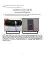
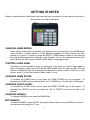
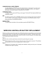
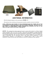
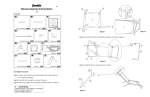
1
Table of Contents
CONTROLLER DEFINITIONS ........................................................................................................ 3
COMMUNICATION CABLES ........................................................................................................ 4
Connecting a Hard Wired Cable .............................................................................................. 4
GETTING STARTED ..................................................................................................................... 5
CHANGING GAME MODES: ..................................................................................................... 5
STARTING A NEW GAME: ........................................................................................................ 5
CHANGING HOME SCORE: ...................................................................................................... 5
CHANGING GUEST SCORE: ...................................................................................................... 5
CHANGING INNINGS: .............................................................................................................. 5
EDIT INNINGS:......................................................................................................................... 5
CHANGING BALLS AND STRIKES: ............................................................................................. 6
CHANGING OUTS: ................................................................................................................... 6
H/E:......................................................................................................................................... 6
NEW BATTER: ......................................................................................................................... 6
WIRELESS CONTROLLER BATTERY REPLACEMENT ...................................................................... 6
ADDITIONAL INFORMATION ...................................................................................................... 7
2
CONTROLLER DEFINITIONS
Before continuing, take a few moments and familiarize yourself with the following terms as they apply
to the controller. Some buttons on the keypad do not apply to all scoreboards. The buttons defined
below are used for scoring baseball and softball.
1. SET CLOCK:
The SET CLOCK button is used to set the time that will be displayed on a scoreboard with that capability. (This
button does not apply to scoreboards that do not have a clock feature.)
2. SELECT GAME:
The SELECT GAME button provides the method for re-assigning the proper sport for game play, in the event that
the scoreboard’s configuration is lost.
3. NEW GAME:
The NEW GAME button clears the scoreboard to display start-up values.
4. HOME SCORE:
The HOME SCORE button increases the HOME SCORE by one.
5. INNING:
The INNING button is used to advance to the next INNING.
6. GUEST SCORE:
The GUEST SCORE button increases the Guest Team score by one.
7. POWER Switch:
The POWER switch is used to turn the controller ON and OFF on wireless controllers ONLY. The switch does not
apply to cable operated controllers.
8. -1 HOME:
Use the -1 HOME button to decrease the HOME SCORE by one.
9. -1 GUEST:
Use the -1 GUEST button to decrease the GUEST SCORE by one.
10. OUT:
The OUT button increases the OUTs count by one.
11. H/E:
The H/E button is used to light the Hit / Error indicators on scoreboards with that feature. This button does not
apply if your scoreboard does not display HITS and ERRORS.
12. BALL:
The BALL button increases the BALLs count by one.
13. NEW BATTER:
The NEW BATTER button clears the BALLs and STRIKESs currently displayed on the scoreboard for a new
batter.
14. STRIKE:
3
The STRIKE button increases the STRIKEs count by one.
15. EDIT:
The EDIT button is used to edit the INNINGS count.
COMMUNICATION CABLES
Connecting a Hard Wired Cable
Using the supplied 20-ft. DIN cable, connect one end to either of the DIN sockets on back of
the controller and the other end to the junction box receptacle.
Cable – Back of Controller
Cable – Junction Box Receptacle
NOTE: When POWER is turned ON to the scoreboard, it will momentarily display the code for
the sport the scoreboard is ready to display in the HOME TEAM SCORE Section’s far right
digit, or, the one’s position. This code only shows for about three seconds and then changes
to the default 0 (zero) score. The code for baseball is “5”. In the event the scoreboard does
not display a “5” at start-up, follow the directions for changing GAME MODES in the
instructions below.
4
GETTING STARTED
Begin by making sure the Game Insert that came with your scoreboard is in the sleeve on the face of
the controller, as in the image below.
CHANGING GAME MODES:
When initially powering the scoreboard, pay attention to the far right digit of the HOME score
(ones position). It should display a 5 (this indicates baseball) for a few seconds and then
change to a 0 (zero). If it does not, press the SELECT GAME button for three (3) seconds and
then press the Inning button (button #5 on the keypad). To store the selection press the Out
button (button #9). Next, press the NEW GAME button to begin game-play.
STARTING A NEW GAME:
At power-up, the scoreboard is ready for game play. In the event you need to begin again or
start a new game, simply press and hold the NEW GAME button for three seconds. This will
clear the information from the scoreboard and display the start-up values of zero (0) in both
scores, a one (1) in the Period, and no balls, strikes, or outs.
CHANGING HOME SCORE:
To increase the HOME score by one, press the HOME SCORE key on the keypad. To
decrease the HOME score by one press the “red” -1 HOME key on the left side of the keypad.
CHANGING GUEST SCORE:
To increase the GUEST score by one, press the GUEST SCORE key on the keypad. To
decrease the GUEST score by one press the “red” -1 GUEST key on the left side of the
keypad.
CHANGING INNINGS:
To increase INNING by one press the INNING key.
EDIT INNINGS:
To edit the INNINGS, press the EDIT key quickly followed by the correct INNING key this will
only decrease the innings by (1) one.
5
CHANGING BALLS AND STRIKES:
To change BALLS or STRIKES, press the respective keys on the keypad. If you enter more
BALLS or STRIKES than you intended, simply press the respective keys on the keypad to
cycle back to the correct number of either BALLS or STRIKES.
CHANGING OUTS:
To change OUTS, press the OUT key on the keypad. The third OUT will clear the BALLS and
STRIKES to NONE.
H/E:
The H/E key lights the HIT and ERROR indicators on the scoreboard. The first press will light
the HIT indicator. A second press changes the lit indicator to the ERROR indicator. A third
press clears the HIT and ERROR indicators.
NEW BATTER:
To clear all balls and strikes for the next batter, press the NEW BATTER key.
WIRELESS CONTROLLER BATTERY REPLACEMENT
Wireless controllers receive their power from 4 AA batteries that are accessible by removing the back
cover on the controller. From time to time the batteries need to be replaced. The back cover is held
in place by tabs on the cover itself and is a snug fit so that no tools are required for the battery swap.
The following steps illustrate the process.
Step 1:
Turn the controller upside down and notice the pocket along the top edge.
Step 2:
While holding the controller, pull up on the back cover at the pocket to remove it. This will take
some pressure as the cover is designed with a “friction” type fit.
Step 3:
Replace the 4 AA batteries with 4 quality brand batteries, making sure they are in the proper
orientation with respect to polarity.
6
ADDITIONAL INFORMATION
After the last game simply turn the scoreboard’s POWER OFF.
After each use the controller and all accessories should be stored in a secure, dry location.
NOTE: AFTER EACH USE POWER TO THE SCOREBOARD MUST BE TURNED OFF AT THE
SCOREBOARD'S POWER DISCONNECT SWITCH OR CIRCUIT BREAKER. FAILURE TO DO SO
WILL RESULT IN UNNECESSARY POWER CONSUMPTION, SHORTEN THE LIFE OF THE
DISPLAYS AND OTHER ELECTRONIC COMPONENTS.
NOTICE: This equipment has been tested and found to comply with the limits for a Class A digital
device, pursuant to Part 15 of the FCC Rules. These limits are designed to provide reasonable
protection against harmful interference when the equipment is operated in a commercial environment.
This equipment generates, uses, and can radiate radio frequency energy and, if not installed and
used in accordance with the instruction manual, may cause harmful interference to radio
communications. Operation of this equipment in a residential area is likely to cause harmful
interference in which case the user will be required to correct the interference at their expense.
7