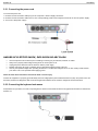
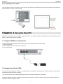
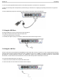
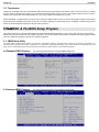
1
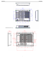
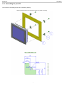
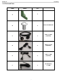
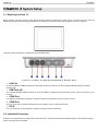
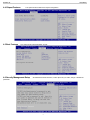
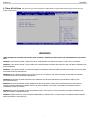
AcuPanel 12 User Manual AcuPanel 12 User Manual Version 7.1 Acura Embedded Systems Inc. AcuPanel 12 User Manual Copyright Copyright© 2011 All Rights Reserved - Printed in Acura Embedded Systems Inc Disclaimer Acura Embedded Systems Inc shall not be liable for technical or editorial errors or omissions contained herein; nor for incidental or consequential damages resulting from using this material, or the performance or use of this product. Acura Embedded Systems Inc reserves the right to change product specifications without notice. Information in this document may change without notice. No part of this document may be copied, reproduced, or transmitted by any means, for any purpose without prior written permission from Acura Embedded Systems Inc. Safety instructions 1. Please read these safety instructions carefully. 2. Please keep this User Manual for later reference. 3. Please disconnect this equipment from connecter before cleaning. Don’t use liquid or prayed detergent for cleaning. User moisture sheet or cloth for cleaning. 4. Make sure the equipment is connected to the power source with the correct voltage, frequency, and ampere. 5. All cautions and warnings on the equipment should be noted. 6. Never pour any liquid into opening: this could cause fire or electrical shock. 7. Never open the equipment. For safety reason, the equipment should only be opened by qualified service personnel. 8. If one of the following situations arises, get the equipment checked by a service personnel: A Liquid has penetrated into the equipment. B The equipment has been exposed to moisture. C The equipment has not worked well or you cannot get it work according to user manual. D The equipment has dropped and damaged. E If the equipment has obvious sign of breakage. The computer has been tested for conformance to international safety regulations. Like any electronic device, however, the computer should be used with care. To protect yourself from possible injury and to minimize the risk of damage to the computer, read and follow all the safety instructions mentioned in this manual. WARNING: Do not operate the computer with the cover removed. Power Cord Set Requirement The power cord set (appliance coupler, flexible cord) you received with the computer meets the requirements for use in the country where you purchased the equipment. Protect the power cord from being walked on or pinched particularly at plugs, convenience receptacles, and the point where they exit from apparatus. IMPORTANT:Loss of BIOS settings occurs when the battery is removed. BIOS settings must be reconfigured whenever the battery is replaced. WARNING:A risk of fire and chemical burn exists if the battery is not handled properly. Do not disassemble, crush, puncture, or short external contacts, or expose the battery to temperatures higher than 65 °C . Do not dispose of a used battery in water or fire. CAUTION:Danger of explosion if battery is incorrectly replaced. Replace only with same or equivalent type recommended by the manufacturer. Discard used batteries according to the manufacturer’s instructions. 1 AcuPanel 12 User Manual INDEX Table of Contents ........................................................................ 2 2.2. Installation Procedures ...........................................................9 2.2.1. Connecting the power cord ...................................................10 2.2.2. Connecting the keyboard and mouse ...................................10 2.2.3. Switching on the power .........................................................11 Chapter 1 General Information .................................................. 3 1.1. Introduction ............................................................................3 1.2. Features ..................................................................................3 1.3. Specification ...........................................................................3 1.3.1. Technical Specification ....................................................... 3 1.3.2. Display... ............................................................................. 3 1.3.3. Touch Screen ..................................................................... 4 1.3.4. I/O Interface ........................................................................ 4 1.3.5. Power .................................................................................. 4 1.3.6. Environment......................................................................... 4 1.3.7. Material ............................................................................... 4 1.3.8. Software .............................................................................. 4 1.3.9. Certifications ..................................................................... 5 Chapter 3 Using the Panel PC ..................................................... 11 3.1 Using the USB Mouse and Keyboard .........................................11 3.2 Using the Serial Ports (COM) .....................................................11 3.3 Using the USB Ports ...................................................................12 3.4 Using the LAN Port .....................................................................12 3.5 Touch screen ..............................................................................13 Chapter 4 The BIOS Setup Program ........................................... 13 Chapter 2 System Setup ............................................................ 9 4.1. CMOS Setup Utility ....................................................................13 4.2. Standard CMOS Features .........................................................13 4.3. Advanced BIOS Features ..........................................................13 4.4. Chipset Features........................................................................14 4.5. Boot Features ............................................................................14 4.6. Security Management Setup .....................................................14 4.7. Save & Exit Setup ......................................................................15 2.1. Exploring AcuPanel12 ...........................................................9 Warnings ...……..…………………….…...…………………………... 15 1.4. Physical Dimensions........................................................... 5 1.4.1. Assembling the panel PC .....................................................7 1.4.2. Enclosed Parts ......................................................................8 2 AcuPanel 12 User Manual Chapter 1 General Information 1.1. Introduction AcuPanel12 is an embedded Intel® Cedar Trail Dual Core 1.6 Ghz +Chipset: Intel® NM10 processor based Panel PC with a bright 10.4”/12.1" LCD display. The powerful Intel® NM10 chipsets bring the most dynamic applications to life without sacrifices to any industrial reliability. Delivering a variety of connectivity features, built-in USB and robust capacity of 2.5” SATA HDD, it is ideal for an all-around system performance. Furthermore, AcuPanel12 is equipped with fanless and no-ventilation-hole design, full IP67 featured with dustproof, waterproof, rugged aluminum enclosure and anti-collision function, the durable AcuPanel12 is suitable for any critical environment based on its Class1 and Division2 certificate . 1.2. Features The AcuPanel12 is a flexible, multi-functional flat panel PC. With following specifications that can be applied in diverse operational environments and implemented in various applications. • Rugged Aluminum Enclosure and Fanless Design • No ventilation Hole • Full IP67-Dustproof and Waterproof • Wide Temperature Operating Capability • Indoor/outdoor Environment • Stand/Cabinet/VESA (Optional) • Anti-vibration (MIL-STD-810G) • Anti-shock (MIL-STD-810G IEC 60068-2-27) System Design • Removable / Anti-vibration HDD Design • Board Wide Range DC to DC Power • Design Support 12V~24V Input 1.3. Specification The AcuPanel12 is a flexible, multi-functional flat panel PC. With following specifications that can be applied in diverse operational environments and implemented in multi-faceted applications. 1.3.1. Technical Specification • • • • • • • CPU: Embedded Intel® Cedar Trail Dual Core 1.6 Ghz +Chipset: Intel® NM10 Memory: 1 x 800 MHz SO-DIMM DDR3/DDR3L(1.35V) supports up to 4 GB Graphics Engine: Intel® GMA3600 with a 400 MHz Graphics Core BIOS: UEFI BIOS Storage: 1 x Internal 2.5" SATA HDD interface SSD, DOM, CF, Wide temperature HDD (Optional items) Watchdog Timer: Reset; 1 sec.~255 min. and 1 sec. or 1 min./step H/W Status Monitor: Monitoring system temperature, voltage, and cooling fan status. 1.3.2. Display • • • • Display Type:10.4”/ 12.1" Color TFT LCD or LED Support Dual Display Max Resolution: 800 x 600 pixels / 1024 x 768 pixels Brightness: 1000 cd/m² • • Touch Screen Type: Five-wire Analog Resistive Max Colors: 16,194,277 color 3 AcuPanel 12 • • User Manual Viewing Angle: 12.1" 80° (left), 80° (right), 80° (up), 80° (down) Lamp Life Time: 50,000 hours 1.3.3. Touch Screen • • • Touch Screen type: 5-wire Analog resistive type Light Transmission: 80% Durability (Touch lifetime): 35 million 1.3.4. I/O Interface • • • • • Serial Port: 2 x Serial port USB Port: 2 x USB 2.0 ports LAN Port: 1 x RJ45 Connector for 10/100/1000 Base T Ethernet Front LED: PWR / HDD Switch: Power button 1.3.5. Power • • • • • • Power Input Voltage: DC 12V Power Adapter: AC to DC 100-240VAC, DC12V / 3.42A, 65W (optional) Power consumption: 35W MAX Power management: APM / ACPI 2.0 Power Button: 1 x Power Button LED: Power / HDD LEDs 1.3.6. Environment • • • • • • • • • • Dimensions: 317 x 248 x 68 mm Temperature: Operating: -40°C ~ 65°C for SSD, DOM, CF, Wide temperature HDD; Operating: 0°C ~ 50°C for Normal HDD / Storage: -20°C ~ 70°C HDD/LCD wide temperature Humidity: 5% ~ 95% RH, (MIL STD 810G, Method 507.5 (Non-Operating) EMI/EMS: Meet the CE and FCC class B and VCCI regulation. Other function: Support USB device boot up (FDD,HDD,CD-ROM) IP: IP67 waterproof and dustproof (IEC 60529) RoHS: RoHS Compliant Vibration (MIL-STD-810G Method 514.6 Procedure I, Category 20, Fig 514.6C-1, Fig 514.6C-2, Fig 514.6C-3(Operating)). Shock (MIL-STD-810G Method 516.6) 1.3.7. Material • • • Front chassis material: Aluminum Front Bezel Rear chassis material Aluminum Enclosure Overlay material: PE Film 1.3.8. Software Software Support: Microsoft Windows7, XP Professional. 4 AcuPanel 12 User Manual 1.3.9. Certifications 1.4. Physical Dimensions Your panel PC is equipped with fanless and no-ventilation-hole design and is durable to suit any critical environment. The following drawing shows you detailed information for the dimensions. 5 AcuPanel 12 User Manual Dimensions (units in mm) 6 AcuPanel 12 User Manual 1.4.1. Assembling the panel PC The procedure for assembling the panel PC is identified by following drawing. Please follow the instruction below for panel mounting. 7 AcuPanel 12 User Manual 1.4.2. Enclosed Parts ITEM PARTS QTY SPEC 4 A M6*1.0+15PF-SUS B 4 C 1 RJ45, L=1.8M (Optional) D 2 DSUB, L=1.8M (Optional) E 2 USB, L=1.8M (Optional) F 1 DC Extension, L=1.8M 8 AcuPanel 12 User Manual Chapter 2 System Setup 2.1. Exploring AcuPanel 12 Before starting to set up the panel PC, take familiar with the locations and purposes of controls, drives, connectors and ports, which are illustrated in the figures below. When placed upright on the desktop, the front panel of the panel PC appears as shown in Figure 2.1. The bottom side of the panel PC is equipped the I/O as described below. 1. LAN Port 2. USB2.0 3. USB2.0 4. RS-232/422/485 5. RS-232 6. DC IN • LAN Port An internal 10Base-T/100Base-TX Ethernet LAN module connects your Panel PC to other computers/networks through a local area network (LAN). • USB Ports (x2) The Universal Serial Bus (USB) port allows you to connect USB 2.0-compliant devices (for example, printers, scanners and so on) to your Panel PC. • COM1 Port Your Panel PC is fitted with a COM port to enable connection of a serial device such as a modem or mouse. • COM2 Port Lets you connect a 9-pin external serial device such as a modem, mouse, or other serial devices. • DC IN Lets you connect the AC power adapter in supplying continuous power to AcuPanel12. 2.2. Installation Procedures AcuPanel 12 is designed and pre-configured for easy setup and use. This section describes the installation steps you should follow to get the system running as quickly as possible. 9 AcuPanel 12 User Manual 2.2.1. Connecting the power cord To connect the power cord: 1. Connect the DC extension cable plug to the computer’s Power Supply Connector. 2. Connect the DC extension cable wires to the corresponding positive and negative terminals on the DC power supply. 3. Turn on the DC power supply. HAZARD OF ELECTRIC SHOCK, EXPLOSION OR ARC FLASH • • • • • Remove all power from the device prior to installing or removing any accessories, hardware, or cables. Always use a properly rated voltage sensing device to confirm power is off. Unplug the power cable from both the Panel PC and the power supply. Replace and secure all covers or elements of the system before applying power to the unit. Use only the specified voltage when operating the Panel PC. The DC unit is designed to use 12 VDC. Always check whether your device is AC or DC powered before applying power. Failure to follow these instructions will result in death or serious injury. Connect the equipment to a properly grounded safety extra low voltage (SELV) with Limited Power Source (LPS). The power source is a secondary circuit that is designed so that normal and single fault conditions do not cause the voltages to exceed a safe level. 2.2.2. Connecting the keyboard and mouse A keyboard is an input device; a mouse is a pointing device. Please connect these two devices as graphics shown below to interact with AcuPane 12. 10 AcuPanel 12 User Manual 2.2.3. Switching on the power The Power button is found on the left bottom on the rear side of the Panel PC. Press the Power button to start AcuPanel12 and check that the Power LED lights on to green on the front panel. Chapter 3 Using the Panel PC AcuPanel12 is designed and pre-configured for easy setup and use. This chapter describes the installation steps you should follow to get the system up and running as quickly as possible. 3.1 Using the USB Mouse and Keyboard To install a full-size desktop keyboard and mouse with the panel PC, please follow the instructions below: 1. Turn off the panel PC. 2. Attach the USB keyboard and mouse to the USB ports. 3. Turn on the panel PC. 3.2 Using the Serial Ports (COM) There are two serial COM ports on the bottom. It is simple to attach a serial device to the panel PC, like an external modem or mouse. Please follow these instructions below for connecting : 1. Be sure the panel PC and any other peripheral devices that are connected to the panel PC are turned off. 2. Attach the interface cable of the serial device to the panel PC's serial port. If necessary, attach the other end of the interface cable to the serial device. Fasten any retaining screws. 11 AcuPanel 12 User Manual 3. Turn on any other peripheral devices which are connected to the panel PC, and then turn on the panel PC. 4. Refer to the manual(s) which accompanied any serial device(s) for instructions on configuring the operating environment to recognize the device(s). 5. Run the BIOS setup program and configure the jumper settings to change the mode of the COM ports. 3.3 Using the USB Ports An external USB device may be connected to the system through the 4-pin USB ports located on the bottom side of the system unit. 1. Connect the external device to the system. 2. The USB ports support hot plug-in connections. Install the device driver before using the device. 3.4 Using the LAN Port This unit comes with an internal 10Base-T/100/1000Base-TX LAN module that connects your panel PC to other computers/networks through a local area network (LAN) and supports data transfer rates at 10Mbps and can be up to 100Mbps. The 10Base-T standard also called Twisted Pair Ethernet is connected with RJ-45 connectors. The 100Base-TX is based on the older Ethernet standard. Because it is 10 times faster than Ethernet, it is often referred to as Fast Ethernet. The built-in LAN module provides a standard RJ-45 connector. To connect the twisted-pair cable to your LAN port: 1. Connect one end of the cable into the network wall outlet or HUB. 2. Connect the other end of the cable into the Panel PC RJ-45 LAN port. 12 AcuPanel 12 User Manual 3.5. Touchscreen AcuPanel12 is designed using Color Active Matrix LCD technology with a high quality touch sensitive surface. The touch screen is a display that can detect the presence and location of a touch within the display area by a finger, hand or other passive objects, such as a stylus. It enables one to interact with what is displayed directly on the screen, rather than indirectly with a mouse. With its adjustable, yet rigid backbone, the touch screen responds to fingertip input in place of a mouse and is highly resistant to solvents and chemicals found in industrial environments. It lets one do so without requiring any intermediate device, The display is sealed along the panel surface to prevent liquids from dripping into the unit under normal use. Chapter 4 The BIOS Setup Program This system comes with a chip from Award BIOS that contains the ROM Setup information for your system. (This chip serves as an interface between the processor and the rest of the system components.) This section explains the information contained in the Setup program and tells you how to modify the settings according to your system configuration. 4.1. CMOS Setup Utility The Setup utility program allows updates to the system configuration settings. The BIOS setup values will be saved in the CMOS. It is executed when you change the system configuration, you change the system backup battery, or the system detects a configuration error and asks you to run the Setup program. Use the arrow keys to select, and press Enter to run the selected program. 4.2.Standard CMOS Features This option lists all the features for standard CMOS configuration. 4.3.Advanced BIOS Features This option lists all the features for advanced BIOS configuration. 13 AcuPanel 12 4.4.Chipset Features 4.5.Boot Features User Manual This option lists all the features for chipset configuration. This option lists all onboard bootable devices. 4.6.Security Management Setup Set Administrator/User Password, These options let you create, change or disable the passwords. 14 AcuPanel 12 User Manual 4.7.Save & Exit Setup This option lets you saves all changes to CMOS while running the BIOS setup program and exit from the system setup program. WARNINGS THIS EQUIPMENT IS SUITABLE FOR USE IN CLASS I, DIVISION 2, GROUPS (AS APPLICABLE) OR NON-HAZARDOUS LOCATIONS ONLY. WARNING - EXPLOSION HAZARD - SUBSTITUTION OF COMPONENTS MAY IMPAIR SUITABILITY FOR CLASS I, DIVISION 2. WARNING - EXPLOSION HAZARD - DO NOT REPLACE UNLESS POWER HAS BEEN SWITCHED OFF OR THE AREA IS KNOWN TO BE NON-HAZARDOUS. WARNING - EXPLOSION HAZARD – DO NOT DISCONNECT EQUIPMENT UNLESS POWER HAS BEEN SWITCHED OFF OR THE AREA IS KNOWN TO BE NON-HAZARDOUS. WARNING: DO NOT REMOVE OR REPLACE WHILE CIRCUIT IS LIVE UNLESS THE AREA IS KNOWN TO BE FREE OF IGNITIBLE CONCENTRATIONS OF FLAMMABLE SUBSTANCES. WARNING: EXPOSURE TO SOME CHEMICALS MAY DEGRADE THE SEALING PROPERTIES OF MATERIALS USED IN THE FOLLOWING DEVICES. WARNING: EXPLOSION HAZARD. DO NOT REMOVE OR REPLACE LAMPS, FUSES OR PLUG-IN MODULES (AS APPLICABLE) UNLESS POWER HAS BEEN DISCONNECTED OR THE AREA IS KNOWN TO BE FREE OF IGNITIBLE CONCENTRATIONS OF FLAMMABLE GASES OR VAPORS. WARNING: EXPLOSION HAZARD. DO NOT DISCONNECT WHILE THE CIRCUIT IS LIVE OR UNLESS THE AREA IS KNOWN TO BE FREE OF IGNITIBLE CONCENTRATIONS. WARNING: SUBSTITUTION OF THE FOLLOWING COMPONENTS; POWER SUPPLY, POWER CABLE OR POWER CONNECTOR MAY IMPAIR SUITABILITY FOR DIVISION 2. 15 AcuPanel 12 User Manual With the unique set of products, Acura Embedded Systems remains committed to its goal of providing trouble-free and customer-friendly service. A special customer service unit has been set up specifically to cater to our esteemed customers' needs. Technical Support: contact your Salesperson or [email protected] Mailing address: Acura Embedded Systems Inc. Unit #1, 7711-128th Street, Surrey, BC V3W 4E6, CANADA Ph: (604) 502-9666 Fax: (604) 502-9668 Toll Free 1-866-502-9666