1
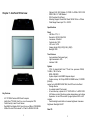
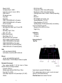
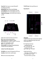
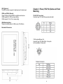
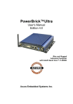
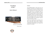
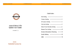
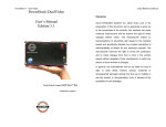
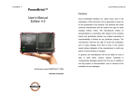
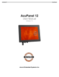
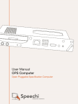
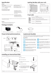
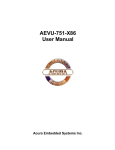
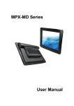
ACURA EMBEDDED SYSTEMS INC.
Rugged Panel PC
AcuPanel 19
User Manual
Revision 1.5
Contents
Chapter 1: AcuPanel 19 Overview
Specifications........................................................................................ 2
Knowing AcuPanel 19............................................................................ 4
Rear Top................................................................................................ 4
Rear Bottom .......................................................................................... 5
Rear Panel of AcuPanel19...…………………… .................................... 6
Mechanical Dimensions......................................................................... 7
Chapter 2: Power,PS/2 Port and Panel Mounting
12V-30V DC Power Input ......................................................................8
PS/2 Keyboard/Mouse Port ...................................................................8
Plugging the DC power Cable................................................................9
Panel Mounting.......................................................................................9
Chapter 3: BIOS Setup
About BIOS Setup ................................................................................11
Default Configuration ............................................................................12
Entering Setup ......................................................................................12
Legends.................................................................................................13
BIOS Setup Utility..................................................................................14
Main.......................................................................................................14
Advanced..............................................................................................15
IDE Configuration .................................................................................15
Intel IGD Configuration..........................................................................16
Save & Exit............................................................................................17
Acura Embedded Systems Inc.
Published Oct 29 2014
Chapter 1: AcuPanel19 Overview
.
.
.
.
.
Optional 3.5G / Wi-Fi Module / 2.5"HDD / 2x COMs / GPIO / DIO
DDR3 1GB / 2.5" HDD Bracket
IP65 Compliant Front Panel
Mounting Support: Panel/ Wall/ Stand/ VESA 100mm x 100mm
Wide Range Power Input 12V~ 30V DC
Specifications
Panel
. LED Size: 19", 4:3
. Resolution: SXGA 1280x1024
. Luminance: 350cd/m2
. Contrast ratio: 1000
. LCD color: 16.7M
. Viewing Angle: 80(U), 80(D), 85(L), 85(R)
. Backlight: LED
Touch Screen
. 5-wire resistive (flush panel type)
. Light transmission: 81%
. Interface: USB
Key Features
.
.
.
.
.
4:3 19" SXGA Fanless LED Panel Computer
Intel® Atom™ D2550, Dual Core, Low Consumption CPU
Flush Panel by 5-wire Touch Screen
Dual GbE/ 2nd display-VGA/ Line-in/ Line-out/ Mic-in/ PS2 KB/MS
USB x4/ 2x mini-PCIe sockets/ 1x CFast/ 2x RS232/ 422/ 485
1
System
. CPU: On-board Intel® Atom™ Dual Core processor D2550,
1.86GHz, 1M L2 Cache
. BIOS: AMI BIOS
. System chipset: Intel® NM10 Express chipset
. System memory: 2x 204-pin DDR3 SO-DIMM socket, 1G DDR3
(Default),
support up to 4GB DDR3-800/1066, Non-ECC and un-buffered
. Storage Device:
- 1x external locked CFast socket
- 1x hard drive bay: optional 1x 2.5" SATA HDD or 1x SATA DOM
. H/W status monitor: Monitoring system temperature, and voltage
. Expansion: 2x mini-PCIe sockets (support optional WiFi or 4G
module)
. Panel backlight control button: Increase brightness / decrease
brightness / Backlight On/Off
Rear I/O
2
. Ethernet: 2x RJ45
. 2nd display VGA port: 1x DB15
. Audio port: 1x Line out; 1x Line in; 1x MIC-in
. USB: 4x USB 2.0
. PS2 keyboard/ mouse
. Power switch
. Reset button
. COM #1: RS232/422/485 w/RI or 5V selection
. COM #2: RS232/422/485 w/RI or 12V selection
. DIO w/ 2.5kv isolated:
4x Digital Input (Source type)
- Input Voltage (Dry Contact): Logic 0: Close to GND
- Logic 1: Open
- Input Voltage: Logic 0: 3V max
- Logic 1: +5V ~ +30V
4x Digital Output (Sink type)
- Output Voltage: 3.6V ~ 5V
- Sink current: 200 mA max. per channel
. GPIO: 2x digital in/ 2x digital out (Optional)
. COM #1: RS232/422/485 w/ 2.5kv isolated
. COM #2: RS232/422/485 w/ 2.5kv isolated
. COM #3: RS232 w/ RI or 5V selection(Optional)
. COM #4: RS232 w/ RI or 12V selection(Optional)
- IEC 68 2-64 (w/ HDD)
- 1Grms @ sine, 5~500Hz, 1hr/axis (HDD Operating)
- 2Grms @ sine, 5~500Hz, 1hr/axis (CFast Operating)
- 2.2Grms @ random condition, 5~500Hz, 0.5hr/axis (Nonoperating)
. Shock:
- IEC 68 2-27
- HDD: 20G@wall mount, half sine, 11ms
. Operating temperature: -5°C to 50°C
. Storage temperature: -20°C to 75°C
. Operating humidity: 10%~90% relative humidity, non-condensing
Limits to be at 90% RH at max 50°C
. Dimension: 457.64 x 379.24 x 61.25 mm
. Weight: 6.5 Kg
Certifications
. CE approval
. FCC Class A
Knowing AcuPanel 19
Rear Top
Audio
. AC97 codec: Realtek ALC886-GR
. Audio interface: Line out/Line in/MIC-in Audio Jack
Ethernet
. LAN chip: dual Intel® 82574L Gigabit LAN
. Ethernet interface: 10/100/1000 Based-Tx Ethernet compatible
Mechanical & Environment
. Color: pantone black\RAL 15 00 front bezel w/ Pantone
400C\RAL 090 80 10 metal style membrane
. IP protection: IP65 front
. Mounting: panel/ wall/ stand/ VESA 100mm x 100mm
. Power input: 12V~ 30V DC
. Power adapter: Optional AC to DC power adaptor (+12V, 60W)
. Vibration:
3
Antenna holes for optional 4G/ WiFi/ Bluetooth
The 3 external antenna holes are used to mount and connect
optional 4G/ WiFi/ Bluetooth antennas.
CFast Card Socket Used to insert a CFast card.
4
Power Switch Press to power-on or power-off the panel PC.
Panel Backlight Control Buttons
Backlight On/Off Press to turn-on or turn-off the display
Increase Brightness Press to increase brightness of the screen.
Decrease Brightness Press to decrease brightness of the screen.
8 brightness level available: 30%, 40%, 50%, 60%, 70%, 80%, 90%
and 100%
12V-30V DC Input Used to plug a DC power cord.
Rear (AcuPanel19)
Rear Bottom
Line-in Used to connect an audio device as sound source.
Mic-in Used to connect an external microphone.
Line-out Used to connect a headphone or a speaker.
LAN 1 and LAN 2 Used to connect the system to a local area
network. LAN1 supports Wake up on LAN.
USB Used to connect USB 2.0/1.1 devices.
COM 1 and COM 2 These COM ports support RS232/422/485
compatible series device by BIOS setting.
AcuPanel 19 has 2.5kV isolated protection.
PS/2 KB/MS Used to connect a PS/2 keyboard and a PS/2 mouse
Reset Button Press this button to restart the system.
VGA Used to connect an analog VGA monitor.
5
DIO (Optional)
The digital I/O connector support 4 isolated protection digital input
channels and 4 isolated protection digital output channels.
Isolation voltage: 2500 VDC
DI: 4x Digital Input (Source Type)
- Input Voltage (Dry Contact)
Logic 0: Close to GND ; Logic 1: Open
- Input Voltage (Wet Contact)
Logic 0: 3V max. Logic 1: +5V-+30VDC
4x Digital Output (Sink Type)
- Output Voltage: Typical 24VDC, 30VDC max.
Logic 0: 0-0.6VDC Logic 1: 3.6-5VDC
- Sink Current: 200mA max. per channel
6
GPIO (Optional)
The GPIO connector supports 2 digital input and 2 digital output.
COM3 and COM4 (Optional)
These COM ports support RS232 compatible serial devices.
COM3 supports 5V or RI by Jumper setting.
COM4 supports 12V or RI by Jumper setting.
Chapter 2: Power, PS/2 Port,Cable and Panel
Mounting
12V-30V DC Power Input
Connector type: DC 4-pin DIN power jack with shield
VESA Mounting Holes
These are mounting holes for VESA mount (100x100mm).
Mechanical Dimensions
PS/2 Keyboard/Mouse Port
Connector type: PS/2, Mini-DIN-6, 2.0mm pitch
2x4 8-pin header, 2.54mm pitch
7
8
Plugging the DC Power Cable
1. Plug the DC 4-pin DIN power jack (male) into the DC 4-pin DIN
power jack (female) that is on the system. The table below shows the
pin definition of the cable.
4. Position the mounting clamps along the rear edges of the Panel PC.
The first and second clamps must be positioned and secured diagonally
prior to mounting the rest of the clamps. Tighten the clamp's screw until
it touches the panel.
Panel Mounting
1. Select a place on the panel where you will mount the Panel PC.
2. Cut out a shape on the panel that corresponds to the Panel PC's
rear dimensions.
The thickness of the
panel (e.g. steel
board, plank, acrylic
board, wall, etc.)
where you will mount
the Panel PC must
not exceed 6mm. If
the distance between
the front bezel and
panel mount hole is
too wide, it will not fit
the panel mount kit.
CAUTION!
Do not overtighten the screws to prevent damaging the Panel PC.
3. Slide the Panel PC through the hole until it is properly fitted against
the panel.
9
10
Chapter 3: BIOS Setup
This chapter describes how to use the BIOS setup program for the
AcuPanel 19. The BIOS screens provided in this chapter are for
reference only and may change if the BIOS is updated in the future.
About BIOS Setup
The BIOS (Basic Input and Output System) Setup program is a menu
driven utility that enables you to make changes to the system
configuration and tailor your system to suit your individual work
needs. It is a ROM-based configuration utility that displays the
system's configuration status and provides you with a tool to set
system parameters.
These parameters are stored in non-volatile battery-backed-up CMOS
RAM that saves this information even when the power is turned off.
When the system is turned back on, the system is configured with the
values found in CMOS.
With easy-to-use pull down menus, you can configure such items as:
. Hard drives, diskette drives, and peripherals
. Video display type and display options
. Password protection from unauthorized use
. Power management features
The settings made in the setup program affect how the computer
performs. It is important, therefore, first to try to understand all the
setup options, and second, to make settings appropriate for the way
you use the computer.
When to Configure the BIOS
. This program should be executed under the following conditions:
. When changing the system configuration
. When a configuration error is detected by the system and
you are prompted to make changes to the setup program
. When resetting the system clock
. When redefining the communication ports to prevent any conflicts
. When making changes to the Power Management configuration
11
. When changing the password or making other changes to the
security setup
Normally, CMOS setup is needed when the system hardware is not
consistent with the information contained in the CMOS RAM,
whenever the CMOS RAM has lost power, or the system features
need to be changed.
Default Configuration
Most of the configuration settings are either predefined
according to the Load Optimal Defaults settings which are stored
in the BIOS or are automatically detected and configured without
requiring any actions. There are a few settings that you may need to
change depending on your system configuration.
Entering Setup
When the system is powered on, the BIOS will enter the PowerOn Self Test (POST) routines. These routines perform various
diagnostic checks; if an error is encountered, the error will be reported
in one of two different ways:
. If the error occurs before the display device is initialized, a series of
beeps will be transmitted.
. If the error occurs after the display device is initialized, the
screen will display the error message.
Powering on the computer and immediately pressing <Del> allows
you to enter Setup. Another way to enter Setup is to power on the
computer and wait for the following message during the POST:
TO ENTER SETUP BEFORE BOOT PRESS
Press the
12
key to enter Setup:
Legends
that field. To display the submenu, move the highlight to that field and
press
.
BIOS Setup Utility
Once you enter the AMI BIOS Setup Utility, the Main Menu will
appear on the screen. The main menu allows you to select from
several setup functions and one exit. Use arrow keys to select among
the items and press
accept or enter the submenu.
Main
The Main menu is the first screen that you will see when you enter the
BIOS Setup Utility.
Scroll Bar
When a scroll bar appears to the right of the setup screen, it indicates
that there are more available fields not shown on the screen. Use
the up and down arrow keys to scroll through all the available fields.
Submenu
When " " appears on the left of a particular field, it indicates
that a submenu which contains additional options are available for
13
14
Advanced
The Advanced menu allows you to configure your system for basic
operation. Some entries are defaults required by the system board,
while others, if enabled, will improve the performance of your
system or let you set some features according to your preference.
Setting incorrect field values may cause the system to malfunction.
Intel® IGD Configuration
This section is used to configure the Intel® IGD Graphic configurations.
IDE Configuration
This section is used to configure the SATA as IDE or AHCI mode.
AHCI (default Setting)
This option configures the Serial ATA drives as Parallel ATA physical
storage device.
This option configures the Serial ATA drives to use AHCI (Advanced
Host Controller Interface). AHCI allows the storage driver to enable
the advanced Serial ATA features which will increase storage
performance.
15
16
IGFX – Boot Type
This field is used to configure which video device will be activated
during POST. This has no effect if external graphics present. The
options are CRT,LVDS, LVDS + CRT and CRT + HDMI.
Backlight Control Select
The available options are Pyroelectric sensor and Tact Switch. The
default setting is Tact Switch and the Backlight On/Off button is
functional only in this mode.+ CRT
Backlight On/Off Reverse
Please configure this option only when changing the panel, otherwise
the display may not work.
Backlight Dimming Control Select
The options are Tact Switch, Manual and Light sensor. and the
Backlight option below will be configurable.The default setting is Tact
Switch and the Backlight option below will not be configurable, please
use the brightness button on the panel to adjust it.
Backlight
Adjusts the brightness of the backlight.
To save the changes and reset, select this field then press <Enter>. A
dialog box will appear. Confirm by selecting Yes.
Technical Support:
Fixed Graphics Memory Size
contact Salesperson
This field is used to configure the memory size of the fixed graphics, the
options are 128MB and 256MB.
[email protected]
Mailing address: Acura Embedded Systems Inc.
Unit #1, 7711-128th Street, Surrey, BC V3W 4E6, CANADA
Ph: (604) 502-9666 Fax: (604) 502-9668
Save & Exit
Toll Free 1-866-502-9666
Save Changes and Reset
17
18