1
ZENO®-3200
User Manual
Version V2.02
June 27, 2003
P/N: 0302116012, Revision C
Michael J. Hart (Software Engineer)
COASTAL ENVIRONMENTAL SYSTEMS, Inc.
820 First Avenue South • Seattle, WA 98134
Telephone (206) 682-6048 • Fax (206) 682-5658
Web address: http://www.coastalenvironmental.com
Copyright © 2002 by Coastal Environmental Systems, Inc. All rights reserved.
ZENO®-3200
USER MANUAL
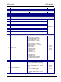
Table of Contents
TABLE OF CONTENTS ............................................................................................................................................ I
ACKNOWLEDGEMENTS ..................................................................................................................................... VI
1.
INTRODUCTION ..............................................................................................................................................1
1.1.
WHAT IS THE ZENO®-3200? .......................................................................................................................1
1.2.
HOW DOES THE ZENO®-3200 WORK? ........................................................................................................1
1.3.
ZENO®-3200 SPECIFICATIONS ......................................................................................................................2
1.3.1.
Analog Inputs ......................................................................................................................................2
1.3.2.
Digital I/O Ports..................................................................................................................................2
1.3.3.
Sensor and Auxiliary Power Outputs ..................................................................................................3
1.3.4.
Serial Communication Ports ...............................................................................................................3
1.3.5.
ADC Conversion Rates........................................................................................................................3
2.
ZENO®-3200 BASICS ........................................................................................................................................5
2.1.
THE ZENO®-3200 FRONT PANEL .................................................................................................................5
2.2.
COMMUNICATING WITH AND POWERING UP THE ZENO®-3200.....................................................................7
2.3.
ZENO®-3200 MEMORY.................................................................................................................................8
2.3.1.
RAM.....................................................................................................................................................9
2.3.2.
EEPROM.............................................................................................................................................9
2.4.
THE USER INTERFACE .................................................................................................................................10
2.4.1.
The User Interface Menu Structure...................................................................................................10
2.4.2.
Online Help .......................................................................................................................................11
2.5.
ZENO®-3200 FUNCTIONAL BLOCK DIAGRAM .............................................................................................12
3.
TUTORIAL: BASIC ZENO®-3200 OPERATION........................................................................................13
3.1.
PART ONE—HOW TO WORK WITH AN EXISTING CONFIGURATION ...........................................................13
3.1.1.
Looking At Logged Data ...................................................................................................................13
3.1.2.
Changing Output Message Format ...................................................................................................17
3.1.3.
Understanding & Changing the Sample Interval and Power Usage ................................................20
3.2.
PART TWO—LEARNING HOW TO CONFIGURE YOUR OWN ZENO®-3200 ..................................................23
3.2.1.
How Do I Configure The ZENO®-3200 To Perform My Requirements? ..........................................23
3.2.2.
Data Flow within the ZENO®-3200 ..................................................................................................24
3.2.3.
Learning How To Configure A Sensor ..............................................................................................27
3.2.4.
Learning How To Configure A Process ............................................................................................37
3.2.5.
Learning How To Configure A Data Output.....................................................................................43
3.2.6.
Other Configuration Changes ...........................................................................................................50
4.
RETRIEVING LOGGED DATA....................................................................................................................51
4.1.
DATA RETRIEVAL OPTIONS ........................................................................................................................52
4.1.1.
Communications Settings Affect How Data Records Are Viewed .....................................................53
4.1.2.
Viewing The Most Recently Logged Data Records ...........................................................................53
4.1.3.
Viewing & Marking The Oldest Data Records..................................................................................54
4.1.4.
Viewing All of The Logged Data Records .........................................................................................55
4.1.5.
Searching for Logged Data Records Based Upon Their Timestamps...............................................55
4.1.6.
Downloading Data Records Into A File As A Text Dump.................................................................56
4.1.7.
Downloading Data Records Into A File Using The X-Modem Protocol...........................................56
4.2.
DATA LOGGING CAPACITY INFORMATION ..................................................................................................57
4.3.
DELETING LOGGED DATA RECORDS ...........................................................................................................58
4.4.
DATA OUTPUT MESSAGE FORMAT OPTIONS ...............................................................................................58
4.4.1.
Retrieved Data Output Message Format...........................................................................................59
Coastal Environmental Systems (206) 682-6048
Page i
ZENO®-3200
USER MANUAL
4.4.2.
Real Time Data Output Message Format..........................................................................................60
4.5.
BAD SENSOR VALUE REPLACEMENT ..........................................................................................................60
4.6.
THE CCSAIL COMMUNICATIONS PROTOCOL ..............................................................................................61
4.6.1.
The Structure of a CCSAIL Framed Message ...................................................................................62
4.6.2.
The ZENO®-3200's Response to a CCSAIL Message........................................................................63
4.6.3.
CCSAIL Data Retrieval Commands ..................................................................................................64
4.6.4.
Intercept™ and Data Records Transmitted In CCSAIL Format.......................................................65
4.7.
OPTIONAL FLASH LOGGING MEMORY ........................................................................................................66
4.7.1.
How Flash Logging Memory Differs From RAM..............................................................................66
4.7.2.
Retrieving Flash Logging Memory Status.........................................................................................68
5.
INTERNAL ZENO®-3200 SETTINGS...........................................................................................................69
5.1.
5.2.
5.3.
5.4.
5.5.
5.6.
5.7.
5.8.
6.
ZENO®-3200 SYSTEM DATE AND TIME .....................................................................................................70
CALIBRATING INTERNAL TEMPERATURE SENSOR .......................................................................................70
GETTING CURRENT ZENOSOFT® VERSION NUMBER ................................................................................71
CONTACT INFORMATION .............................................................................................................................71
ZENO®-3200 IDENTIFICATION NUMBER, THE PRIMARY UNIT ID ..............................................................71
A DESTINATION IDENTIFICATION NUMBER, THE SECONDARY UNIT ID ......................................................72
COMPASS SENSOR USAGE ...........................................................................................................................73
BAROMETER ELEVATION SETTING ..............................................................................................................73
COMMUNICATION INTERFACES.............................................................................................................74
6.1.
BASIC COMMUNICATIONS SETTINGS ............................................................................................................75
6.2.
DIRECT TERMINAL ACCESS ........................................................................................................................79
6.3.
HARDWARE HANDSHAKING ........................................................................................................................79
6.4.
TELEPHONE MODEMS .................................................................................................................................80
6.4.1.
ZENO®-3200 Modem Configuration.................................................................................................80
6.4.2.
MODEM SETTINGS .........................................................................................................................83
6.4.3.
CABLE PIN-OUTS............................................................................................................................87
6.5.
CELLULAR MODEMS ....................................................................................................................................88
6.5.1.
AMPS Cellular Modem Configuration (StarComm Cellular Modem) ..............................................90
6.5.2.
AMPS Cellular Modem Network Activation......................................................................................90
6.5.3.
Understanding CDPD Cellular Modems ..........................................................................................91
6.5.4.
Sierra Wireless MP200 Sample Configuration .................................................................................93
6.6.
RADIO COMMUNICATIONS ...........................................................................................................................94
6.6.1.
Connecting the Radio To The ZENO®-3200 .....................................................................................95
6.6.2.
Power Control Options .....................................................................................................................96
6.6.3.
Controlling Unidirectional Radio Power (The Power Control Menu) .............................................96
6.6.4.
Controlling Bi-directional Radio Power (The Digital Output Menu) ...............................................97
6.6.5.
Push-To-Talk (PTT) ..........................................................................................................................99
6.6.6.
Response Delay Time ........................................................................................................................99
6.6.7.
Data Packetization ..........................................................................................................................100
6.7.
GOES SATELLITE COMMUNICATIONS............................................................................................100
6.7.1.
Obtaining GOES Channels .............................................................................................................100
6.7.2.
Data Download ...............................................................................................................................101
6.7.3.
DAPS Dial-in Procedure.................................................................................................................102
6.7.4.
TELONICS TGT-1 GOES TRANSMITTER .....................................................................................105
6.7.5.
Campbell Scientific SAT HDR GOES Transmitter..........................................................................106
6.7.6.
ZENO®-3200 Configuration............................................................................................................106
6.7.7.
Connecting A GOES Radio and Serial Sensors To The Same COM Port.......................................109
6.7.8.
GOES Transmitter Diagnostics.......................................................................................................109
6.7.9.
Self-Timed Transmissions ...............................................................................................................109
6.7.10.
Random Transmissions ...................................................................................................................109
6.7.11.
GOES Binary Format......................................................................................................................109
6.8.
ARGOS SATELLITE COMMUNICATION ......................................................................................................110
Coastal Environmental Systems (206) 682-6048
Page ii
ZENO®-3200
USER MANUAL
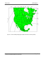
6.8.1.
Applying To Use ARGOS ................................................................................................................111
6.8.2.
ARGOS Coverage............................................................................................................................111
6.8.3.
Data Recovery .................................................................................................................................111
6.8.4.
Connecting The Telonics ST-13 ARGOS PTT With The ZENO®-3200 ...........................................112
6.8.5.
ZENO®-3200 Configuration............................................................................................................112
6.8.6.
ARGOS Binary Format ...................................................................................................................114
6.9.
PASSTHROUGH MODES .............................................................................................................................114
6.9.1.
Terminal Passthrough Mode ...........................................................................................................115
6.9.2.
SDI-12 Passthrough Mode ..............................................................................................................117
6.9.3.
Configuring the Passthrough Mode Escape Character ..................................................................118
6.10. REPEATER CAPABILITY .............................................................................................................................120
6.11. SPEECH INTERFACE CAPABILITY ...............................................................................................................123
6.11.1.
Overview..........................................................................................................................................124
6.11.2.
Creating A Spoken Output Message................................................................................................124
6.11.3.
Defining The Speech/Modem Ports and Control Lines...................................................................127
6.11.4.
Wiring Diagram ..............................................................................................................................129
6.12. OPTIONAL ACCESS CONTROL CUSTOMIZATION TO THE USER INTERFACE ...............................................130
7.
MONITORING & CALIBRATING SENSOR DATA................................................................................132
7.1.
7.2.
7.3.
7.4.
7.5.
7.6.
8.
ZENO®-3200 ACCESS PRIVILEGES .........................................................................................................138
8.1.
8.2.
9.
MONITORING RAW OR SCALED SENSOR DATA .........................................................................................132
SCALING (CALIBRATING) RAW SENSOR DATA ..........................................................................................133
VIEWING PROCESS RECORD DATA ............................................................................................................134
VIEWING SENSOR ERROR & STATUS CODES .............................................................................................134
VIEWING SENSOR & PROCESS RECORD DATA COLLECTION COUNTERS ...................................................135
DISPLAYING GLOBAL BUILT-IN-TEST (BIT) STATUS ................................................................................137
ACCESSING THE ZENO PROGRAM MENU ...................................................................................................138
SETTING ACCESS PRIVILEGES ....................................................................................................................139
UPLOADING AND DOWNLOADING AN ENTIRE CONFIGURATION ............................................141
9.1.
9.2.
9.3.
9.4.
DOWNLOADING A CONFIGURATION TO YOUR COMPUTER .......................................................................141
UPLOADING A CONFIGURATION TO YOUR ZENO®-3200 .........................................................................143
VIEWING A CONFIGURATION WITH ALL MENUS ......................................................................................144
CONFIGURATION FILE COMPATIBILITY BETWEEN DIFFERENT ZENOSOFT® VERSIONS ..........................145
10. ZENO®-3200 CONFIGURATION SPECIFICS ..........................................................................................147
10.1. ZENO®-3200 CONFIGURATION TIPS .........................................................................................................147
10.2. COMMON SENSOR, PROCESS AND DATA OUTPUT MENU COMMANDS .......................................................148
10.3. DEFINING THE SENSORS ............................................................................................................................148
10.3.1.
Analog Sensors................................................................................................................................150
10.3.2.
Digital Sensors ................................................................................................................................153
10.3.3.
Serial Sensor Background...............................................................................................................155
10.3.4.
Specifics for Each Supported Serial Sensor Type ...........................................................................156
10.3.5.
Configuring A Serial Sensor ...........................................................................................................161
10.3.6.
User-Specified Sensor Name ...........................................................................................................165
10.3.7.
Setting How Often To Read A Sensor--The Sensor Timing Loop....................................................165
10.3.8.
Setting The Maximum Number of Readings ....................................................................................167
10.3.9.
Setting Number of Measurements To Take--Sensor Sample Count.................................................167
10.3.10.
Using Switched Voltage To Control Sensor Power ....................................................................168
10.3.11.
Specifying Warm-up Time for a Sensor Using Switched Voltage ...............................................169
10.3.12.
Using Excitation Voltage and Returns To Control Sensor Power ..............................................170
10.3.13.
Setting Scaling (Calibration) Coefficients ..................................................................................171
10.4. DEFINING THE DATA PROCESSES ..............................................................................................................173
10.4.1.
Process Category and Process Number ..........................................................................................174
Coastal Environmental Systems (206) 682-6048
Page iii
ZENO®-3200
USER MANUAL
10.4.2.
User-Defined Process Name ...........................................................................................................177
10.4.3.
Selecting the Appropriate Processes ...............................................................................................177
10.4.4.
Unique Data Inputs and User Inputs for Each Process ..................................................................178
10.4.5.
Process Error Checking and Reporting ..........................................................................................179
10.5. DEFINING CONSTANTS ..............................................................................................................................180
10.6. DEFINING DATA TO BE TRANSMITTED AND/OR LOGGED ....................................................................181
10.6.1.
Data Record Structure ....................................................................................................................181
10.6.2.
Output Message Structure ...............................................................................................................183
10.6.3.
The Different Types of Data Output Records ..................................................................................184
10.6.4.
Setting Which Output Message Uses Which Data Output Record ..................................................187
10.6.5.
The Data Output Record Field Name--A Columnar Heading Or A Literal String .........................188
10.6.6.
Setting Up A Data Output Record To Transmit And/Or Log Data .................................................190
10.6.7.
Creating An Automatic Output Message for CCSAIL Format ........................................................194
10.6.8.
Creating An Automatic Output Message in NMEA 0183 Format ...................................................195
10.6.9.
Conditional Message Fragments.....................................................................................................196
10.6.10.
Selecting Data To Log & Transmit Via Output Message Number..............................................198
10.7. SETTING OUTPUT MESSAGE SCHEDULES AND DESTINATIONS ....................................................................199
10.7.1.
Selecting the Communications Port for Each Output Message ......................................................200
10.7.2.
Specifying the Time of Transmission for Each Output Message .....................................................200
10.8. RESETTING (REBOOTING) THE ZENO®-3200...........................................................................................203
11. ALARM MESSAGES ....................................................................................................................................205
11.1. CONFIGURING AN ALARM CONDITION......................................................................................................206
11.2. CREATING AN ALARM MESSAGE ..............................................................................................................207
11.2.1.
Transmitting Your Regular Output Message As An Alarm Message ..............................................208
11.2.2.
Using Conditional Message Fragments In An Alarm Message ......................................................208
11.2.3.
Transmitting A Unique Alarm Message ..........................................................................................208
11.3. CONFIGURING THE ZENO®-3200 TO TRANSMIT (AND POSSIBLY LOG) AN ALARM MESSAGE ................209
11.3.1.
Selecting The Communications Port To Transmit The Alarm Message..........................................210
11.3.2.
Dialing-out An Alarm Message Via A Telephone Or Cellular Modem...........................................210
11.3.3.
Transmitting An Alarm Message Via A GOES Transmitter ............................................................211
11.3.4.
Transmitting An Alarm Message Via An ARGOS Transmitter........................................................212
12. ADVANCED ZENO®-3200 CONFIGURATION TOPICS ........................................................................214
12.1. UNDERSTANDING ZENO®-3200 TIMING ..................................................................................................214
12.1.1.
ZENO®-3200 Timing Structure .......................................................................................................214
12.1.2.
The ZENO®-3200 Internal Clock ....................................................................................................215
12.1.3.
The Real Time Operating System ....................................................................................................215
12.1.4.
ZENOSOFT® and Multitasking .......................................................................................................216
12.1.5.
The User-Defined Configuration and Timing .................................................................................216
12.1.6.
Multiple Sensors and Timing...........................................................................................................219
12.1.7.
Calculating The Total Time Required for The ZENO®-3200 To Measure All Sensor Records ......219
12.1.8.
Multiple Sensors Sharing The Same Resource and Timing.............................................................220
12.1.9.
Timing and Effects Upon The User Interface..................................................................................223
12.2. THE UNIVERSAL SERIAL INTERFACE .........................................................................................................224
12.2.1.
Three Menus Are Used To Configure The USI ...............................................................................224
12.2.2.
The Sensor Menu.............................................................................................................................224
12.2.3.
The General Serial Script Menu (In Brief)......................................................................................226
12.2.4.
The Memory Management Menu.....................................................................................................227
12.2.5.
Changing Script Record Command Lines .......................................................................................228
12.2.6.
Library of USI Commands ..............................................................................................................230
12.2.7.
Writing & Troubleshooting A USI Script ........................................................................................236
12.3. CONFIGURATIONS WITH MULTIPLE SERIAL SENSORS ...............................................................................238
12.4. SHARING DATA BETWEEN MULTIPLE ZENO®-3200'S (MULTIPROCESSING).............................................239
Coastal Environmental Systems (206) 682-6048
Page iv
ZENO®-3200
USER MANUAL
13. ELECTRICAL CONSIDERATIONS ..........................................................................................................241
13.1. THE ZENO®-3200 ENCLOSURE ................................................................................................................241
13.2. GROUNDING ..............................................................................................................................................241
13.3. CONNECTING DIFFERENTIAL INPUTS .........................................................................................................243
13.4. THE ZENO®-3200 CPU BOARD ...............................................................................................................245
13.5. SERIAL PORT WIRING ...............................................................................................................................245
13.5.1.
COM3 RS232 SERIAL PORT..........................................................................................................246
13.5.2.
AUXILIARY SERIAL PORT ............................................................................................................247
13.5.3.
Revision A and Revision D, ZENO®-3200 Communication Wiring Setups.....................................249
A.
CONSTANTS, CONVERSIONS & ASCII TABLE................................................................................... A-1
B.
ZENO®-3200 MENU LISTING.....................................................................................................................B-1
C.
SENSOR CONFIGURATIONS ................................................................................................................... C-1
D.
ZENO®-3200 PROCESS LIBRARY............................................................................................................ D-1
E.
CONFIGURATION FILE CONTENTS ......................................................................................................E-1
F.
LIBRARY OF CCSAIL COMMANDS........................................................................................................F-1
G.
INDEX ............................................................................................................................................................ G-1
Coastal Environmental Systems (206) 682-6048
Page v
ZENO®-3200
USER MANUAL
Acknowledgements
The author, Michael J. Hart, personally thanks each of the individuals listed below for their assistance to
ensure the accuracy of information and overall readability of the ZENO®-3200 User Manual. Your
contributions are greatly appreciated.
•
Daine Buckshnis (Editor): exhaustive grammatical review.
•
Paul Danilchik (Electrical Engineer): provided technical information.
•
De Ellefsen (Electrical Engineer): technical review.
•
Pete Fox (Editor): exhaustive grammatical review and text editing.
•
Dubravko "Woody" Kauzlaric (Communications Engineer): technical review.
•
Heather Parsons (Editor): exhaustive page formatting.
•
Dr. Susan Tonkin (Physicist, former Vice President of Engineering and former President of Coastal
Environmental Systems): maintained original ZENO®-3200 User Manual, upon which this manual is
based.
•
Amir Varamini (Production Manager): technical review.
Coastal Environmental Systems (206) 682-6048
Page vi
ZENO®-3200
1.
USER MANUAL
INTRODUCTION
Coastal Environmental Systems
ZENO®-3200 User Manual
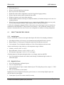
WHAT IS THE ZENO®-3200?
1.1.
The ZENO®-3200 is the world's first intelligent, versatile, low-power, 32-bit data acquisition system
designed to collect, process, store and transmit data from multiple sensors. Its mechanical versatility and
low power requirements allow the ZENO®-3200 to operate independently and remotely in a wide range of
environmental extremes that include polar ice sheets, ocean buoys and windy mountaintops.
The ZENO®-3200's advanced firmware, ZENOSOFT®, contains extensive libraries of sensor types, data
processes, and data output options that allow each ZENO®-3200 to be configured to meet a variety of
requirements. The built-in, help-assisted menus contained in ZENOSOFT® let you configure the ZENO®3200 with ease. The ZENOSOFT® libraries are continually being expanded. Contact Coastal
Environmental Systems if your particular application is not discussed in this User Manual.
The related Intercept™ program1 collects, displays, and forwards all data from the ZENO®-3200.
Through Intercept™, data can be directly shared with other Microsoft Windows™ application programs.
for further information, please refer to Coastal Environmental Systems’ Intercept™ documentation.
HOW DOES THE ZENO®-3200 WORK?
1.2.
The ZENO®-3200 carries out three primary functions via its built-in firmware, ZENOSOFT®, in a regular
and timely fashion according to the configuration defined within the ZENO®-3200 memory:
1. Collect data from the sensors.
2. Process the collected data.
3. Log into RAM and/or transmit the processed and collected data.
ZENOSOFT® operates within a Real Time Operating System (RTOS) that is controlled by the ZENO®3200's built-in clock. The RTOS allows multiple tasks to be performed concurrently and
deterministically by the ZENO®-3200's single Central Processing Unit (CPU). This ensures that the
ZENO®-3200 precisely performs its primary functions in accordance with the user's instructions stored in
the configuration.
The ZENO®-3200 configuration is a set of information created by the user that tells the ZENO®-3200:
•
1
How many sensors to collect data from.
Intercept™, produced by Coastal Environmental Systems, is a Microsoft Windows™ application.
Coastal Environmental Systems (206) 682-6048
Page 1
ZENO®-3200
USER MANUAL
•
What each sensor is.
•
When to collect the data from each sensor.
•
How to process the collected data.
•
Which data values define a single data record to be logged into logging memory.
•
When to log into memory and/or transmit the data record.
•
Whether to generate one or more alarm messages.
•
Which telephone numbers to dial (up to 4 telephone numbers), if an alarm message is to be sent via a
telephone modem.
•
What (if any) types of communication devices are connected to the ZENO®-3200 (a one-way radio,
two-way radio, telephone modem, cellular modem, GOES or ARGOS transmitter).
To define the configuration within the ZENO®-3200 (and to retrieve data logged), the user interactively
communicates with ZENOSOFT® using its built-in user interface. The user interface contains a set of
interactive menus that allow the user to create a new configuration or modify an existing configuration.
1.3.
ZENO®-3200 SPECIFICATIONS
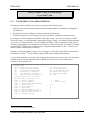
1.3.1. Analog Inputs
Seven (7) differential or fourteen (14) single-ended inputs offer choices for sampling performance.
•
Ultra-high resolution: ±18-bit at up to two channels/second with 50/60 Hz noise rejection.
•
High resolution: ±15-bit at up to 10 channels/second with 50/60 Hz noise rejection.
•
Low resolution: Two (2) channels available at ±12-bit A/D at 10,000 conversions/second.
Accuracy and linearity are provided over a wide temperature range as follows:
•
Linearity: ±0.001% (-40°C to +60°C).
•
Basic radiometric accuracy: ±0.05% (-40°C to +60°C).
•
Wide dynamic input range: ±5 mV to ±5 V in 10 ranges.
All analog inputs are fault-protected against shorts, overvoltages, transients and ESD.
•
Up to four multiplexer boards can be added, each allowing 32 additional single-ended or 16
differential inputs.
1.3.2. Digital I/O Ports
•
Six (6) Schmidt trigger conditioned inputs.
•
Two (2) comparator inputs.
•
Six (6) general purpose input or output channels (inputs TTL with pull up resistor, outputs 1 - 5 VDC
high impedance).
•
One (1) switch closure (event counter).
Digital inputs can be configured for frequency, period, count, or event counting. Digital outputs can
provide control or alarm signals.
•
Count inputs: Up to 65536 counts at 0.005% accuracy.
Coastal Environmental Systems (206) 682-6048
Page 2
ZENO®-3200
•
USER MANUAL
Frequency inputs: Up to 100 kHz at 0.005% accuracy.
1.3.3. Sensor and Auxiliary Power Outputs
•
Sensor excitation: Five switched excitation outputs for software selectable voltages of 1.25, 2.50,
5.00, with basic accuracy of 0.01% at up to 100 mA. Long-term stability of 20 ppm over 1000 hours,
with most of the drift occurring within the first 100 hours.
•
Reference outputs: one fixed, for sensor signal offsets.
•
Power outputs (switched).
•
Three channels of +12V; one channel at 700 mA; two channels at 150 mA.
•
Two channels of +5V at total 600 mA peak, 200 mA mean.
•
Other power output: optional.
•
Optional digital-to-analog expansion board gives 4 or 8 channels of individually programmable 12-bit
analog output at 0 to 5 V. 2
1.3.4. Serial Communication Ports
•
Three serial communication ports labeled as COM1, COM2 and COM3.
•
Baud rates: each serial communications port supports baud rates of 300, 600, 1200, 2400, 4800, 9600
and 19,200 bits per second (bps).
•
COM1 supports RS232, RS232H 3, and unidirectional and bi-directional radio communications.
•
COM2 supports RS232, RS232H, RS485, GOES satellite transmitters4 and ARGOS satellite
transmitters.5 COM2 is fully multiplexed.6
•
COM3 supports RS232, RS232H, RS485 and RS422.
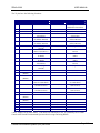
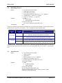
1.3.5. ADC Conversion Rates
The ZENO®-3200 has two A/D converters: one referred to as 12-bit, and one referred to as 18-bit. The
12-bit ADC is very fast, with up to 10,000 samples per second. The main limitation on your use of the
12-bit ADC is the fact that only two terminal block connections are available.
A single conversion on the 18-bit ADC requires approximately 100 milliseconds, which equates to 10
samples per second. This always outputs a signed 18-bit value, but the least significant 3 bits are highly
susceptible to noise and may not be accurate. Hence, a single sample has 15-bit accuracy. To obtain full
18-bit accuracy, three values must be averaged by setting the Sensor Sample Count in the Sensor Menu to
three.7 This brings the sample rate down to no more than three samples per second.
Therefore, the maximum possible sample rate -- including all sensors -- is a total of 16 samples per
second at an effective 15 bits of resolution, or 2 samples per second at a full 18 bits of resolution.
2
Other voltage ranges are optional.
RS232H is half-duplex RS232.
4
Refer to Section 6.7.
5
Refer to Section 6.8.
6
Refer to Section 6.1.
7
Refer to Section 10.3.1.
3
Coastal Environmental Systems (206) 682-6048
Page 3
ZENO®-3200
USER MANUAL
In practice, the best available sample rate is often rather lower than this. If multiple sensors are being
read, with different excitation voltages or powers, the ZENO®-3200 must wait for the system to settle
before beginning a conversion. Because the ZENO®-3200 is a multi-tasking system8, if a great deal of
processing or message-transmission is required, then the CPU cannot revisit the ADC task immediately
once each conversion is complete. A typical maximum sample rate is 10 samples per second at 15 bits.
8
Refer to Section 12.1.4.
Coastal Environmental Systems (206) 682-6048
Page 4
ZENO®-3200
2.
USER MANUAL
ZENO®-3200 BASICS
Coastal Environmental Systems
ZENO®-3200 User Manual
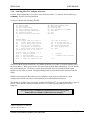
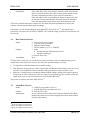
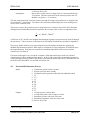
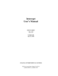
2.1.
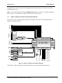
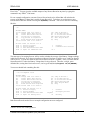
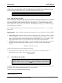
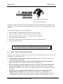
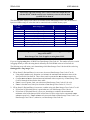
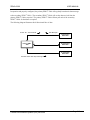
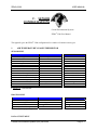
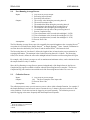
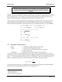
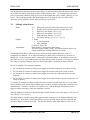
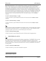
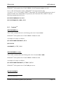
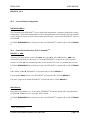
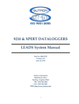
THE ZENO®-3200 FRONT PANEL
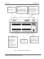
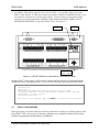
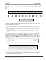
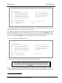
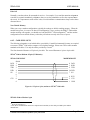
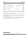
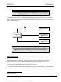
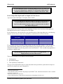
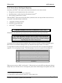
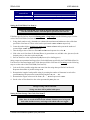
The ZENO®-3200 Front Panel, illustrated in , allows easy access to nearly all external connections to the
ZENO®-3200.
Only a 1/8-inch screwdriver9 is required to attach wires to connections along the four terminal strips. The
four terminal strips organize the external connections into the following groups:
•
Analog Outputs and Grounds
•
Analog Sensor Inputs
•
Serial Data, Power and Grounds
•
Digital Inputs and Outputs
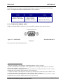
The Serial Communications Port that is usually used for computer access, COM3 (a two-row, 9-pin, DE-9
connector), is located on the top, far right-hand side of the front panel. COM3 is sometimes referred to as
the Maintenance Port.
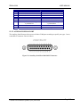
The Auxiliary Serial Port (the two-row, 25-pin, DB-25 connector) is located to the left of COM3.
Various connections for radio communication (both RS232 and TTL) as well as standard RS232
communications are available on this port. (Details about this port are located in Section 13.5.2 of this
User Manual.)
The Analog Expansion Port, (the two-row, 15-pin, DA-15 connector), located on the top, far left-hand
side of the front panel, is currently not in use.
9
This is equivalent to a 3-millimeter screwdriver.
Coastal Environmental Systems (206) 682-6048
Page 5
ZENO®-3200
USER MANUAL
Serial communications
Analog outputs
Data storage
Regulated power and
reference sensor drivers.
Single on-board, battery-backed
memory chip with 64 kbyte to 1
Mbyte memory. Up to 8 Mbyte of
flash logging memory is available.
Three hardware UART ports with
multi-plexing capability to
intelligent sensors, additional linked
ZENO®s, other systems or
communication devices.
Control outputs
A/D inputs/conversions
14 analog inputs with
variable (±15 to ±18-bit)
conversion increasing
accuracy over large
dy-namic ranges.
Digital I/O ports
Up to 15 channels.
Using up to 6 control
outputs, the ZENO®-3200
makes decisions affecting
related devices or signal
outputs.
Two additional channels
sample with 12-bit resolution
at up to 10,000 times per
second.
Figure 2-1. ZENO®-3200 Front Panel Diagram
Coastal Environmental Systems (206) 682-6048
Page 6
ZENO®-3200
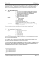
2.2.
USER MANUAL
COMMUNICATING WITH AND POWERING UP THE ZENO®-3200
You will need four things to begin communicating with ZENO®-3200:
1. Communication with the ZENO®-3200 is done via a PC, a Macintosh or any other computer running
a standard, commercially available terminal emulation program (such as Crosstalk, Mirror, Microsoft
Windows® Terminal, Microsoft Windows® Hyperterminal, or ProComm®).
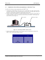
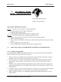
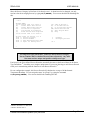
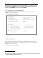
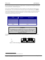
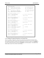
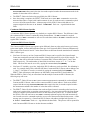
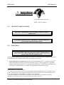
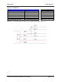
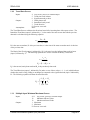
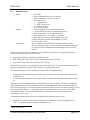
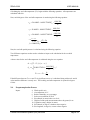
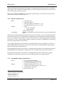
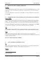
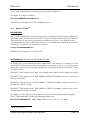
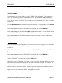
2. Using the interface cable supplied by Coastal Environmental Systems, connect the computer's RS-232
serial port to the DE-9 (9-pin, 2-row connector) located at the top of the ZENO®-3200 faceplate and
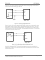
termed COM3 (refer to Figure 2-2).
PC serial port
ZENO port COM3
Figure 2-2. Connecting the ZENO®-3200 to your PC.
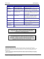
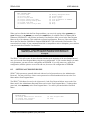
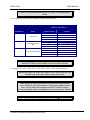
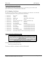
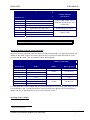
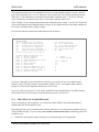
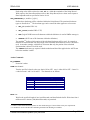
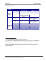
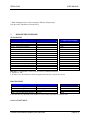
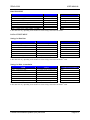
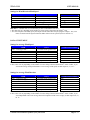
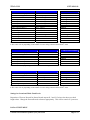
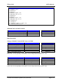
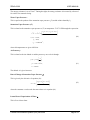
3. Start the terminal emulation program on your computer and set its communication settings to the
ZENO®-3200's COM3 default settings as follows:
Computer's Serial Port Setting
Baud Rate
Data Bits
Start Bits
Stop Bits
Parity
Flow Control
Coastal Environmental Systems (206) 682-6048
Default ZENO®-3200
Value
9600
8
1
1
None
None
Page 7
ZENO®-3200
USER MANUAL
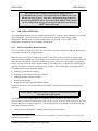
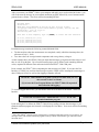
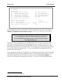
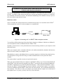
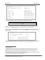
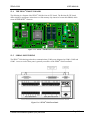
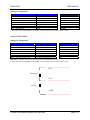
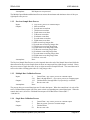
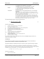
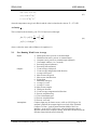
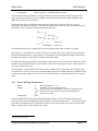
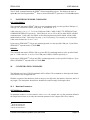
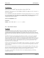
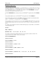
4. The ZENO®-3200 requires a power source of 10 to16 VDC. You can either apply power to the
ZENO®-3200 using the 12 VDC power adapter provided by Coastal Environmental Systems, or you
can connect to your own 10 to 16 VDC power supply. If you are using your own power supply,
connect power to the points labeled "POWER" on the terminal strip labeled "SERIAL DATA,
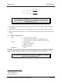
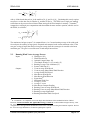
POWER AND GROUNDS" on top of the ZENO®-3200. See Figure 2-3.
Power (+/-)
COM3 port
DC power
plug (+ center)
Figure 2-3. ZENO®-3200 Power Connections & Connecting to COM3.
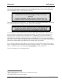
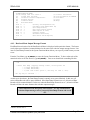
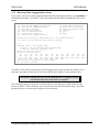
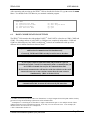
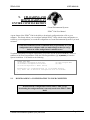
With the ZENO®-3200 properly connected to the computer and the computer is running the terminal
emulation program, upon applying power, you will see the following text generated by ZENOSOFT®:
Watchdog Reset
Please wait.../
ZENO-3200 using ZENOSOFT V1.964 Jun 28 2001 15:41:01 CS 96CC
(C)opyright 1995-2001, Coastal Environmental Systems, Seattle, WA, USA.
System Time = 01/07/11 13:47:31
Initializing Zeno 3200 .../
Zeno 3200 is Data Sampling. Type 'U'{ENTER} to access the User Interface.
2.3.
ZENO®-3200 MEMORY
Before proceeding, a brief discussion is provided to explain the two main types of memory that are used
in the ZENO®-3200. The two types of memory are Random Access Memory (RAM) and Electrically
Erasable Programmable Read Only Memory (EEPROM).
Coastal Environmental Systems (206) 682-6048
Page 8
ZENO®-3200
USER MANUAL
2.3.1. RAM
Each ZENO®-3200 is shipped with a minimum of 256 kilobytes of static RAM.10 The RAM is the
working memory in the ZENO®-3200. It is used to store the active configuration, the logged data records
and the internal data that is used by ZENOSOFT® to perform the operations necessary for the active
configuration.
Since the ZENO®-3200 is used in harsh environments, there is a possibility that there will be momentary
losses of power to the ZENO®-3200. Since RAM cannot maintain its stored contents during a power loss,
the ZENO®-3200 contains a small battery to maintain power to the RAM, allowing it to maintain its
contents during the power loss.11
The battery used to back up RAM in the ZENO®-3200 lasts approximately 10 years. Eventually, it will
discharge to a point where it can no longer provide enough power for the RAM to be maintained during a
momentary power disruption and the data stored in RAM will be lost. It is for this reason that the second
type of memory, EEPROM, is used in the ZENO®-3200.
2.3.2. EEPROM
Unlike RAM, EEPROM does not require constant power to maintain its contents. Hence, the data stored
in EEPROM remains intact regardless of any power loss. The size of the EEPROM is very small, though,
in comparison to RAM. A Revision-A ZENO®-3200 will contain 2 kilobytes of EEPROM, but a
Revision-D ZENO®-3200 will contain 8 kilobytes of EEPROM.
Because EEPROM is a very safe type of memory storage, EEPROM is used by the ZENO®-3200 to store
the configuration. The ZENO®-3200 stores the configuration in a condensed format in the EEPROM
since it is much smaller than RAM.
ZENOSOFT® does not use the configuration stored in EEPROM during its normal operations because the
condensed configuration stored in EEPROM is not in a useable form.12
One of the first things that ZENOSOFT® does when the ZENO®-3200 is turned on is to read and expand
the condensed configuration stored in EEPROM, then store the expanded (useable) configuration in RAM
for use during normal operations.
When you create a new configuration or modify an existing configuration, you are changing the
configuration stored in RAM, not EEPROM.
10
Formerly, the minimum amount of installed RAM was 64 kilobytes. Refer to Section 13.4 for the location of the
RAM on the main CPU board.
11
The battery acts like a miniature UPS, or Uninterrupted Power Supply, to the RAM.
12
This is analogous to a file that has been shrunk on a personal computer using a zip program.
Coastal Environmental Systems (206) 682-6048
Page 9
ZENO®-3200
USER MANUAL
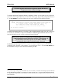
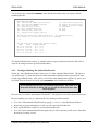
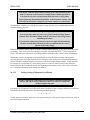
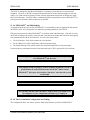
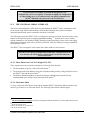
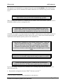
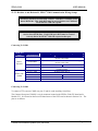
Once you are done creating or modifying the configuration, it is
recommended that you save your configuration to EEPROM in the event
that there is a loss of power. Only those configuration changes that have
been stored in EEPROM will be retrieved when the ZENO®-3200 is turned
on. Any configuration changes stored only in RAM will be lost when the
ZENO®-3200 is turned off.
2.4.
THE USER INTERFACE
Once communications between your computer and the ZENO®-3200 have been established, you can enter
the User Interface. The User Interface is a text-based menu system provided entirely within
ZENOSOFT® that allows easy retrieval of logged data, easy creation of a new ZENO®-3200
configuration, or modification of an existing configuration.13
2.4.1. The User Interface Menu Structure
The User Interface is divided into two levels: the lower level menus called the User Menus and the upper
level menus called the Zeno Program Menus.
When the user accesses the User Menus, the ZENO®-3200 will continue to perform its primary data
collection functions unhindered. Some changes to the configuration can be made in submenus of the User
Menu, but none that directly impact the definitions of sensors, processes or the contents of logged data
records. for this reason, the factory default setting for User Menu access is unprotected--meaning that no
password is required to access any of the lower level menus. The functions that can be performed via
User Menu and its various submenus include:
•
Changing communications settings.
•
Changing system settings such as the clock time.
•
Changing the data collection schedule.
•
Retrieving logged data.
•
Inspecting raw sensor data and calibrate sensors.
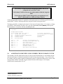
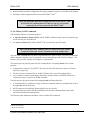
If the user accesses the Zeno Program Menus, the ZENO®-3200 suspends all primary data collection
functions.
If your ZENO®-3200 arrives factory-configured, you should never need to
enter the Zeno Program Menu.
The submenus of Zeno Program Menu are designed to directly modify the definitions of sensors,
processes and the contents of logged data records. for this reason, the factory default setting for the Zeno
Program Menu access requires a password. The functions that can be performed via the Zeno Program
Menu and its submenus include:
•
Changes to sensor definitions, including addition or deletion of sensors.
13
You do not need to install any special software on your computer to use the User Interface. Just use your same
terminal emulation program!
Coastal Environmental Systems (206) 682-6048
Page 10
ZENO®-3200
USER MANUAL
•
Changes to process definitions, including addition or deletion of processes.
•
Changes to logged data record definitions, including addition or deletion of specific data values to the
data record.
•
Uploading an entire configuration file from a computer, or downloading an entire configuration to a
computer.
•
Changing User Menu and Zeno Program Menu access passwords.
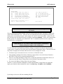
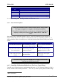
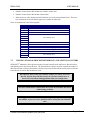
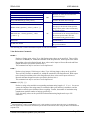
A complete listing of the User Interface menu structure is provided in Appendix B. An abridged menu
listing is provided below.
User Menu
Communications Menu
System Functions Menu
Sample Period Menu
Data Retrieval Menu
Test Menu
ZENO Program Menu
Modem Menu
Power Control Menu
GOES Menu
Digital Control Menu
Sensor Menu
Processing Menu
Data Output Menu
Sensor Timing Loop Menu
Output Message Timing Menu
System Load Menu
Password Menu
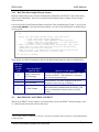
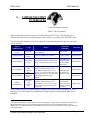
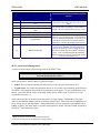
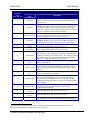
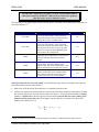
2.4.2. Online Help
The full User Interface menu structure contains full access to all parts of the configuration. To aid in
understanding specific menu options or menu items contained in the User Interface, several contextsensitive on-line help commands are available in all User Interface menus:
H
Provides general help information.
Hx
Provides information about menu item x, where x is a letter. for example, type HC to obtain
information about menu option C.
Hn
Provides information about line item n, where n is a number. for example, type H2 to obtain
information about Line Item #2. This command is only available within menus involving line items; for
example, it is available within the Communications Menu, but not within the User Menu.
HPn Provides information about PROCESS Record #n, where n is the Process Record number. This
command is available in any User Interface menu. Processes defined in the Process Menu are numbered.
Process Record #1 is the first process in the configuration, Process Record #2 is the second process in the
configuration and so on.
HPTn.m
Provides information about specific PROCESS TYPE type m, in process category n;
where m is a number designating the process category and n is the number designating the process type
within the category. This command is available within any User Interface menu.
HSn Provides information about SENSOR Record #n, where n is the Sensor Record number. This
command is available in any User Interface menu. Sensors defined in the Sensor Menu are numbered.
Coastal Environmental Systems (206) 682-6048
Page 11
ZENO®-3200
USER MANUAL
Sensor Record #1 is the first sensor in the configuration, Sensor Record #2 is the second sensor in the
configuration and so on.
HSTn Provides information about specific SENSOR TYPE number n, where n is a number designating
the sensor type. This command is available within any User Interface menu.
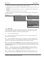
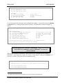
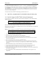
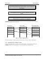
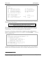
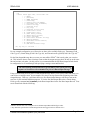
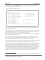
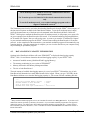
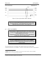
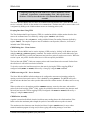
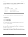
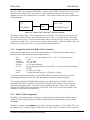
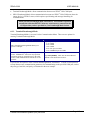
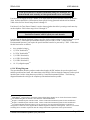
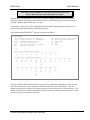
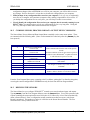
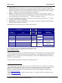
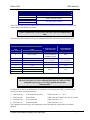
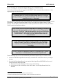
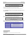
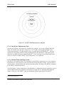
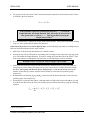
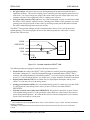
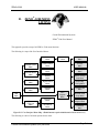
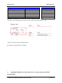
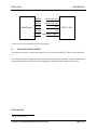
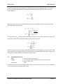
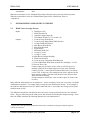
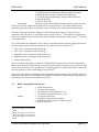
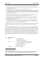
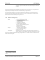
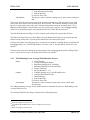
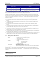
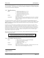
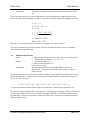
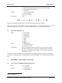
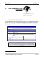
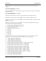
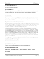
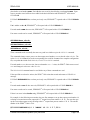
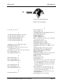
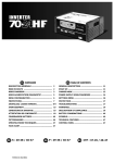
ZENO®-3200 FUNCTIONAL BLOCK DIAGRAM
2.5.
18 bit A/D
Digital I/O
One of the best ways to understand the complete functionality of the ZENO®-3200 Functional Block
Diagram is through illustration.
Multiplexer
Attenuator
1,2,4,10
Gain
1,10,100
Digital I/O
Watchdog
Timer
12 bit A/D
18 bit A/D
converter
Operating
System
32 bit CPU
12 bit A/D
converter
Serial Data
Ports
Reference
Voltage
Serial
Multiplexer
4 2
Line Drivers
(0,0.625,1.25, or 2.50v)
RS232, RS485, TTL
Com1
Line Drivers
Line Drivers
RS232, TTL
PTT
Tx Audio
Rx Audio
Switched
Power
Radio Modem
Expansion
Bus
Battery
D/A (w/ 4-20mA), A/D exp,
RWIS, Flash Logging Memory
Line Drivers
(0,1.25,2.50, or 5.00v)
Com3
Configuration
Eeprom
Logging
Memory
RS232, RS422/485
Com2
Real Time
Clock
12v 5v
Figure 2-4. ZENO®-3200 Functional Block Diagram.
(This ZENO®-3200 functional block diagram should be referred to throughout this document.)
Coastal Environmental Systems (206) 682-6048
Page 12
ZENO®-3200
USER MANUAL
3. TUTORIAL: BASIC
ZENO®-3200 OPERATION
Coastal Environmental Systems
ZENO®-3200 User Manual
This tutorial is divided into two parts:
Part One – Describes how to work with an existing configuration.
1. Viewing logged data from a simple configuration
2. Changing output message format
3. Understanding & changing the Sample Interval and power usage
Part Two – Describes the basics of how to configure the ZENO®-3200.
1. Identify what needs to be done and how the ZENO®-3200 can make it happen
2. Where to begin configuring
3. How to setup two sensors that collect data from the internal temperature and input power voltage
sensors
4. How you might process the collected data
5. How you might log the collected & processed data in logging memory
3.1.
PART ONE—HOW TO WORK WITH AN EXISTING CONFIGURATION
3.1.1. Looking At Logged Data
Let's assume that you purchased your ZENO®-3200 with a very simple, factory-installed configuration
that causes the ZENO®-3200 to perform the following:
•
There are 2 sensors. One monitors internal temperature, the other monitors input battery voltage to
the ZENO®-3200. Each of these sensors is read once per second.
•
There are 2 processes. One process calculates the average of all the internal temperature readings
done during the sample duration. The second does a similar average, but with battery voltage
readings.
•
Each data record contains the following information: the time when the data record was logged, the
average internal temperature over the sample duration and the average input battery voltage over the
sample duration.
•
The ZENO®-3200 is set to collect and process data for a duration of 55 seconds (the sample duration),
and the data collection process is to be repeated every 60 seconds (the sample interval).
•
Further, the ZENO®-3200 is set to automatically output each logged data record at the end of each
sample duration.
Coastal Environmental Systems (206) 682-6048
Page 13
ZENO®-3200
USER MANUAL
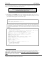
After you connect your ZENO®-3200 to your computer and apply power (as described in Section ), you
will see the start-up message on your terminal emulation program, followed by a set of measurements
generated once a minute. The screen will look something like this:
Watchdog Reset
Please wait.../
ZENO-3200 using ZENOSOFT V1.964 Jun 28 2001 15:41:01 CS 96CC
(C)opyright 1995-2001, Coastal Environmental Systems, Seattle, WA, USA.
System Time = 01/07/11 13:47:31
Initializing Zeno 3200 .../
Zeno 3200 is Data Sampling. Type 'U'{ENTER} to access the User Interface.
01/07/11,13:48:55,22.7,13.8,
01/07/11,13:49:55,22.9,13.8,
01/07/11,13:50:55,23.0,13.8,
01/07/11,13:51:55,23.2,13.8,
Each data message contains the following comma delimited fields:
•
The date and time when the measurement was completed, usually called the timestamp (here, the
afternoon of July 11, 2001).
•
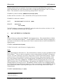
Two data values: the average internal temperature and average battery voltage.14
As this example shows, the ZENO®-3200 can output data messages giving measured data values in real
time as well as log the data. Up to four different messages can be defined, each containing different
values, outputted at different times and routed to different ZENO®-3200 COM ports.
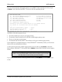
In our example, the ZENO®-3200 is outputting the data messages on COM3. If you enter the User
Interface via COM3, any real time data messages routed to COM3 will be interrupted; but messages to
other COM ports (if any) as well as data logging will not be affected.
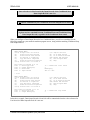
The ZENO®-3200 continues to log data records in real time while you view
data records via the User Menus.
(If you enter the Zeno Program Menus, the ZENO®-3200 will suspend all
data collection and logging.)
To view the logged data records, you first need to enter the User Menu of the ZENO®-3200 User
Interface.
To enter the User Menu, type U followed by the {ENTER} key in your
terminal emulation program.
Upon entering the User Menu, the ZENO®-3200 will stop sending real-time data messages to your
terminal emulation program and, instead, it will display the User Menu. Your screen will look something
like this.
14
Since many ZENO®-3200s are factory-configured by Coastal Environmental Systems prior to delivery, the
messages sent to your terminal emulation program are likely to differ in the number, type, and format of the
measured values.
Coastal Environmental Systems (206) 682-6048
Page 14
ZENO®-3200
USER MANUAL
01/07/11,14:13:55,23.7,13.8,
01/07/11,14:14:55,23.7,13.8,
01/07/11,14:15:55,23.7,13.8,
USER MENU
(C) Communications Menu
(F) System Functions Menu
(S) Sample Period Menu
(D) Data Retrieval Menu
>
(T)
(Z)
(Q)
(H)
Test Menu
Zeno Program Menu
Quit
Help
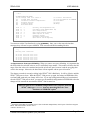
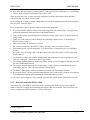
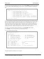
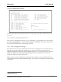
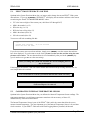
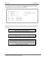
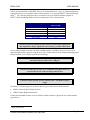
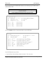
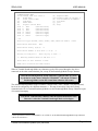
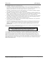
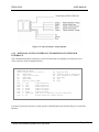
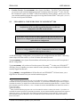
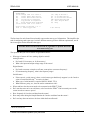
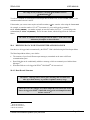
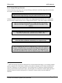
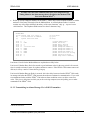
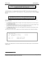
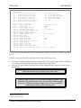
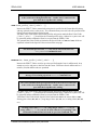
To view the logged data, you need to enter the Data Retrieval Menu. Type D, followed by the {ENTER}
or {Return} key, to bring up the Data Retrieval Menu.15 The Data Retrieval Menu will appear as
follows:
> d
DATA
(A)
(B)
(Ln)
(*)
(@n)
(M)
(C)
RETRIEVAL MENU
Show Records AFTER Specified Time
Show Records BETWEEN Timespan
Show LAST n Records
Show ALL Data Records
Show n Unmarked Records
Mark Recently Shown Data
Compute Data Logging Capacity
(F)
(D)
(N)
(U)
(Q)
(H)
Flash Memory Information
Delete All Data Records
Number of Records Logged
User Menu
Quit
Help
Precede Any "Show Data" Command With An 'X' for X-Modem Transfer
(e.g. Enter 'X*' To Send All Data Sets Via X-Modem)
>
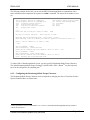
When navigating the User Interface, you must type {ENTER} or <RETURN>
at the end of every command in order for ZENOSOFT® to execute the
desired command.
While in the User Menus, if the ZENO®-3200 does not receive a command after 60 seconds,
ZENOSOFT® will automatically exit the User Interface. If this happens, simply type U{ENTER} to reenter the User Menu. The screen will look something like this:
>
WARNING: Timeout on command line input. Exiting user interface!
01/07/11,14:24:55,23.9,13.8,
01/07/11,14:25:55,23.8,13.8,
01/07/11,14:26:55,23.8,13.8,
15
Navigation of the menus in the User Interface is not case sensitive: d will also work.
Coastal Environmental Systems (206) 682-6048
Page 15
ZENO®-3200
USER MANUAL
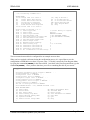
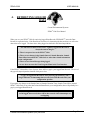
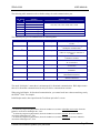
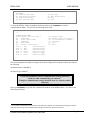
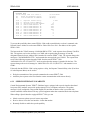
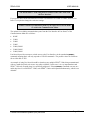
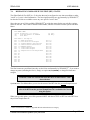
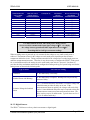
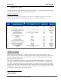
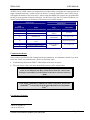
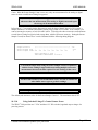
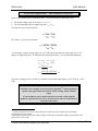
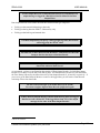
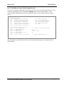
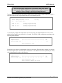
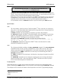
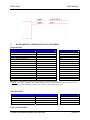
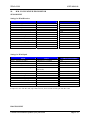
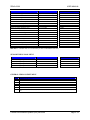
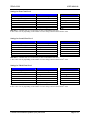
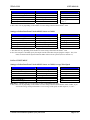
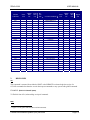
If you are curious about the data logging capacity of your ZENO®-3200, it will tell you when you type
C{ENTER} in the Data Retrieval Menu. Your screen will look something like this:
DATA
(A)
(B)
(Ln)
(*)
(@n)
(M)
(C)
RETRIEVAL MENU
Show Records AFTER Specified Time
Show Records BETWEEN Timespan
Show LAST n Records
Show ALL Data Records
Show n Unmarked Records
Mark Recently Shown Data
Compute Data Logging Capacity
(F)
(D)
(N)
(U)
(Q)
(H)
Flash Memory Information
Delete All Data Records
Number of Records Logged
User Menu
Quit
Help
Precede Any "Show Data" Command With An 'X' for X-Modem Transfer
(e.g. Enter 'X*' To Send All Data Sets Via X-Modem)
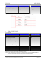
> c
Total Data Logging Memory (bytes)
Maximum Number of Data Records
Size of Each Data Record
Maximum Data Time Span (d:hh:mm:ss)
=
=
=
=
127420
15927
8
11:01:27:00
The ZENO®-3200 will accurately tell you:
•
The total available space (in bytes) for logging memory
•
The number of data records that will fit into the available logging memory space
•
The size of each data record (in bytes)
•
The maximum time that the ZENO®-3200 will take to fill up the available logging memory
Upon completion of a command internal to a menu, ZENOSOFT® automatically returns you to that same
menu, in this case the Data Retrieval Menu.
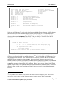
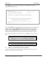
To find out how much of the available logging memory has been filled, type N{ENTER} in the Data
Retrieval Menu. ZENOSOFT® will respond with the NUMBER of data records currently stored in logging
memory.
The available logging memory is treated by ZENOSOFT® as a circular
buffer. Once the circular buffer is full, each newest data record overwrites
the oldest data record currently stored in the buffer.
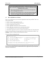
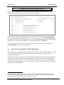
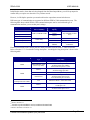
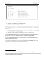
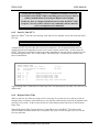
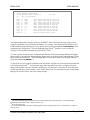
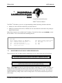
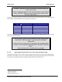
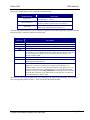
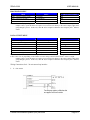
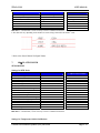
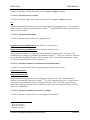
If you want to view the 4 most recently logged data records, type L4{ENTER} to see the LAST 4 data
records.
Coastal Environmental Systems (206) 682-6048
Page 16
ZENO®-3200
DATA
(A)
(B)
(Ln)
(*)
(@n)
(M)
(C)
RETRIEVAL MENU
Show Records AFTER Specified Time
Show Records BETWEEN Timespan
Show LAST n Records
Show ALL Data Records
Show n Unmarked Records
Mark Recently Shown Data
Compute Data Logging Capacity
USER MANUAL
(F)
(D)
(N)
(U)
(Q)
(H)
Flash Memory Information
Delete All Data Records
Number of Records Logged
User Menu
Quit
Help
Precede Any "Show Data" Command With An 'X' for X-Modem Transfer
(e.g. Enter 'X*' To Send All Data Sets Via X-Modem)
> L4
Hit The Space Bar To Halt The Log Data Output.
DATE
TIME
AvgTemp AvgBatt
01/07/11 15:02:55 24.1 13.8
01/07/11 15:03:55 24.2 13.8
01/07/11 15:04:55 24.2 13.8
01/07/11 15:05:55 24.1 13.8
When you are done looking at the logged data, you can quit the User Interface by typing Q{ENTER} to
QUIT (exit).
Section 4 provides comprehensive information about viewing logged Data Records.
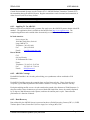
3.1.2. Changing Output Message Format
If your computer is not connected to the ZENO®-3200, connect your ZENO®-3200 to your computer and
apply power.16 After you see the boot-up message from the ZENO®-3200, type U{ENTER} in your
terminal emulation program to obtain the User Menu.
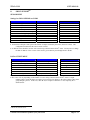
There are three types of message formats available from the ZENO®-3200:
•
Comma delimited
•
Space delimited
•
CCSAIL format (comma delimited with CCSAIL addressing)17
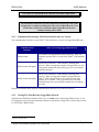
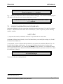
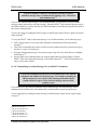
If you want to change the format of a message, you can do so with absolutely no disruption in ZENO®3200 data collection. From the User Menu, type the command F{ENTER} to enter the System Functions
Menu. You will see the following screen.
16
17
Refer to Section 2.2.
Details about the CCSAIL protocol are discussed in Section 4.6.
Coastal Environmental Systems (206) 682-6048
Page 17
ZENO®-3200
USER MANUAL
> f
SYSTEM
(Cn/m)
(S)
(T)
(V)
(K)
(B)
Item
Item
Item
Item
Item
Item
Item
Item
>
FUNCTIONS MENU
Change Item n To Value m
System Date and Time
Calibrate Internal Temperature
Program Version
Constants Menu
BIT Names Menu
1:
2:
3:
4:
5:
6:
7:
8:
0
0
1
1
0
0
0
(I)
(E)
(U)
(Q)
(H)
Contact Information
Save Parameters To EEPROM
User Menu
Quit
Help
(Primary Unit/Experiment ID)
(Secondary Unit/Experiment ID)
(Data Dump Format)
(Real Time Output Format)
(Add Compass To Vane)
(Compass Offset)
(Barometer Elevation)
(Bad Sensor Value Replace)
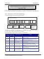
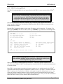
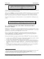
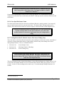
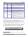
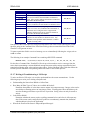
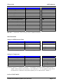
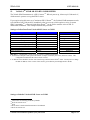
Let's say that your ZENO®-3200 is running the same simple configuration as described in the previous
subsection. In that subsection, the real-time data messages are comma delimited. The above screen shot
is from the same configuration. Line Item #4 in the System Functions Menu sets the real-time message
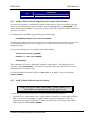
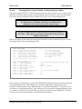
format.18 To understand what the code of "1" means, type Η4{ENTER} to get help on this specific item.
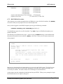
This is what your screen should look like:
> h4
* Select real time output message format, valid options are
- 0 (real time output message suppressed).
- 1 (ASCII characters, width dependent, comma separated).
- 2 (ASCII characters, [see NOTE below], no comma separation).
- 3 (CCSAIL format, [see NOTE below]).
* NOTE: for option 2, width is specified by 'Field Width' item in Data
Output Menu; if a data item uses fewer characters than specified,
leading space characters are inserted.
* NOTE: for option 3, ID numbers are 4 character fixed fields and the
checksum becomes modulo 100 with no trailing comma.
Hit any key to continue . . .
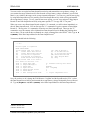
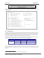
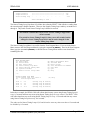
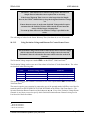
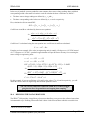
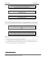
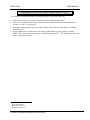
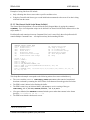
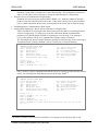
If you want to change the real-time message format to be space delimited, use the Cn/m menu option by
typing C4/2{ENTER}. When you have finished typing, ZENOSOFT® will redisplay the System
Functions Menu, but the value for Item 4 will be set to 2. Your screen should look like this:
18
Complete information about this Line Item is provided in Section 4.4.2.
Coastal Environmental Systems (206) 682-6048
Page 18
ZENO®-3200
USER MANUAL
> c4/2
SYSTEM
(Cn/m)
(S)
(T)
(V)
(K)
(B)
Item
Item
Item
Item
Item
Item
Item
Item
>
FUNCTIONS MENU
Change Item n To Value m
System Date and Time
Calibrate Internal Temperature
Program Version
Constants Menu
BIT Names Menu
1:
2:
3:
4:
5:
6:
7:
8:
0
0
1
2
0
0
0
(I)
(E)
(U)
(Q)
(H)
Contact Information
Save Parameters To EEPROM
User Menu
Quit
Help
(Primary Unit/Experiment ID)
(Secondary Unit/Experiment ID)
(Data Dump Format)
(Real Time Output Format)
(Add Compass To Vane)
(Compass Offset)
(Barometer Elevation)
(Bad Sensor Value Replace)
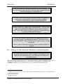
You can now exit the User Interface by typing Q{ENTER}. Once you see the next real-time data
messages, they will now be space delimited. Your screen should look something like this:
> q
Exiting user interface.
01/07/12
01/07/12
01/07/12
01/07/12
01/07/12
10:01:55
10:02:55
10:03:55
10:04:55
10:05:55
22.8
22.8
22.8
22.8
22.8
13.8
13.8
13.8
13.8
13.8
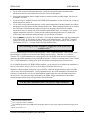
An important note about space delimiting: When you want to use space delimiting, it is important that
the field widths for each data value are set to a sufficiently large number. This number will allow the full
range of the data value to be contained and provide at least one space between it and the preceding data
value in the message. Otherwise, the data values will run together with no space in between.19
The change you made is currently residing in the ZENO®-3200’s RAM only. It will be effective until the
ZENO®-3200 powers down. When the ZENO®-3200 powers up again, the settings in EEPROM will be
read into RAM again and your change will be lost. If you want configuration changes to be maintained
after the ZENO®-3200 powers down, you must save the modified configuration into EEPROM so that the
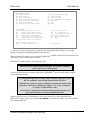
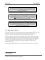
changes will be restored the next time the ZENO®-3200 is turned on.
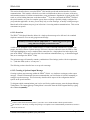
When you want to save a modified configuration in case you power down the
ZENO®-3200, type E{ENTER} from any menu that offers the "Save
Parameters to EEPROM" option.20
19
Setting the field widths for each data value is done in the Data Output Menu, which is part of the Zeno Program
Menu. This is discussed in Section 10.6.6.
20
Refer to Section 2.3.2.
Coastal Environmental Systems (206) 682-6048
Page 19
ZENO®-3200
USER MANUAL
3.1.3. Understanding & Changing the Sample Interval and Power Usage
One of the most important aspects to understand about the ZENO®-3200 is timing. All data collection
done by the ZENO®-3200 is based upon regular timed intervals that are controlled by the ZENO®-3200's
internal clock. The main timed interval is called the Sample Interval.
The Sample Interval defines the overall, recurring period of time that all
data collection, processing, data logging and transmitting occurs.
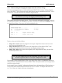
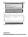
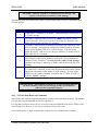
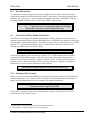
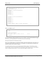
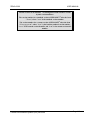
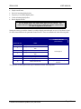
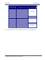
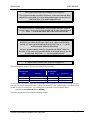
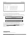
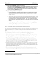
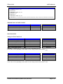
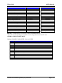
Three timing values define the Sample Interval. They are located in the Sample Period Menu. Access to
the Sample Period Menu is done through the User Menu. From the User Menu, type S{ENTER} to enter
the Sample Period Menu. Your screen will look something like this:
> s
SAMPLE
(Cn/m)
(E)
(U)
Item
Item
Item
PERIOD MENU
Change Item n To Value m
Save Parameters To EEPROM
User Menu
1:
2:
3:
60
55
0
(Q) Quit
(H) Help
(Sample Interval Time)
(Sample Duration Time)
(Sample Time Offset)
>
The three values are defined as follows:
•
Sample Interval Time defines the length of each complete Sample Interval (the time between the
start of successive Sample Intervals)
•
Sample Duration Time defines the portion of the Sample Interval Time that the ZENO®-3200
actually performs all data collection, processing, data logging and transmitting
•
Sample Time Offset defines a time at the beginning of the Sample Interval to delay the start of the
actual Sample Duration Time
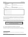
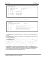
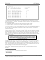
The sum of the Sample Duration Time and Sample Time Offset can be the
less than or equal to, but never exceed, the Sample Interval Time.
If you attempt to set the Sample Duration Time or the Sample Time Offset or a combination thereof to a
value greater than the Sample Interval Time, the ZENO®-3200 will respond with an error message and not
accept the requested change.
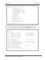
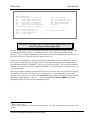
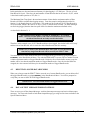
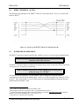
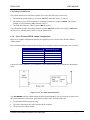
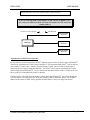
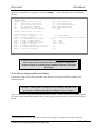
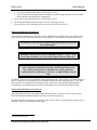
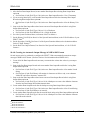
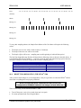
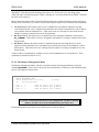
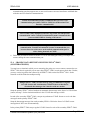
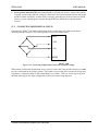
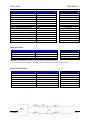
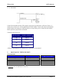
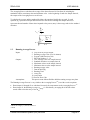
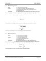
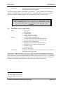
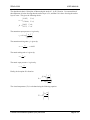
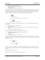
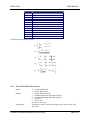
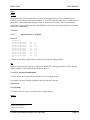
In our example "factory-installed" configuration illustrated above, the Sample Interval Time has been set
to 60 seconds and the Sample Duration Time has been set to 55 seconds. No Sample Time Offset is in
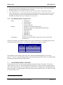
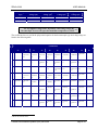
use. This is illustrated using the following timing diagram:
Coastal Environmental Systems (206) 682-6048
Page 20
ZENO®-3200
USER MANUAL
Sample Interval
Sample Duration
|---------------------------------------|
|-------------------------------------| |
60 seconds
55 seconds
Physically, when the ZENO®-3200 is collecting data, ZENOSOFT® turns on various internal components
in order to read data from the various sensors. Hence, the Sample Duration not only represents the time
when data is being collected, but also the time when the ZENO®-3200 is consuming more power. for this
reason, the Sample Duration is often referred to being the time when the ZENO®-3200 is "awake."
When the sum of the Sample Duration Time and Sample Time Offset is less than the Sample Interval
Time, there will be a time period in which the ZENO®-3200 is not performing any of its primary data
collection functions. When the ZENO®-3200 is not performing any of its primary data collection
functions, ZENOSOFT® turns off any unnecessary internal components to conserve power. This
scheduled gap in data collection is often referred to as the time when the ZENO®-3200 is "asleep."
The ZENO®-3200 consumes more power when it is collecting data.
Reducing the Sample Duration Time with respect to the Sample Interval
Time conserves power. This may be very important if the primary source of
power for your ZENO®-3200 is a battery.
Versatility is one of the essential features designed into the ZENO®-3200. The settings for the Sample
Interval Time, Sample Duration Time and Sample Offset Time will create a wide variety of possible data
collection scenarios. Power consumption may play a key role in determining your data collection
requirements.
Here are three examples that will demonstrate very different ways that you can set up the ZENO®-3200
data collection cycle:
ZENO®-3200
Parameter
Example A
Sample sensors
continuously (no sleep
time), log data once an
hour.
Example B
Sample sensors for one
minute, once per hour;
log data once an hour.
Example C
Sample sensors during
regular business hours
every 24 hours, log data
once a day.
Sample Interval
Time
1 hour
(3600 seconds)
1 hour
(3600 seconds)
24 hours
(86400 seconds)
Sample Duration
Time
1 hour
(3600 seconds)
1 minute
(60 seconds)
10 hours
(36000 seconds)
Sample Offset
Time
0 seconds
0 seconds
9 hours (start at 8 a.m.)
(32400 seconds)
In the following time line, the darkened areas illustrate when the ZENO®-3200 is awake and sensors are
being sampled for these three examples over a 24-hour period.
Coastal Environmental Systems (206) 682-6048
Page 21
ZENO®-3200
Hour
of the
Day
0
1
USER MANUAL
2
3
4
5
6
7
8
9
10 11 12 13 14 15 16 17 18 19 20 21 22 23
A.
B.
C.
The Sample Interval nearly always begins at a time that is divisible by the Sample Interval Time, whose
modulus is zero. Here are some examples:
•
If the Sample Interval Time is set to on hour (3600 seconds), each Sample Interval will begin on the
hour.
•
If the Sample Interval Time is set to fifteen minutes (900 seconds), each Sample Interval will begin
on the quarter hour.
•
If the Sample Interval Time is set to 30 seconds, each Sample Interval will begin on every half
minute.
In our example configuration, if you want the ZENO®-3200 to conserve more power, you could set the
Sample Duration Time to 10 seconds by typing C2/10{ENTER} in the Sample Period Menu. If you
want the ZENO®-3200 to collect data toward the end of the Sample Interval, you can set the Sample Time
Offset to 50 by typing C3/50{ENTER} also in the Sample Period Menu. You would get the following
timing result:
Sample Interval
|---------------------------------------| 60 seconds
Sample Duration
|
|----| 10 seconds
Sample Time Offset |----------------------------------|
| 50 seconds
When you change one of the Sample Interval parameters in the Sample
Period Menu, ZENO®-3200 will stop all data collection until the first newly
modified Sample Interval is scheduled to begin.
You can experiment with various values for the Sample Interval Time, the Sample Duration Time, and the
Sample Time Offset. You can check the results of your changes by:
•
Quitting the User Interface (typing Q{ENTER}), and watching the messages written from COM3 to
your terminal emulation program in real time;
Coastal Environmental Systems (206) 682-6048
Page 22
ZENO®-3200
•
USER MANUAL
Going to the Data Retrieval Menu (type U{ENTER} D{ENTER}), and looking at the logged data.
It is important to remember that as long as you don't save your configuration changes to EEPROM (by
typing E{ENTER}), you can always retrieve the original configuration by powering down your ZENO®3200. When it powers up, the original configuration stored in EEPROM will be copied into RAM and
become the working configuration.
An extensive discussion of ZENO®-3200 timing is provided in Section 12.1.
3.2.
PART TWO—LEARNING HOW TO CONFIGURE YOUR OWN ZENO®-3200
3.2.1. How Do I Configure The ZENO®-3200 To Perform My Requirements?
If you purchased your ZENO®-3200 with no factory-installed configuration, it will be shipped with the
default configuration.
The default ZENO®-3200 configuration contains no sensors, no processes
and no data to be logged. It is a blank configuration.
In this case, you need to configure the ZENO®-3200 to meet your own requirements.
In this section, some simple aspects of configuring sensors, processes and setting up data to be logged and
transmitted will be examined.
Before you start to configure your own ZENO®-3200, ask yourself the following list of questions.
Identifying what you need the ZENO®-3200 to do and how the ZENO®-3200
can accomplish your requirements will simplify the configuration process.
1.
2.
3.
4.
5.
6.
7.
8.
9.
10.
11.
What do I need to the ZENO®-3200 to measure?
What are the types of sensors that I need to collect data from?
How do my sensors match each of the sensor types defined in ZENOSOFT®?
How often do I need to measure data from each sensor (once every second, twice every 5 seconds,
once every 10 seconds, etc.)
How do I electrically connect each sensor to the ZENO®-3200?
Do I need each sensor to be powered continuously or do I want each sensor powered only when a
measurement is to be taken? (This may be very important if your ZENO®-3200 has a limited source
of power.)
Do I need data that can only be obtained indirectly by processing the collected data?
If processing is required, which process (or processes) can I use to obtain the desired results?
Which collected and processed data (if any) needs to be logged in each data record?
Which collected and processed data (if any) needs to be transmitted? (Is it the same or different from
the data that is to be logged?)
Do I need the ZENO®-3200 to transmit the data records automatically or do I only plan to view
logged data?
Coastal Environmental Systems (206) 682-6048
Page 23
ZENO®-3200
USER MANUAL
12. How much and how often do I want the ZENO®-3200 to perform the configuration; i.e., what Sample
Interval, Sample Duration and Sample Offset will be used?
Other questions may arise, or some may not be important; but each of the listed questions should be
answered so that "no stone is left uncovered."
For an illustration of creating a simple configuration, let's use the configuration that was used throughout
Part One of the Tutorial Section.21
First, we must answer the 12 questions asked in the preceding paragraphs:
1. We need the ZENO®-3200 to measure its internal temperature and battery voltage, average the data,
and log and transmit the data at the end of each Sample Interval.
2. There are two sensors: internal temperature and battery voltage. Each sensor is an internal (built-in)
analog sensor.
3. In this case, each sensor is a built-in analog sensor internally connected to the 12-bit Analog-toDigital Converter (ADC).
4. Each sensor needs to be read once per second.
5. No external connections to the ZENO®-3200 are necessary since each sensor is built-in.
6. Each internal sensor is powered internally. It is not necessary to control the power to each built-in
sensor.
7. We need to view the average value of all the readings taken from each sensor over the course of the
Sample Interval.
8. To obtain the average value of all the readings taken from each sensor, two Average Processes will
need to be configured. (One Average Process per sensor.)
9. The average internal temperature and average battery voltage need to be logged in each data record at
the end of each Sample Interval.
10. The average internal temperature and average battery voltage need to be transmitted at the end of
each Sample Interval. This is the same data that is being logged.
11. The ZENO®-3200 needs to transmit each data record at the end of the Sample Duration.
12. We need the ZENO®-3200 to perform all data collection once a minute and to measure the sensors for
55 seconds before logging and transmitting the collected and processed data.
As you can see, answering those 12 key questions will make the creation of this configuration very easy.
3.2.2. Data Flow within the ZENO®-3200
The general flow of the ZENO®-3200 begins with 1) collecting data from sensor, 2) processing the
collected data, and 3) logging and transmitting the collected and processed data. This is the best way to
create a configuration and is illustrated as a "recipe card" below:
21
Refer to Section 3.1.
Coastal Environmental Systems (206) 682-6048
Page 24
ZENO®-3200
USER MANUAL
ZENO®-3200 Configuration Recipe Card
1. Configure the sensors.
2. Configure the processes.
3. Configure the data to be logged & transmitted.
4. Set all other configuration settings.
Configuring the sensors, processes and data outputs are all done through the Zeno Program Menu.
The ZENO®-3200 does not perform any data collection, data processing or
logging & transmitting while you are in the Zeno Program Menu or any of
its submenus.
Accessing the Zeno Program Menu is done via the User Menu. If you are currently not in the User
Interface, follow the instructions in Section 2.2 to access the User Menu.
From the User Menu, type Z{ENTER} to enter the Zeno Program Menu. Your screen should look like
the following:
USER MENU
(C) Communications Menu
(F) System Functions Menu
(S) Sample Period Menu
(D) Data Retrieval Menu
(T)
(Z)
(Q)
(H)
Test Menu
Zeno Program Menu
Quit
Help
> Z
Enter Administrator Password:
Access to the Zeno Program Menu is password-protected!22
Unless your ZENO®-3200 password has been modified, the default password is "ZENO". Type
ZENO{ENTER} to gain access to the Zeno program Menu.
22
Refer to Section 8.1.
Coastal Environmental Systems (206) 682-6048
Page 25
ZENO®-3200
USER MANUAL
Enter Administrator Password: ****
Waiting for all data acquisition tasks to finish . . .
ZENO PROGRAM MENU
(S) Sensor Menu
(P) Process Menu
(D) Data Output Menu
(T) Sensor Timing Loop Menu
(O) Output Message Timing Menu
(L) System Load Menu
(G) General Serial Script Menu
(M)
(W)
(R)
(E)
(U)
(Q)
(H)
Memory Management Menu
Password Menu
Reset System
Save Parameters To EEPROM
User Menu
Quit
Help
>
Whenever you enter a password to gain access to the Zeno Program Menu,
the characters you type are not shown for security.
In this tutorial, the three submenus that will be visited in the Zeno Program Menu are 1) the Sensor Menu,
2) the Process Menu and 3) the Data Output Menu. The other submenus contained in the Zeno Program
Menu will be discussed in detail in a later section of this manual.
•
The Sensor Menu allows you to match ZENO®-3200 hardware and ZENOSOFT® firmware to your
specific sensor suite.23
•
The Process Menu allows you to specify any calculations that need to be carried out on the data
collected from the sensors.24
•
The Data Output Menu allows you to specify which data from processes and/or sensors is to be
included in the output message(s) and/or to be logged into ZENO®-3200 memory for later retrieval.25
Since it is likely that you will need to configure multiple sensors, processes, and data output fields, these
three submenus have been designed to create various lists of sensors, processes and data output fields.
Each sensor, process or data output field that is configured is referred to as
a Record. Hence, any ZENO®-3200 configuration will contain a list of one
or more Sensor Records, a list of one or more Process Records and a list of
one or more Data Output Records.
A list of records implies two things:
1. There will be a known number of records within the list; i.e., a list of "n" records, where "n" is a
number.
2. Reference to a specific record within the list will be a numerical index to that record; i.e., first record,
second record, third record . . . "nth” record.
23
Discussed in Section 3.2.3.
Discussed in Section 3.2.4.
25
Discussed in Section 3.2.5.
24
Coastal Environmental Systems (206) 682-6048
Page 26
ZENO®-3200
USER MANUAL
A Process Record can refer to any Sensor Record or any preceding Process
Record. A Process Record cannot refer to itself nor to any Process Record
proceeding it.
A Data Output Record can refer to any Process Record or any Sensor
Record.
One type of Sensor Record can refer to any Process Record+
but is used for a very special case in a configuration.
An illustration of referencing between Sensor Records, Process Records and Data Output Records in a
hypothetical configuration is shown below.
Sensor Menu
Process Menu
Data Output Menu
Sensor Record 1
Process Record 1
Data Output Record 1
Sensor Record 2
Process Record 2
Data Output Record 2
Sensor Record 3
Process Record 3
Data Output Record 3
Data Output Record 4
Data Output Record 5
Data Output Record 6
Figure 3-1. ZENO®-3200 Data Flow.*
*The arrows in Figure 3-1 show the direction of the reference. The flow of data is in the opposite.
3.2.3. Learning How To Configure A Sensor
From the Zeno Program Menu, you want to enter the Sensor Menu. To enter the Sensor Menu, type
S{ENTER} from the Zeno Program Menu. Your screen should look something like this:
Coastal Environmental Systems (206) 682-6048
Page 27
ZENO®-3200
USER MANUAL
ZENO PROGRAM MENU
(S) Sensor Menu
(P) Process Menu
(D) Data Output Menu
(T) Sensor Timing Loop Menu
(O) Output Message Timing Menu
(L) System Load Menu
(G) General Serial Script Menu
(M)
(W)
(R)
(E)
(U)
(Q)
(H)
Memory Management Menu
Password Menu
Reset System
Save Parameters To EEPROM
User Menu
Quit
Help
> S
SENSOR
(Cn/m)
(A)
(B)
(X)
(C)
(V)
(Sn/m)
MENU
Change Item n To Value m
Insert After This Record
Insert Before This Record
Cut Record to Clipboard
Copy Record To Clipboard
Paste Record From Clipboard
Search Item n for Value m
Sensor Items for Record 1 of 1:
Item 1: Sensor Type Code
(Jn)
(N)
(P)
(XA)
(Z)
(H)
Jump To Record n
Go To Next Record
Go To Previous Record
Delete ALL Records
Zeno Program Menu
Help
0 (No Sensor)
>
As you can see, there are many options available in the Sensor Menu that will help you to navigate
through a configuration containing multiple Sensor Records.
When no Sensor Records have been configured, ZENOSOFT® defines a default of one Sensor Record of
Sensor Type Code 0, which means “no sensor.”
ZENOSOFT® contains a library of Sensor Type Codes.
Each type of sensor supported by ZENOSOFT® has a unique, numerical
Sensor Type Code for identification.
The three general categories of sensors supported by ZENOSOFT® include Analog Sensors, Digital
Sensors and Serial Sensors:
An Analog Sensor generates a voltage within a specified range (0 to 5 volts
DC, for example) to represent the measurement it has taken.
A Digital Sensor generates a binary condition to represent the measurement
it has taken. The binary condition may simply be "on or off," a frequency,
or a binary-encoded numeric value.
A Serial Sensor communicates its measured data (possibly more than one
type of measurement) via a serial communications link.
Whenever you want to view a summarized version of all Sensor Type Codes supported by the
ZENOSOFT® library, just type the command H1{ENTER} from the Sensor Menu. Your screen should
look something like this:
Coastal Environmental Systems (206) 682-6048
Page 28
ZENO®-3200
USER MANUAL
> H1
* Select Sensor Type Code, valid codes are
- 0 (No Sensor)
- 1 (12-bit Analog to Digital)
- 2 (18-bit Single-Ended A to D)
- 3 (18-bit Differential A to D)
- 4 (Digital Period, f > 10 KHz)
- 5 (Digital Frequency, f > 10 KHz)
- 6 (Digital Period, f < 10 KHz)
- 7 (Digital Frequency, f < 10 KHz)
- 8 (Digital State)
- 9 (Digital Edge)
- 10 (Tipping Bucket)
- 11 (Serial Compass)
- 12 (CCSAIL)
- 13 (SDI-12 Serial)
- 14 (Differential Encoder)
- 15 (GPS Receiver)
- 16 (General Serial)
- 17 (Continuous SDI-12 Serial)
- 18 (Concurrent SDI-12 Serial)
- 19 (Asynchronous CCSAIL)
Hit any key to continue . . .
Our example configuration will use the Internal Temperature Sensor, which is available as a 12-bit ADC
sensor, a Sensor Type Code of 1. So, to configure a 12-bit ADC sensor type for the current Sensor
Record (in this case, Sensor Record #1), type the command C1/1{ENTER} in the Sensor Menu. Once
this is done, the number of line items listed will drastically change, as illustrated below:
> C1/1
SENSOR
(Cn/m)
(A)
(B)
(X)
(C)
(V)
(Sn/m)
MENU
Change Item n To Value m
Insert After This Record
Insert Before This Record
Cut Record to Clipboard
Copy Record To Clipboard
Paste Record From Clipboard
Search Item n for Value m
Sensor Items for Record 1 of 1:
Item 1: Sensor Type Code
Item 2: Sensor Name
Item 3: Sensor Input Channel
Item 6: Switched Power Code
Item 7: Sensor Excitation Voltage Code
Item 8: Switched Excitation Return
Item 9: Switched Power Warmup Time
Item 10: Sensor Sample Count
Item 11: Maximum Sensor Readings
Item 12: Sensor Timing Loop
Item 13: Conversion Coefficient A
Item 14: Conversion Coefficient B
Item 15: Conversion Coefficient C
Item 17: No. of Additional 15-msec Delays
(Jn)
(N)
(P)
(XA)
(Z)
(H)
Jump To Record n
Go To Next Record
Go To Previous Record
Delete ALL Records
Zeno Program Menu
Help
1 (12-bit Analog to Digital)
8
0 (NO SWITCHED POWER)
0 (NO EXCITATION VOLTAGE)
0
0
1
0
1 (0.5 seconds)
0
1
0
0
>
Coastal Environmental Systems (206) 682-6048
Page 29
ZENO®-3200
USER MANUAL
As you can see, the value for Line Item #1 (the Sensor Type Code) has been set to a 12-bit ADC sensor.
The other Line Items that have appeared are the relevant fields that can be set for a 12-bit ADC sensor
that tell ZENOSOFT® how to collect data from the sensor.
The library that ZENOSOFT® maintains about each Sensor Type includes
the specific Line Items that fully define the complete Sensor Type
Definition.26
The Line Item numbers that fully describe a complete Sensor Type
Definition are always in the same location for any Sensor Type Code.
The second Line Item is the Sensor Name. The Sensor Name is an optional field that allows you to write
up to an 8-character name to uniquely identify a particular Sensor Record.27
Sensor Names are extremely useful because when a configuration has many
Sensor Records with the same Sensor Type Code, they will help you
remember which Sensor Record is collecting data from which sensor.
As an example, you want to collect data from four 18-bit ADC single-ended sensors. The four sensors
measure wind speed, wind direction, temperature and humidity. The four Sensor Records that define
these four sensors are numbered one (1) through four (4). What happens if you do not look at the
configuration for a long period of time? How can you remember which Sensor Record collects which
sensor data? You can use the Sensor Record number as identification, or you can assign sensor names
such as "WS," "WD," "Temp," and "Humid" for the four Sensor Records. Most people will probably find
it much easier to differentiate Sensor Records if they assign unique sensor names.
In our example configuration, Sensor Record #1 is going to measure data from the Internal Temperature
Sensor. An appropriate Sensor Name for line item #2 could be "IntTemp". If you want to set the Sensor
Name to "IntTemp", type the command C2/IntTemp{ENTER} in the Sensor Menu.28
Your screen should now look something like this:
26
Refer to Section 10.3 for the complete library of supported sensor types.
Refer to Section 10.3.6.
28
No quotation marks are used in the command.
27
Coastal Environmental Systems (206) 682-6048
Page 30
ZENO®-3200
USER MANUAL
> C2/IntTemp
SENSOR
(Cn/m)
(A)
(B)
(X)
(C)
(V)
(Sn/m)
MENU
Change Item n To Value m
Insert After This Record
Insert Before This Record
Cut Record to Clipboard
Copy Record To Clipboard
Paste Record From Clipboard
Search Item n for Value m
Sensor Items for Record 1 of 1:
Item 1: Sensor Type Code
Item 2: Sensor Name
Item 3: Sensor Input Channel
Item 6: Switched Power Code
Item 7: Sensor Excitation Voltage Code
Item 8: Switched Excitation Return
Item 9: Switched Power Warmup Time
Item 10: Sensor Sample Count
Item 11: Maximum Sensor Readings
Item 12: Sensor Timing Loop
Item 13: Conversion Coefficient A
Item 14: Conversion Coefficient B
Item 15: Conversion Coefficient C
Item 17: No. of Additional 15-msec Delays
(Jn)
(N)
(P)
(XA)
(Z)
(H)
Jump To Record n
Go To Next Record
Go To Previous Record
Delete ALL Records
Zeno Program Menu
Help
1 (12-bit Analog to Digital)
IntTemp
8
0 (NO SWITCHED POWER)
0 (NO EXCITATION VOLTAGE)
0
0
1
0
1 (0.5 seconds)
0
1
0
0
>
If you aren't sure what the valid characters are for a Sensor Name, type the help command H2{ENTER}
in the Sensor Menu and your screen should look like something like this:
> H2
* Select Sensor Name. Valid values are:
- character string up to 8 characters in length.
* NOTE: Name is optional.
* NOTE: Embedded spaces and other non-alphanumeric characters are
not allowed!. Non-alpanumeric characters MUST be entered in
hexadecimal and placed inside brackets: <xx>, where 'xx' is a
2-digit hexadecimal number (00 to FF).
Hit any key to continue . . .
Line Item #3 is a very important Line Item in the Sensor Record: the Sensor Input Channel.
The Sensor Input Channel tells ZENOSOFT® where the sensor is physically
connected to the ZENO®-3200.
Different sensor types have different physical channels located primarily on the ZENO®-3200 Front
Panel.29
29
Refer to Section 2.1.
Coastal Environmental Systems (206) 682-6048
Page 31
ZENO®-3200
USER MANUAL
No exterior physical connections are required to measure the Internal
Temperature Sensor or Battery Voltage.
To measure the Internal Temperature Sensor or the Battery Voltage, you only need to specify which one
to use in the Sensor Input Channel for the 12-bit ADC Sensor type. Type the help command for line item
#3: type H3{ENTER} in the Sensor Menu and your screen should look like something like this:
> H3
* Define 12-bit Analog to Digital Sensor Input Channel. Valid values are:
- 8, 9, BATTERY VOLTAGE, INTERNAL TEMPERATURE SENSOR, GND,
A1+ to A16+, A1- to A16-, B1+ to B16+, B1- to B16-,
C1+ to C16+, C1- to C16-, D1+ to D16+ and D1- to D16Hit any key to continue . . .
As the help information indicates for Line Item #3, the available channels for the 12-bit ADC sensor type
are channels 8, 9, BATTERY VOLTAGE, INTERNAL TEMPERATURE SENSOR and GND. The
other listed channels are only available on Analog Expansion Boards.30
When you are finished viewing any help information, typing any key in your
terminal emulation program will instruct the ZENO®-3200 to display the
previous menu. If you don't type any key, the ZENO®-3200 will
automatically return to the previous menu after 60 seconds.
To specify the Internal Temperature Sensor, it is not necessary to completely type out "INTERNAL
TEMPERATURE SENSOR" in the command. You can abbreviate it like so: type C3/INT{ENTER} in
the Sensor Menu, and your screen should look something like this:
30
If you had a single Analog Expansion Board setup for 12-bit ADC, it would be called Analog Expansion Board A
and the valid channels would be A1+ through A16+ and A1- through A16-. Up to four Analog Expansion Boards
are supported by a single ZENO®-3200, and they would be named boards A through D. Refer to Section 10.3.1 for
more information.
Coastal Environmental Systems (206) 682-6048
Page 32
ZENO®-3200
USER MANUAL
> C3/INT
SENSOR
(Cn/m)
(A)
(B)
(X)
(C)
(V)
(Sn/m)
MENU
Change Item n To Value m
Insert After This Record
Insert Before This Record
Cut Record to Clipboard
Copy Record To Clipboard
Paste Record From Clipboard
Search Item n for Value m
Sensor Items for Record 1 of 1:
Item 1: Sensor Type Code
Item 2: Sensor Name
Item 3: Sensor Input Channel
Item 6: Switched Power Code
Item 7: Sensor Excitation Voltage Code
Item 8: Switched Excitation Return
Item 9: Switched Power Warmup Time
Item 10: Sensor Sample Count
Item 11: Maximum Sensor Readings
Item 12: Sensor Timing Loop
Item 13: Conversion Coefficient A
Item 14: Conversion Coefficient B
Item 15: Conversion Coefficient C
Item 17: No. of Additional 15-msec Delays
(Jn)
(N)
(P)
(XA)
(Z)
(H)
Jump To Record n
Go To Next Record
Go To Previous Record
Delete ALL Records
Zeno Program Menu
Help
1 (12-bit Analog to Digital)
IntTemp
INTERNAL TEMPERATURE SENSOR
0 (NO SWITCHED POWER)
0 (NO EXCITATION VOLTAGE)
0
0
1
0
1 (0.5 seconds)
0
1
0
0
>
You have successfully instructed the ZENO®-3200 to collect data from the Internal Temperature Sensor
in Sensor Record #1. One more Line Item needs to be examined in the Sensor Menu: Line Item 12, the
Sensor Timing Loop. In our example, we want to collect data from the Internal Temperature Sensor once
a second.
The Sensor Timing Loop tells ZENOSOFT® how frequently to collect data
from the defined sensor over the course of the Sample Duration.
The current setting for Line Item #12, the Sensor Timing Loop, is for Timing Loop #1.
There are four available Sensor Timing Loops. Sensor Timing Loop #1 is
always a 0.5-second timing loop, but the other three can be modified using a
different menu.31
If we keep the Sensor Timing Loop set to 0.5 seconds, ZENOSOFT® will read from this sensor every
half-second instead of once per second. The default value for Sensor Timing Loop #2 is 1 second. Type
the command C12/2{ENTER} in the Sensor Menu, and your screen should look something like this:
31
Modifying Sensor Timing Loops is discussed in Section 10.3.7.
Coastal Environmental Systems (206) 682-6048
Page 33
ZENO®-3200
USER MANUAL
> C12/2
SENSOR
(Cn/m)
(A)
(B)
(X)
(C)
(V)
(Sn/m)
MENU
Change Item n To Value m
Insert After This Record
Insert Before This Record
Cut Record to Clipboard
Copy Record To Clipboard
Paste Record From Clipboard
Search Item n for Value m
Sensor Items for Record 1 of 1:
Item 1: Sensor Type Code
Item 2: Sensor Name
Item 3: Sensor Input Channel
Item 6: Switched Power Code
Item 7: Sensor Excitation Voltage Code
Item 8: Switched Excitation Return
Item 9: Switched Power Warmup Time
Item 10: Sensor Sample Count
Item 11: Maximum Sensor Readings
Item 12: Sensor Timing Loop
Item 13: Conversion Coefficient A
Item 14: Conversion Coefficient B
Item 15: Conversion Coefficient C
Item 17: No. of Additional 15-msec Delays
(Jn)
(N)
(P)
(XA)
(Z)
(H)
Jump To Record n
Go To Next Record
Go To Previous Record
Delete ALL Records
Zeno Program Menu
Help
1 (12-bit Analog to Digital)
IntTemp
INTERNAL TEMPERATURE SENSOR
0 (NO SWITCHED POWER)
0 (NO EXCITATION VOLTAGE)
0
0
1
0
2 (1.0 seconds)
0
1
0
0
>
The Sensor Type Definition for our Internal Temperature Sensor is now complete. Creation of this
Sensor Type Definition took four commands. Since the ZENO®-3200 supports multiple, space-delimited
commands being sent in a single command line, you could have sent all four commands in this single
command line in the Sensor Menu: C1/1 C2/IntTemp C3/INT C12/2{ENTER}.
One Sensor Record is now fully configured, but for our example, one more Sensor Record needs to be
configured to measure Battery Voltage.
We need to tell the ZENO®-3200 to create another Sensor Record. Two commands in the Sensor Menu
are available for this purpose: the "A" and "B" commands. The "A" command instructs ZENOSOFT® to
create a new Sensor Record AFTER the current Sensor Record. The "B" command instructs
ZENOSOFT® to create a new Sensor Record BEFORE the current Sensor Record.32
During the Sample Duration, data is collected from sensors based upon the
order of the Sensor Records and the Sensor Timing Loop assigned to each
sensor.
From our example configuration, we want the Sensor Record for Battery Voltage to come after the
Internal Temperature Sensor. To create a new Sensor Record after the current one, type the command
A{ENTER} in the Sensor Menu and the screen will look like the following:
32
This is also discussed in Section 10.2.
Coastal Environmental Systems (206) 682-6048
Page 34
ZENO®-3200
USER MANUAL
> A
SENSOR
(Cn/m)
(A)
(B)
(X)
(C)
(V)
(Sn/m)
MENU
Change Item n To Value m
Insert After This Record
Insert Before This Record
Cut Record to Clipboard
Copy Record To Clipboard
Paste Record From Clipboard
Search Item n for Value m
Sensor Items for Record 2 of 2:
Item 1: Sensor Type Code
(Jn)
(N)
(P)
(XA)
(Z)
(H)
Jump To Record n
Go To Next Record
Go To Previous Record
Delete ALL Records
Zeno Program Menu
Help
0 (No Sensor)
>
Each time a new Sensor Record is created, the default Sensor Type Code of
“0” is used.
This new Sensor Record looks the same as the first, except for the line above Line Item #1 which reads,
"Sensor Items for Record 2 of 2". There are now two Sensor Records in the configuration and you are
looking at the second Sensor Record. Notice options "N" and "P" in the Sensor Menu. Option "P" will
take you back to the first Sensor Record by typing the command P{ENTER}. If there were a third Sensor
Record, option "N" would take you to that record. The "J" command can also be used to "jump" any
Sensor Record in a configuration.
Menu options "N," "P," and "J" allow you to navigate a configuration
without making any changes to the configuration.
To create the Sensor Type Definition for Battery Voltage, we already know that the Internal Battery
Voltage sensor is a built-in 12-bit ADC sensor, like the Internal Temperature Sensor. Therefore, the same
steps used to configure the first Sensor Record can be used to configure the second:
•
The Sensor Type Code needs to be set to 1 to refer to a 12-bit ADC sensor.
•
From looking at the help for the Sensor Channel, we know that we can set the Sensor Channel to
BATTERY VOLTAGE by using the shorthand "BATT."
•
Since we are reading the Battery Voltage once a second (like the Internal Temperature Sensor), we
want to use the same Sensor Timing Loop as for the Internal Temperature Sensor.
•
We can give the Battery Voltage Sensor the name "Battery."
Therefore, we can send all the commands to read the Internal Battery Voltage Sensor by typing this
single, space-limited, multi-command line: C1/1 C2/Battery C3/BATT C12/2{ENTER}.
Upon doing so, the screen will look something like this:
Coastal Environmental Systems (206) 682-6048
Page 35
ZENO®-3200
USER MANUAL
> C1/1 C2/Battery C3/BATT C12/2
SENSOR
(Cn/m)
(A)
(B)
(X)
(C)
(V)
(Sn/m)
MENU
Change Item n To Value m
Insert After This Record
Insert Before This Record
Cut Record to Clipboard
Copy Record To Clipboard
Paste Record From Clipboard
Search Item n for Value m
(Jn)
(N)
(P)
(XA)
(Z)
(H)
Sensor Items for Record 2 of 2:
Item 1: Sensor Type Code
Item 2: Sensor Name
Item 3: Sensor Input Channel
Item 6: Switched Power Code
Item 7: Sensor Excitation Voltage Code
Item 8: Switched Excitation Return
Item 9: Switched Power Warmup Time
Item 10: Sensor Sample Count
Item 11: Maximum Sensor Readings
Item 12: Sensor Timing Loop
Item 13: Conversion Coefficient A
Item 14: Conversion Coefficient B
Item 15: Conversion Coefficient C
Item 17: No. of Additional 15-msec Delays
Jump To Record n
Go To Next Record
Go To Previous Record
Delete ALL Records
Zeno Program Menu
Help
1 (12-bit Analog to Digital)
Battery
BATTERY VOLTAGE
0 (NO SWITCHED POWER)
0 (NO EXCITATION VOLTAGE)
0
0
1
0
2 (1.0 seconds)
0
1
0
0
>
The two sensors that needed to be configured for our example are now done.
When you have reached a milestone during the configuration process, it is a good idea to save the
configuration to EEPROM in case there is a power surge. To do this, return to the Zeno Program Menu
by typing the command Z{ENTER} in the Sensor Menu. Once back in the Zeno Program Menu, type the
command E{ENTER}. Once you have done that, you will see something like this on your screen:
> e
Verifying parameters can be stored in EEPROM . . .
Saving parameters to EEPROM . . .
Saving sensor lists to EEPROM . . .
Saving process lists to EEPROM . . .
Saving data output lists to EEPROM . . .
Saving repeater lists to EEPROM . . .
Saving general serial scripts to EEPROM . . .
Saving constants to EEPROM . . .
665 out of 2048 bytes used in EEPROM.
Total EEPROM Writes = 151, EEPROM Checksum = 102.
ZENO PROGRAM MENU
(S) Sensor Menu
(P) Process Menu
(D) Data Output Menu
(T) Sensor Timing Loop Menu
(O) Output Message Timing Menu
(L) System Load Menu
(G) General Serial Script Menu
(M)
(W)
(R)
(E)
(U)
(Q)
(H)
Memory Management Menu
Password Menu
Reset System
Save Parameters To EEPROM
User Menu
Quit
Help
>
Coastal Environmental Systems (206) 682-6048
Page 36
ZENO®-3200
USER MANUAL
3.2.4. Learning How To Configure A Process
From the Zeno Program Menu, you want to enter the Process Menu. To enter the Process Menu, type
P{ENTER} from the Zeno Program Menu.
Your screen should look something like this:
ZENO PROGRAM MENU
(S) Sensor Menu
(P) Process Menu
(D) Data Output Menu
(T) Sensor Timing Loop Menu
(O) Output Message Timing Menu
(L) System Load Menu
(G) General Serial Script Menu
(M)
(W)
(R)
(E)
(U)
(Q)
(H)
Memory Management Menu
Password Menu
Reset System
Save Parameters To EEPROM
User Menu
Quit
Help
> P
PROCESS MENU
(Cn/m) Change Item n To Value m
(A)
Insert After This Record
(B)
Insert Before This Record
(X)
Cut Record to Clipboard
(C)
Copy Record To Clipboard
(V)
Paste Record From Clipboard
(Sn/m) Search Item n for Value m
Process Items for Record 1 of 1:
Item 1: Process Category
Item 2: Process Number
Item 3: User-defined Process Name
Item 4: Input for Immediate Data
(Jn)
(N)
(P)
(XA)
(Z)
(H)
1
1
Jump To Record n
Go To Next Record
Go To Previous Record
Delete ALL Records
Zeno Program Menu
Help
: General
: Immediate Data Process
S0.1
>
The Process Menu options should look very familiar because they are same set of menu options used in
the Sensor Menu.33 When you proceed to the next section about the Data Output Menu, you will find the
same menu options also. The reason is simple: Sensor Records, Process Records and Data Output
Records are each a list of records. Navigation through each list is identical, but the content of each list
differs.
Similar to when no Sensor Records have been configured, when no Process Records have been
configured, the default is one Process Record that is set to an Immediate Data Process.
The number of available types of processes contained in ZENOSOFT® far exceeds the number of types of
sensors. Since there are so many available processes, it is easier to group similar processes into
categories.
Each process type is identified by a numerical Process Category and a
numerical Process Number within the Process Category.34
33
34
Refer to Sections 3.2.3 and 10.2.
Refer to Section 10.4.1.
Coastal Environmental Systems (206) 682-6048
Page 37
ZENO®-3200
USER MANUAL
To aid in identifying the type of process desired, each numerical Process Category is named to identify
the grouping of process types that it contains. All basic versions of ZENOSOFT® contain six Process
Categories.35
The names of the six Process Categories are listed below:
1.
2.
3.
4.
5.
6.
General Processes Category
Environmental Processes Category
Alarm Processes Category
Special Sensor Processes Category
Arithmetic Processes Category
Output and Control Processes Category
The number of process types contained within each category varies. Details about each individual
process type are contained in Appendix D.
For our example configuration, we want to calculate the average of all the Internal Temperature Sensor
readings done during the Sample Duration and the similar average of all the Battery Voltage readings.
If we view the information contained in Appendix D, we will find that the Averaging Process, in the
General Processes Category, is the best process that we can use for calculating both averages. The
Averaging Process has Process Category of 1 and a Process Number of 2.
There are several ways to obtain online help regarding processes. If you type H2{ENTER} from the
Process Menu, ZENOSOFT® will list the available processes and their associated Process Numbers for
the Process Category listed in line item #1. Your screen should look something like this:
> H2
* Select General Process, valid codes are
- 1 (Immediate Data)
- 2 (Averaging)
- 3 (Running Average)
- 4 (Block Average)
- 5 (Accumulation)
- 6 (Rate of Change)
- 7 (Differential)
- 8 (Free Running Avg)
- 9 (Collect)
- 10 (Trend Data)
- 11 (Multiple-Input Min/Max)
- 12 (Previous Sample Data)
- 13 (Multiple Data Validation)
- 14 (Single Data Validation)
Hit any key to continue . . .
35
Some specialized versions of ZenoSoft™ contain an additional seventh Process Category. Refer to Section
10.4.1.
Coastal Environmental Systems (206) 682-6048
Page 38
ZENO®-3200
USER MANUAL
Since the Process Category in Line Item #1 is already set to 1, it doesn't need to be changed; you only
need to select the Averaging Process by typing C2/2{ENTER}. Your screen should look something like
this:
> C2/2
PROCESS MENU
(Cn/m) Change Item n To Value m
(A)
Insert After This Record
(B)
Insert Before This Record
(X)
Cut Record to Clipboard
(C)
Copy Record To Clipboard
(V)
Paste Record From Clipboard
(Sn/m) Search Item n for Value m
Process Items for Record 1 of 1:
Item 1: Process Category
Item 2: Process Number
Item 3: User-defined Process Name
Item 4: Input for Average Data
(Jn)
(N)
(P)
(XA)
(Z)
(H)
1
2
Jump To Record n
Go To Next Record
Go To Previous Record
Delete ALL Records
Zeno Program Menu
Help
: General
: Averaging Process
S0.1
>
For all process types, line items 1, 2 and 3 are always Process Category,
Process Number and User-defined Process Name respectively. Any other
line items used are unique and specific to that process type.
Line item #3, the User-defined Process Name has essentially the same as the Sensor Name for all Sensor
Type Definitions.36 It enables you to assign a unique name of your own choosing to each Process Record
to aid you in remembering what the function of each Process Record is.37
For our configuration example, this Process Record will calculate the average of all the Internal
Temperature Readings. We can assign the name "AvgTemp" by typing the command
C3/AvgTemp{ENTER}. Your screen should look something like this:
36
37
Refer to Sections 3.2.3 and 10.3.6.
Refer to Section 10.4.2.
Coastal Environmental Systems (206) 682-6048
Page 39
ZENO®-3200
USER MANUAL
> C3/AvgTemp
PROCESS MENU
(Cn/m) Change Item n To Value m
(A)
Insert After This Record
(B)
Insert Before This Record
(X)
Cut Record to Clipboard
(C)
Copy Record To Clipboard
(V)
Paste Record From Clipboard
(Sn/m) Search Item n for Value m
Process Items for Record 1 of 1:
Item 1: Process Category
Item 2: Process Number
Item 3: User-defined Process Name
Item 4: Input for Average Data
(Jn)
(N)
(P)
(XA)
(Z)
(H)
Jump To Record n
Go To Next Record
Go To Previous Record
Delete ALL Records
Zeno Program Menu
Help
1 : General
2 : Averaging Process
AvgTemp
S0.1
>
The Averaging Process does use more than the first three standard line items as part of its complete
definition. The fourth line item is a reference to a Sensor Record or preceding Process Record from
which the Averaging Process will calculate an average.
Any Process Record line item that requires a reference to a Sensor Record
or a preceding Process Record is called a Data Input to the process.
Any Process Record line item that requires a numerical value is called a
User Input to the process.
Line Item #4 in the Averaging Process is a Data Input to the process. To specify a reference to data
collected by a particular Sensor Record, the format Sn.m is used. To specify a reference to a data
processed by a preceding Process Record, the format Pn.m is used. for either format, n is the record
index number and m is the data value index number. In our example, you are referencing data collected
by a sensor that collects a single data value. You can use the shorthand format Sn because the only
possible value for m would be 1.38
In our configuration example, this Averaging Process needs the data collected by the Sensor Record that
is collecting data from the Internal Temperature Sensor. That Sensor Record index number is 1 and it
only collects a single data value. Therefore, you want to type the command C4/S1{ENTER} to
reference the collected Internal Temperature Sensor data. Your screen will look something like this:
38
Refer to Section 10.4.4 for more details.
Coastal Environmental Systems (206) 682-6048
Page 40
ZENO®-3200
USER MANUAL
> C4/S1
PROCESS MENU
(Cn/m) Change Item n To Value m
(A)
Insert After This Record
(B)
Insert Before This Record
(X)
Cut Record to Clipboard
(C)
Copy Record To Clipboard
(V)
Paste Record From Clipboard
(Sn/m) Search Item n for Value m
Process Items for Record 1 of 1:
Item 1: Process Category
Item 2: Process Number
Item 3: User-defined Process Name
Item 4: Input for Average Data
(Jn)
(N)
(P)
(XA)
(Z)
(H)
1
2
AvgTemp
S1
Jump To Record n
Go To Next Record
Go To Previous Record
Delete ALL Records
Zeno Program Menu
Help
: General
: Averaging Process
: IntTemp
>
You should notice that the Sensor Name "IntTemp" that was specified in Sensor Record #1 is displayed
when you reference Sensor Record #1.
The user specified name given to a Sensor Record or Process Record is
displayed when that particular record is referenced.
When you leave the Zeno Program Menu and the ZENO®-3200 starts collecting and processing data,
Process Record #1 will calculate the average of the data collected by Sensor Record #1, the Internal
Temperature Sensor. You are now done defining this Process Record definition.
If you want to see what values are calculated by the Averaging Process that you defined in Process
Record #1, you can obtain help about the process by typing the command HP1{ENTER}.39 Your screen
will look something like this:
> HP1
Process Record 1 specifies the Averaging Process Type.
The Averaging Process produces the following
floating-point output values:
1 : Average Data, current value = 0.
2 : Most Recent Sample, current value = 0.
3 : Standard Deviation, current value = 0.
4 : Maximum Value, current value = 0.
5 : Minimum Value, current value = 0.
The Averaging Process produces the following
error output values:
E1 : Process Error Code, current value = 1.
Hit any key to continue . . .
As shown, the Averaging Process does a lot more than just calculate the average. It also calculates the
standard deviation, the maximum and minimum values seen during the Sample Duration and a Process
39
Refer to Section 2.4.2.
Coastal Environmental Systems (206) 682-6048
Page 41
ZENO®-3200
USER MANUAL
Error Code.40 You can view the available outputs of any Process Record at any time by typing this
command in any ZENO®-3200 menu.
For our example configuration, one more Process Record needs to be defined that will calculate the
average of the Battery Voltage that is read by Sensor Record #2. To do that, we need to insert a new
Process Record after the current one using the A{ENTER} command. Your screen will look something
like this:
> A
PROCESS MENU
(Cn/m) Change Item n To Value m
(A)
Insert After This Record
(B)
Insert Before This Record
(X)
Cut Record to Clipboard
(C)
Copy Record To Clipboard
(V)
Paste Record From Clipboard
(Sn/m) Search Item n for Value m
Process Items for Record 2 of 2:
Item 1: Process Category
Item 2: Process Number
Item 3: User-defined Process Name
Item 4: Input for Immediate Data
(Jn)
(N)
(P)
(XA)
(Z)
(H)
1
1
Jump To Record n
Go To Next Record
Go To Previous Record
Delete ALL Records
Zeno Program Menu
Help
: General
: Immediate Data Process
S0.1
>
The same type of Averaging Process will be used to calculate the average of the Battery Voltage readings
in this Process Record. As in the previous Process Record, Line Item #1 will be set to 1 and Line Item #2
will be set to 2. A good user name for this Process Record could be "AvgBatt," Since you know that the
Sensor Record #2 is where the Battery Voltage data is being collected. Therefore, a single, spacedelimited line, setting three line items at once, can be typed: C2/2 C3/AvgBatt C4/S2{ENTER}.
Your screen should look something like this:
> C2/2 C3/AvgBatt C4/S2
PROCESS MENU
(Cn/m) Change Item n To Value m
(A)
Insert After This Record
(B)
Insert Before This Record
(X)
Cut Record to Clipboard
(C)
Copy Record To Clipboard
(V)
Paste Record From Clipboard
(Sn/m) Search Item n for Value m
Process Items for Record 2 of 2:
Item 1: Process Category
Item 2: Process Number
Item 3: User-defined Process Name
Item 4: Input for Average Data
(Jn)
(N)
(P)
(XA)
(Z)
(H)
1
2
AvgBatt
S2
Jump To Record n
Go To Next Record
Go To Previous Record
Delete ALL Records
Zeno Program Menu
Help
: General
: Averaging Process
: Battery
>
Both Process Records needed for our example configuration are now configured.
40
Refer to Section 10.4.5 and Appendix D.
Coastal Environmental Systems (206) 682-6048
Page 42
ZENO®-3200
USER MANUAL
Since you have reached another milestone during the configuration process, it is a good idea to save the
configuration again to EEPROM in case there is a power surge. Return to the Zeno Program Menu by
typing the command Z{ENTER}, then type the command E{ENTER}.
3.2.5. Learning How To Configure A Data Output
From the Zeno Program Menu, you want to enter the Data Output Menu, and that requirestyping
D{ENTER} from the Zeno Program Menu.
Your screen should look something like this:
ZENO PROGRAM MENU
(S) Sensor Menu
(P) Process Menu
(D) Data Output Menu
(T) Sensor Timing Loop Menu
(O) Output Message Timing Menu
(L) System Load Menu
(G) General Serial Script Menu
(M)
(W)
(R)
(E)
(U)
(Q)
(H)
Memory Management Menu
Password Menu
Reset System
Save Parameters To EEPROM
User Menu
Quit
Help
> D
DATA OUTPUT MENU
(Cn/m) Change Item n To Value m
(A)
Insert After This Record
(B)
Insert Before This Record
(X)
Cut Record to Clipboard
(C)
Copy Record To Clipboard
(V)
Paste Record From Clipboard
(Sn/m) Search Item n for Value m
Data Items for Record 1 of 1:
Item 1: Field Type Code
Item 2: Output Message(s)
(Jn)
(N)
(P)
(XA)
(Z)
(H)
Jump To Record n
Go To Next Record
Go To Previous Record
Delete ALL Records
Zeno Program Menu
Help
0 : NULL Field
1
>
Each field, specified as part of a complete Data Record, is defined using the Data Output Menu. There are
three types of fields:
1. Fields that only transmit information
2. Fields that only log data
3. Fields that transmit and log data
Similar to the Sensor Record Definition, each Data Output Field (or Data Output Record) is defined
initially with a single Field Type Code.41 To know what the available field types are, type the command
H1{ENTER} in the Data Output Menu.
Your screen should look something like this:
41
Refer to Section 10.6.3 for a complete list of all Data Output Record Field Type Codes.
Coastal Environmental Systems (206) 682-6048
Page 43
ZENO®-3200
USER MANUAL
> H1
* Select Field Type Code, valid codes are
- 0 (NULL)
- 1 (Checksum)
- 2 (NMEA Checksum)
- 3 (Timestamp)
- 4 (Primary Unit ID Number)
- 5 (Secondary Unit ID Number)
- 6 (Literal String)
- 7 (Transmit Only)
- 8 (Log Only)
- 9 (Transmit and Log Data)
- 10 (Conditional Start)
- 11 (Conditional Stop)
- 12 (GOES Binary Format)
- 13 (ARGOS Binary Format)
- 14 (Start Checksum)
- 15 (Selectable Transmit and Log)
- 16 (Message Number)
- 17 (Resetable Record Counter)
- 18 (Backspace)
- 19 (FAA Wind Transmit Only)
Hit any key to continue . . .
For our example configuration, we will need to use three of the available field types: Timestamp (Field
Code Type #3), Literal String (Field Code Type #6), and Transmit and Log Data (Field Code Type #9).42
For the Data Output Message that you want, you must tell the ZENO®-3200 exactly what you want it to
do. This includes when to insert a carriage return so that the output messages don't all end up on the same
line and run into each other. for this reason, it is recommended that the first Data Output Record should
be configured to be a Literal String Field specifying a carriage-return and linefeed.
The Literal String Field (Field Code Type #6) allows you to specify an exact
sequence of characters to be transmitted as part of a Data Output Message.43
Using a Literal String Field as part of a Data Output Message allows you to specify when and where you
want to have a carriage return. In our example, let's place a carriage return at the beginning of the Data
Output Message. That way, you'll know that every new Data Output Message will always start on the
new line of your terminal emulation program. To set the first Data Output Record as a Literal String
Field, type the command C1/6{ENTER} in the Data Output Menu in the first Data Output Record. Your
screen should look like the following:
42
43
Refer to Section 10.6.3 for a complete list of all Data Output Record Field Type Codes.
Any characters specified in a Literal String Field are not logged. Refer to Section 10.6.5.
Coastal Environmental Systems (206) 682-6048
Page 44
ZENO®-3200
USER MANUAL
> C1/6
DATA OUTPUT MENU
(Cn/m) Change Item n To Value m
(A)
Insert After This Record
(B)
Insert Before This Record
(X)
Cut Record to Clipboard
(C)
Copy Record To Clipboard
(V)
Paste Record From Clipboard
(Sn/m) Search Item n for Value m
Data Items for Record 1 of 1:
Item 1: Field Type Code
Item 2: Output Message(s)
Item 3: Field Name
(Jn)
(N)
(P)
(XA)
(Z)
(H)
Jump To Record n
Go To Next Record
Go To Previous Record
Delete ALL Records
Zeno Program Menu
Help
6 : Literal String Field
1
>
The ZENO®-3200 supports up to four different Data Output Messages and
each one is defined in the Data Output Menu.
Line Item #2 allows you to specify which Data Output Message (numbered 1 through 4) that you want
this particular data field to be part of, including whether it is to be used in multiple Data Output
Messages.44 In our example configuration, we are only using one Data Output Message (the first one), so
the value of line item #2 does not need to be changed in any way.
Line item #3, the Field Name, is where you will specify what characters you want the ZENO®-3200 to
print for the Literal String Field. In order to enter "non-printable characters" (any non-alphanumeric or
non-punctuation character), ZENOSOFT® allows you to specify the ASCII45 code of each non-printable
character. By using the ASCII table contained in Appendix A, the ASCII code for a carriage return is 13,
or D in hexadecimal.
Since not all terminal emulation programs add a line feed to a carriage return, it's a good idea to also add
the ASCII code for a line feed, which is 10, or a hexadecimal A. To designate that you are entering
character as an ASCII code, you enclose the hexadecimal ASCII code in two brackets using the less-than
sign and the greater-than sign: "<D><A>". Type the command C3/<D><A>{ENTER} in the Data
Output Menu and your screen will look something like this:
44
Refer to Section 10.6.4.
ASCII, American Standard Code for Information Interchange, is a coding standard for characters, numbers, and
symbols.
45
Coastal Environmental Systems (206) 682-6048
Page 45
ZENO®-3200
USER MANUAL
> C3/<D><A>
DATA OUTPUT MENU
(Cn/m) Change Item n To Value m
(A)
Insert After This Record
(B)
Insert Before This Record
(X)
Cut Record to Clipboard
(C)
Copy Record To Clipboard
(V)
Paste Record From Clipboard
(Sn/m) Search Item n for Value m
Data Items for Record 1 of 1:
Item 1: Field Type Code
Item 2: Output Message(s)
Item 3: Field Name
(Jn)
(N)
(P)
(XA)
(Z)
(H)
Jump To Record n
Go To Next Record
Go To Previous Record
Delete ALL Records
Zeno Program Menu
Help
6 : Literal String Field
1
<D><A>
>
This first Data Output Record will cause the ZENO®-3200 to output each Data Output Message starting
with a carriage return/line feed so that they are easy to read.
The example configuration also needs to have the date and time displayed before any data is displayed in
the Data Output Message. Thus, another Data Output Record is created by typing A{ENTER}.46 After
the ZENO®-3200 displays the new, default Data Output Record (it should be the second record of two),
type the command C1/3{ENTER} to set the Field Type Code to the Timestamp Field.
Your screen should look something like this:
> A C1/3
DATA OUTPUT MENU
(Cn/m) Change Item n To Value m
(A)
Insert After This Record
(B)
Insert Before This Record
(X)
Cut Record to Clipboard
(C)
Copy Record To Clipboard
(V)
Paste Record From Clipboard
(Sn/m) Search Item n for Value m
Data Items for Record 2 of 2:
Item 1: Field Type Code
Item 2: Output Message(s)
(Jn)
(N)
(P)
(XA)
(Z)
(H)
Jump To Record n
Go To Next Record
Go To Previous Record
Delete ALL Records
Zeno Program Menu
Help
3 : Timestamp Field
1
>
The date and time will be displayed from this single Data Output Record.
When any data is logged, ZENOSOFT® always logs the timestamp of the
data whether or not the Timestamp Field is part of the Data Output
Message.
From the example, two more Data Output Records are required to finish the configuration. Each of the
two Data Output Records will specify which data to log and transmit by using a Field Type Code of 9.
46
Refer to Sections 3.2.4 and 10.2.
Coastal Environmental Systems (206) 682-6048
Page 46
ZENO®-3200
USER MANUAL
Type the command string A C1/9{ENTER} in the Data Output Menu to create a new Data Output
Record and to change the Field Type Code to a 9.
Your screen should look something like this:
> A C1/9
DATA OUTPUT MENU
(Cn/m) Change Item n To Value m
(A)
Insert After This Record
(B)
Insert Before This Record
(X)
Cut Record to Clipboard
(C)
Copy Record To Clipboard
(V)
Paste Record From Clipboard
(Sn/m) Search Item n for Value m
Data Items for Record 3 of 3:
Item 1: Field Type Code
Item 2: Output Message(s)
Item 3: Field Name
Item 4: Input Record
Item 5: Field Decimal Places
Item 6: Field Width
Item 7: Data Storage Class Code
(Jn)
(N)
(P)
(XA)
(Z)
(H)
Jump To Record n
Go To Next Record
Go To Previous Record
Delete ALL Records
Zeno Program Menu
Help
9 : Transmit and Log Data Field
1
P1.1 : AvgTemp
0
0
1 : 1-byte signed integer
>
More Line Items make up the Data Output Definition for a data field that transmits and logs data so that
you can specify data formatting.
The Field Name, line item #3, in the Transmit and Log Data Field will be used when you view data in the
Data Output Menu. Whatever name you assign to this Data Output Record will be shown in the column
above the data that is sent when you view a number of logged data records.
For our example, set the Field Name to the same as the User-defined Process Name from which this Data
Output Record will get its data: "AvgTemp."
When you create a new Transmit and Log Data Field,47 the default value for line item #4 is always
"P1.1," which means “get the first data value from Process Record #1.” In our example, that is exactly
the data we want to transmit for this Data Output Record, so it does not have to change.
Line item #5 defines the Field Decimal Places, or the precision of the data to be viewed. for our example,
set the number of decimal places to 1, so that we have a precision of a tenth of a degree Celsius.
Line item #6 defines the total Field Width for this Data Output Record. When we use comma-delimited
formatting, this field won't be used, but if the output message format is space-delimited, then this field
will specify how many characters this field will have in the Data Output Message. If this value is set too
low, this field may run into the previous field if space delimiting is required. Therefore, it's a good idea to
set it to an appropriate field width. In our example, we know that temperature should range anywhere
from -20.0 to 50.0 degrees Celsius. To allow for at least one space between this field and the previous
field and to account for the possible total number of characters, the Field Width should be set to 6.
47
Refer to Section 10.6.6 for comprehensive details to create a Data Output Record to transmit or log data or both.
Coastal Environmental Systems (206) 682-6048
Page 47
ZENO®-3200
USER MANUAL
Line item #7 specifies the Data Storage Class Code. If we type H7{ENTER} in the Data Output Menu,
we will see what the different Data Storage Class Codes are. Your screen should look something like
this:
> h7
* Select Data Storage Class Code, valid codes are
- 1 (1-byte signed integer (-127 to 127))
- 2 (1-byte unsigned integer (0 to 255))
- 3 (2-byte signed integer (-32767 to 32767))
- 4 (2-byte unsigned integer (0 to 65535))
- 5 (4-byte signed integer (-2147483647 to 2147483647))
- 6 (4-byte unsigned integer (0 to 4294967295))
- 7 (2-byte compressed float (-3276.2 to 3276.2, 1 place prec'n))
- 8 (4-byte floating point (-3.40e38 to 3.40e38, 7 place prec'n))
- 9 (n-byte character string (length 'n' defined by Field Width))
Hit any key to continue . . .
From viewing this help, you should see two possible choices that best fit the type of floating-point data
that will be logged by this Data Output Record. Namely, these are Data Storage Class Codes 7 and 8.
Since the precision of tenths of a degree Celsius has been selected, storing this value a full 4-byte
floating-point number will waste logging memory. Storing this value as a compressed floating point
number will best utilize existing logging memory by using the smallest number of bytes to store the
floating-point number. Therefore, you want to set the value of line item #7 to a value of 7.
For a single, space-delimited multiple command line: type C3/AvgTemp C5/1 C6/6
C7/7{ENTER} in the Data Output Menu for this Data Output Record.
Your screen should look the following:
> C3/AvgTemp C5/1 C6/6 C7/7
DATA OUTPUT MENU
(Cn/m) Change Item n To Value m
(A)
Insert After This Record
(B)
Insert Before This Record
(X)
Cut Record to Clipboard
(C)
Copy Record To Clipboard
(V)
Paste Record From Clipboard
(Sn/m) Search Item n for Value m
Data Items for Record 3 of 3:
Item 1: Field Type Code
Item 2: Output Message(s)
Item 3: Field Name
Item 4: Input Record
Item 5: Field Decimal Places
Item 6: Field Width
Item 7: Data Storage Class Code
(Jn)
(N)
(P)
(XA)
(Z)
(H)
Jump To Record n
Go To Next Record
Go To Previous Record
Delete ALL Records
Zeno Program Menu
Help
9 : Transmit and Log Data Field
1
AvgTemp
P1.1 : AvgTemp
1
6
7 : 2-byte compressed float
>
This Data Output Record Definition is now complete.
Coastal Environmental Systems (206) 682-6048
Page 48
ZENO®-3200
USER MANUAL
You now need to set up the last Data Output Record to log and transmit the average battery voltage. If
you examine the range of data that will come from the average battery voltage calculation, you will find
that it is very similar to the range set for average internal temperature. You can save yourself some typing
by using Data Output Record #3 to partially create Data Output Record #4, which will log and transmit
the average battery voltage. To save yourself some more typing, you can "copy and paste" Data Output
Record #3 into Data Output Record #4 by using menu options "C" for copy and "V" for paste.48
When you create a new Data Output Record using the "A" command, you will be taken immediately to
the new Data Output Record. You can first type the "C" command to copy the contents of Data Output
Record #3. Then type the "A" command to create the new Data Output Record. Then type the "V"
command to copy the contents of the clipboard into Data Output Record #4. Rather than sending them
one at a time, you can send all three commands on a single command line to the ZENO®-3200. Type C A
V{ENTER} in the Data Output Menu for this Data Output Record.49
Your screen should look the following:
> C A V
Record copied to clipboard.
DATA OUTPUT MENU
(Cn/m) Change Item n To Value m
(A)
Insert After This Record
(B)
Insert Before This Record
(X)
Cut Record to Clipboard
(C)
Copy Record To Clipboard
(V)
Paste Record From Clipboard
(Sn/m) Search Item n for Value m
Data Items for Record 4 of 4:
Item 1: Field Type Code
Item 2: Output Message(s)
Item 3: Field Name
Item 4: Input Record
Item 5: Field Decimal Places
Item 6: Field Width
Item 7: Data Storage Class Code
(Jn)
(N)
(P)
(XA)
(Z)
(H)
Jump To Record n
Go To Next Record
Go To Previous Record
Delete ALL Records
Zeno Program Menu
Help
9 : Transmit and Log Data Field
1
AvgTemp
P1.1 : AvgTemp
1
6
7 : 2-byte compressed float
>
Now, all you have to do is change the Field Name to "AvgBatt" and the Input Record to "P2.1" so that
this Data Output Record will log and transmit the average battery voltage calculated by Process Record
#2. Type C/AvgBatt C4/P2.1{ENTER} in the Data Output Menu for this Data Output Record.
48
49
Refer to Section 10.2.
Refer to Section 10.2.
Coastal Environmental Systems (206) 682-6048
Page 49
ZENO®-3200
USER MANUAL
Your screen should look the following:
> C3/AvgBatt C4/P2.1
DATA OUTPUT MENU
(Cn/m) Change Item n To Value m
(A)
Insert After This Record
(B)
Insert Before This Record
(X)
Cut Record to Clipboard
(C)
Copy Record To Clipboard
(V)
Paste Record From Clipboard
(Sn/m) Search Item n for Value m
Data Items for Record 4 of 4:
Item 1: Field Type Code
Item 2: Output Message(s)
Item 3: Field Name
Item 4: Input Record
Item 5: Field Decimal Places
Item 6: Field Width
Item 7: Data Storage Class Code
(Jn)
(N)
(P)
(XA)
(Z)
(H)
Jump To Record n
Go To Next Record
Go To Previous Record
Delete ALL Records
Zeno Program Menu
Help
9 : Transmit and Log Data Field
1
AvgBatt
P2.1 : AvgBatt
1
6
7 : 2-byte compressed float
>
This Data Output Record will log and transmit the average battery voltage that is calculated by Process
Record #2.
You are now done configuring the Data Record!
Since you have reached another milestone in your configuration, you should return to the Zeno Program
Menu and type E{ENTER} to save the configuration changes to EEPROM. That way, the changes you
have made won't be lost if there is a power surge or outage.
3.2.6. Other Configuration Changes
Since all the sensors, processes, and data output records are now configured, you can go back to the User
Menu and do any other configuration changes that are required. In particular, you might want this
example configuration to behave like the one illustrated in Section 3.1.1. In that case, you can go to the
Sample Period Menu and set the Sample Interval, Sample Duration and Sample Time Offset to the
settings that match the first part of the tutorial.50
When you create your own configuration, other things may need to be set in the configuration beyond
what was described in the examples within this tutorial. These will be covered in the next sections of this
User Manual.
50
Refer to Section 3.1.3.
Coastal Environmental Systems (206) 682-6048
Page 50
ZENO®-3200
4.
USER MANUAL
RETRIEVING LOGGED
DATA
Coastal Environmental Systems
ZENO®-3200 User Manual
When you use your ZENO®-3200 for retrieving logged Data Records, ZENOSOFT® stores the Data
Records in sequential order. Each Data Record consists of a timestamp (the date and time) as well as the
data values to be logged. The data values being logged are defined in the Data Output Menu.
The time interval between successive, regularly logged Data Records is
always the same as long as:
1. There is no power loss to the ZENO®-3200.
2. There are no changes in the Sample Interval, Sample Duration, Sample
Time Offset, internal ZENO®-3200 clock or other time related information
in the configuration.
3. There are no Alarm Messages being logged.
4. A user does not enter the Zeno Program Menu in the User Interface.
If the ZENO®-3200 suffers a loss of power, there will be a gap in your logged Data Records. The size of
the gap will depend upon the duration of the power loss.
A "gap" in logged Data Records is not a physical gap in memory, but a
longer difference in timestamps between successive Data Records than your
configuration specifies.
If you make any changes to the Sample Interval, Sample Duration Time, Sample Time Offset, internal
ZENO®-3200 clock or any other time-related information in your configuration, there will probably be a
gap in your logged Data Records.
If you change the internal ZENO®-3200 clock to a time prior to its most
recent logged data record, there will be data records whose timestamps are
overlapping.
Coastal Environmental Systems (206) 682-6048
Page 51
ZENO®-3200
USER MANUAL
If you need to adjust the internal ZENO®-3200 clock backward, to avoid
data records with overlapping timestamps, Coastal Environmental Systems
recommends that you either:
1. Only set the clock back to a time not earlier than the timestamp of the
most recent logged data record, or
2. If you need to set the internal clock to a time earlier than the timestamp
of the most recent logged data record, first download all logged data
records to your computer, then delete all the logged data records.
4.1.
DATA RETRIEVAL OPTIONS
There are several different ways you can retrieve logged data records from your ZENO®-3200. The
various options include:
•
Retrieve the most recently logged data records
•
Retrieve the oldest (unmarked) logged data records
•
Retrieve all logged data records at once
•
Retrieve logged data records after a specific date and time
•
Retrieve logged data records between two consecutive dates & times
•
View the logged data records in your terminal emulation program
•
Download the logged data records into a computer using simple ASCII or the X-modem protocol
From the User Interface Menus, all logged data retrieval is done via the Data Retrieval Menu. Type
D{ENTER} from the User Menu to enter the Data Retrieval Menu.
Your screen will look something like this:
DATA
(A)
(B)
(Ln)
(*)
(@n)
(M)
RETRIEVAL MENU
Show Records AFTER Specified Time
Show Records BETWEEN Timespan
Show LAST n Records
Show ALL Data Records
Show n Unmarked Records
Mark Recently Shown Data
(C)
(D)
(N)
(U)
(Q)
(H)
Compute Data Logging Capacity
Delete All Data Records
Number of Records Logged
User Menu
Quit
Help
Precede Any "Show Data" Command With An 'X' for X-Modem Transfer
(eg. Enter 'X*' To Send All Data Sets Via X-Modem)
When you retrieve logged Data Records using the Data Retrieval Menu, all Data Records displayed will
include the timestamp (date & time) when the Data Record was logged followed by the actual data
contained in each Data Record.
Coastal Environmental Systems (206) 682-6048
Page 52
ZENO®-3200
USER MANUAL
The content of each Data Record is defined in the Data Output Menu.51
The Field Name defined for any Data Output Record that logs a data value
is displayed as a columnar heading above the retrieved Data Records. If no
Field Name is defined for a particular Data Output Record, then the
columnar heading will be blank.
4.1.1. Communications Settings Affect How Data Records Are Viewed
The communications interface to your ZENO®-3200 affects how you can view logged Data Records:
Communications
Interface
Affect To Viewing Logged Data Records
Unidirectional
You cannot view logged data records in this case. Only realtime data messages can be viewed as the ZENO®-3200 transmits
them.
Bi-directional, full-duplex
Full access to all ZENO®-3200 functions, including data
retrieval. When viewing large amounts of logged data, you can
interrupt the transmission by pressing any key in your terminal
emulation program.
Bi-directional, half-duplex
Full access to all ZENO®-3200 functions, including data
retrieval. When viewing large amounts of logged data, the
ZENO®-3200 will transmit up to 20 records at a time, then
prompt you to continue. This is especially critical in radio
communications since too much data transmission can damage
the radio.
Detailed information about different communications interfaces is provided in Section 6.
4.1.2. Viewing The Most Recently Logged Data Records
Option L in the Data Retrieval Menu shows up to "n" LAST, most recently logged data records. If you
are logging the average internal temperature and the average battery voltage once a minute and you want
to view the last 5 Data Records.
51
Refer to Section 10.6.
Coastal Environmental Systems (206) 682-6048
Page 53
ZENO®-3200
USER MANUAL
You would type the command L5{ENTER} in the Data Retrieval Menu and your display will look
something like this:
DATA
(A)
(B)
(Ln)
(*)
(@n)
(M)
(C)
RETRIEVAL MENU
Show Records AFTER Specified Time
Show Records BETWEEN Timespan
Show LAST n Records
Show ALL Data Records
Show n Unmarked Records
Mark Recently Shown Data
Compute Data Logging Capacity
(F)
(D)
(N)
(U)
(Q)
(H)
Flash Memory Information
Delete All Data Records
Number of Records Logged
User Menu
Quit
Help
Precede Any "Show Data" Command With An 'X' for X-Modem Transfer
(e.g. Enter 'X*' To Send All Data Sets Via X-Modem)
> L5
Hit The Space Bar To Halt
DATE
TIME
AvgTemp
01/07/31 07:54:55
22.0
01/07/31 07:55:55
22.0
01/07/31 07:56:55
22.1
01/07/31 07:57:55
22.2
01/07/31 07:58:55
22.3
The Log Data Output.
AvgBatt
13.8
13.8
13.8
13.8
13.8
The displayed Data Record format (e.g., whether comma or space separation between the data values is
used) can be changed from the System Functions Menu.
4.1.3. Viewing & Marking The Oldest Data Records
Option “@” in the Data Retrieval Menu shows up to "n" oldest, unmarked Data Records. This option is
very similar to the "L" option but shows the oldest and unmarked Data Records as opposed to the most
recently logged Data Records. After you have viewed the oldest Data Records using the “@” option, you
can "mark" them as having been read by typing M{ENTER} in the Data Retrieval Menu.
If you mark the most recently viewed oldest Data Records, you cannot view
them again using the @ option; but you can still view them using other data
retrieval options.
The next time you enter the @n command, ZENOSOFT® will display the next oldest unmarked n records.
Here is something you can try, to understand how the marking mechanism works:
•
View the 5 oldest unmarked Data Records by typing @5{ENTER} in the Data Retrieval Menu.
•
Repeat the previous command and you will view the same oldest Data Records.
•
Now type M{ENTER} to mark the viewed oldest Data Records.
•
View the 5 oldest unmarked Data Records again, and you will see that they are the next 5 oldest Data
Records as previously viewed.
Coastal Environmental Systems (206) 682-6048
Page 54
ZENO®-3200
USER MANUAL
NOTE: The M command will work regardless of when the last @n
command was used, even if you have left and re-entered the user interface in
the mean time.
4.1.4. Viewing All of The Logged Data Records
Option “*” in the Data Retrieval Menu shows all of the logged Data Records starting from the oldest and
continuing through to the most recently logged Data Record. Because viewing all logged data can
involve a huge amount of information, the type of communications interface to your ZENO®-3200 will
determine how the ZENO®-3200 sends that data.52
4.1.5. Searching for Logged Data Records Based Upon Their Timestamps
There are two options in the Data Retrieval Menu that cause ZENOSOFT® to search through all logged
Data Records for Data Records that were logged at specified times. These options are the A and B
options.
OPTION A
This option shows a specified number of Data Records AFTER a specified time.
For example, you may wish to examine the three Data Records logged after 3 p.m. Type A{ENTER} in
the Data Retrieval Menu. You will be prompted to enter the date and time of the earliest Data Record that
you wish to view. After you enter the date and time in the format “YY/MM/DD HH:MM:SS”, you will
then be prompted for the number of Data Records to be displayed. ZENOSOFT® will then search all of
the logged Data Records based upon these requirements. When it finds the first Data Record that meets
your criteria, it will display that Data Record plus any more consecutive Data Records that meet the
number of Data Records that you specified. If ZENOSOFT® cannot find any Data Records that meet
your criteria, it will simply respond with "EOF." If ZENOSOFT® finds the first Data Record, but there
are fewer consecutive Data Records than the number you specified, all of the found Data Record will be
displayed, followed by "EOF."
OPTION B
This option shows all Data Records BETWEEN two different dates and times.
When you type B{ENTER} in the Data Retrieval Menu, you will be prompted to enter a date and time of
the earliest Data Record that you wish to view. After you enter the date and time in the format
“YY/MM/DD HH:MM:SS,” you will be prompted again to enter the date and time of the latest Data
Record that you want to view (using the same format as before). ZENOSOFT® will then search all of the
logged Data Records based upon these requirements. When it finds the first Data Record that meets your
criteria, it will search for the last Data Record that meets your criteria and display all the Data Records
from first to last that it finds. If ZENOSOFT® cannot find any Data Records meeting your criteria, it will
simply respond with "EOF."
The date & time format "YY/MM/DD HH:MM:SS" is defined as follows:
•
YY is the last two digits of the current year (valid from 1970 through 2037)
•
MM is the month (1 to 12)
52
Refer to Section 4.1.1.
Coastal Environmental Systems (206) 682-6048
Page 55
ZENO®-3200
USER MANUAL
•
DD is the day (1 to 31)
•
HH is the hour of day (00 to 23)
•
MM is the minute (00 to 59)
•
SS is the seconds (00 to 59)
4.1.6. Downloading Data Records Into A File As A Text Dump
When you want to download Data Records from the ZENO®-3200 into a computer, there are two ways
you can retrieve data:
•
Using a simple text dump
•
Using the X-modem protocol
To download Data Records into a file, your terminal emulation program
needs to be equipped with a "File Capture" mode.
To do a simple text dump, you need to start the "File Capture" function of your terminal emulation
program before you enter any data retrieval command.
The procedure is as follows:
1.
2.
3.
4.
5.
Enter the Data Retrieval Menu of the ZENO®-3200 User Interface.
Start the "File Capture" function in your terminal emulation program.
Enter the desired data retrieval command.
Wait for all of the requested Data Records to be transmitted by the ZENO®-3200.
After the ZENO®-3200 has finished sending all of the requested Data Records, stop the "File
Capture" function of your terminal emulation program.
Using a simple text editor, you can remove any unwanted information at the beginning of the captured
text file that will be there before the actual Data Records.
4.1.7. Downloading Data Records Into A File Using The X-Modem Protocol
Unlike a simple text dump, the X-modem file transfer protocol53 uses built-in error-checking algorithms
to verify that the messages being transmitted by the ZENO®-3200 are readable by your computer.
Whereas you can directly view the content of a simple text dump, you cannot readily view contents of an
X-modem communication because it is binary and broken up into chunks for error checking.
53
The X-modem file transfer protocol was developed by Ward Christensen in 1977 and is a public domain. It is a
simple send-and-wait ARQ (automatic repeat request) protocol using a fixed-length data field and uses either a
simple single-byte checksum or CRC checksum for error detecting. For a complete description of the X-modem file
transfer protocol, refer to pages 100-112 of the book C Programmer's Guide to Serial Communications, 2nd
Edition: Joe Campbell, 1994, Sams Publishing.
Coastal Environmental Systems (206) 682-6048
Page 56
ZENO®-3200
USER MANUAL
The X-modem protocol should be used on any communications interface
that is prone to noise.
The X-modem protocol is limited to bi-directional communication interfaces
only.
To use the X-modem protocol, your terminal emulation program needs to
support X-modem file retrieval.54
The X-modem protocol can be used when downloading Data Records from the ZENO®-3200 using any of
the data retrieval options available in the Data Retrieval Menu. To use the X-modem protocol, simply
prefix the character X to any of the data retrieval commands in the Data Retrieval Menu. Before the
ZENO®-3200 begins to transmit the Data Records in X-modem protocol, it will prompt you to open a file
on your computer where the Data Records will be stored. Your terminal emulation program should have
an "X-modem File Capture" that you will need to start. As soon as you start the "X-modem File Capture"
in your terminal emulation program, the ZENO®-3200 will start sending the Data Records in X-modem
protocol. At the completion of the transmission, your terminal emulation program will automatically stop
capturing the data. Once the transmission is complete, you can view the data file on your computer using
any text editing or spreadsheet program.
4.2.
DATA LOGGING CAPACITY INFORMATION
Option C in the Data Retrieval Menu will cause ZENOSOFT® to display the data logging capacity
ZENO®-3200. Several factors determine the total data logging capacity of your ZENO®-3200:
•
Amount of installed memory (RAM and Flash Logging Memory)
•
The memory partitioning in your version of ZENOSOFT®
•
Memory allocated in the Memory Management Menu
•
The size of each Data Record
The total amount of available data logging memory in your of your ZENO®-3200 and the size of each
Data Record will determine how many Data Records can be logged. When you type C{ENTER} in the
Data Retrieval Menu to see what the data logging capacity is, your screen will look something like this:
> C
Total Data Logging Memory (bytes)
Maximum Number of Data Records
Size of Each Data Record
Maximum Data Time Span (d:hh:mm:ss)
=
=
=
=
127420
15927
8
11:01:27:00
54
Many terminal emulation programs refer to an X-modem file transfer as a binary file transfer. If you don't see Xmodem file transfer specified, try the binary file transfer. If your terminal emulation program does not support Xmodem file transfer, you might want to find a different terminal emulation program that does. (Contact Coastal
Environmental Systems for assistance.) Note: X-modem file transfer is not the same as Z-modem file transfer or
Kermit file transfer.
Coastal Environmental Systems (206) 682-6048
Page 57
ZENO®-3200
USER MANUAL
In this particular case, the total amount of memory for data logging is 127,420 bytes. The size of each
Data Record is 8 bytes. Therefore, the total number of Data Records that can be stored is 15,927, which
is the whole-number quotient of 127,420 ÷ 8.
The Maximum Data Time Span is the maximum amount of time that the maximum number of Data
Records will fill the available data logging memory. From the example configuration described in
Section 3.1, the Sample Interval is 60 seconds. The product of 60 seconds and 15,927 Data Records is
955,620 seconds, which is the same as 11 days, 1 hour, 27 minutes and 0 seconds. (If Alarm Messages
are also being logged, then the data time span will be less than the maximum calculated value.)
As described in Section 3.1.1:
The available logging memory is treated by ZENOSOFT® as a circular
buffer. Once the circular buffer is full, each newest Data Record overwrites
the oldest Data Record currently stored in the buffer.
Therefore, in this example, once 15,927 Data Records have been logged, the circular buffer will "wrap"
and the newest Data Records will overwrite the oldest Data Records stored in memory.
Another way to think of the Maximum Data Time Span: It is the maximum
time that any single Data Record will be stored by the ZENO®-3200.
You can monitor how many Data Records have been logged at any given time by typing menu option
N{ENTER} in the Data Retrieval Menu. The value that ZENOSOFT® reports will be a number between
0 and the maximum number of logged Data Records. Before the first circular buffer memory wrap, the
number will be less than the maximum number of logged Data Records. Once the circular buffer has
wrapped, the value returned will always be the maximum number of logged Data Records.
4.3.
DELETING LOGGED DATA RECORDS
When you no longer want the ZENO®-3200 to store the set of current Data Records, you can delete all of
the logged Data Records by typing D{ENTER} in the Data Retrieval Menu. You will be prompted to
verify that you want to delete all of the logged Data Records.
IMPORTANT: You cannot undo deletion of logged Data Records.
4.4.
DATA OUTPUT MESSAGE FORMAT OPTIONS
There are two types of Data Output Messages: real-time data output messages and retrieved data output
messages. You can set the format of each Data Output Message type using two line items available in the
System Functions Menu.
Coastal Environmental Systems (206) 682-6048
Page 58
ZENO®-3200
USER MANUAL
SYSTEM
(Cn/m)
(S)
(T)
(V)
(K)
(B)
Item
Item
Item
Item
Item
Item
Item
Item
FUNCTIONS MENU
Change Item n To Value m
System Date and Time
Calibrate Internal Temperature
Program Version
Constants Menu
BIT Names Menu
1:
2:
3:
4:
5:
6:
7:
8:
0
0
1
1
0
0
0
(I)
(E)
(U)
(Q)
(H)
Contact Information
Save Parameters To EEPROM
User Menu
Quit
Help
(Primary Unit/Experiment ID)
(Secondary Unit/Experiment ID)
(Data Dump Format)
(Real Time Output Format)
(Add Compass To Vane)
(Compass Offset)
(Barometer Elevation)
(Bad Sensor Value Replace)
>
4.4.1. Retrieved Data Output Message Format
Each Data Record retrieved in the Data Retrieval Menu is displayed with a particular format. The format
can be either space delimited, comma delimited or the same as the real-time output message format. Line
item #3 (Data Dump Format) in the System Functions Menu allows you to specify which format you want
to use.
From the User Menu, type F{ENTER} to enter the System Functions Menu. To know what each of the
numerical codes are for line item #3, type H3{ENTER}. Your screen should look something like this:
> H3
* Select data dump (logging) message format, valid options are
- 1 (space delimited).
- 2 (comma delimited).
- 3 (real time format option 1, see help for item 4, 'H4').
Hit any key to continue . . .
As this screen shot shows, the Data Dump Format is currently set to space delimited. In this case, all
retrieved Data Records will be space delimited. If the Data Dump Format is set to 2, all retrieved Data
Records will be comma delimited. In the case when the Data Dump Format is set to 3, all retrieved Data
Records will have the same format as the real-time output messages.
Data Output Records that specify Literal Fields55 are only transmitted for
real time output messages unless you specify Data Dump Format with a code
of 3.
55
Refer to Section 10.6.5.
Coastal Environmental Systems (206) 682-6048
Page 59
ZENO®-3200
USER MANUAL
4.4.2. Real Time Data Output Message Format
Real time output messages are messages automatically transmitted by the ZENO®-3200 without being
polled for any information. There are several different formatting options available for the real time
output messages.
Line item #4 in the System Functions Menu sets the Real Time Output Message Format. If you type the
command H4{ENTER} in the System Functions Menu, you will see the following list of options appear
on your screen:
> h4
* Select real time output message format, valid options are
- 0 (real time output message suppressed).
- 1 (ASCII characters, width dependent, comma separated).
- 2 (ASCII characters, [see NOTE below], no comma separation).
- 3 (CCSAIL format, [see NOTE below]).
* NOTE: for option 2, width is specified by 'Field Width' item in Data
Output Menu; if a data item uses fewer characters than specified,
Leading space characters are inserted.
* NOTE: for option 3, ID numbers are 4 character fixed fields and the
checksum becomes modulo 100 with no trailing comma.
Hit any key to continue . . .
These options are similar in meaning to those for the Data Dump Format, but with several differences:
Real Time
Message
Format
Code
0
Suppress all real time
output messages.
1
Comma delimited
2
Space delimited
3
4.5.
Action that ZENO®3200 Will Take
CCSAIL Format56
Why To Use This Option
If you are using Intercept™ to poll the ZENO®-3200
for data, the ZENO®-3200 should not be generating
any real-time output messages.
Personal choice or because computer being used to
read data requires this type of delimiter.
If you are using Intercept™ and the ZENO®-3200 only
has unidirectional communication, the ZENO®-3200
needs to automatically output its data in CCSAIL
format.
BAD SENSOR VALUE REPLACEMENT
Whenever the ZENO®-3200 is unable to collect data from a sensor, the ZENO®-3200 will output a value
of -1,000,000 as the measured value for that sensor.
56
The CCSAIL Format is explained in a Section 0. Section 4.6 should be read in its entirety to fully understand the
CCSAIL protocol.
Coastal Environmental Systems (206) 682-6048
Page 60
ZENO®-3200
USER MANUAL
-1,000,000 is referred to as the Bad Sensor Value.
If you do not want the Bad Sensor Value to appear in any of your data output messages, you can set a
replacement string using line item #8 in the System Functions Menu:
SYSTEM
(Cn/m)
(S)
(T)
(V)
(K)
(B)
Item
Item
Item
Item
Item
Item
Item
Item
FUNCTIONS MENU
Change Item n To Value m
System Date and Time
Calibrate Internal Temperature
Program Version
Constants Menu
BIT Names Menu
1:
2:
3:
4:
5:
6:
7:
8:
0
0
1
1
0
0
0
(I)
(E)
(U)
(Q)
(H)
Contact Information
Save Parameters To EEPROM
User Menu
Quit
Help
(Primary Unit/Experiment ID)
(Secondary Unit/Experiment ID)
(Data Dump Format)
(Real Time Output Format)
(Add Compass To Vane)
(Compass Offset)
(Barometer Elevation)
(Bad Sensor Value Replace)
>
The replacement string can be any string of up to 8 characters. If, for example, you wanted the string
"N/A" to appear in place of the Bad Sensor Value, you would type the command C8/N/A{ENTER} in
the System Functions Menu. Then, in either the real time or data dump output messages, anytime a Bad
Sensor Value is encountered, ZENOSOFT® will transmit N/A instead of -1000000.
If you decide to not use the Bad Sensor Value Replacement set in line item #8, type the command
C8/<0>{ENTER} in the System Functions Menu.
4.6.
THE CCSAIL COMMUNICATIONS PROTOCOL
When you plan to have a computer automatically retrieve Data Records from a ZENO®-3200, a computer
can use an alternate and more efficient means of entering the User Interface using the CCSAIL
Communications Protocol.57
The CCSAIL Communications Protocol is an ASCII-based messaging system using consistent structure
and built-in error checking. Because it has built-in error checking, it is very useful in communication
interfaces that are prone to noise. Since it is ASCII based, CCSAIL messages can be easily interpreted
using a terminal emulation program. The consistent structure of CCSAIL messages makes it ideal for use
with automated communications.
57
The CCSAIL Communications Protocol is an extension of the ANSI/IEEE Standard 997-1985 "Serial ASCII
Instrumentation Loop (SAIL) Shipboard Data Communication". CCSAIL extends SAIL by including message
checksums and acknowledgements/non-acknowledgements responses.
Coastal Environmental Systems (206) 682-6048
Page 61
ZENO®-3200
USER MANUAL
Coastal Environmental Systems’ PC application, Intercept™ uses the
CCSAIL Communications Protocol to communicate with one or more
remote ZENO®-3200s.
The CCSAIL Communications Protocol provides a set of specific commands that can retrieve Data
Records, change internal ZENO®-3200 settings and even change an existing ZENO®-3200 configuration.
4.6.1. The Structure of a CCSAIL Framed Message
All CCSAIL messages utilize the following frame structure:
CCSAIL Frame Structure
#
D
D
Attention
Character
D
D
Destination
Address
S
S
S
Source
Address
S
Message
C
Checksum
C
<EXT>
End of
Transmission
Character
The minimum possible size for a CCSAIL message is 13 characters, but it is usually longer because the
"message" portion normally contains more than 1 character.
The following table explains the different fields of a CCSAIL message:
Start of
Field
Number of
Characters
1ST
1
Attention Character
(ATN)
Indicates beginning of CCSAIL message.
(Always a # sign.)
2ND
4
Destination Address
(DST)
Identifies intended recipient of the message.
Valid values are 0000 to 9999.
6TH
4
Source (Return)
Address (RTN)
Identifies who sent the message. Valid values
are 0000 to 9999.
10TH
At least 1
Command (CMD)
Action to be carried out by recipient of
message or contents of one or more Data
Records.
3RD to
Last
2
Checksum (CHK)
Error checking for message validation. Valid
values are 00 to 99.
1
End of Transmission
(ETX) Character
Indicates end of CCSAIL message. (Always an
<ETX>, or ASCII 3. Keyboard would be CtrlC.)
Last
Field Designation
Coastal Environmental Systems (206) 682-6048
Purpose
Page 62
ZENO®-3200
USER MANUAL
The Destination and Source Addresses must each be four characters in length. The range of valid values
for each character is 0 through 9. (This is the same as the ASCII characters ranging from 48 to 58.)
Therefore, the four-character range of each address is 0000 to 9999.
9999 is the universal CCSAIL address.
When the intended recipient of a CCSAIL message is a ZENO®-3200, the
Destination Address must match the Primary Unit ID defined in the System
Functions Menu (refer to Section 5.5), or the Destination Address can be
9999.
Any ZENO®-3200 will respond to a valid CCSAIL message whose
Destination Address is 9999.
Using a Destination Address of 9999 is NOT recommended when more than
one ZENO®-3200 is on the same communications link.
When a ZENO®-3200 is sending a CCSAIL message to another device, the Source Address of the
CCSAIL message becomes the Primary Unit ID defined in the System Functions Menu.58
Normally, when the intended recipient of a CCSAIL message is a ZENO®-3200, the "message" portion of
a CCSAIL message will be the command for the ZENO®-3200 to perform. When a ZENO®-3200 sends a
CCSAIL message, the "message" portion of the CCSAIL message is usually one or more Data Records,
but it can also be some other type of requested information or even just an acknowledgement.59
The Checksum is calculated by adding the decimal ASCII values of all characters contained in the
Destination Address, Source Address and "message" fields. Only the two least significant decimal values
of the Checksum are incorporated into the CCSAIL message and are often referred to as the modulo-100
checksum.
4.6.2. The ZENO®-3200's Response to a CCSAIL Message
A ZENO®-3200 can receive a CCSAIL message only when the User Interface
is NOT active. If you are communicating with the ZENO®-3200 through the
User Interface Menus, no CCSAIL message will be interpreted by the
ZENO®-3200.
58
Refer to Section 5.5.
Refer to Section 10.6.7 for Coastal Environmental System's recommended procedures for configuring output
messages in CCSAIL format.
59
Coastal Environmental Systems (206) 682-6048
Page 63
ZENO®-3200
USER MANUAL
The ZENO®-3200 only responds to a validated CCSAIL message. The
response is in the form of another CCSAIL message.
The following table shows what steps a ZENO®-3200 performs when it receives a potentially valid
CCSAIL message.
Step
Action ZENO®-3200 Carries Out
1
A # character is identified by the ZENO®-3200 indicating the possible start of
a CCSAIL message.
2
The ZENO®-3200 waits until it receives the <ETX> End Character of the
CCSAIL message. Once received, it moves on to Step #3; otherwise, it no
further action is taken until Step #1 is repeated.
3
The ZENO®-3200 calculates a checksum of all but the last 3 characters of the
received message. It compares the modulo-100 checksum with the characters
stored in the Checksum Field of the received message. If the checksums
match, the ZENO®-3200 moves on to Step #4; otherwise, no further action is
taken until Step #1 is repeated.
4
The Destination Address of the received message is compared to the ZENO®3200's Primary Unit ID, if the addresses match or the received Destination
Address is 9999, The ZENO®-3200 has received a valid CCSAIL message
and moves on to Step #5; otherwise no further action is taken until Step #1 is
repeated.
5
The ZENO®-3200 examines the "message" portion of the validated message.
If it identifies the command, it carries out the command and responds with the
appropriate information within another CCSAIL message.. If it can neither
identify nor carry out the command, it responds with a CCSAIL "NACK" or
CCSAIL "ERROR" message.
When the ZENO®-3200 transmits a response to a received CCSAIL message,
the Source Address of the received message becomes the Destination
Address of the transmitted response.
4.6.3. CCSAIL Data Retrieval Commands
The CCSAIL data retrieval commands match those available in the Data Retrieval Menu. The available
CCSAIL data retrieval commands are listed in Appendix E
Let's say that you want to retrieve the five (5) most recently stored Data Records from a ZENO®-3200
whose Primary Unit ID is set to 1025 and your location is referred to as 100.
You would create the CCSAIL command that would retrieve these Data Records as follows:
Coastal Environmental Systems (206) 682-6048
Page 64
ZENO®-3200
Destination Address
Source Address
Command
Sum of all ASCII characters
Checksum
CCSAIL Message
USER MANUAL
= 1025
= 0100
= DL5 (from Appendix E)
= 49 + 48 + 50 + 53 + 48 + 49 + 48 + 48 + 68 + 76 + 53
= 590
= 90
= #10250100DL590<ETX>
If you send this CCSAIL command to the ZENO®-3200, you might see something like this on your
screen:60
#01001025
01/08/01,13:42:55,25.2,13.8,
01/08/01,13:43:55,25.2,13.8,
01/08/01,13:45:55,24.8,13.8,
01/08/01,13:46:55,24.9,13.8,
01/08/01,13:47:55,24.9,13.8,
18
Since the <ETX> character is not printable, it won't show up on your screen. It would not be easy to
perform a checksum verification by hand on this received CCSAIL message since it is long and there are
carriage returns and line feeds contained within it. It would be easy for any computer to perform the
checksum verification though.
From the above example, you should notice that the Source and Destination Addresses are reversed, as
compared to the command that was sent, because the message is being sent in the opposite direction. You
should also notice that the message portion of the CCSAIL response contains all five Data Records.
When the ZENO®-3200 is polled by a CCSAIL command for multiple Data
Records, the ZENO®-3200 will respond by framing all of the requested Data
Records within a single CCSAIL response.
4.6.4. Intercept™ and Data Records Transmitted In CCSAIL Format
When the Real Time Output Format, Line Item #4 in the System Function Menu, is configured for
CCSAIL Format61, the ZENO®-3200 will transmit data fields each Data Record with comma-delimiting.
60
Refer to Section 10.6.7 for Coastal Environmental System's recommended procedures for configuring output
messages in CCSAIL format.
61
Refer to Section 4.4.2.
Coastal Environmental Systems (206) 682-6048
Page 65
ZENO®-3200
USER MANUAL
Coastal Environmental Systems' PC application Intercept™ expects data
fields within each Data Record to be comma-delimited.
The CCSAIL Format will also cause the ZENO®-3200 to transmit each Data Record within the full
CCSAIL framing protocol by adding the following to each Data Output Message:
•
The Attention Character
•
The Destination Address using the Secondary Unit ID62
•
The Source Address using the Primary Unit ID63
•
The End of Transmission Character
The Checksum must be added as a separate Data Output Record using the Data Output Menu.64
If you are using Intercept™ to poll the ZENO®-3200 to retrieve its Data Records, it is likely that the realtime, automatic transmission of Data Records will be suppressed in Line Item #4 of the System Functions
Menu.65 Therefore, Coastal Environmental Systems recommends that the Data Dump Format, Line Item
#3 of the System Functions Menu, be configured for comma-delimited data fields.66
4.7.
OPTIONAL FLASH LOGGING MEMORY
If you purchased your ZENO®-3200 to include optional flash logging memory, then all Data Records will
be stored in the flash logging memory instead of RAM.
1 MB to 8 MB of flash logging memory can be installed in a ZENO®-3200, in
increments of 1 MB.
4.7.1. How Flash Logging Memory Differs From RAM
Differences between RAM and flash logging memory are summarized in the following table.
Type of
RAM
Flash Logging Memory
62
Refer to Section 5.6.
Refer to Section 5.5.
64
Refer to Section 10.6.7 for Coastal Environmental Systems’ recommended procedures for configuring output
messages in CCSAIL format.
65
Refer to Section 4.4.2.
66
Refer to Section 4.4.1.
63
Coastal Environmental Systems (206) 682-6048
Page 66
ZENO®-3200
USER MANUAL
Difference
Internal
connection.
Connected directly to the
CPU via 32 address lines.
Connected via an internal high-speed serial
communications link.
Access rate to
CPU
Operates virtually at the same
rate as the CPU clock speed.
Operates at a speed slower than the CPU
clock speed. Access is slower than RAM.
Memory
architecture
Continuous memory within
valid address range.
Memory that is segmented between 2048
sectors in each 1-MB chip. Access to some
sectors is restricted.67 Each sector is 536
bytes in length.
Temperature range
-55°C to +85°C.
-40°C to +85°C. The ZENO®-3200 will
STOP logging Data Records when the
internal temperature goes below -40°C.68
Lifespan
Indefinite.69
Limited to 10,000 write-cycles for each
sector.
Initialization
None required.
A new flash logging memory board will be
initialized by the ZENO®-3200 at power up.
Effect on ZENO®3200 timing
None.
May retard access to the User Interface in
complex configurations.70
Data Retrieval
Retrieving Data Records from flash logging memory is no different than from
RAM.
If you plan to use a ZENO®-3200 in an environment where the temperature
can go below -40°C, Coastal Environmental Systems DOES NOT
recommend use of flash logging memory.
Since flash logging memory requires more time by the CPU and
ZENOSOFT® to operate, Coastal Environmental Systems DOES NOT
recommend use of flash logging memory with configurations that require
logging Data Records faster than once every 10 seconds.
67
Not all of the 2048 sectors on a flash memory chip can be written to. Some sectors contain specific
manufacturer's information and some are not write-able due to problems in manufacturing. The ZENO®-3200
maintains and continually updates a table of all restricted sectors. It will not write any Data Records to any
restricted sectors.
68
The flash logging memory can be physically damaged if written to when the temperature goes below -40°C.
69
RAM can be disrupted by radioactive materials or cosmic radiation, but this is an extremely low probability.
70
Refer to Section 12.1.9.
Coastal Environmental Systems (206) 682-6048
Page 67
ZENO®-3200
USER MANUAL
4.7.2. Retrieving Flash Logging Memory Status
If you want to retrieve the current status information about the flash logging memory, type F{ENTER} in
the Data Retrieval Menu. The ZENO®-3200 will respond with information something like this on your
screen:
DATA
(A)
(B)
(Ln)
(*)
(@n)
(M)
(C)
RETRIEVAL MENU
Show Records AFTER Specified Time
Show Records BETWEEN Timespan
Show LAST n Records
Show ALL Data Records
Show n Unmarked Records
Mark Recently Shown Data
Compute Data Logging Capacity
(F)
(D)
(N)
(U)
(Q)
(H)
Flash Memory Information
Delete All Data Records
Number of Records Logged
User Menu
Quit
Help
Precede Any "Show Data" Command With An 'X' for X-Modem Transfer
(e.g. Enter 'X*' To Send All Data Sets Via X-Modem)
> F
ZENOSOFT found 1 flash memory chips,
of which 1 can be supported with available RAM.
1 chips are identical 1-megabyte chips.
There are 2048 total sectors.
There are 48 bad sectors:
31
40
44
82
199
206
207
251
272
390
410
457
532
607
643
746
792
800
1155 1191 1354 1367 1411 1424 1462 1473 1488
1715 1720 1732 1741 1771 1846 1894 1963 2011
2000 sectors are available for data logging.
Hit any key to continue . . .
289
801
1530
352
837
1603
356
960
1604
370
972
1631
The ZENO®-3200 will report the number of flash logging memory chips installed, the memory size of
each chip, the number of restricted (or bad) sectors and the index number of each restricted sector.
The ZENO®-3200 will not write any new Data Records or attempt to retrieve
any Data Records from sectors that are restricted.
Since individual sectors can go bad over time through use of the chip (up to 10,000 write-cycles per
sector), the ZENO®-3200 will add any sector that goes bad to its table of restricted sectors. Any Data
Records written to a sector that goes bad later are not retrievable.
Coastal Environmental Systems (206) 682-6048
Page 68
ZENO®-3200
USER MANUAL
INTERNAL ZENO®-3200
SETTINGS
5.
Coastal Environmental Systems
ZENO®-3200 User Manual
There are several internal ZENO®-3200 settings that can be viewed and/or modified in the System
Functions Menu. The settings include the following:
•
ZENO®-3200 System Data and Time
•
Internal Temperature Sensor Calibration
•
ZENOSOFT® Version Number
•
Contact Information
•
Primary & Secondary Unit Identification (ID) Numbers
•
Compass Offset
•
Barometer Elevation
To obtain access to the System Functions Menu, type F{ENTER} from the User Menu. Your screen
should look something like this:
SYSTEM
(Cn/m)
(S)
(T)
(V)
(K)
(B)
Item
Item
Item
Item
Item
Item
Item
Item
FUNCTIONS MENU
Change Item n To Value m
System Date and Time
Calibrate Internal Temperature
Program Version
Constants Menu
BIT Names Menu
1:
2:
3:
4:
5:
6:
7:
8:
0
0
1
1
0
0
0
(I)
(E)
(U)
(Q)
(H)
Contact Information
Save Parameters To EEPROM
User Menu
Quit
Help
(Primary Unit/Experiment ID)
(Secondary Unit/Experiment ID)
(Data Dump Format)
(Real Time Output Format)
(Add Compass To Vane)
(Compass Offset)
(Barometer Elevation)
(Bad Sensor Value Replace)
>
Coastal Environmental Systems (206) 682-6048
Page 69
ZENO®-3200
5.1.
USER MANUAL
ZENO®-3200 SYSTEM DATE AND TIME
Option S in the System Functions Menu lets you inspect and/or change the current ZENO®-3200 system
date and time. If you type S{ENTER}, ZENOSOFT® will display the current date and time to the nearest
second using the format "YY/MM/DD HH:MM:SS" where:
•
YY is the last two digits of the current year (valid from 1970 through 2037)
•
MM is the month (1 to 12)
•
DD is the day (1 to 31)
•
HH is the hour of day (00 to 23)
•
MM is the minute (00 to 59)
•
SS is the seconds (00 to 59)
Your screen will look something like this:
> S
Current Date and Time:
01/07/20 09:34:56
Enter new Date and Time:
If you do not want to enter a new date and time, simply press {ENTER} once the current date and time
have been displayed. If you do want to set the clock, you must set the new date and time using the same
format as shown above. The new data and time is saved immediately after you hit the {ENTER} key
(you do not have to type E to save the new setting).
When you change the system date and time, the current Sampling Interval
may be disrupted.
If this happens, the ZENO®-3200 will resume normal data collection and processing when the time for
new Sample Interval is reached.
It is not advisable to reset the system date and time more than once a day.
The ZENO®-3200 clock is battery backed; it will continue to keep time even
if all external power is removed.
5.2.
CALIBRATING INTERNAL TEMPERATURE SENSOR
Option T in the System Functions Menu lets you calibrate the Internal Temperature Sensor readings. The
temperature transducer is a solid-state temperature transducer with an accuracy of about 1ºC,
manufactured by National Semiconductor.
The Internal Temperature Sensor is part of the ZENO®-3200, and it does more than allow the user to
measure internal temperature. The most important use of the Internal Temperature Sensor is for real-time
clock correction. If your ZENO®-3200 came with Flash Logging Memory installed, the Internal
Coastal Environmental Systems (206) 682-6048
Page 70
ZENO®-3200
USER MANUAL
Temperature Sensor is also used to know when the internal temperature falls below -40ºC. (Below -40ºC,
the ZENO®-3200 will not write Data Records to Flash Logging Memory because the circuitry may be
damaged.)
When you type T{ENTER} in the System Functions Menu, you will be prompted to enter the current
ambient air temperature. Ideally, you will be measuring the current ambient air temperature with an
accurate temperature transducer located very near your ZENO®-3200. If you need to move the ZENO®3200 to be near the transducer (or the transducer near the ZENO®-3200), it is recommended that you wait
15 minutes before entering the calibration temperature. This will allow either the Internal Temperature
Sensor or your external temperature transducer sufficient time to settle and provide an accurate reading.
When you enter the new temperature reading, you must include the temperature scale. The choices are
FAHRENHEIT (example input: 72.5F), CELSIUS (23.2C), or KELVIN (295.6K). The new
temperature that you type is automatically saved internally by the ZENO®-3200.
You do not need to save the configuration to EEPROM after entering the new temperature; ZENOSOFT®
automatically saves the calibration settings to EEPROM automatically.
5.3.
GETTING CURRENT ZENOSOFT® VERSION NUMBER
Option V in the System Functions Menu will display the version of ZENOSOFT® in use in your ZENO®3200.
If you need to call the Customer Service Department at Coastal
Environmental Systems, please note your version ZENOSOFT® before
calling.
5.4.
CONTACT INFORMATION
Option I in the System Functions Menu will display information as to how to contact Coastal
Environmental Systems should the need arise.
5.5.
ZENO®-3200 IDENTIFICATION NUMBER, THE PRIMARY UNIT ID
Many ZENO®-3200 users have more than one ZENO®-3200 collecting data in different locations, but
download the data from a central location. To identify the data coming from a particular ZENO®-3200, a
unique identification number can be set in the ZENO®-3200's configuration.
Coastal Environmental Systems (206) 682-6048
Page 71
ZENO®-3200
USER MANUAL
The Primary Unit ID is the unique identification number that can be
configured into your ZENO®-3200.
The Primary Unit ID can be set to any whole number within the range 0 to
9998.
If more than one ZENO®-3200 is being used in your application, each
ZENO®-3200 should have a different Primary Unit ID.
Coastal Environmental Systems' PC application, Intercept™, also uses the Primary Unit ID to identify
which ZENO®-3200 it is collecting data from, using the CCSAIL message protocol.71
The Primary Unit ID is contained in line item #1 of the System Functions Menu. for example, to change
your ZENO®-3200's Primary Unit ID to 1011, type the command C1/1011{ENTER} in the System
Functions Menu. Your screen will look something like this:
> C1/1011
SYSTEM
(Cn/m)
(S)
(T)
(V)
(K)
(B)
Item
Item
Item
Item
Item
Item
Item
Item
FUNCTIONS MENU
Change Item n To Value m
System Date and Time
Calibrate Internal Temperature
Program Version
Constants Menu
BIT Names Menu
1:
2:
3:
4:
5:
6:
7:
8:
1011
0
3
1
1
0
0
(I)
(E)
(U)
(Q)
(H)
Contact Information
Save Parameters To EEPROM
User Menu
Quit
Help
(Primary Unit/Experiment ID)
(Secondary Unit/Experiment ID)
(Data Dump Format)
(Real Time Output Format)
(Add Compass To Vane)
(Compass Offset)
(Barometer Elevation)
(Bad Sensor Value Replace)
>
5.6.
A DESTINATION IDENTIFICATION NUMBER, THE SECONDARY UNIT ID
The Secondary Unit ID, defined in line item #2 of the System Functions Menu, is used within real-time
data output messages to identify the destination for the real-time output messages. You would use this,
for example, when you want Coastal Environmental Systems' PC application Intercept™ to retrieve data
messages from a ZENO®-3200 that can only transmit real-time data messages if, for example,
unidirectional communication is in use.72
71
72
Refer to Section 4.6.
Refer to Sections 4.6 and 10.6.7.
Coastal Environmental Systems (206) 682-6048
Page 72
ZENO®-3200
USER MANUAL
The Secondary Unit ID is a unique identification number that can be
configured into your ZENO®-3200 as the destination address for data output
messages.
The Secondary Unit ID can be set to any whole number within the range 0 to
9998.
The Secondary Unit ID cannot be the same as the Primary Unit ID.73
To use the Secondary Unit ID, you also need to setup a Data Output Record (using the Data Output
Menu) with Field Type Code #5 in the appropriate location of your Data Output Message.
5.7.
COMPASS SENSOR USAGE
If you are using a compass sensor as part of your sensor suite, two parameters are specified in the System
Functions Menu that affects its usage:
System Functions
Menu Line Item
No.
Parameter Name
Valid Range
5
Add Compass To Vane
0 = NO or 1 = YES
6
Compass Offset
-180 to 180 degrees
Line item #5, Add compass to vane, controls whether or not the ZENO®-3200 will add the measured
compass value to the measured wind direction (the vane) when executing a Wind Vector Average
Process74 or Running Wind Vector Average Process.75 If you are not measuring the wind direction, if
you have no compass, or if you are not processing the wind measurements using a Wind Vector Average
Process or Running Wind Vector Average Process, this option has no effect.
Line item #6, Compass offset, is a value that is added to the compass sensor measurement to compensate
for local variations in magnetic North. The value is added directly to the compass sensor reading76. If
you have no compass sensor in your sensor suite, this option has no effect.
5.8.
BAROMETER ELEVATION SETTING
In the System Functions Menu, Line Item #7, the Barometer Elevation is used to correct the barometric
pressure reading to sea level, if your sensor suite includes a barometric pressure sensor and you are using
the Barometric Pressure Process.77 The valid range of values for the Barometer Elevation line item is 0 to
5000 meters. If the Barometric Pressure Process78 is not specified in your configuration, this line item has
no effect.
73
Refer to Section 5.5.
Refer to Appendix D, Category #2, Process #1.
75
Refer to Appendix D, Category #2, Process #2.
76
Refer to Section 10.3.4.
77
Refer to Appendix D, Category #2, Process #5.
78
Refer to Appendix D, Category #2, Process #5.
74
Coastal Environmental Systems (206) 682-6048
Page 73
ZENO®-3200
6.
USER MANUAL
COMMUNICATION
INTERFACES
Coastal Environmental Systems
ZENO®-3200 User Manual
Many communication interface options are available with the ZENO®-3200. Deciding the type of
communication interface you need depends upon where and how you intend to use the ZENO®-3200.
The following table summarizes the various supported communication interfaces, their uses and where
you can use them.
Type of
Communication
Usage
Where
Connection
Reliability
Direct Terminal
Access
Full access.
Close proximity to computer. (Up to 50
feet with RS232.)
Most reliable.
Bi-directional
Telephone Modem
Full remote
access.
Telephone landlines are available.
Usually reliable.
Bi-directional
Cellular Modem
Full remote
access.
No telephone landlines available, but
inside a cellular network service area.
Dependent upon
cellular network
activity and RF
interference.
Bi-directional
One-way Radio
Real-time
data
collection
only.
Full remote
access.
Dependent upon
RF interference
and line-of-sight
Two-way Radio
No telephone landlines available,
outside of cellular network service
area. Must be within line of site of
receiver. 5 to 10 mile range with omnidirectional antenna, 10 to 30 mile range
with directional antenna (yagiantenna).79
Satellite
Communication
Real-time
data
collection
only.
No telephone landlines available,
outside of cellular network service
area, distance to receiver is beyond 12
miles. Satellite provider account may
be required.
Dependent upon
RF interference,
line-of-sight with
satellite, condition
of satellite.
Direction
Unidirectional
Bi-directional
Unidirectional
Once you know the type of communication you intend to use (which could be combination of two or
three types), you can configure the communication settings using the Communications Menu and its
submenus.
79
Placement and alignment of the antenna is critical. The quality of a signal between a transmitter and receiver is
highly dependent upon line of sight, which encompasses antenna location, height and direction as well as
obstructions. Any obstruction between a transmitter and receiver can severely attenuate a radio signal, effectively
reducing the range.
Coastal Environmental Systems (206) 682-6048
Page 74
ZENO®-3200
USER MANUAL
After connecting and powering up the ZENO®-3200 as described in Section 2.2, type U to enter the USER
Menu. You should see the User Menu in your terminal emulation program.
USER MENU
(C) Communications Menu
(F) System Functions Menu
(S) Sample Period Menu
(D) Data Retrieval Menu
6.1.
(T)
(Z)
(H)
(Q)
Test Menu
Zeno Program Menus
Help
Quit
BASIC COMMUNICATIONS SETTINGS
The ZENO®-3200 contains three independent UARTs.80 Each UART is referred to as COM1, COM2 and
COM3. The settings and use of each UART (or COM port) are completely independent. COM1 and
COM3 are dedicated ports, but COM2 is multiplexed81 so that it can communicate with up to four
different devices without interference between them.82
Only COM2 can be used for both data collection from serial sensors and as a
unidirectional communications link simultaneously.
Conversely, COM1 and COM3 can only be used as one or the other.
If you require COM2 to both collect data and perform as a general
communications link, Coastal Environmental Systems recommends that you
use COM2 to transmit data only for the communications link.
Bi-directional communication will interfere with data collection to the serial
sensor(s) because two or more actions cannot share the same resource
simultaneously. (Refer to Section 12.1.8.)
If COM2 is set up to collect data from a serial sensor(s) AND act as a
communications link, it cannot do both at exactly the same time.
80
A UART (Universal Asynchronous Receiver/Transmitter) is a single integrated circuit chip that contains circuitry
for both receiving and transmitting asynchronous serial communication.
81
A multiplexer is a switching device that allows a single communications port to view multiple streams of data
without interference between the different streams. It can only view one stream at a time. As an example, the
channel selector on a television set is a multiplexer.
82
This is illustrated in Section 2.5.
Coastal Environmental Systems (206) 682-6048
Page 75
ZENO®-3200
USER MANUAL
The Communications Menu lets you change the communications settings of the ZENO®-3200's three
communication ports COM1, COM2 and COM3. Enter C{ENTER} from the User Menu to enter the
Communications Menu. You will see something like the following.
> C
COMMUNICATIONS MENU
(Cn/m) Change Item n To Value m
(M)
Modem Menu
(P)
Power Control Menu
(G)
GOES Menu
(A)
ARGOS Menu
(D)
Digital Control Menu
Item
Item
Item
Item
Item
Item
1:
2:
3:
4:
5:
6:
9600
9600
9600
RS232
RS232
RS232
(COM1
(COM2
(COM3
(COM1
(COM2
(COM3
Baud
Baud
Baud
Port
Port
Port
(R)
(Tn)
(E)
(U)
(Q)
(H)
Repeater Menu
Terminal Mode On COM Port n
Save Parameters To EEPROM
User Menu
Quit
Help
Rate)
Rate)
Rate)
Type)
Type)
Type)
>
Line items #1 through #3 specify the Baud rates for each COM port. Line items #4 through #6 specify
the physical port wiring type. To change a specific setting, type Cn/m to change the value of Line Item
#n to value m.
The communications port that you use to communicate with the ZENO®3200 is called the User Interface COM Port.
Changes to communication settings do not take effect until after you exit the
User Interface, including changes to the User Interface COM Port settings.
After you change the User Interface COM Port settings and you do not
communicate again with the ZENO®-3200 using that same COM port within
24 hours, ZENOSOFT® will assume that you cannot communicate using the
new settings. ZENOSOFT® will change the communication settings of that
COM port to their previous settings.
Coastal Environmental Systems (206) 682-6048
Page 76
ZENO®-3200
USER MANUAL
The following table summarizes the available settings for each communications port.
Line Item
No.
1
2
3
4
5
6
Quantity
COM1 Baud Rate
COM2 Baud Rate
COM3 Baud Rate
COM1 Port Type
COM2 Port Type
COM3 Port Type
Communication Settings
Available Values
300, 600, 1200, 2400, 4800, 9600, 19200
RS232, RS232H, RADIO, TW-RADIO
RS232, RS232H, RS485, GOES, CGOES, ARGOS
RS232, RS232H, RS485, RS422
The different port types are summarized in the following table:
Port Type
RS23283
Directionality
Bi-directional
Mode
Full-duplex
RS232H
Bi-directional
Half-duplex
RS48584
Bi-directional
Half-duplex
RS42285
Bi-directional
Full-duplex
RADIO
Unidirectional
N/A
TW-RADIO
Bi-directional
Half-duplex
GOES
Unidirectional
N/A
CGOES
Unidirectional
N/A
ARGOS
Unidirectional
N/A
Brief Description
Common computer interface, up to 50 feet
of cable.
Required for devices that don't support
full-duplex communication.
Common interface when more than two
nodes are required, up to 4000 feet of
cable.
Used for greater distance than RS232, up
to 4000 feet of cable.
Allows short wireless data transmissions
for several miles.
Allows full wireless communication for
several miles.
Used with Telonics TGT-1 GOES
transmitter.
Used with Campbell Scientific SAT HAT
HDR GOES transmitter.
Used with Telonics ST-5 & ST-13
ARGOS transmitters.
The mode “full-duplex” means there is uninterrupted, bi-directional communication. Half-duplex means
there is bi-directional communication, but only one device can transmit at one time.
When using half-duplex, bi-directional communication, you cannot break into a data stream being sent by
the ZENO®-3200. for example:
In half-duplex mode, data output from the Test Menu quits after 5 screens.
83
As defined by Engineering Department, Electronic Industries Association, ANSI/EIA-232-D-1986. Electronic
Industries Association: Washington D.C, 1987.
84
As defined by Engineering Department, Electronic Industries Association, EIA-485. Electronic Industries
Association: Washington D.C, 1983.
85
As defined by Engineering Department, Electronic Industries Association, EIA-422-A. Electronic Industries
Association: Washington D.C, 1978.
Coastal Environmental Systems (206) 682-6048
Page 77
ZENO®-3200
USER MANUAL
In half-duplex mode, when data are being dumped from the Data Output Menu, you will be prompted to
confirm that you require new data after every 20 data records.
However, in full-duplex operation you must break into the output data streams in both cases.
Different types of communication are supported on different ZENO®-3200 communication ports. The
following table shows which ZENO®-3200 communication ports can be used with each type of
communication and how you to set that port's settings.
Type of Communication
ZENO®-3200 COM
Port Availability
Direct Terminal Access
Telephone Modem
Cellular Modem
One-way Radio
Two-way Radio
Satellite Communications
COM1, COM2 & COM3
Port Type to
Specify
RS232, RS232H or
RS485
RS232
COM1 Only
COM2 Only
RADIO
TW-RADIO
GOES, CGOES or
ARGOS
Baud Rate
Any (Depends on other
end.)
1200 Only
1200 Only
Depends on Satellite
Transmitter
Electrical connections to the various ports are mostly accessible from the ZENO®-3200 Front Panel.86
Refer to Section 13.5.3 for a detailed wiring description. An abridged wiring description is shown in the
following table:
Port
Electrical Signal
Type
RS232
COM1
FSK modulator (radio
or two-way radio)
RS232
COM2
RS485
GOES (TTL)
COMPASS INTERFACE
(multiplexed with COM2)
TTL
RS232
COM3
RS485
Electrical Connections On ZENO®-3200
Front Panel
Terminal Strip87 COM1 pins
AUX Serial Port pin 9 TXA
AUX Serial Port pin 10 RXA
AUX Serial Port pins 4, 11 PTT
AUX Serial Port pin 2 TX
AUX Serial Port pin 3 RX
Terminal Strip88 COM2 pins
AUX Serial Port pin 5 for RX
AUX Serial Port pin 6 for TX
AUX Serial Port pin 4 for PTT
Internal on ZENO®-3200 CPU board.89
COM3 pin 2 RX
COM3 pin 3 TX
AUX Serial Port pin 22 for B
AUX Serial Port pin 23 for A
86
Refer to Section 2.1.
Terminal strip labeled SERIAL DATA, POWER AND GROUNDS.
88
Terminal strip labeled SERIAL DATA, POWER AND GROUNDS.
89
Refer to Sections 13.4 and 13.5.3.
87
Coastal Environmental Systems (206) 682-6048
Page 78
ZENO®-3200
6.2.
USER MANUAL
DIRECT TERMINAL ACCESS
The following is the schematic of the ZENO®-3200-to-PC cable (Revision B). This is a reversible cable
DE-9F to DE-9F.90
Figure 6-1. 9-pin to 9-pin ZENO®-3200-to-PC cable (Revision B).
6.3.
HARDWARE HANDSHAKING
The ZENO®-3200 always monitors the DCD line, whether or not it is set up for modem communications.
To conserve power, the ZENO®-3200 only sets its serial ports to receive
commands when DCD is asserted.91
The ZENO®-3200 will continue to monitor the serial ports for up to two seconds when DCD is lost in the
event that the loss of connection is momentary.
DCD is considered asserted if the voltage supplied by the receiving end is
within the range +3 to +25 VDC.92
The ZENO®-3200 also monitors CTS if the ZENO®-3200 is configured for telephone modem
communication as specified in the Modem Menu. In this case, it will not transmit any data unless CTS is
asserted.93 The reason for this is to avoid collisions between modem handshaking and regular messages
transmitted from the ZENO®-3200.
90
Pins 1 and 9 are tied together internal to the ZENO®-3200.
Monitoring the serial ports continuously draws a significant amount of power.
92
As defined by Engineering Department, Electronic Industries Association, ANSI/EIA-232-D-1986. Electronic
Industries Association: Washington D.C, 1987; Section 2.1.4.
93
It will, however, respond to user commands.
91
Coastal Environmental Systems (206) 682-6048
Page 79
ZENO®-3200
USER MANUAL
The ZENO®-3200 does not actively assert/de-assert RTS. Instead, the cables are specified to make RTS
follow CTS at all times. If your modem can be set to ignore RTS, you can use a standard straight-through
cable to connect the ZENO®-3200 to a modem.94
6.4.
TELEPHONE MODEMS
The ZENO®-3200 can connect to most standard, off-the-shelf telephone modems. Telephone modem
communications can operate in two modes:
You can dial in to the ZENO®-3200 to obtain logged data or to carry out configuration changes remotely.
You can configure the ZENO®-3200 to automatically dial out when an alarm occurs. It will dial up to
four different telephone numbers, transmit the alarm data message, and then hang up the modem.
For low-power consumption, the ZENO®-3200 can be configured to control telephone modem power. In
this case, the ZENO®-3200 turns modem power on before dialing out and monitors the ring-detect line to
turn on modem power to answer an incoming call. The ZENO®-3200 then turns the modem off when
dial-out is complete or when the caller hangs up. The low-power modems are typically customized
modems where the ring detect line is diverted from the modem itself and made available to the ZENO®3200 front panel.95
This section is divided into three parts:
1. Configuring the ZENO®-3200 for both dial-in and dial-out communications and for a low-power
(power controlled) modem
2. Configuring the modem to be connected to the ZENO®-3200
3. Handshaking between the ZENO®-3200 and the modem96
6.4.1. ZENO®-3200 Modem Configuration
You can configure the ZENO®-3200 either by connecting the ZENO®-3200's COM3 port directly to your
computer, or over an existing telephone modem link.
The communications cable used for a ZENO®-3200-to-telephone modem link
is different from the one used for a direct ZENO®-3200-to-computer link.97
Once you have connected, break into the User Menu using the U{ENTER} command one or (over a
communication link) a few times. You will see the following menu.
94
Refer to Section 6.4.3.
The low-power modem is incapable of answering calls on its own since the ring-detect line is rerouted from the
modem to the ZENO®-3200.
96
Unless you have trouble with your modem communications, you do not need to understand the handshaking
issues in detail.
97
Please contact Coastal Environmental Systems if you do not have the correct cables.
95
Coastal Environmental Systems (206) 682-6048
Page 80
ZENO®-3200
USER MANUAL
USER MENU
(C) Communications Menu
(F) System Functions Menu
(S) Sample Period Menu
(D) Data Retrieval Menu
>
(T)
(Z)
(H)
(Q)
Test Menu
Zeno Program Menus
Help
Quit
To set up the ZENO®-3200 for telephone modem operation, type C{ENTER} to enter the
Communications Menu. You will see the following menu items.
> C
COMMUNICATIONS MENU
(Cn/m) Change Item n To Value m
(M)
Modem Menu
(P)
Power Control Menu
(G)
GOES Menu
(A)
ARGOS Menu
(D)
Digital Control Menu
Item
Item
Item
Item
Item
Item
1:
2:
3:
4:
5:
6:
9600
9600
9600
RS232
RS232
RS232
(COM1
(COM2
(COM3
(COM1
(COM2
(COM3
Baud
Baud
Baud
Port
Port
Port
(R)
(Tn)
(E)
(U)
(Q)
(H)
Repeater Menu
Terminal Mode On COM Port n
Save Parameters To EEPROM
User Menu
Quit
Help
Rate)
Rate)
Rate)
Type)
Type)
Type)
>
The relevant parameters needed to configure the desired COM port for telephone modem operation are
the following.
Set the baud rate to 9600 Baud
Set the port type to RS232
Coastal Environmental Systems recommends that you NOT change the
Baud rate while communicating via a modem.98
Changes to communications settings should be done over a direct terminal
connection.
Next, type M{ENTER} to go from the Communications Menu to the Modem Menu. You will see the
following menu items.
98
If you cannot communicate with a ZENO®-3200 following a change in communications settings, the ZENO®3200 will restore the previous communication settings after 24 hours. Refer to Section 6.1.
Coastal Environmental Systems (206) 682-6048
Page 81
ZENO®-3200
USER MANUAL
MODEM MENU
(Cn/m) Change Item n To Value m
(E)
Save Parameters To EEPROM
(U)
User Menu
Item 1:
Item 2:
Item 3:
Item 4:
Item 5:
Item 6:
Item 7:
Item 8:
Item 9:
Item 10:
Item 11:
1
COM3
90
0
9,123-4567
NONE
NONE
NONE
NONE
3
22
(Q) Quit
(H) Help
(System Modem Type)
(Modem COM Port)
(Modem Retry Period)
(Modem Hangup Delay)
(Modem Telephone Number 1)
(Modem Telephone Number 2)
(Modem Telephone Number 3)
(Modem Telephone Number 4)
(Modem Initialization String)
(Modem Switched Voltage)
(Modem Ring Detect Channel)
>
The relevant line items here are the following:99
•
Line item 1, set the modem type to 1 (standard modem)
•
Line item 2, set the modem COM port to COM3
The first two line items must be set for both dial-in and dial-out modem communications. If a low-power
(power-controlled) modem is used, the last two items must also be set for either dial-in or dial-out modem
communications:
•
Line item 10: set the modem switched voltage (0 = none, 3 = 12 V switched A, 4 = 12 V switched
B, 5 = 12 V switched C, 18-23 = digital output).
•
Line item 11: set the modem ring detect channel (0 = none, 12-23 = digital input100).
Line Item 9 (Modem Initialization String) is used only if the modem requires an initialization string to be
sent before each use. The string would consist of the "AT" commands used by the modem.
The rest of the line items are needed only if you wish the ZENO®-3200 to dial out and send a message
string when an alarm condition occurs.
Once you have set these parameters, save the settings to EEPROM by typing E{ENTER}, and leave the
User Interface. You may then receive a message such as the following.
99
Note that help is available on each line item. Refer to Section 2.4.2.
ZENOSOFT® versions prior to V2.00 only support digital output channels 18-23 for the ring detect line.
100
Coastal Environmental Systems (206) 682-6048
Page 82
ZENO®-3200
USER MANUAL
A modem connection to COM3 has been specified in the Modem Menu but the COM3
CTS signal is not present. This may prevent the ZENO-3200 from transmitting
characters.
Check that the Modem COM Port and/or the Modem Type items in the Modem Menu
are set up properly.
This message simply indicates that the ZENO®-3200 is monitoring communication lines and has
determined that it is not connected to an active telephone modem. Regular messages will therefore not be
transmitted.101 Ignore this message if you receive it when the ZENO®-3200 is connected directly to a
computer. If you receive the message while the ZENO®-3200 is connected to a modem, you should
check the cable and the modem settings as discussed in the next section.
6.4.2. MODEM SETTINGS
This section discusses settings to a telephone modem itself, NOT the ZENO®3200.
The settings for a modem that is connected to a ZENO®-3200 are quite tightly constrained.
REMEMBER: There may be no human operator at the ZENO®-3200's end
to reset the modem if communications are lost!
To set up a modem, connect the modem serial port to a terminal emulation package such as Windows™
3.1 Terminal or Microsoft Windows™ 95/98/NT HyperTerminal. We recommend that you set the
communications rate for your terminal emulation package to 9600 Baud – the same as the Baud rate that
the ZENO®-3200 will use to communicate with the modem.
When you set up the modem configuration,
set your terminal communication rate to 9600 baud.
You should match the baud rate that
the ZENO®-3200 will use to communicate with the modem
Enter AT{ENTER}. You will normally see AT on the screen, followed by OK on the next line. If you do
not see OK, it may be that the modem is already set up for ZENO communications because the setup
suppresses most responses from the modem.
If you do not receive the OK response, enter ATI0{ENTER}. You should receive a response which
identifies the modem (typically a 3 or 4 digit number). If you still receive no response, check that the
modem is powered on, that you have selected the right COM port on your computer, and that you have
101
The reason for this is to avoid transmissions from the ZENO®-3200 interfering with modem handshaking.
Handshaking is discussed later in this section.
Coastal Environmental Systems (206) 682-6048
Page 83
ZENO®-3200
USER MANUAL
the correct cable (typically the manufacturer’s modem cable). If you still receive no response, refer to the
modem manufacturer’s troubleshooting guide.
Once you have established communications with your modem, you need to change the settings listed in
the following table. Give the commands in the order listed, with each command followed by {ENTER}.
Coastal Environmental Systems typically uses one of three following modems: the US Robotics Sportster,
the Zoom Pocket FaxModem, and the IDC MOM14400. If you have a different modem, some of the
commands may differ from those given below.
Setting
Baud (or bit) rate fixed at 9600
Auto-Answer On
Suppress result codes*
DCD follows remote carrier
Echo off
Save settings to non-volatile
RAM
US Robotics
Sportster
AT&N6
Zoom Pocket FaxModem and
IDC MOM14400
ATN0, ATF8 or ATS37=9
ATS0=1
ATQ1*
AT&C1
ATE0
AT&W0
ATY0
*WARNING!
The configuration must be slightly different if you are dialing out from the
ZENO®-3200 using an alarm message. To dial out, you must enable a
restricted set of result codes. Use commands ATQ0 followed by ATX, rather
than ATQ1, in this case.
The following DIP switches need to be set on the US Robotics Sportster for consistency with the above
settings.102
1
2
3*
4
5
6
7
8
Up
Down
Figure 6-2. DIP switch settings for US Robotics Sportster telephone modem.
102
Black fields symbolize the positions of each DIP switch.
Coastal Environmental Systems (206) 682-6048
Page 84
ZENO®-3200
USER MANUAL
*WARNING: If you wish the ZENO®-3200 to dial out, DIP switch #3 must
be Down, rather than Up as shown here.
The ZENO®-3200 monitors CTS; however, it does not set RTS. The cable forces RTS to follow CTS at
all times. The ZENO®-3200 monitors the DCD line, and does not transmit any characters, or respond to
any commands unless DCD is asserted. This hardware handshaking will be handled correctly if you use
the correct cables as provided by Coastal.
Baud Rate at 9600
There are actually three different baud rates (communication speeds) to be considered when a ZENO®3200 communicates with a PC or other computer over a modem link.
PSTN/PBX
Computer
Modem A
Modem B
ZENO® 3200
Figure 6-3. Connecting a PC to a ZENO®-3200 via telephone modems.
You could have different baud rates for the three links: Computer to Modem A; Modem A to Modem B,
over the telephone network; and Modem B to the ZENO®-3200.
Normally, you do not have to worry about baud rates when connecting a modem to your computer, for the
following reasons:
When your computer sends a command to Modem A, the modem automatically determines the baud rate,
and sets its rate to match your computer’s rate.
When Modem A connects with Modem B, the two modems negotiate to decide the fastest baud rate they
are both capable of using, and which will give reliable communications over the phone line that is
available.
The remote modem is typically set up by an experienced operator.
When you send a command from your computer to the ZENO®-3200 by way of two modems, Modem B
at the ZENO®-3200 end sends the command to the ZENO®-3200 at the baud rate defined for Modem B.
The ZENO®-3200 has no way of knowing what this baud rate is. Unless it matches the ZENO®-3200’s
baud rate, the ZENO®-3200 will simply see a stream of rubbish––and it will not respond. To avoid this,
you must set Modem B and the ZENO®-3200 to have the same baud rate. We recommend 9600 baud in
most situations. This will be set when you configure your modem with the computer set to 9600 baud. If
the telephone line is very noisy, you may wish to try a lower baud rate.
Coastal Environmental Systems (206) 682-6048
Page 85
ZENO®-3200
USER MANUAL
We also recommend that you force the baud rate between the two modems to 9600 baud. This is the first
command in the table above. This ensures that there can be no data overruns.103
Auto-Answer On
Auto-Answer is the parameter that describes whether and when the modem picks up incoming calls.
For modems that are on continuously, in order to dial up the ZENO®-3200 and communicate with it, you
must switch Auto-Answer on.104
For low-power (power-controlled) modems, this is unimportant since the ring-detect line is connected
directly to the ZENO-3200 and not the modem circuitry itself.
Suppress Result Codes
Typically, when you send a command to a modem, it gives a result code as a response. for example, if
you send the attention string AT, the modem typically responds with OK.
When you connect a modem to a ZENO®-3200, it is important to turn the
result codes off as the ZENO®-3200 may respond to result codes from the
modem.
If the result codes are not turned off from the modem, a possible infinite loop of communications between
the ZENO®-3200 and the modem may occur.
For example, suppose that you hang up a modem connection while in the middle of downloading data
from the ZENO®-3200. The ZENO®-3200 continues to send data out from its COM port. The modem
receives that data, interprets it as an invalid command, and sends the response ERROR. The ZENO®-3200
receives that response, interprets that response as an invalid command, and sends an error message back
to the modem. This loop can carry on indefinitely. The solution is to switch off all modem result codes.
DCD follows remote carrier
The modem at the ZENO®-3200 monitors the carrier signal over the telephone lines. This signal indicates
that there is a good connection between the two modems. When the carrier signal drops, the modem at
the ZENO®-3200 hangs up. The option “DCD follows remote carrier” specifies that the modem also sets
the DCD line low at this stage.105
The ZENO®-3200 continually monitors the DCD line to determine whether there is a possibility of
incoming commands. When DCD is asserted, the ZENO®-3200 wakes up and powers up the serial port.
This means that the ZENO®-3200 is drawing several tens of milliamps, rather than the few milliamps it
draws in sleep mode. for battery-powered installations, it is important that the ZENO®-3200 remain in its
sleep mode when possible. Therefore, the DCD line should be set to drop when the modem hangs up.
The command "DCD follows remote carrier" will ensure that it hangs up properly.
103
This can be an issue if you use modems of different types at either end, where either one may not have speed
detection and/or fall back capability.
104
Most modems are shipped with the factory setting Auto-Answer off as a security feature. This avoids your
computer being unexpectedly called up.
105
The alternative is that the modem always asserts DCD.
Coastal Environmental Systems (206) 682-6048
Page 86
ZENO®-3200
USER MANUAL
Echo Off
Normally, a modem echoes all commands it receives. for example, if you send the attention string AT to
a modem, it responds immediately with AT, so that you see the command as well as the response OK on
the screen. It is important to switch off the echo, to avoid indefinite communications loops such as those
discussed above.
Non-Volatile Memory
When you set up a modem configuration, typically the settings are held in working memory. When the
modem loses power, it reverts to its last saved configuration. Once you have the ZENO®-3200 and the
modem working well together, you should save both the ZENO®-3200 configuration106 and the modem
configuration to non-volatile memory so that they will reboot correctly after a loss of power.
6.4.3. CABLE PIN-OUTS
The following schematics reveal which cables, provided by Coastal Environmental Systems, are required
to connect a ZENO®-3200 with a computer via a telephone modem. Please note: These cables are not
standard serial cables. Use only the cables provided by Coastal.107
The first schematic illustrates a 25-pin to 9-pin cable. The second illustrates a 9-pin to 9-pin cable.
ZENO®-3200 to Modem: 25-pin (US Robotics)
ZENO COM3 DE-9F
DCD
RXD
TXD
DTR
SG
CTS
MODEM DB-25F
Shield
1
2
3
4
5
6
7
8
9
8 DCD
3 RXD
2 TXD
20 DTR
7 SG
4 RTS
5 CTS
1 GND
Figure 6-4. 25-pin to 9-pin, modem-to- ZENO®-3200 cable.
ZENO®-3200 to Modem: 9-pin
106
Refer to Section 2.3.2.
For direct communication between a computer and a modem, use the cable provided by the modem
manufacturer.
107
Coastal Environmental Systems (206) 682-6048
Page 87
ZENO®-3200
USER MANUAL
ZENO COM3 DE-9F
MODEM DE-9F
shield
DCD
RXD
TXD
SG
CTS
1
2
3
4
5
6
7
8
9
1
2
3
4
5
6
7
8
9
DCD
RXD
TXD
SG
RTS
CTS
Figure 6-5. 9-pin to 9-pin, modem-to- ZENO®-3200 cable.
In the case of a low-power IDC modem, the ring detect line comes from the
ring-indicator (RI) line108 on the modem and is wired separately to the
digital input specified in the ZENO®-3200 configuration.
6.5.
CELLULAR MODEMS
Cellular modems are sophisticated radio modems. They require more steps
to integrate than a standard telephone modem, such as internal cellular
modem configuration and activation.
Configuration of the ZENO®-3200 itself for use with a cellular modem is
essentially the same as the telephone modem.
Since wireless communications is prone to noise, Coastal Environmental
Systems recommends that the bit rate (baud rate) be set to 4800 BPS
throughout the communications interface to provide the best bit rate ratio
and link reliability.
This means that the bit rate of the ZENO®-3200 COM port selected for the cellular modem
communication should be set to 4800 BPS.109 Further, the cellular modem will need to be programmed to
108
The ring-indicator (RI) line from a modem is wired to pin 9 on a DE-9 connector or pin 22 on a DB-25
connector.
109
Refer to section 6.1 for setting the COM port baud rate.
Coastal Environmental Systems (206) 682-6048
Page 88
ZENO®-3200
USER MANUAL
connect and communicate at 4800 BPS. This can be accomplished in two ways: (1) either through direct
connection between your computer and the cellular modem, or (2) using the ZENO®-3200's Passthrough
Mode110. The following table shows how you should set up your terminal emulation program or
ZENO®-3200's Passthrough Mode in order to communicate with a cellular modem:
Serial Port Setting
Baud Rate
Data Bits
Start Bits
Stop Bits
Parity
Flow Control
Value for Cellular
Modem Comm.
4800
8
1
1
None
None
Selection of antenna, antenna location, and RF coaxial cable (typically 50ohm impedance) all play significant roles ensuring a reliable cellular link.
If your signal strength is less than –90 dBm (-90 dBm through –120 dBm) you are in an area of low
signal strength and may experience high bit error rates. Such conditions can be eliminated through proper
antenna location or use of higher gain antenna technology.
Coastal Environmental Systems recommends use of a directional or omnidirectional antenna with at least 3-dB gain.
Coastal Environmental Systems also recommends using RG-8 Low Loss
coaxial cables for any cable run longer than ten feet.
Cellular modems typically operate within the 800 – 900 MHz frequency
range.
The ZENO®-3200 data logger can be used with two types of stand-alone cellular modems:
•
AMPS (Advanced Mobile Phone System)
•
CDPD (Cellular Digital Packet Data)
Coastal Environmental Systems uses two different cellular modems to support the two cellular modem
types that are:
110
Refer to Section 6.9.
Coastal Environmental Systems (206) 682-6048
Page 89
ZENO®-3200
USER MANUAL
Cellular Modem
Type
AMPS
CDPD
Manufacturer
StarComm Cellular Modem 1442E-616-C
Sierra Wireless MP200
6.5.1. AMPS Cellular Modem Configuration (StarComm Cellular Modem)
First, make sure that there is communication with the cellular modem. From your computer connected
directly to the cellular modem or from the ZENO®-3200's Passthrough Mode, type AT{ENTER}. The
modem should respond with OK. If you don't get a response, check the wiring to the cellular modem and
make sure it is powered.
If communication is established, type the following command string:
AT&FBEMN1Q1X4&DS0=1S7=70S10=50{ENTER}
At this point the cellular modem will no longer echo or respond to most typed commands. If you wish to
see the commands that you type on your computer screen, enable the local echo in your terminal
emulation program.
Next, type the following series of commands to the cellular modem:
AT%A%C3%E2\A\G\N2\Q{ENTER}
AT+MS=10,0,4800,9600{ENTER}
AT&W{ENTER}
These commands will save the configuration within the cellular modem. The configuration can be
checked by typing AT&V{ENTER}. The modem will respond with the list of parameters in its active
profiles (profile zero and profile one).
The cellular modem will respond with 10,0,4800,9600,0,0,300 if you type the command
AT+MS?{ENTER}.
6.5.2. AMPS Cellular Modem Network Activation
In order to operate an AMPS cellular modem, you must establish service
with a cellular service provider that offers this type of service.
You will need to provide the cellular service provider with the following information:
1. The ESN of your cellular modem (Every cellular modem is identified by a unique number called an
ESN, or Electronic Serial Number.) is supplied with the modem documentation, or it has to be
retrieved from the modem's EEPROM. To retrieve this information from the StarComm Cellular
Modem, type the command AT>I{ENTER}.
Coastal Environmental Systems (206) 682-6048
Page 90
ZENO®-3200
USER MANUAL
2. Device Type: Your cellular provider may ask you to identify the type of device that you are activating
on their network. The device type can be obtained from the modem documentation. Two common
types are Motorola Radio and Standard Communications CMR4100 radio.
After you have established an account with your cellular provider, you need to request the following
information from your cellular provider:
1. MIN: Mobile Identification Number, a 10-digit number that is your cellular modem/phone number.
2. SID: System ID, 5-digit number that defines the cellular system.
3. CAOC: Carrier Access Overload Class, a 2-digit number that defines the cellular carrier access
parameters.
4. CGID: Carrier Group ID, a 2-digit number that defines cellular network characteristics.
5. Network Preference: a parameter that selects the network operating characteristics.
To configure some cellular modems you may not require all of the above parameters. The StarComm
Cellular Modem only requires MIN, SID and Network Preference parameters. To input these parameters
you need to use the following commands:
Telephone Number:
System ID:
Network Preference:
AT>M=mmmmmmmmmm{ENTER} (m = telephone number)
AT>S=sssss{ENTER} (s = SID)
AT>N=n{ENTER} (n = preference)
Your cellular modem should now be ready to operate.
Using the AT>Q{ENTER} command on a StarComm Cellular modem will
evaluate the quality of service at your particular location.
6.5.3. Understanding CDPD Cellular Modems
Cellular Digital Packed Data (CDPD, or Wireless IP111) is a superset of the AMPS specifically for
sending data over cellular network.
CDPD transmits data in small packets over cellular network using UDP112 PAD113. If a connection is lost
during transmission, the CDPD cellular modem reconnects to the network and automatically retransmits
or re-receives the message in its entirety. Since it is completely digital, CDPD has low bit error rates at
higher speeds. The typical raw speed is 19.2 kbps. Generally, CDPD has lower operational costs than
analog wireless connections.
To activate and register your CDPD cellular modem with the cellular
network, it is necessary to select a CDPD service provider and acquire an
NEI (Network Entity Identifier), also known as an IP address.
111
IP is the acronym for Internet Protocol.
UDP (User Datagram Protocol) is a subset of TCP/IP, the standard internet protocol.
113
PAD is the acronym for Packet Assembly/Disassembly.
112
Coastal Environmental Systems (206) 682-6048
Page 91
ZENO®-3200
USER MANUAL
Configuring and using the UDP PAD service requires familiarity with AT
commands. In particular, an understanding of the +WS registers from
+WS60 to +WS74 (as described in the AT Command Reference Manual) is
essential.
The Sierra Wireless MP200 has two states: the command state and the data state. When the UDP PAD
service is selected (+WS45=0), the modem is in command state. The data state will be entered when a call
is originated by dialing or the cellular modem answers an incoming packet (call).
Escaping Data State Using TIES
The Time Independent Escape Sequence (TIES) is a method to shift the cellular modem from the data
state to the command state. It is enabled by setting register +WS60=1 (the default).
The escape sequence is the string AT+++, ending with the Primary Forwarding Character (defined by
register +WS64). The complete sequence must fit within the current packet; otherwise, it will not be
included in the TIES checking.
CDPD Dialing Out – Client Sessions
The Sierra Wireless MP200 can be used to originate a UDP session by “dialing” an IP address and port
using the ATD[ip_address.port] command. The modem will only answer calls addressed to port
2100. The modem will go on-line (into data state) and wait for a packet to send or one to arrive. While the
session is open, only traffic from the dialed server will be accepted by the MP200.
The local host (the ZENO®-3200) can compose packets and forward them to the network. Packets from
the called server will be delivered to the local host.
To close the session, the local host must leave data state by issuing the TIES or toggling DTR (if
configured with (AT&D1 or AT&D2) followed by a “hang up” using the ATH command.
CDPD Answering a Call – Server Sessions
The Sierra Wireless MP200 cellular modem can be configured to auto-answer incoming packets by
opening a session when a packet arrives. This is handled by setting ATS0=1. The MP200 will open a
session and enter the data state when a packet addressed to the cellular modem’s IP address arrives on any
port.
When a packet arrives, the modem sends the CONNECT message, enters the data state, and sends the
packet to the local host (the ZENO®-3200). Again, the cellular modem will remain in the data state until
the local host issues the TIES or toggling DTR (if configured with AT&D1 or AT&D2) followed by a
“hang up” using the ATH command.
CDPD Packet Assembly
A packet is started and buffered when the local host starts sending data to the cellular modem. If the
buffer reaches the maximum packet length, the packet is forwarded and a new packet is started.
The modem can echo characters sent from the local host if register +WS62=1 and, in cases where
terminal emulation program is being used, it allows typing and sending messages in real time.
Coastal Environmental Systems (206) 682-6048
Page 92
ZENO®-3200
USER MANUAL
Forwarding a CDPD Packet
The cellular modem closes and sends a packet when one of the following events occurs:
•
The maximum packet length, set in register +WS74 (default 1000 bytes), is reached.
•
The modem receives the PAD Primary Forwarding Character set in register +WS64. This register
defaults to ASCII character {CR} (decimal value 13).
•
The PAD Inter-Character Timer (register +WS70) expires.
If you disable the primary forwarding character (register +WS63=0) and the timer (register +WS70=0),
the only way to forward packets will be to fill the packet buffer.
6.5.4. Sierra Wireless MP200 Sample Configuration
Below is an example configuration and network registration process for the Sierra Wireless MP200
cellular modem.
Start a terminal emulation program and configure your computer's serial communications port as follows:
PC Serial Port Setting
Baud Rate
Data Bits
Start Bits
Stop Bits
Parity
Flow Control
Value to set in Terminal
Emulation Program.
19,200
8
1
1
None
Hardware
Connect the cellular modem to your computer's serial communications port as illustrated in the diagram
below.
Figure 6-6. PC to cellular modem diagram.
Type AT{ENTER} and the cellular modem should respond with OK. If you do not get any response from
the cellular modem (no echo of the typed characters and/or OK), check the following:
•
The terminal emulation program setup
•
The cable connection between the modem and the computer
•
The power to the cellular modem
Coastal Environmental Systems (206) 682-6048
Page 93
ZENO®-3200
USER MANUAL
Type AT+WPNEI=aaa.aaa.aaa.aaa{ENTER} where aaa.aaa.aaa.aaa is the TCP/IP address
specified for the particular modem NEI114. The modem will respond with the question Change
ccc.ccc.ccc.ccc to aaa.aaa.aaa.aaa? (where ccc.ccc.ccc.ccc is the current value
for the NEI specified in register +WS197). The expected response is Y{ENTER} (upper or lower case);
otherwise, the NEI will not be changed.
Type AT+WPREG{ENTER} to register the new NEI with the network. The expected response after a few
seconds is REGISTERED OK.
Type AT+WPNEILIST{ENTER}. The response to this command should display the four-entry NEI
table, with the value and registration status of each NEI:
1
2
3
4
OK
aaa.aaa.aaa.aaa
000.000.000.000
000.000.000.000
000.000.000.000
*
Registered
P No
P No
P No
Type the following command string (NO BREAKS):
AT&F&DS0=1+WS45=0+WS46=4+WS60=1+WS62=0+WS64=126+WS72=0+WS74=512+WS173=
1+WS176=1{ENTER}
Type AT+IPR=9600{ENTER}. The cellular modem will respond with OK, followed with a short string
of garbled characters. This means the modem has changed its serial communications port baud-rate to
9600 BPS. Therefore, in order to continue to communicate with the modem you should change the baud
rate of your terminal emulation program to 9600 BPS.
Depending on the modem application, type the following string:
• As a Host Modem (connected to PC, Intercept™):
• As a Remote Modem (connected to ZENO®-3200):
ATEQ&W{ENTER}
ATEQ1&W{ENTER}
Cycle the power to the cellular modem. After approximately 10 seconds type a test string for a single
register, e.g.: AT+WS64?{ENTER} (a request for the contents of register WS64). If you get the response
126{CR/LF}, you have successfully configured your cellular modem. If you get no response, redo the
listed steps.
6.6.
RADIO COMMUNICATIONS
All radio communication is prone to noise!
114
NEI is the Network Entity Identifier that is obtained from your cellular modem service provider.
Coastal Environmental Systems (206) 682-6048
Page 94
ZENO®-3200
USER MANUAL
The ZENO®-3200 radio and your host must have good Line of Site (LOS) for
effective radio communication.
The CCSAIL protocol should be used to download data because of its built-in checksum for error
checking115 for either unidirectional or bi-directional communication.
The X-modem file transfer protocol is also good for noisy communications links because it can only be
used with two-way radio communication since it is bi-directional.
If you are using unidirectional communication, you cannot use the X-modem
file transfer protocol!
Radio transmitters use considerably more power than the
Zeno®-3200 by itself!
Coastal Environmental Systems typically uses radios that transmit at 2 Watts, requiring 1 Amp at 12 VDC
during transmission. The typical transmitter duty cycle116 is 30% to 50%.
Coastal Environmental Systems does not recommend downloading large
amounts of data via radio because the radio transmitter could be damaged.
6.6.1. Connecting the Radio To The ZENO®-3200
It is important to note that your ZENO®-3200 must be equipped with an
internal, properly tuned FSK117 Modem Chip in order to use radio
communications.
Both unidirectional and bi-directional radios are connected to the ZENO®-3200 using COM1. Several
pins on the Auxiliary Serial Port118 are used to connect the radio to the ZENO®-3200:
115
Refer to Section 4.6.
Duty cycle is the percentage of time that a radio can transmit before it needs to rest. If a radio transmits for 10
seconds and its duty cycle is 30%, then it must rest for at least 23 seconds.
117
FSK stands for Frequency Shift Keying.
118
The Auxiliary Serial Port is located on the ZENO®-3200 Front Panel, refer to Section 2.1.
116
Coastal Environmental Systems (206) 682-6048
Page 95
ZENO®-3200
Auxiliary Port
Pin
4
9
10
12
13
25
USER MANUAL
Pin Function
Push-To-Talk (PTT)
Audio Transmit (TXA)
Audio Receive (RXA)
Digital Ground (DGND)
+12 VDC Switched Voltage A
Input Power (Power supplied to ZENO®-3200 on Front Panel119)
For a complete listing of the Auxiliary Port Pins, refer to Section 13.5.2.
6.6.2. Power Control Options
Coastal Environmental Systems' Standard Indoor Battery Charger DOES
NOT supply enough power to supply a radio during transmission.
Coastal Environmental Systems recommends use of a battery with sufficient
amperage or other power source to supply both the ZENO®-3200 and a
radio.
Since radios require considerable amounts of power, Coastal Environmental Systems designed the
ZENO®-3200 so that power to a radio can be controlled in several ways. Depending upon the type of
radio used and the amount of available power needed, the following table illustrates radio power control
options:
Power Control Option
Leave the radio on at all times.
Only turn a radio on when it is
time to transmit data.
Turn the radio on for a specified
length of time on a regular
schedule.
Reason for Using Option
This is only good when you
have unlimited power and you
are using a bi-directional radio.
This is done typically with
unidirectional radios.
This is done typically with bidirectional radios.
Typical Source of Power
Pin 25 on Auxiliary Serial Port.
(This is on whenever the ZENO®3200 is on.)
Pin 13 on Auxiliary Serial Port.
(+12 VDC Switched Voltage A,
controlled using Power Control
Menu.)
External relay controlled by a
Digital Output via the Digital
Control Menu.
A Switched Voltage can provide enough power to supply a unidirectional
radio but not a bi-directional radio.
6.6.3. Controlling Unidirectional Radio Power (The Power Control Menu)
Typically, you will control power to a unidirectional radio using +12 VDC Switched Voltage A, which is
directly available on the Auxiliary Serial Port.120 To do this, you need to specify which switched voltage
119
Refer to Section 2.1.
Coastal Environmental Systems (206) 682-6048
Page 96
ZENO®-3200
USER MANUAL
is to be used to control radio power in the Power Control Menu. To get to the Power Control Menu, you
first need to be in the Communications Menu, then type P{ENTER} to go to the Power Control Menu.
You should see the following on your terminal emulation program:
POWER CONTROL MENU
(Cn/m) Change Item n To Value m
(E)
Save Parameters To EEPROM
(U)
User Menu
Item
Item
Item
Item
Item
1:
2:
3:
4:
5:
100
0
0
0
0
(Q) Quit
(H) Help
(COM1 Push-To-Talk Setup Time)
(COM1 Switched Power Code)
(COM2 Switched Power Code)
(COM3 Switched Power Code)
(Response Delay Time (milliseconds)
>
Since the radio is connected to COM1, you need to set the value for Line Item #2 (COM1 Switched
Power Code) in the Power Control Menu. The options available for Line Items #2 through #4 are as
follows:
•
0 (no switched power)
•
1 (+5 VDC Switched Voltage A)
•
2 (+5 VDC Switched Voltage B)
•
3 (+12 VDC Switched Voltage A)
•
4 (+12 VDC Switched Voltage B)
•
5 (+12 VDC Switched Voltage C)
Most commonly used is +12 VDC switched A, since it can deliver the greatest current (750 mA) and is
wired directly to the Auxiliary Serial Port. To achieve this in the Power Control Menu, set the value for
Line Item #2 to 3 by typing C2/3{ENTER}.
6.6.4. Controlling Bi-directional Radio Power (The Digital Output Menu)
Typically, if you want the ZENO®-3200 to control power to a bi-directional radio, you will need to
supply a relay to control power to the radio. The relay will be controlled by the ZENO®-3200 using the
Digital Output via the Digital Control Menu.
The Digital Control Menu can be used to turn a single Digital Output on and off on a user-defined
schedule and is completely independent of the Sample Interval. Type D{ENTER} from the
Communications Menu to enter the Digital Control Menu. You will see a screen similar to the following.
120
+12 VDC Switched Voltage B or C can also be used by wiring to the ZENO®-3200 Front Panel.
Coastal Environmental Systems (206) 682-6048
Page 97
ZENO®-3200
USER MANUAL
DIGITAL CONTROL MENU
(Cn/m) Change Item n to Value m
(U) User Menu
(H) Help
Item
Item
Item
Item
1:
2:
3:
4:
000:00:00
000:00:00
96/01/01 00:00:00
0
(E) Save Parameters To EEPROM
(Q) Quit
(Power-On Interval)
(Power-On Duration)
(Start of First Power-On)
(Control Channel)
>
Each Digital Output is active when it is LOW and inactive when it is HIGH.
This is called “negative logic.”
Line items 1, 2, and 3 allow you to set the schedule at which a Digital Output will be set LOW. If
connected to a relay, it will control the action of the relay. The schedule is independent of the Sample
Interval definition:
Digital
Output Menu
Line Item No.
1
Name
Power-On Interval
2
Power-On Duration
3
Start of First Power-On
Definition
Defines how frequently the Digital Output will be
turned on.
Defines how long the Digital Output will be on each
time it is turned on.
Defines when initial starting time of the cycle.
Similar to an offset.
For example, the Digital Output could be switched on for the first 5 minutes of every hour to turn on a bidirectional radio, while the Sample Interval calls for a new measurement every 10 minutes. A Power-on
Interval and Power-on Duration of up to 168 hours (7 days) can be entered in the format hhh:mm:ss.
Power-on corresponds to the Digital Output set LOW; power-off to the Digital Output set HIGH.
Valid values for Line Item #4, the Digital Control Output, are 18 through 23, corresponding to the Digital
Outputs on the ZENO®-3200 Front Panel121. If you set Line Item #4 to 0 (or if you set Line Item #1, the
Power-on Interval to 000:00:00), then the Digital Control Output will be disabled (as the above example
of the Digital Control Menu shows).
121
Refer to Section 2.1.
Coastal Environmental Systems (206) 682-6048
Page 98
ZENO®-3200
USER MANUAL
You may have to send the U{ENTER} command several times to enter the
User Interface if the ZENO®-3200 is controlling power to a two-way radio or
similar communications device using the Digital Control Output.
In this case, there is a design tradeoff between how often the ZENO®-3200
can power a two-way radio to check for user commands, and how much its
power consumption can be minimized.
6.6.5. Push-To-Talk (PTT)
Before the ZENO®-3200 can send a message to the radio for it to transmit, it must first assert the radio's
PTT line.
When a radio's PTT line is NOT asserted, its transmitter is NOT powered.
Asserting the PTT line forces the radio to turn on its transmitter. Several hundred milliseconds are
usually required for the transmitter's power level to reach a steady, normal value. for this reason, the
ZENO®-3200 can be configured to wait for the radio's transmitter to warm up before it attempts to send
any data through the radio. The "COM1 Push-to-Talk Setup Time" is located in Line Item #1 of the
Power Control Menu:
POWER CONTROL MENU
(Cn/m) Change Item n To Value m
(E)
Save Parameters To EEPROM
(U)
User Menu
Item
Item
Item
Item
Item
1:
2:
3:
4:
5:
100
0
0
0
0
(Q) Quit
(H) Help
(COM1 Push-To-Talk Setup Time)
(COM1 Switched Power Code)
(COM2 Switched Power Code)
(COM3 Switched Power Code)
(Response Delay Time (milliseconds)
>
A good setting of the "COM1 Push-To-Talk Setup Time" will depend upon your radio. The value set is in
milliseconds
6.6.6. Response Delay Time
When several two-way radios are being used, it is necessary for a remote two-way radio to provide an
adequate delay in response so that the host two-way radio has sufficient time to turn off its transmitter and
switch to receive mode. for this reason, the Power Control Menu contains Line Item #5, the Response
Delay Time.
When the Response Delay Time in the Power Control Menu is set, the ZENO®-3200 will wait the
specified number of milliseconds before it responds to any valid CCSAIL message it receives over the
two-way radio link.
Coastal Environmental Systems (206) 682-6048
Page 99
ZENO®-3200
USER MANUAL
6.6.7. Data Packetization
To ensure that a complete message is sent between a ZENO®-3200 and a host with a radio (usually a
Coastal Environmental System Base Station), the ZENO®-3200 “packets” each message using bracket
characters, {{{{{ and }}}}}, at the beginning and ending of each packet. ZENOSOFT® strips the
packeting characters so that you won't see them in any ZENO®-3200 messages.
If you are using two-way radio communication and you see the characters
{{{{{ or }}}}} appear on your screen, it probably means you are using a
Base Station set for one-way radio communication only.
6.7.
GOES SATELLITE COMMUNICATIONS
The ZENO®-3200 data logger can transmit data through the GOES122 satellite system operated by the
National Environmental Satellite, Data and Information Service (NESDIS) of the National Oceanographic
and Atmospheric Administration (NOAA). The GOES system provides 232 channels for users to up-link
messages.123 A typical assigned transmit window of 1 minute allows 355 bytes of data to be sent,
allowing for preamble and 15 second guard bands.
Data messages sent to the GOES transmitter are limited to 355 bytes.
Coastal Environmental Systems uses either the Telonics TGT-1 GOES transmitter or the Campbell
Scientific SAT HDR GOES transmitter. Both self-timed (regular) and random transmissions are
supported in either clear-text (ASCII) or compressed (binary) format. Self-timed transmissions are
generally used for routine monitoring, typically every three to four hours. Random (or emergency)
transmissions are used to report on unusual or critical conditions.
Self-timed and random transmissions cannot be used concurrently.
6.7.1. Obtaining GOES Channels
Before you can use a GOES radio, NESDIS will assign channels and time windows for self-timed and/or
random transmissions to you. Different channels are used for self-timed and random transmissions, so
that the self-timed transmissions are not overwritten by the random transmissions.
You must send your self-timed or random transmissions within the oneminute time window assigned by NESDIS.
GOES users are primarily US based government agencies, and private US and non-US users when
sponsored by a US government agency.
122
123
GOES stands for Geostationary Operational Environmental Satellites.
199 channels are regional, and the other 33 are international.
Coastal Environmental Systems (206) 682-6048
Page 100
ZENO®-3200
USER MANUAL
Use of the Data Collection System is limited to the collection of
environmental data.
There is currently no charge for use of the GOES system.
There are two operational GOES satellites, and you will be assigned channels on one or the other satellite:
•
The GOES East satellite is stationed 35,000 km above the equator at 75° W longitude.
•
The GOES West satellite at 135° W longitude.
•
There is also a spare (non-operational) satellite that is normally located at 105º W.
Each channel operates at a specified baud rate of 100, 300 or 1200 baud. The Telonics TGT-1 transmitter
is only capable of transmitting at 100 baud. The Campbell Scientific SAT HDR GOES transmitter can be
configured for 100, 300 or 1200 baud.
To obtain channels, complete the GOES DCS Program Application and Renewal Form, which is available
from:
DCP Program Manager
NOAA/NESDIS
NOAA Science Center, Room 806
5200 Auth Road
Camp Springs, MD 20746
Phone: (301) 763-8062
Fax: (301) 763-8449
Email: [email protected]
Website: http://www.oso.noaa.gov/goes/
6.7.2. Data Download
Data relayed from GOES satellites are received and demodulated at the NESDIS ground station in
Wallops Island, Virginia. The data may be accessed through telephone lines with use of a modem, and
are available through a satellite downlink called DOMSAT.
To access the GOES data directly, you can dial in to the GOES DCS Automatic Processing System, or
DAPS. When you are assigned GOES channels, you should also be assigned a user name and password
for DAPS.
There are many commands available on the DASP system. Consult the GOES DAPS User Interface
Manual for details about these commands. The ZENO®-3200 User Manual provides a basic overview of
this software in the following section.
Before dialing in to DAPS, set your modem communications to the following
parameters: 9600 Baud, 7 Data Bits, 1 Stop Bit, Even Parity.
The following telephone numbers are available for dial-in access and technical support.
Main Rotary line:
(757) 824-0105
Coastal Environmental Systems (206) 682-6048
Page 101
ZENO®-3200
USER MANUAL
Other lines:
(757) 824-0125
(757) 824-0156
(757) 824-0126
(757) 824-0162
(757) 824-0127
(757) 824-0163
(757) 824-0145
(757) 824-0164
(757) 824-0149
Operator Line Monitoring or User Assistance: (757) 824-1064
Operator Voice Lines:
(757) 824-3552 (757) 824-3702
6.7.3. DAPS Dial-in Procedure
After setting up your modem communications, and dialing in to one of the dial-in numbers, hit {ENTER}
a few times, until you are prompted for a user name and password.
Once you have logged in to the DAPS computer system, type the following command:
DOWNLOAD MESSAGE_FILE PLATFORM_ID platform_id
You should then prepare for a text file download. Type BYE to log out of DAPS and terminate your
modem connection.
The following screen illustrates these steps. After receiving a CONNECT message, which indicates that
the modem connection has succeeded, hit {ENTER} a few times. Enter your user name and password
when prompted.
CONNECT
AOS/VS 7.64.00.00 / EXEC-32 7.64.00.00
4-Oct-97 1:00:17 @CON29
Username: xxxxx
Password: xxxxx
-----Copyright (C) Data General Corporation, 1980 - 1988
All rights reserved.
Licensed material -- property of Data General Corporation
This software is made available solely pursuant to the
terms of a DGC license agreement which governs its use.
-------Most recent logon
7-Aug-97
22:45:14
DISPLAY COMPLETE
>
Messages are downloaded in the format that they are received by the DAPS system. The DAPS system
inserts a header at the start of each message, indicating the date and time at which the messages were
received by the satellite. The most recently received messages are downloaded first.
At the prompt, enter the command to download data from your ZENO. When you are prompted to begin
the download, turn on text capture, and type Y.
Coastal Environmental Systems (206) 682-6048
Page 102
ZENO®-3200
USER MANUAL
> DOWNLOAD MESSAGE_FILE PLATFORM_CE1192D4
BEGIN DOWNLOAD? (Y/N)
>> Y
CE1192D497277004338G46-3NN052WFF00086
#00000003
2446.858,11.6,
#00000003
2446.839,12.9,
#00000003
2447.996,12.8,
CE1192D497276204337G49-3NN052WFF00113
#00000003
2446.871,11.7,
#00000003
2446.878,12.9,
#00000003
2446.856,12.9,
#00000003
2446.852,12.9,
DOWNLOAD COMPLETE; NUMBER OF MESSAGES TRANSFERRED:
>
2
Finally, enter BYE to log off.
> BYE
Process 26 terminated
Connect time 0:02:36
User ‘xxxxx’ logged off @CON29
4-Oct-97
1:03:02
NO CARRIER
Because transmission windows typically occur every 3 to 4 hours––and environmental data are logged
more often––you will generally receive more than 1 data set in each message.
Directing The Antenna (For North America Only)
There are two GOES satellites: the GOES East satellite is stationed 35,000 km above the equator at 75°
W longitude and the GOES West satellite at 135° W longitude. You should point your antenna at the
satellite on which you have channels assigned.
You can determine the direction of the satellite from the following figures. The full lines give the
elevation angle at which you should point the GOES antenna, and the broken lines give the azimuth at
which you should point the antenna. (Use true rather than magnetic azimuth values.)
Coastal Environmental Systems (206) 682-6048
Page 103
ZENO®-3200
USER MANUAL
Figure 6-1. Eastern satellite pointing angles (azimuth: broken lines; elevation: full lines)
Coastal Environmental Systems (206) 682-6048
Page 104
ZENO®-3200
USER MANUAL
Figure 6-8. Western satellite pointing angles (azimuth: broken lines; elevation: full lines)
6.7.4. TELONICS TGT-1 GOES TRANSMITTER
Coastal Environmental Systems uses the Telonics TGT-1 GOES transmitter, normally, with the TTL
standard interface. This unit has the following specifications:
Size:
Weight:
Frequency:
Temperature:
Humidity:
Current:
Voltage :
4.4” × 6.4” × 3.5”
2.2 lb.
401.701 - 401.998 MHz (402.0025 - 402.0985 MHz international)
-40°C to +50°C operational, -60°C to +80°C storage
90% non-condensing
3A maximum, 2.2A typical during transmission (50 Ω load); < 10 mA quiescent
10.5 VDC to 14.0 VDC
To meet the required timing accuracy, the TGT-1 provides timing to a real-time clock that manages the
transmit window scheduling. Once deployed, TGT-1’s clock is capable of running within GOES
specifications for 420 days without adjustment. NOAA has certified that the Telonics regional and
international transmitters meet all required standards.
Connection to the ZENO®-3200
Coastal Environmental Systems (206) 682-6048
Page 105
ZENO®-3200
USER MANUAL
The TGT-1 DE-25 port labeled GOES RADIO is connected to the ZENO®-3200 DE-25 port labeled AUX
SERIAL DATA, using the cable provided by Coastal Environmental Systems. This cable is not a
standard serial cable as it includes interface electronics. This interface includes the power supplied to the
GOES transmitter.
ZENO®-3200
TGT-1
(GOES RADIO)
I/F box
(AUX SERIAL DATA)
Figure 6-9. Telonics TGT-1 to ZENO®-3200 block diagram.
The ZENO®-3200 provides 12 VDC unregulated power to the TGT-1 over this cable. The interface box
also includes a lithium battery to provide backup power to the TGT-1, in case the ZENO®-3200 should
lose power for any reason. The reason for the battery backup is because the TGT-1 clock is used to time
transmissions, and the TGT-1 clock will reset if its power fails completely. While the ZENO®-3200 clock
continues to run if the power fails, it is not certified for GOES transmissions.
6.7.5. Campbell Scientific SAT HDR GOES Transmitter
Coastal Environmental Systems uses the Campbell Scientific SAT HDR GOES transmitter with the
RS232 interface. This unit has the following specifications:
Size
Weight
Frequency
Temperature
Humidity
Current
Voltage
Power:
8.2” × 5.5” × 1.5” (no connectors), 9.0” × 5.5” × 1.5” (with connectors)
< 2 lbs.
400 - 403 MHz
-40°C to +50°C
0 - 99% non-condensing
4A typical during transmission (50 Ω load); < 1 mA quiescent, 350 mA during
GPS fix.
9.6 VDC to 16.0 VDC
7.9 Watts for 100 & 300 bps, 15.9 Watts for 1200 bps.
To meet the required timing accuracy, the SAT HDR GOES uses a built-in GPS receiver to obtain
positioning and timing for its real-time clock that manages the transmit window scheduling.
The Campbell Scientific SAT HDR GOES transmitter port labeled Auxiliary I/O RS232 (DCE) is
connected to the ZENO®-3200 DE-25 port labeled Auxiliary Serial Port using the cable provided by
Coastal Environmental Systems. (This cable is not a standard serial cable.) Power to the Campbell
Scientific SAT HDR GOES is not supplied by the ZENO®-3200. Power is connected separately to the
transmitter via the connector labeled Power.
6.7.6. ZENO®-3200 Configuration
The ZENO®-3200 supports either the Telonics or Campbell Scientific GOES radio communications on
COM2. The first step in configuring a ZENO to transmit using the GOES transmitter is to set COM2
accordingly.
From the User Menu, enter C{ENTER} to reach the Communications Menu. For the Telonics TGT-1, set
the COM2 port type to GOES, and the COM2 baud rate to 1200 or 9600 (to match the TGT-1 baud rate).
Coastal Environmental Systems (206) 682-6048
Page 106
ZENO®-3200
USER MANUAL
For the Campbell Scientific SAT HDR GOES transmitter, set the COM2 port type to CGOES, and the
COM2 baud rate to 9600.
You can attach both a GOES radio and sensors to COM2 as long as they are
not on the same pins!
Set the Communications Menu line items to match the GOES.
COMMUNICATIONS MENU
(Cn/m) Change Item n To Value m
(M)
Modem Menu
(P)
Power Control Menu
(G)
GOES Menu
(D)
Digital Control Menu
Item
Item
Item
Item
Item
Item
1:
2:
3:
4:
5:
6:
9600
1200
9600
RS232
GOES
RS232
(COM1
(COM2
(COM3
(COM1
(COM2
(COM3
Baud
Baud
Baud
Port
Port
Port
(Tn)
(E)
(U)
(Q)
(H)
Terminal Mode On COM Port n
Save Parameters To EEPROM
User Menu
Quit
Help
Rate)
Rate)
Rate)
Type)
Type)
Type)
>
Next, type G{ENTER} from the Communications Menu to enter the GOES Menu.
GOES MENU
(Cn/m) Change Item n to Value m
(D)
Run GOES Diagnostics
(R)
Reset GOES Errors
(I)
Initialize GOES
Item 1:
Item 2:
Item 3:
Item 4:
Item 5:
Item 6:
Item 7:
Item 8:
Item 9:
Item 10:
Item 11:
ce587a74
52
00:04:00:00
02:09:00
1
SHORT
128
00:15:00
01:05:00
1200
NONE
(E)
(U)
(Q)
(H)
Save Parameters To EEPROM
User Menu
Quit
Help
(Data Collection Platform Address)
(Self-Timed Transmit Channel Number)
(Self-Timed Transmission Interval)
(Self-Timed Transmission Offset)
(Transmission Window Length, in Minutes)
(Satellite Link Parameter: Preamble)
(Random Transmit Channel Number)
(Random Transmission Interval)
(Random Disable Time)
(GOES Bit Rate)
(GOES Interleaver)
>
Set the GOES Menu line items as follows:
•
Specify the Data Collection Platform Address, Line Item #1. This is a hex value.
Coastal Environmental Systems (206) 682-6048
Page 107
ZENO®-3200
USER MANUAL
•
If you will be using self-timed transmissions, specify the self-timed transmit channel number,
transmission interval, and transmission offset (Line Items #2 through #4).
•
Specify the transmission window length in minutes, and the satellite preamble length, Line Item #6,
as SHORT or LONG.
•
If you are using a Campbell Scientific SAT HDR GOES transmitter, set the GOES bit rate in Item 10
and the Interleaver in Item 11.
•
If you will be using random transmissions, set the random transmission channel number, the random
transmission interval, and the random transmit disable time. When a random transmission is required,
the GOES radio will transmit the random message at the frequency specified in the random
transmission interval, until the end of the random transmit disable time. for example, if you set the
random transmission interval to 1 minute and the random transmit disable time to 5 minutes, the
GOES radio will transmit the random message once per minute to 5 minutes.
•
Enter I{ENTER} to initialize the GOES radio. This loads the channel number and other information
to the GOES radio. It also deletes all data currently in the transmit buffer. The ZENO®-3200 will
prompt you to give the system date and time. You must give this value accurately, and in GMT124
(also known as UTC125 –– 8 hours ahead of Pacific Standard Time).
When initializing the GOES transmitter you must also set the system clock
to GMT or UTC.126
The GOES transmissions are timed on the transmitter’s clock. Unlike the ZENO®-3200’s system clock,
the transmitter’s clock does not retain its time through a power failure. Therefore, every time the
Telonics TGT-1 GOES transmitter loses and regains power, the GOES clock must be set again by reinitializing the GOES transmitter using GOES Menu option I. If there is a backup battery to the Telonics
TGT-1 GOES transmitter, resetting of the clock after initial system deployment is not necessary.
For a Campbell Scientific SAT HDR GOES transmitter, you do not need to re-initialize the transmitter if
there is power failure since its clock is set according to an internal GPS receiver.
With these communications settings any regular ZENO®-3200 Data Output messages routed to COM2
will be sent to the GOES transmitter. At the programmed time, the GOES transmitter will transmit the
contents of its data buffer over the self-timed transmit channel when the next self-timed transmission
interval occurs. Any alarm messages generated by the ZENO will be transmitted over the random
transmit channel with the frequency specified in the GOES menu.127
You may send a maximum of ONLY 355 bytes in a single transmission.
124
GMT is Greenwich Mean Time.
UTC is Universal Time Coordinate.
126
The Campbell Scientific SAT HDR GOES transmitter obtains its time from a GPS (Global Positioning System)
receiver.
127
Refer to Section 11.3.3.
125
Coastal Environmental Systems (206) 682-6048
Page 108
ZENO®-3200
USER MANUAL
6.7.7. Connecting A GOES Radio and Serial Sensors To The Same COM Port
You may wish to attach both a GOES radio and one or more serial sensors to the ZENO. This can be
done as long as the serial sensor(s) is not connected to the same line as the GOES radio. In the case of the
Telonics TGT-1 transmitter, the RS232, RS485 and Compass ports are available for serial sensor use. In
the case of the Campbell Scientific SAT HDR GOES transmitter, the TTL, RS485 and Compass ports are
available for serial sensor use.
6.7.8. GOES Transmitter Diagnostics
You can obtain basic diagnostic information on the state of the Telonics TGT-1 or Campbell Scientific
SAT HDR GOES transmitter by entering D from the GOES Menu. The ZENO®-3200 displays the
diagnostic information in a simple-to-read table.
6.7.9. Self-Timed Transmissions
Once you have set up the GOES parameters, the only additional step for self-timed transmissions is to
define a data output message to be transmitted over the COM2 port. Refer to Section 10.6 for details on
creating an output message. The output message can contain normal ASCII characters, or it can be in
binary format as described in Section 6.7.11. All output messages sent to COM2 will be buffered up by
the GOES transmitter and transmitted during its self-timed transmit window.
6.7.10. Random Transmissions
To generate random or emergency transmissions, you must perform the following steps:
•
Set up a data output message to contain the data to be transmitted when the alarm message occurs.128
This can be a normal ASCII message, or it can be in the binary format described below.
•
In the Output Message Timing Menu, specify that the message is to be routed to COM2, and assign
the message a period of zero.129
•
In the Process Menu, set up a Dial-out Alarm Process to trigger the alarm message under the desired
circumstances.130
Whenever the sensor or process input moves beyond the defined threshold level, a random transmission is
initiated. For example, by setting the sensor or process input to be a water level measurement, and by
setting the alarm threshold to a specified level, a random transmission can be initiated whenever the water
level reaches the specified value.
6.7.11. GOES Binary Format
The GOES binary format packs data into an efficient format that is suitable for transmission over a GOES
satellite (or other limited communications channel).
128
Refer to Section 11.2.
This will indicate that the message is not transmitted as a regular output message. Refer to Section 11.3.
130
Refer to Section 11.3.
129
Coastal Environmental Systems (206) 682-6048
Page 109
ZENO®-3200
USER MANUAL
To define an output message in GOES Binary Format, each field of that
message must be GOES Binary Format (rather than Log Only, Time Stamp,
etc.) Field Type.
Use the Data Output menu to define each field in your message and to choose the GOES Binary Format
type.131 Fields of this type are transmitted but not logged.
The GOES Binary Format converts each data value into an integer, encodes it as a binary value, and then
breaks that binary-encoded data value into chunks of 6 bits. Each byte of data will contain one of these 6bit chunks as its 6 least significant bits. Bit #7 is always set to 1 to ensure that the resulting character is
printable. Bit #8 is a parity bit that will only be set to 1 if the there are an even number of bits set in the
lower 7 bits of the byte.
The following line items in the Data Output Menu are interpreted in a non-standard way for the GOES
Binary Format.
•
Field decimal places: The data value to be treated is multiplied by the appropriate number of factors
of 10 to bring the data value to an integer, while still retaining the requested accuracy. for example,
suppose you wish to output a measured temperature to 2 decimal places (e.g., 23.62 degrees). Line
item 5 should take the value 2. The value will be converted to 2362 before transmission.
•
Field width: Suppose that the field width is 3. The data value (2362) will be converted to a 3×6=18bit value, with the most significant bit being a sign bit. The binary version of this data value
becomes:
000000 100100 111010
The three 6-bit data fields would be calculated and transmitted as follows:
•
For output to any device other than the GOES radio, the two most significant pair of bits 01 precedes
each 6-bit chunk. This will give a printable ASCII string. The above values will be converted as
follows:
Hex values: <40><64><7A>
Characters: @dz
•
You will see @dz on the screen, if the output message is routed to a terminal.
•
For output to a GOES radio, the most significant bit of each byte will be replaced by a parity bit.
When you download the data from NOAA/NESDIS, the format is 7 data bits, 1 parity bit. Therefore,
the parity bit will be transparent; and you will therefore still see @dz.
6.8.
ARGOS SATELLITE COMMUNICATION
The ZENO®-3200 data logger can transmit data through the ARGOS satellite system operated by the
Centre National d’Etudes Spatiales (CNES) ARGOS System on board two polar-orbiting, sunsynchronous satellites operated by the National Oceanographic and Atmospheric Administration
(NOAA).
131
Refer to Section 10.6.
Coastal Environmental Systems (206) 682-6048
Page 110
ZENO®-3200
USER MANUAL
Coastal Environmental Systems uses the Telonics ST-13 ARGOS Platform Transmitter Terminal (PTT)
for transmitting data to the ARGOS System. Regular transmissions can be formatted and transmitted, in
either clear-text (ASCII) or binary format.
Individual messages are limited to a maximum of 32 bytes.
6.8.1. Applying To Use ARGOS
Before you can use an ARGOS radio, you must first apply to use the ARGOS System to obtain critical ID
numbers. The application form is available on the Internet from http://www.argosinc.com. The
completed application can be mailed either electronically or standard to the following addresses:
In North America:
Service Argos, Inc.
1801 McCormic Drive, Suite 10
Largo, MD 20774
Telephone: (301) 925-4411
Fax:
(301) 925-8995
E-mail:
[email protected]
Rest of World:
CLS
8/10 rue Hermès
31526 Ramonville Cedex
France
Telephone: (33) (0) 5-61-39-47-00
Fax:
(33) (0) 5-61-75-10-14
E-mail:
[email protected]
6.8.2. ARGOS Coverage
Each ARGOS satellite is in a circular, polar-orbiting, sun-synchronous orbit at an altitude of 850
kilometers.
Each ARGOS satellite crosses the equatorial plane at a fixed time each day. Hence, from the user’s
viewpoint, a given ARGOS platform comes within a satellite’s coverage at the same time each day.
Each polar-orbiting satellite covers a circular swath on the ground with a diameter of 5000 kilometers. It
takes the satellite 1 hour 40 minutes to go between North and South Poles; hence, the swath is displaced
by 25 degrees (2800 kilometers at the equator) each time the satellite passes a pole. Data collection
performance is a function of latitude.
6.8.3. Data Recovery
Data collected by the ARGOS System is processed at the two Global Processing Centers (GPC): 1) CNES
Toulouse Space Center, France and 2) Service Argos, Inc. in Largo, MD, USA
Coastal Environmental Systems (206) 682-6048
Page 111
ZENO®-3200
USER MANUAL
Regional Processing Centers (RPC) are located worldwide in the United States, Japan and Australia for
local data recovery.
6.8.4. Connecting The Telonics ST-13 ARGOS PTT With The ZENO®-3200
Coastal Environmental Systems uses the Telonics ST-13 ARGOS transmitter, normally with the TTL
standard interface.
The ST-13 port labeled ARGOS RADIO is connected to the ZENO®-3200 DE-25 port labeled AUX
SERIAL DATA, using the specialized interface provided by Coastal Environmental Systems. This
interface includes the power supplied to the ARGOS transmitter.
ST-13
ZENO®-3200
(ARGOS RADIO)
(AUX SERIAL DATA)
Figure 6-10. Telonics ST-13 to ZENO®-3200 block diagram.
The ZENO®-3200 provides 12 VDC unregulated power to the ST-13 over this cable. The interface box
also includes a lithium battery to provide backup power to the ST-13, in case the ZENO®-3200 should
lose power for any reason.
6.8.5. ZENO®-3200 Configuration
The ZENO®-3200 supports ARGOS radio communications on COM2. The first step in configuring a
ZENO to transmit using the ARGOS transmitter is to set COM2 accordingly. From the User Menu, enter
C to reach the COMMUNICATIONS menu. Set the COM2 port type to ARGOS, and the COM2 baud rate
to 1200 or 9600 (to match the ST-13 baud rate).
You can attach both an ARGOS radio and serial sensors to COM2.
Set the Communications Menu line items to match the ARGOS.
Coastal Environmental Systems (206) 682-6048
Page 112
ZENO®-3200
USER MANUAL
COMMUNICATIONS MENU
(Cn/m) Change Item n To Value m
(M)
Modem Menu
(P)
Power Control Menu
(G)
GOES Menu
(D)
Digital Control Menu
Item
Item
Item
Item
Item
Item
1:
2:
3:
4:
5:
6:
9600
1200
9600
RS232
ARGOS
RS232
(COM1
(COM2
(COM3
(COM1
(COM2
(COM3
Baud
Baud
Baud
Port
Port
Port
(Tn)
(E)
(U)
(Q)
(H)
Terminal Mode On COM Port n
Save Parameters To EEPROM
User Menu
Quit
Help
Rate)
Rate)
Rate)
Type)
Type)
Type)
>
Next, enter A from the Communications Menu to enter the ARGOS Menu.
ARGOS MENU
(Cn/m) Change Item n To Value m
(E)
Save Parameters To EEPROM
(U)
User Menu
Item
Item
Item
Item
Item
Item
1:
2:
3:
4:
5:
6:
42
1
10
0
0
0
(Q) Quit
(H) Help
(Tranmission Repeat Interval, seconds)
(Transmision Repeat Count)
(Radio Push-To-Talk Delay Time, milliseconds)
(Radio Push-To-Talk Digital Port)
(Use Hour/Min Time Stamp in Message)
(Use Checksum in Final Message Byte)
>
•
Specify the Transmission Repeat Interval, line item 1. This is a decimal value between 42 and 297
seconds.
•
Specify the Transmission Repeat Count, line item 2. The maximum number of times that the ST-13
can repeat a message is 255.
•
Specify the Radio Push-To-Talk Delay Time in milliseconds, line item 3. The range of this value is
10 to 5000 milliseconds.
•
Specify the Radio Push-To-Talk Digital Port, line item 4. Set this value to 0 to use the ZENO®3200's built-in PTT line; otherwise, a value of 18 to 23 can be used to specify a digital output line.
•
Specify whether to use Hour/Min Time Stamp in Message, line item 5. By setting this value to 1,
ZENOSOFT® will set the first two bytes of the ARGOS message to the current hour and minute.
Setting this value to 0 will allow the first two bytes to be used for user-specified data.
•
Specify whether to Use Checksum in Final Message Byte, line item 6. By setting this value to 1,
ZENOSOFT® will calculate a modulus-256 checksum of the first 31 bytes of the ARGOS message
and set the 32nd byte to the checksum. If the user doesn’t want a checksum, set the value to 0.
The ARGOS transmissions are timed on the transmitter’s clock.
Coastal Environmental Systems (206) 682-6048
Page 113
ZENO®-3200
USER MANUAL
With the above communications settings, any regular ZENO®-3200 Data Output messages routed to
COM2 will be sent to the ARGOS radio. The ARGOS radio will be buffered up, and transmit over the
self-timed transmit channel when the next self-timed transmission interval occurs.
ARGOS MESSAGES ARE LIMITED TO 32 BYTES.
6.8.6. ARGOS Binary Format
The ARGOS binary format packs data into an efficient format, suitable for transmission over an ARGOS
satellite. To define a message in ARGOS Binary Format, each field of that message must be a field of
type ARGOS Binary Format (rather than Log Only, Time Stamp, etc.) Use the Data Output Menu to
define each field in your message, and to choose the ARGOS Binary Format type.132 Fields of this type
are transmitted, but not logged.
The ARGOS Binary Format converts each data value into an integer, encodes it as a 1-, 2-, 3- or 4-byte
binary value.
The following line items in the Data Output Menu are interpreted in a non-standard way for the ARGOS
Binary Format.
•
Field decimal places: The data value to be treated is multiplied by the appropriate number of factors
of 10 to bring the data value to an integer, while still retaining the requested accuracy. for example,
suppose you wish to output a measured temperature to 2 decimal places (e.g., 23.62 degrees). Line
item 5 should take the value 2. The value will be converted to 2362 before transmission.
•
Field width: Suppose that the field width is 3. The data value (2362) will be converted to a 3x8=24bit value, with the most significant bit being a sign bit. The binary version of this data value
becomes:
00000000 00001001 00111010
The three 6-bit data fields would be transmitted as follows:
•
Unless the data sent to ARGOS is ASCII, it will not be viewable on a standard terminal. In
hexadecimal binary, the three values will appear as follows:
<00><09><3A>
6.9.
PASSTHROUGH MODES
Passthrough mode allows you to talk directly through one COM port on the
ZENO®-3200 to a device connected to a different COM port on the ZENO®3200.
Examples of using passthrough mode are having direct communication with a serial sensor connected to
the ZENO®-3200, or testing communications over a two-way radio.
There are two types of passthrough mode available:
132
Refer to Section 10.6.
Coastal Environmental Systems (206) 682-6048
Page 114
ZENO®-3200
USER MANUAL
•
Terminal Passthrough Mode: direct communication between two ZENO®-3200 COM ports.
•
SDI-12 Passthrough Mode: direct communication between two ZENO®-3200 COM ports where the
remote device is a SDI-12 sensor, which requires special timing and message formatting for
communications.
When you enter Passthrough Mode, ZENOSOFT® will continue to perform
normal data collection EXCEPT from any serial sensor(s) connected to the
COM port that you have specified for your Passthrough Mode Session.
6.9.1. Terminal Passthrough Mode
Terminal Passthrough Mode is accessed via the Communications Menu. There are two options for
entering Terminal Passthrough Mode:
Passthrough Mode Option
Enter Terminal Passthrough Mode directly to a
specific COM port.
Enter Terminal Passthrough Mode to a specific serial
sensor. ZENOSOFT® will turn on any specified
excitation voltage or switched power to the serial
sensor so that communications with the device are
possible.
Command To Enter in Communications Menu
Type Tn{ENTER}. Valid values for n are:
- 1 for COM1
- 2 for COM2
- 3 for COM3
- T for TTL port on COM2
- C for COMPASS port on COM2
Type TSn{ENTER}, where n is the Sensor Record
Number of the desired serial sensor.
If you use the first option to enter Terminal Passthrough Mode, ZENOSOFT® will ask several questions
to setup the necessary communication parameters for communicating on the specified COM port, such as
the port type, baud rate, and parity, as illustrated in the next example.
Coastal Environmental Systems (206) 682-6048
Page 115
ZENO®-3200
USER MANUAL
COMMUNICATIONS MENU
(Cn/m) Change Item n To Value m
(M)
Modem Menu
(P)
Power Control Menu
(G)
GOES Menu
(A)
ARGOS Menu
(D)
Digital Control Menu
Item
Item
Item
Item
Item
Item
1:
2:
3:
4:
5:
6:
4800
9600
9600
RS232
RS485
RS232
(COM1
(COM2
(COM3
(COM1
(COM2
(COM3
Baud
Baud
Baud
Port
Port
Port
(R)
(Tn)
(E)
(U)
(Q)
(H)
Repeater Menu
Terminal Mode On COM Port n
Save Parameters To EEPROM
User Menu
Quit
Help
Rate)
Rate)
Rate)
Type)
Type)
Type)
> T2
Enter Port Type (RS232H, RS232, RS485, GOES, ARGOS OR CGOES):
Enter Device Baud Rate:
4800
Enter Device Parity (N,E,O):
N
Enter Device Number of Data Bits (7 or 8):
Waiting for COM port 2.
RS232
8
Press any key to exit...\
*** Entering Terminal Mode on COM Port 2 ***
Press <ESC> on this terminal to exit.
NOTE: Data collection has been halted.
When in Terminal Passthrough Mode, any characters typed will be passed through to the device
connected on the other communications port, except for the Passthrough Mode Escape Character.
When the Passthrough Mode Escape Character is entered either by you or
by the device on the other COM port, ZENOSOFT® will end the Terminal
Passthrough Mode session and normal data collection will resume.
The default Passthrough Mode Escape Character is the ESCAPE (<ESC>) button133 on your keyboard,
but it can be configured to be a different character.134 This may be necessary if the device being
communicated with via Terminal Passthrough Mode uses the Passthrough Mode Escape Character as part
of its normal messaging.
The ZENO®-3200 will always indicate what the Passthrough Mode Escape
Character is when the Terminal Passthrough Mode session begins.
133
134
Some specialized versions of ZENOSOFT® use <CTRL-Z> as the default Passthrough Mode Escape Character.
Refer to Section 6.9.3.
Coastal Environmental Systems (206) 682-6048
Page 116
ZENO®-3200
USER MANUAL
6.9.2. SDI-12 Passthrough Mode
The SDI-12 Passthrough Mode lets you interact directly with SDI-12 sensors connected to the ZENO®3200.
Terminal Passthrough Mode cannot be used to communicate with SDI-12
sensors because of unusual timing requirements and special characters used
in the SDI-12 protocol. SDI-12 Passthrough Mode manages the timing
requirements and special characters so that you can send specific SDI-12
commands to one or more SDI-12 sensors connected to the ZENO®-3200.
Since SDI-12 Sensors are connected via RS 485, only COM2 and COM3 support them on the ZENO®3200. Typically, COM3 is the User Interface COM Port and the SDI-12 Sensors are connected to the
RS485 interface of COM2.
Entering SDI-12 Passthrough Mode is done via the Test Menu in the User Interface. To enter the Test
Menu, type T{ENTER} from the User Menu, then type P{ENTER} to go into SDI-12 Passthrough mode.
USER MENU
(C) Communications Menu
(F) System Functions Menu
(S) Sample Period Menu
(D) Data Retrieval Menu
(T)
(Z)
(Q)
(H)
Test Menu
Zeno Program Menu
Quit
Help
> T
TEST MENU
(Rx,y) Display Sensors x-y RAW Data
(Sx,y) Display Sensors x-y SCALED Data
(Cx)
Calibrate Sensor Record x
(Vx)
View Process Record x
(D)
View Data Collection Counters
(B)
Display BIT Status
(Ex)
(P)
(U)
(Q)
(H)
Display Sensor x Error Codes
SDI-12 Pass-Through Mode
User Menu
Quit
Help
> P
Enter the SDI-12 COM port (COM2 or COM3):
Like Terminal Passthrough Mode, the ZENO®-3200 continues with normal
data collection, EXCEPT for any serial sensors connected to COM2 (or any
Data Output messages going out on COM2).
When you enter SDI-12 Passthrough Mode, ZENOSOFT® will ask you which COM port to use. The
only choices are COM2 or COM3. No other questions are asked since SDI-12 communication parameters
are already defined.
Since SDI-12 sensors cannot accept data at a human’s typing rate, as it would be too slow, the ZENO®3200 buffers data and then sends the commands to the SDI-12 sensor. The ZENO®-3200 then returns the
SDI-12 response to the User Interface COM Port, whereupon it is typically displayed to the screen. Any
white space and non-printable characters will be represented by their hexadecimal ASCII codes inside
angle brackets (refer to Appendix A for a complete list of ASCII codes). When you enter the command to
send to the SDI-12 sensor, you may omit the final exclamation mark.
Coastal Environmental Systems (206) 682-6048
Page 117
ZENO®-3200
USER MANUAL
The following example shows how you can use the SDI-12 Passthrough Mode to communicate with a
sensor which measures temperature in response to an aM2! command. The sensor has an address of zero
(0).
TEST MENU
(Rx,y) Display Sensors x-y RAW Data
(Sx,y) Display Sensors x-y SCALED Data
(Cx)
Calibrate Sensor Record x
(Vx)
View Process Record x
(D)
View Data Collection Counters
(B)
Display BIT Status
> P
Enter the SDI-12 COM port (COM2 or COM3):
Waiting for SDI-12 COM port.
(Ex)
(P)
(U)
(Q)
(H)
Display Sensor x Error Codes
SDI-12 Pass-Through Mode
User Menu
Quit
Help
COM2
Press any key to exit...
Entering SDI-12 Passthrough mode. Press <ESC> to exit.
When entering a SDI-12 command you need not append an exclamation mark (!).
Enter a SDI-12 command or an <ESC> to exit
> M2!
SDI-12 Command: "0M2!"
SDI-12 Response: "00021<0D><0A>"
Enter SDI-12 command (omit the address, <ESC> to exit):
0D0
SDI-12 Command: "0D0!"
SDI-12 Response: "0+25.781<0D><0A>"
Enter SDI-12 command (omit the address, <ESC> to exit):
Note: Exiting SDI-12 passthrough mode.
To end the SDI-12 Passthrough Mode session, type the specified Passthrough Mode Escape Character.
The default Passthrough Mode Escape Character is the ESCAPE (<ESC>) button135 on your keyboard,
but it can be configured to be something else.136
6.9.3. Configuring the Passthrough Mode Escape Character
The Passthrough Mode Escape Character can be configured by changing the value of Line Item #9 in the
System Fucntions Menu, as shown below.
135
136
Some specialized versions of ZENOSOFT® use <Ctrl-Z> as the default Passthrough Mode Escape Character.
Refer to Section 6.9.3.
Coastal Environmental Systems (206) 682-6048
Page 118
ZENO®-3200
USER MANUAL
SYSTEM
(Cn/m)
(S)
(T)
(V)
(K)
(B)
Item
Item
Item
Item
Item
Item
Item
Item
Item
FUNCTIONS MENU
Change Item n To Value m
System Date And Time
Calibrate Internal Temperature
Program Version
Constants Menu
BIT Names Menu
1:
2:
3:
4:
5:
6:
7:
8:
9:
772
0
2
2
1
0
0
<ESC>
(I)
(E)
(U)
(Q)
(H)
Contact Information
Save Parameters To EEPROM
User Menu
Quit
Help
(Primary Unit/Experiment ID)
(Secondary Unit/Experiment ID)
(Data Dump Format)
(Real Time Output Format)
(Add Compass To Vane)
(Compass Offset)
(Barometer Elevation)
(Bad Sensor Value Replace)
(Passthrough Mode Escape Character)
>
Nearly any ASCII character137 can be used as the Passthrough Mode Escape Character. ASCII characters
that are not accessible from a standard computer keyboard (by pressing one or a combination of two
buttons) cannot be used as a Passthrough Mode Escape Character. By requesting help on Line Item #9
(by typing the command H9{ENTER}), the ZENO®-3200 will display the following list of ASCII
characters that can be used as Passthrough Mode Escape Characters:
> h9
* Define character to be used to escape from Passthrough Mode. Valid values
include any ASCII character
- 0 - 9, A - Z, a - z (case sensitive), any punctuation mark:
! " # $ % & ' ( ) * + , - . / : ; < = > ? \ [ ] { } ^ _ | ~
- the escape character: <ESC>
- or any non-printable character represented as <CTRL-x>, where 'x'
is between A and Z
NOTE: Don't use a character that is used within any message.
<ESC> or <Ctrl-Z> are usually the best choices.
Hit any key to continue . . .
Any printable character (a digit, letter or punctuation mark) can be used as the Passthrough Mode Escape
Character, as well as most of the non-printable characters.138 Of all 128 defined ASCII characters, 33 are
non-printable control characters. This includes the first 32 characters, as well as the very last character:
the DELETE button (sometimes printed as DEL). Most non-printable characters are accessible on a
standard computer keyboard by pressing the CONTROL button (usually printed as Ctrl) in combination
with an alphabetic button (A through Z, including the '@' button). The ESCAPE button (usually printed
as ESC) also generates a non-printable ASCII character. Hence, since there are 26 letters in the English
alphabet, only 29 of the 33 non-printable characters are accessible from a standard keyboard. The ASCII
characters whose decimal value range between 28 and 31 are not accessible from a standard computer
keyboard.
137
Refer to Appendix A.
A non-printable ASCII character is any character that cannot be seen on a display or printer. These include
white spaces, carriage returns, line feeds, and an assortment of control characters. Refer to Appendix A.
138
Coastal Environmental Systems (206) 682-6048
Page 119
ZENO®-3200
USER MANUAL
The four ASCII characters whose decimal value range between 28 and 31, as
well as the NULL (ASCII decimal value 0, Ctrl-@) and DELETE (ASCII
value of 127) characters, are excluded from being used as the Passthrough
Mode Escape Character.
Coastal Environmental Systems recommends that the two best choices for
the Passthrough Mode Escape Character are the ASCII characters ESCAPE
or Ctrl-Z (ASCII decimal values of 26 and 27)139 since these are the least
likely to be used by serial sensor communications.
Before you decide to use a printable or other non-printable ASCII character
as the Passthrough Mode Escape Character, make sure that the device being
communicated with in Passthrough Mode does NOT use the character by
reading the device's instruction manual.
6.10.
REPEATER CAPABILITY
Any ZENO®-3200 can be set up as a repeater between a host and up to eight remote ZENO®-3200s. The
purpose of a repeater is to repeat CCSAIL messages from a host to remote ZENO®-3200s that
communicate over a radio link but do not have direct line-of-sight (LOS) to one another.
The full set of CCSAIL commands available to the ZENO®-3200 is NOT available through a repeater.
CCSAIL commands requiring an x-modem data transfer, or an unknown amount of data to be returned
(the CCSAIL “DB” command), or direct access to the ZENO®-3200 User Interface (CCSAIL “OPEN”
command), are NOT available through the repeater. All other CCSAIL commands are available.140
To set up a ZENO®-3200 to be a repeater, go to the Repeater Menu that is accessible from the
Communications Menu.
The following is a listing of the Repeater Menu from a ZENO®-3200 that is NOT set up as a repeater.
139
140
Refer to Appendix A.
Refer to Appendix F.
Coastal Environmental Systems (206) 682-6048
Page 120
ZENO®-3200
USER MANUAL
REPEATER MENU
(Cn/m) Change Item n To Value m
(R)
Reset All Repeater Values
(E)
Save Parameters To EEPROM
Item 1:
Item 2:
Item 3:
Item 4:
Item 5:
Item 6:
Item 7:
Item 8:
Item 9:
Item 10:
Item 11:
Repeater Tranmit Delay
Network Source Address
Alternative Source Address
Remote ZENO Address #1
Remote ZENO Address #2
Remote ZENO Address #3
Remote ZENO Address #4
Remote ZENO Address #5
Remote ZENO Address #6
Remote ZENO Address #7
Remote ZENO Address #8
(U) User Menu
(Q) Quit
(H) Help
0 msec
-1
-1
-1
-1
-1
-1
-1
-1
-1
-1
The Network Source Address (Item 2) is the CCSAIL address of the host. When this value is set to a
valid CCSAIL address141, the ZENO®-3200 repeater will ONLY respond to CCSAIL messages that meet
the following requirements:
•
The Destination Address142 must be the same as the Primary Unit ID143 or 9999.
•
The Source Address144 must the same as the Network Source Address or 9999.
If a CCSAIL message is received with a matching Primary Unit ID or 9999 as the destination address but
the source address does not match the Network Source Address or 9999, the ZENO®-3200 will NOT
respond to the message.
If the user requires the ZENO®-3200 to respond to another CCSAIL address other than those originating
from Network Source Address or 9999, the Alternate Source Address (Item 3) is available. Once set, the
ZENO®-3200 will also respond to any CCSAIL message with a Destination Address that matches the
Primary Unit ID, or 9999, AND a source address that matches the Network Source Address, an Alternate
Source Address, or 9999.
The ZENO®-3200’s Primary Unit ID, Network Source Address, Alternative
Source Address, and each remote address must all be unique—no address
can be used more than once.
To begin setting up the repeater, the Network Source Address (Item 2) and at least one Remote ZENO®3200 Address (Items 4 through 11) must be set to something other than –1. Further, in each remote
ZENO®-3200, the Network Source Address should be set to the Primary Unit ID of the repeater ZENO®3200. This will prevent the remote from responding to a host’s CCSAIL command directly, in the event
that an occasional LOS is achieved between the host and the remote.
When a ZENO®-3200 has been set up as a repeater, the ZENO®-3200 will perform the following
procedure:
141
A valid CCSAIL address is any decimal number between 0 and 9998.
Refer to Section 4.6.
143
Refer to Section 5.5
144
Refer to Section 4.6.
142
Coastal Environmental Systems (206) 682-6048
Page 121
ZENO®-3200
USER MANUAL
1. The ZENO®-3200 receives a CCSAIL message.
2. The ZENO®-3200 checks whether the Source Address of the received message is the same as the
Network Source Address and if the Destination Address is one of the specified remote ZENO®-3200
addresses. If the check fails, it proceeds to step #5; otherwise, it proceeds to step #3.
3. The ZENO®-3200 checks the received CCSAIL message to see if it contains a repeatable command.
If so, it proceeds to step #4; otherwise, it does nothing further.
4. The ZENO®-3200 changes the Source Address of the received message to its Primary Unit ID. The
ZENO®-3200 then calculates a new CCSAIL message checksum and transmits the modified CCSAIL
message on the same COM port that the original message was received. The procedure ends.
5. The ZENO®-3200 checks whether the Source Address of the received message is one of the specified
remote ZENO®-3200 addresses and if the Destination Address is the same as its Primary Unit ID. If
the check fails, the procedure ends; otherwise, it proceeds to step #6.
6. The ZENO®-3200 checks whether the received CCSAIL message contains data. If so, it proceeds to
step #7; otherwise, it does nothing further.
7. The ZENO®-3200 changes the Destination Address of the received message to the Network Source
Address. The ZENO®-3200 then calculates a new CCSAIL message checksum and transmits the
modified CCSAIL message on the same COM port that the original message was received. The
procedure ends.
If the host needs to send a command intended for the repeater itself, it simply sets the destination address
of its message to the Primary Unit ID of the repeater.
A ZENO®-3200 that is set up to be a repeater can continue its primary
function of data collection with any suite of supported sensors.
As an example, a host with a CCSAIL address of 1 wants to communicate with 4 remote ZENO®-3200s
whose addresses are 1010, 1020, 1030 and 1040. There is no direct LOS between the host and the
remotes, but another ZENO®-3200 with address 500 has LOS with the host and all the remotes. The
ZENO®-3200 with address 500 will be set up as a repeater by setting the Network Source Address to 1
and setting the first four remote addresses as 1010, 1020, 1030 and 1040. A secondary host must also talk
to the remotes and to the repeater. If its address is 10, then the Alternate Source Address in the repeater
ZENO®-3200 is also set to 10.
Coastal Environmental Systems (206) 682-6048
Page 122
ZENO®-3200
USER MANUAL
REPEATER MENU
(Cn/m) Change Item n To Value m
(R)
Reset All Repeater Values
(E)
Save Parameters To EEPROM
Item 1:
Item 2:
Item 3:
Item 4:
Item 5:
Item 6:
Item 7:
Item 8:
Item 9:
Item 10:
Item 11:
Repeater Tranmit Delay
Network Source Address
Alternative Source Address
Remote ZENO Address #1
Remote ZENO Address #2
Remote ZENO Address #3
Remote ZENO Address #4
Remote ZENO Address #5
Remote ZENO Address #6
Remote ZENO Address #7
Remote ZENO Address #8
(U) User Menu
(Q) Quit
(H) Help
0 msec
1
10
1010
1020
1030
1040
-1
-1
-1
-1
To prevent the possibility that a remote ZENO®-3200 could respond directly to a host’s command, each
Network Source Address in each remote ZENO®-3200 will be set to 500—the address of the repeater
ZENO®-3200.
The host sends the CCSAIL message “#10200001DN34<ETX>” to the repeater whose Primary Unit ID is
500. The repeater receives the message over COM1 and recognizes that the message is from the
designated Network Source Address and is intended for a remote ZENO®-3200. The repeater changes the
message to ”#10200500DN38<ETX>” and transmits the message back out of COM1. The repeater then
receives the following response through COM1 from the remote ZENO®-3200:
“#05001020<CR><LF>212,64<ETX>,” and recognizes that the message is intended for the host. The
repeater changes the received message to “#00011020<CR><LF>212,60<ETX>” and transmits it over
COM1.
If the radio that the ZENO®-3200 is using requires a delay, the Repeater Transmit Delay value (Line Item
#1 in the Repeater Menu) can be used to
•
Delay the transmission of the repeated command to the remote ZENO®-3200
•
And delay the response to the host from the remote communication with sensors directly.
6.11.
SPEECH INTERFACE CAPABILITY
Coastal Environmental Systems’ ZENO®-3200 data logger, equipped with a speech interface board and
low power (IDC) modem, can provide spoken messages over a telephone connection. The spoken
message is easily configured, using normal English text and data so that the caller is provided with
current conditions without the need for any special equipment other than a standard touch-tone telephone.
When calling a Speech Interface-equipped ZENO®-3200, you can
•
Obtain a custom, spoken report of current output data
•
Receive data or access the user interface via the data modem
•
Remotely disable or enable the speech capability
Coastal Environmental Systems (206) 682-6048
Page 123
ZENO®-3200
USER MANUAL
This section describes how to set up the ZENO®-3200 and the speech and modem interface for robust
communications. This interface can also be used with a cellular modem; however, because of the noisy
and intermittent nature of cellular communications, some performance degradation of speech quality will
result, as well as limiting data rates on the data modem.145 If you have purchased the ZENO®-3200 and
the speech interface as a part of a complete system, then everything is probably already configured for
your particular application. At most, you are likely only to create messages, or modify existing messages.
More details of the modem setup are given in Section 6.4 covering modem communications. This section
concentrates on speech.
6.11.1. Overview
The ZENO®-3200 Speech Interface allows for a single spoken message to be delivered via a standard
telephone connection. You can only program one message.
Ordinary text such as “the air temperature is…” will be converted to speech
using American English pronunciation rules.146
A caller will be prompted to press a touch-tone key. If a tone is detected within about 5 seconds of the
prompt, the caller will hear a spoken message. If no tone is detected within this time, the ZENO®-3200
will begin handshaking to set up a modem (data) connection. So, a single phone line and a single serial
port on the ZENO®-3200 can be used for both voice and data communications (e.g., to download logged
data, or to reconfigure the ZENO®-3200).
The spoken message will normally contain a combination of fixed strings (such as “the air temperature
is…”) and data fields (such as “seventy-two”).
The following sections describe how to set up such a message.
6.11.2. Creating A Spoken Output Message
Creating a spoken output message within the ZENO®-3200 is very similar to creating any other output
message. Coastal Environmental Systems recommends that you read Section 10.6 before attempting to
configure a spoken message. This section only describes those aspects of the configuration that are
specific to the speech interface.
To designate which communications port is to be used for the spoken message, enter the Output Message
Timing Menu. The Output Message Timing Menu is accessible from the Zeno Program Menu by typing
the command O{ENTER}.147
145
Contact Coastal Environmental Systems if you wish to use a cellular modem with the speech interface.
On occasion, it is necessary to change the spelling to accomplish a more understandable pronunciation, but this is
rare.
147
Refer to Section 10.7.
146
Coastal Environmental Systems (206) 682-6048
Page 124
ZENO®-3200
USER MANUAL
OUTPUT MESSAGE TIMING MENU
(Cn/m) Change Item n To Value m
(Z)
Zeno Program Menu
Item 1:
Item 2:
Item 3:
Item 4:
Item 5:
Item 6:
Item 7:
Item 8:
Item 9:
Item 10:
COM3
COM2
COM3
COM3
0.0
0.0
0.0
0.0
0
0
(H) Help
(Data Output Message #1 COM Port)
(Data Output Message #2 COM Port)
(Data Output Message #3 COM Port)
(Data Output Message #4 COM Port)
(Data Output Message #1 Period)
(Data Output Message #2 Period)
(Data Output Message #3 Period)
(Data Output Message #4 Period)
(Record Counter Starting Value)
(Record Counter Reset Value)
>
The output message that is actually spoken by the ZENO®-3200 is the output message assigned to the
COM port connected to the modem/speech interface. for example, if the modem/speech interface port is
COM2 and Data Output Message #2 is to be spoken, then type the command C2/COM2{ENTER} in the
Output Message Timing Menu. The Data Output Message Period148 should be set to 0 so that the
message is not transmitted automatically by the ZENO®-3200.
To create a spoken output message, add Data Output Records from the Data Output Menu and designate
them to apply to the same Data Output Message number that you specified in the Output Message Timing
Menu for the speech interface. The Data Output Menu is accessible from the Zeno Program Menu by
typing the command D{ENTER}.149
To specify the text to be spoken in addition to the actual data, configure one or more Data Output Records
to be Literal String Fields.150 It is likely that many Data Output Records will be configured as Literal
String Fields because each one is limited to holding up to ten characters in Line Item #3, the Field Name.
Continuing with the previous example, set the Literal String Field to be transmitted as part of Data Output
Message #2 so that it will be part of the spoken message:
148
The Data Output Message Period defines how often that particular output message is to be automatically
transmitted by the ZENO®-3200. Refer to Section 10.7.
149
Refer to Section 10.6.
150
A Literal String Field is created in a Data Output Record by setting Line Item #1 to a field code of 6. Refer to
Section 10.6.5.
Coastal Environmental Systems (206) 682-6048
Page 125
ZENO®-3200
DATA OUTPUT MENU
(Cn/m) Change Item n To Value m
(A)
Insert After This Record
(B)
Insert Before This Record
(X)
Cut Record to Clipboard
(C)
Copy Record To Clipboard
(V)
Paste Record From Clipboard
(Sn/m) Search Item n for Value m
Data Items for Record 1 of 10:
Item 1: Field Type Code
Item 2: Output Message(s)
Item 3: Field Name
USER MANUAL
(Jn)
(N)
(P)
(XA)
(Z)
(H)
Jump To Record n
Go To Next Record
Go To Previous Record
Delete ALL Records
Zeno Program Menu
Help
6 : Literal String Field
2
wind<20>speed
>
Coastal Environmental Systems recommends using space delimiting between each Data Output Record
for the spoken output message. This is explained in Section 4.4.
Space characters and other non-printable characters are represented by their hex ASCII character values
enclosed within the <> brackets.151 In order to create long words and sentences, you will have to string
many data output records together.
The following small configuration will demonstrate how to create a useful spoken message. When the
caller responds to a spoken prompt to “press a number,” a message indicating the current temperature is
given, i.e. “the current temperature is twenty-five point four degrees Celsius.”
151
<20> and other non-printable characters count as one character each. Refer to Section 10.6.5.
Coastal Environmental Systems (206) 682-6048
Page 126
ZENO®-3200
USER MANUAL
DATA OUTPUT MENU
(Cn/m) Change Item n To Value m
(A)
Insert After This Record
(B)
Insert Before This Record
Record
(X)
Cut Record to Clipboard
(C)
Copy Record To Clipboard
(V)
Paste Record From Clipboard
(Sn/m) Search Item n for Value m
(Jn) Jump To Record n
(N) Go To Next Record
(P) Go To Previous
(XA) Delete ALL Records
(Z) Zeno Program Menu
(H) Help
Data Items for Record 1 of 6:
Item 1: Field Type Code
Item 2: Output Message(s)
Item 3: Field Name
6 : Literal String Field
2
the<20>curren
Data Items for Record 2 of 6:
Item 1: Field Type Code
Item 2: Output Message(s)
Item 3: Field Name
6 : Literal String Field
2
t<20>temperat
Data Items for Record 3 of 6:
Item 1: Field Type Code
Item 2: Output Message(s)
Item 3: Field Name
6 : Literal String Field
2
ure<20>is<20>
Data Items for Record 4 of 6:
Item 1: Field Type Code
Item 2: Output Message(s)
Item 3: Field Name
Item 4: Input Record and Element
Item 5: Field Decimal Places
Item 6: Field Width
7 : Transmit Only Field
2
S3
1
5
: AirTemp
Data Items for Record 5 of 6:
Item 1: Field Type Code
Item 2: Output Message(s)
Item 3: Field Name
6 : Literal String Field
2
degrees<20>
Data Items for Record 6 of 6:
Item 1: Field Type Code
Item 2: Output Message(s)
Item 3: Field Name
6 : Literal String Field
2
celsius.
6.11.3. Defining The Speech/Modem Ports and Control Lines
There are a number of control lines, which must be specified for the modem/speech interface board.
These settings and the COM port connected to the modem/speech interface are accessed in the Modem
Menu and the Speech Menu, a submenu of the Modem Menu. From the User Menu, type C{ENTER} to
access the Communications Menu, followed by M{ENTER} for the Modem Menu. You should see the
Modem Menu on your screen, similar to the following:
Coastal Environmental Systems (206) 682-6048
Page 127
ZENO®-3200
USER MANUAL
MODEM MENU
(Cn/m) Change Item n To Value m
(E)
Save Parameters To EEPROM
(U)
User Menu
Item 1:
Item 2:
Item 3:
Item 4:
Item 5:
Item 6:
Item 7:
Item 8:
Item 9:
String)
Item 10:
Item 11:
(Q) Quit
(S) Speech Menu
(H) Help
1
COM3
5
30
NONE
NONE
NONE
NONE
(System Modem Type)
(Modem COM Port)
(Modem Retry Period)
(Modem Hangup Delay)
(Modem Telephone Number
(Modem Telephone Number
(Modem Telephone Number
(Modem Telephone Number
(Modem Initialization
5
18
(Modem Switched Voltage)
(Modem Ring Detect Channel)
1)
2)
3)
4)
The modem configuration should be identical to that for a standard IDC modem.152
A power-controlled IDC modem is required for use with the speech interface
board.
A Modem Switched Voltage (Line Item #10 in the Modem Menu) and a Modem Ring Detect Channel
(Line Item #11 in the Modem Menu) must be specified when using the speech interface.153
Once you have configured the telephone (or cellular) modem communications link, set up the speech
interface channels in the Speech Menu. Type the command S{ENTER} from the Modem Menu to access
the Speech Menu.
SPEECH
(Cn/m)
(E)
(U)
Item
Item
Item
Item
MENU
Change Item n To Value m
Save Parameters To EEPROM
User Menu
1:
2:
3:
4:
YES
21
20
4
(Speech
(Speech
(Speech
(Speech
(Q) Quit
(H) Help
Interface Installed)
Activity Channel)
Tone Detect Channel)
Switched Voltage)
Line Item #1 designates whether or not a speech interface is connected to the ZENO®-3200. Valid values
are YES and NO. The speech interface can be disabled at any time by setting Line Item #1 to NO.154
152
Refer to Section 6.4.
The ZENO®-3200 must be allowed to control when the modem is powered and when the modem answers an
incoming call. This is because the telephone modem and the speech interface board cannot be powered up
simultaneously since only one can have control over the telephone line at one time. Hence, only the powercontrolled IDC modem can be used with the speech interface board. Refer to Section 6.4 for information on how to
configure the Modem Switched Voltage and Modem Ring Detect Channel.
154
This disables the spoken prompt to press a key at the beginning of a call to the ZENO®-3200 but does not disable
the telephone modem from attempting to answer an incoming call.
153
Coastal Environmental Systems (206) 682-6048
Page 128
ZENO®-3200
USER MANUAL
If the speech interface is disabled and modem settings are unchanged, the
modem should work normally, as if the speech interface were not installed.
Line Item #2, the Speech Activity Channel, is an output from the speech interface board to the ZENO®3200. It allows the ZENO®-3200 to detect when speech is being generated and when it has finished.
Valid values for Line Item #2 range from 18 through 23.
Line Item #3, the Tone Detect Channel, is used to detect whether the caller is pressing a touch-tone key
on the telephone. Valid values range from 12 through 23.155
The Modem Ring Detect Channel156, the Speech Activity Channel and the
Tone Detect Channel CANNOT specify the same channels.
Line Item #4, the Speech Switched Voltage, specifies which switched voltage is used to power the speech
interface board. The normal speech interface board is powered with 12 VDC. Contact Coastal
Environmental Systems if you require the speech interface board to be powered by 5 VDC. Valid values
for this line item are as follows:
•
0 (no switched voltage)
•
1 (5 VDC Switched A)157
•
2 (5 VDC Switched B)158
•
3 (12 VDC Switched A)
•
4 (12 VDC Switched B)
•
5 (12 VDC Switched C)
•
18 - 23 (a digital output)159
6.11.4. Wiring Diagram
The speech/modem interface product contains three boards: the IDC modem, the speech engine board,
and the speech interface board. All connections to the ZENO®-3200 are through connectors on the speech
interface board, with a wiring harness provided by Coastal Environmental Systems. The following
diagram illustrates the wiring to the complete speech/modem interface product.
155
ZENOSOFT® versions prior to V2.00 only support digital input channels 18-23 for the Tone Detect Channel.
The Modem Ring Detect Channel is Line Item #11 in the Modem Menu.
157
Requires a modified speech interface board. Contact Coastal Environmental Systems for this modification.
158
Requires a modified speech interface board. Contact Coastal Environmental Systems for this modification.
159
As with the Modem Switched Voltage (refer to Section 6.4), the Speech Switched Voltage could also be
configured to control one of the digital control channels (digital I/O channels 18 through 23). However, an external
switching device would be required to meet the voltage and current requirements of the speech interface.
156
Coastal Environmental Systems (206) 682-6048
Page 129
ZENO®-3200
USER MANUAL
Figure 6-11. Speech interface wiring diagram.
6.12. OPTIONAL ACCESS CONTROL CUSTOMIZATION TO THE USER
INTERFACE
The Communications Menu contains two extra Line Items that are optionally accessible to the user.
These extra Line Items are displayed below:
COMMUNICATIONS MENU
(Cn/m) Change Item n To Value m
(M)
Modem Menu
(P)
Power Control Menu
(G)
GOES Menu
(A)
ARGOS Menu
(D)
Digital Control Menu
Item
Item
Item
Item
Item
Item
Item
Item
1:
2:
3:
4:
5:
6:
7:
8:
2400
2400
9600
RS232
RS232
RS232
COM1,COM2
NO
(R)
(Tn)
(E)
(U)
(Q)
(H)
Repeater Menu
Terminal Mode On COM Port n
Save Parameters To EEPROM
User Menu
Quit
Help
(COM1 Baud Rate)
(COM2 Baud Rate)
(COM3 Baud Rate)
(COM1 Port Type)
(COM2 Port Type)
(COM3 Port Type)
(COM Ports to Exclude from User Interface)
(Enable Exclusive CCSAIL Access)
>
Line Item #7 provides a means to exclude specific communications ports from having access to the User
Interface.
Coastal Environmental Systems (206) 682-6048
Page 130
ZENO®-3200
USER MANUAL
The default ZENO®-3200 configuration excludes COM1 and COM2 from
the User Interface.
If you need to have full bi-directional access to the User Interface via COM1 or COM2, access to Line
Item #7 is required to change the exclusion settings.
Contact Coastal Environmental Systems if you require access to Line Items
#7 or #8 in the Communications Menu.
The options for excluding communications ports from the User Interface in Line Item #7 of the
Communications Menu are as follows:
•
NONE
•
COM1
•
COM2
•
COM3
•
COM1,COM2
•
COM2,COM3
•
COM1,COM3
Line Item #8 provides a means to exclude access to the User Interface via the standard U{ENTER}
command, meaning that it will only respond to CCSAIL commands. The possible values for Line Item
#8 are either NO or YES.
An example of using Line Item #8 would be when there are multiple ZENO®-3200s being communicated
with on a multi-drop link, such as two-way radios or RS485. In this case, it is very important that each
ZENO®-3200 only respond when it is specifically addressed. If the U{ENTER} command was sent on a
multi-drop line to several ZENO®-3200s, each ZENO®-3200 would respond simultaneously, which is not
desirable.
Coastal Environmental Systems (206) 682-6048
Page 131
ZENO®-3200
USER MANUAL
7. MONITORING &
CALIBRATING SENSOR
DATA
Coastal Environmental Systems
ZENO®-3200 User Manual
The ZENO®-3200 allows you to do very important things without interfering with data collection:
•
Monitor raw and scaled data collected by any Sensor Record.
•
Modify the parameters that scale (or calibrate) the raw sensor data into scaled data of any analog or
digital Sensor Record.
Both of these functions are available in the Test Menu. From the User Menu, type T{ENTER} to enter
the Test Menu. Your screen should look something like this:
TEST MENU
(Rx,y) Display Sensors x-y RAW Data
(Sx,y) Display Sensors x-y SCALED Data
(Cx)
Calibrate Sensor Record x
(Vx)
View Process Record x
(D)
View Data Collection Counters
(B)
Display BIT Status
(Ex)
(P)
(U)
(Q)
(H)
Display Sensor x Error Codes
SDI-12 Pass-Through Mode
User Menu
Quit
Help
>
7.1.
MONITORING RAW OR SCALED SENSOR DATA
The two options in the Test Menu allowing monitoring of raw or scaled sensor data are listed below.
Use of either option does not interfere with ZENO®-3200 data collection.
When half-duplex communication is used with either option, five screens
worth of data will be shown, then the option will stop.
Rx,y Display RAW sensor data for Sensor Record Numbers x through y. for example, enter R1,3 to
display the first 3 Sensor Records defined in the Sensor Menu (refer to Section 10.3). Your terminal
emulation program will display the raw data from each sensor updated once a second. The values are
displayed before any scaling, such as volts for analog sensors. You can also enter R to inspect all raw
sensor values.
Coastal Environmental Systems (206) 682-6048
Page 132
ZENO®-3200
USER MANUAL
For sensors that output more than one data value, only the first value will be
shown in response to Rx,y command.
Sx,y Display SCALED sensor data for sensor numbers x through y. Your terminal emulation program
will display scaled data from each sensor updated once a second.
All measurements made by multi-output sensors will be shown with the
Sx,y command.
7.2.
SCALING (CALIBRATING) RAW SENSOR DATA
Scaling (or calibrating) of the raw sensor data is defined by the three line items 13, 14 and 15 in a Sensor
Record.160 These three line items define three coefficients (A, B, and C respectively) for the following
quadratic equation:
"y" represents the scaled (or calibrated) value and "x" represents the raw sensor value.
Option Cx (Calibrate Sensor Record x) in the Test Menu allows you to modify the settings of A, B and C
for Sensor Record Number x.
As an example, you have 10 Sensor Records defined in your sensor suite, and Sensor Record #3 is a 12bit ADC Sensor reading wind direction. If you need to recalibrate the conversion of volts to wind
direction of Sensor Record #3, you would type C3{ENTER} in the Test Menu. You will then be shown
the user-defined name for the Sensor Record and be prompted with three questions to set three new values
for coefficients A, B and C.
If you hit {ENTER} without entering a new coefficient value, the old value
will remain unchanged.
Your screen will look something like this:
160
Refer to Section 10.3.13.
Coastal Environmental Systems (206) 682-6048
Page 133
ZENO®-3200
USER MANUAL
TEST MENU
(Rx,y) Display Sensors x-y RAW Data
(Sx,y) Display Sensors x-y SCALED Data
(Cx)
Calibrate Sensor Record x
(Vx)
View Process Record x
(D)
View Data Collection Counters
(B)
Display BIT Status
(Ex)
(P)
(U)
(Q)
(H)
Display Sensor x Error Codes
SDI-12 Pass-Through Mode
User Menu
Quit
Help
> C3
Sensor Name: VANE
Conversion Coefficient A: 0
Enter new Conversion Coefficient A: 0
Conversion Coefficient B: 142
Enter new Conversion Coefficient B: 142
Conversion Coefficient C: 0
Enter new Conversion Coefficient C: 0
7.3.
VIEWING PROCESS RECORD DATA
Option Vx in the Test Menu allows you to view the current values being outputted by Process Record
Number x. It operates essentially the same as typing help option HPx.161
The information that you will see is as follows:
•
the type of process (e.g., averaging)
•
the definition of each output from the process (e.g., the mean and standard deviation)
•
the latest value of each output
Values outputted by the Test Menu are updated only while the sensor is
actually sampling. Hence, whenever a change is made that causes the
ZENO®-3200 data collection to restart, any values outputted by the Test
Menu are not updated until the beginning of next Sample Interval.
7.4.
VIEWING SENSOR ERROR & STATUS CODES
Option Ex in the Test Menu allows you to view the current error & status codes for Sensor Record
Number x.
It is unlikely that you will use this option.162
Three values are displayed:
161
162
Refer to Section 2.4.2.
This is primarily for personnel at Coastal Environmental Systems (CES).
Coastal Environmental Systems (206) 682-6048
Page 134
ZENO®-3200
USER MANUAL
1. Number of times Sensor Record has been called to collect data.
2. Number of times Sensor Record has collected data.
3. Status and error codes displayed as individual bits in a two-byte hexadecimal word. The lower
byte contains the error bits and the upper byte contains the status bits.
These are summarized in the following table:
Bit
1
2
3
4
5
6
7
8
9
10
11
12
13
14
15
16
7.5.
Description
Sensor Record NOT signaled during Sample Interval.
Serial sensor communications failure.
Sensor Record data collection failure.
Sensor Record data collection is intermittently failing.
Not currently used.
Excitation voltage in use for Sensor Record.
Sensor Record on/off status.
Sensor Record data collection status.
Sensor Record's sample timing loop has expired.
Was Sensor Record signaled?
Sensor Record is marked.
Not currently used.
VIEWING SENSOR & PROCESS RECORD DATA COLLECTION COUNTERS
ZENOSOFT® maintains a data collection counter for each Sensor Record, and Process Record, and for
each Data Input for each Process Record. The data collection counters are used to match the number of
times that a Sensor or Process Record has collected (or processed) data with how many times a reference
to that Sensor or Process Record has been used.
Discrepancies between the data collection counter of a Sensor or Process
Record, with the data collection counter of reference to that Sensor or
Process Record, indicate timing problems with your configuration.
The more complicated a configuration, the greater the possibility that it may
exhibit timing problems.
Timing problems are corrected by simplifying the configuration (reducing
the number of processes where possible) and/or slowing the data collection
rates.
Coastal Environmental Systems (206) 682-6048
Page 135
ZENO®-3200
USER MANUAL
You will need to thoroughly know the links between each Sensor and
Process Record in order to use this option successfully.
Option D in the Test Menu allows you to view the current, ongoing Sensor and Process Record data
collection counters, including the data collection counter for each Data Input for each Process Record.
The data is updated approximately once a second.
You should use the text file capture mechanism in your terminal emulation program so that you can
analyze all the information that is generated by this option.
The information that ZENOSOFT® generates will appear as follows:
TEST MENU
(Rx,y) Display Sensors x-y RAW Data
(Sx,y) Display Sensors x-y SCALED Data
(Cx)
Calibrate Sensor Record x
(Vx)
View Process Record x
(D)
View Data Collection Counters
(B)
Display BIT Status
(Ex)
(P)
(U)
(Q)
(H)
Display Sensor x Error Codes
SDI-12 Pass-Through Mode
User Menu
Quit
Help
> D
Sensor Data Collection Counters:
( 1) ( 2) ( 3) ( 4) ( 5) ( 6) (
21
3
11
11
10
1
7) (
0
8) ( 9)
0
11
Process Data Collection Counters:
( 1) ( 2) ( 3) ( 4) ( 5) ( 6) ( 7) ( 8) ( 9) ( 10) ( 11) ( 12)
11
10
11
10
10
10
1
0
0
0
0
0
11
10
11
10
10
10
1
0
0
0
0
0
10
0
10
0
( 13) ( 14) ( 15) ( 16) ( 17) ( 18) ( 19) ( 20) ( 21)
0
0
0
0
11
11
0
11
5
0
0
0
0
3
11
0
3
20
11
11
0
11
21
0
21
0
0
The above example illustrates data collection counters for a configuration containing 9 Sensor Records
and 21 Process Records. Sensor and Process Record numbers are shown in parentheses. The first
number below the Record Number is the data collection counter for that Sensor or Process Record. Any
numbers shown below the Process Record data collection counter are the data collection counters for the
data inputs (if any) for each Process Record.
Coastal Environmental Systems (206) 682-6048
Page 136
ZENO®-3200
7.6.
USER MANUAL
DISPLAYING GLOBAL BUILT-IN-TEST (BIT) STATUS
The Global Built-In-Test (BIT) is a 32-bit value that can be configured to store alarm conditions or other
"on/off" or "yes/no" related information. The least significant 8 bits are used internally by ZENOSOFT®,
but the other 24 bits are available to store any user-specific "on/off" data.163
Since there are up to 32 bits available, ZENOSOFT® provides the means for the user to define a unique
name for each bit. This is done in the BIT Names Menu, which is accessible from the System Functions
Menu:
BIT NAMES MENU
(Cn/m) Change Bit n to Value m
(E)
Save Parameters To EEPROM
(U)
User Menu
BIT
Bit
Bit
Bit
Bit
Bit
Bit
Bit
Bit
Bit
Bit
Bit
Bit
Bit
Bit
Bit
Bit
Names 1 through 32
1: ZENO-3200-Reset
2: Real-Time-Clock-Suspect
3: Logging-Memory-Initialized
4: Serial-Sensor-COM-Failure
5: EEPROM-Suspect
6: 18-Bit-ADC-Suspect
7: 12-Bit-ADC-Suspect
8: Temperature-Clock-Adjustment
9:
10:
11:
12:
13:
14:
15:
16:
(Q) Quit
(H) Help
Bit
Bit
Bit
Bit
Bit
Bit
Bit
Bit
Bit
Bit
Bit
Bit
Bit
Bit
Bit
Bit
17:
18:
19:
20:
21:
22:
23:
24:
25:
26:
27:
28:
29:
30:
31:
32:
>
The first 8 names are predefined since they are the 8 bits used internally by ZENOSOFT®. If you want to
change any name (including the first 8), simply use option Cn/m{ENTER} to change Bit Name n to
string m.
Changing a name for a specific bit in the BIT does not affect ZENO®-3200
data collection.
Option B in the Test Menu allows you to view the status of the BIT from the previous Sample Interval.
Since the contents of the BIT is dynamic during data collection, only the
value of the BIT from the previous Sample Interval is available to be viewed
using this option.
When you type this option, you will be presented ONLY with the ACTIVE or SET bits in the BIT from
the previous Sample Interval.
163
More information is available in Appendix D in the Alarm Processes Category.
Coastal Environmental Systems (206) 682-6048
Page 137
ZENO®-3200
8.
USER MANUAL
ZENO®-3200 ACCESS
PRIVILEGES
Coastal Environmental Systems
ZENO®-3200 User Manual
Since the ZENO®-3200 is a configurable device, and things can be done that would interfere with the
purpose that the user intends, Coastal Environmental Systems provides each ZENO®-3200 with built-in
access privilege and security.
8.1.
ACCESSING THE ZENO PROGRAM MENU
An Administrator Password is required to access the Zeno Program Menu from the User Menu. To enter
the Zeno Program Menu, you should:
•
connect and power up the ZENO®-3200 as described in Section 2.2
•
type U{ENTER} to enter the User Menu
•
type Z{ENTER} to enter the Zeno Program Menu
You will be prompted for the Administrator Password. The default Administrator Password (which you
can change) is ZENO. After you enter the correct Administrator Password, the ZENO®-3200 will stop
performing all data collection, processing, data logging and output message transmission. If any serial
sensors are in use, ZENOSOFT® will wait to complete any current communications between them and the
ZENO®-3200. Once all data collections have stopped, you will be presented with the Zeno Program
Menu.164
Sensor sampling, logging and data output cease when you
enter the Zeno Program Menu.
From the Zeno Program Menu, type Q (to quit the User Interface) or U (to
enter the User Menu) to resume normal operation.
The default Administrator Password is ZENO.
The Zeno Program Menu will offer you the following options.
164
If you have to return to the User Menu for some reason, then re-enter the Zeno Program Menu, you won't have to
re-enter the Administrator Password unless you exited the User Interface altogether.
Coastal Environmental Systems (206) 682-6048
Page 138
ZENO®-3200
USER MANUAL
ZENO PROGRAM MENU
(S) Sensor Menu
(P) Process Menu
(D) Data Output Menu
(T) Sensor Timing Loop Menu
(O) Output Message Timing Menu
(L) System Load Menu
(G) General Serial Script Menu
(M)
(W)
(R)
(E)
(U)
(Q)
(H)
Memory Management Menu
Password Menu
Reset System
Save Parameters To EEPROM
User Menu
Quit
Help
>
When you have finished with the Zeno Program Menu, you can exit by typing either Q{ENTER} (to
QUIT all menus), or U{ENTER} (to return to the USER Menu). In contrast to the User Menu (and its
submenus), ZENOSOFT® will not time out from the User Interface while you are in the Zeno Program
Menu or any of its submenus. This could lead to a flawed configuration. However, if the carrier detect
line to the User Interface COM Port is disrupted ZENOSOFT® will exit from the User Interface. The
reason for this is simple--if your communications link is susceptible to noise or disruption, you would not
want to be locked out from the User Interface.
ZENOSOFT® will not time out from the Zeno Program Menu (or its
submenus) unless the User Interface COM Port carrier detect line is
disrupted.
The ZENO®-3200 will resume all data collection functions at the beginning of the next Sample Interval
once you leave the Zeno Program Menu using the new configuration. If you want the changes you made
to be permanent, you must save the configuration to EEPROM. If you only want to try out the new
configuration, with the option to revert to the old one, do not save the configuration to EEPROM.
8.2.
SETTING ACCESS PRIVILEGES
ZENO®-3200 systems are generally delivered with one level of password access, the Administrative
Password. You may wish to use a more secure password or to block unauthorized access to the User
Menu and the Zeno Program Menu.
The ZENO®-3200 allows for two levels of password: (1) the User Password allows access to the User
Menu, and (2) the Administrator Password allows access to the Zeno Program Menu. To change these
passwords, enter W{ENTER} at the Zeno Program Menu. You will be presented with the Password
Menu.
PASSWORD MENU
(A) Change Administrator Password
(U) Change User Password
(V) View All Passwords
Coastal Environmental Systems (206) 682-6048
(Z) Zeno Program Menu
(H) Help
Page 139
ZENO®-3200
USER MANUAL
To change either the Administrator Password or the User Password, you must enter the appropriate
command (A or U). You will be prompted to enter the current password, and then to enter and confirm
the new password.
Contact Coastal Environmental Systems if you have
forgotten your password.
Coastal Environmental Systems (206) 682-6048
Page 140
ZENO®-3200
USER MANUAL
9.
UPLOADING AND
DOWNLOADING AN
ENTIRE CONFIGURATION
Coastal Environmental Systems
ZENO®-3200 User Manual
A great feature of the ZENO®-3200 is the ability to download a configuration into a file on your
computer. This feature allows you to configure multiple ZENO®-3200s with the same configuration, or
to back-up your configuration, or to send the configuration to Coastal Environmental Systems if you need
assistance.
Coastal Environmental Systems recommends that you periodically save your
configuration onto a computer while you make changes so that you can go
back to an earlier configuration if a mistake occurs.
To upload or download a complete configuration, you need to use the System Load Menu, which is a
submenu of the Zeno Program Menu. From the Zeno Program Menu, type L{ENTER} to enter the
System Load Menu. You should see the following:
SYSTEM LOAD MENU
(R) Receive Configuration From Host
(T) Transmit Configuration From Zeno
(V) View Configuration & Menus (ASCII)
(Z) Zeno Program Menu
(H) Help
Precede The R Or T Command With An 'X' for X-Modem Transfer
(e.g. Enter 'XR' To Receive A Configuration File Via X-Modem)
>
9.1.
DOWNLOADING A CONFIGURATION TO YOUR COMPUTER
When download a configuration from the ZENO®-3200, you are
downloading the configuration that is currently stored in the ZENO®-3200's
RAM.
Coastal Environmental Systems (206) 682-6048
Page 141
ZENO®-3200
USER MANUAL
As with downloading Data Records, you can either download the configuration using a simple ASCII-text
dump, or you can use the X-modem file transfer protocol.165
Coastal Environmental Systems recommends that you use the X-modem file
transfer protocol to download configuration files when your
communications link is prone to noise.
•
Text Transfer: Enter T{ENTER} in the System Load Menu and the ZENO®-3200 will TRANSMIT
the configuration to your computer as a text file. The ZENO®-3200 will first prompt you to turn on
your terminal emulation program's text transfer file capture.
> t
Turn On Host Computer File Capture Now.
Enter Any Key To Continue.
Once you have done this, press any key to start the text transfer. You will see the configuration file
as it is transmitted. At the end of the transmission, you will be prompted to stop the text file capture
in your terminal emulation program. Once you have done this, press any key to return to the System
Load Menu.
* Zeno 3200 System Setup File
* Program Version and Date: ZENO-3200 V1.80 compiled: Aug 01 1996 15:53:35
* Copyright (C) Coastal Environmental Systems, 1995, 1996.
* Setup File Date and Time: 96/08/12 19:49:11
PARAM1 3 0 2 2 80 110 1 0 9600 9600 PARAM2 9600 0 0 0 0 1 1 0 0 0
PARAM3 16777 1 60 18 0 4 5 6 2 2 PARAM4 2 2 0 0 1 3276800
PARAM5 0 0 0 0 100 0 0 0 0 0
PARAM6 0 518400 86400 835747200 50336144 151 196608 0 1 0
PARAM7 151 0 1280 18 10000
PARAM8 "NONE" "NONE" "NONE" "NONE" "NONE" "NONE" "" "ZENO"
SENSOR 1 "Temperat" 3 0 0 0 0 0 0 1 0 1 0 1 0 0 0
SENSOR 1 "Battery" 2 0 0 0 0 0 0 1 0 1 0 1 0 0 0
PROCESS 5 8 S1.1 0 1.8 32
PROCESS 1 1 S2.1
DATA 6 1 "<0D><0A>" 1.1 0 0 1
DATA 3 1 "" 1.1 0 0 1
DATA 9 1 "Temp" 1.1 1 0 8DATA 9 1 "Volts" 2.1 1 0 8
* !!SYSTEM TRANSFER COMPLETE.
* Turn Off File Capture Now.
* Enter Any Key To Continue.
EOF
165
The X-modem file transfer protocol was developed by Ward Christensen in 1977 and is a public domain. It is a
simple send-and-wait ARQ (automatic repeat request) protocol using a fixed-length data field and uses either a
simple single-byte checksum or CRC checksum for error detecting. For a complete description of the X-modem file
transfer protocol, refer to pages 100-112 of the book C Programmer's Guide to Serial Communications, 2nd
Edition: Joe Campbell, 1994, Sams Publishing.
Coastal Environmental Systems (206) 682-6048
Page 142
ZENO®-3200
•
USER MANUAL
X-modem Transfer: Enter XT{ENTER} in the System Load Menu. The ZENO®-3200 will prompt
you to turn on your terminal emulation program's X-modem transfer file capture.166 Once you start
the X-modem file capture, the ZENO®-3200 will automatically start the transfer. When you see that
your terminal emulation program has stopped receiving data from the ZENO®-3200, press {ENTER}
to return to the System Load Menu.
9.2.
UPLOADING A CONFIGURATION TO YOUR ZENO®-3200
If you upload a complete configuration to your ZENO®-3200, you must
accept the loss of all currently logged Data Records as well as the
configuration currently stored in RAM.
If you don't want to lose the currently logged Data Records but still need to
upload a new configuration, download the desired Data Records before you
upload the new configuration.
Coastal Environmental Systems generally recommends that you do NOT
load a new configuration over a wireless communications link since wireless
communication is prone to noise.167
As with downloading a configuration, you can upload a new configuration into the ZENO®-3200 using
either simple ASCII text transfer, or via the X-modem file transfer protocol.
Typing R{ENTER} in the System Functions Menu will start the process to do an ASCII text upload of
the new configuration.
Typing XR{ENTER} will perform an X-modem protocol file transfer.168 In either case, ZENOSOFT®
will query you as to whether you want to continue because uploading a new configuration will delete all
currently logged Data Records.
Type y{ENTER} to accept deletion of all Data Records, and ZENOSOFT® will then instruct you to
begin the text file transfer from your terminal emulation program.
166
Many terminal emulation programs refer to an X-modem file transfer as a binary file transfer. If you don't see
X-modem file transfer specified, try the binary file transfer. If your terminal emulation program does not support
X-modem file transfer, you might want to find a different terminal emulation program that does. (Contact Coastal
Environmental Systems for assistance.) Note: X-modem file transfer is not the same as Z-modem file transfer or
Kermit file transfer.
167
Refer to Section 6.
168
Many terminal emulation programs refer to an X-modem file transfer as a binary file transfer. If you don’t see
X-modem file transfer specified, try the binary file transfer. If your terminal emulation program does not support Xmodem file transfer, you might want to find a different terminal emulation program that does. Contact Coastal
Environmental Systems for assistance. Note: X-modem file transfer is not the same as Z-modem file tranfer of
Kermit file transfer.
Coastal Environmental Systems (206) 682-6048
Page 143
ZENO®-3200
USER MANUAL
Type n{ENTER} to not accept deletion of all Data Records, and ZENOSOFT® will abort the
configuration file upload procedure.
SYSTEM LOAD MENU
(R) Receive Configuration From Host
(T) Transmit Configuration From Zeno
(V) View Configuration & Menus (ASCII)
(Z) Zeno Program Menu
(H) Help
Precede The R Or T Command With An 'X' for X-Modem Transfer
(e.g. Enter 'XR' To Receive A Configuration File Via X-Modem)
> R
WARNING: The requested change will prevent the System from
accurately reading the Data Records currently stored
in Logging Memory. To proceed with this change all
Log Data Records must first be deleted!
WARNING: All records in data logging memory will be deleted!
Continue? (Y/N)
If you typed Y{ENTER} to proceed, the Zeno®-3200 will begin waiting to receive the configuration file
from your computer. If you typed R{ENTER} before that, follow the procedure in your terminal
emulation program to send the configuration file stored in your computer as a text file transfer.
Otherwise, if you typed XR{ENTER} before that, follow the procedure in your terminal emulation
program to send the configuration file stored in your computer as an X-modem file transfer. The
terminal emulation program should indicate when the text or X-modem file transfer is complete.
Upon completion of uploading the new configuration file, type {ENTER} to restore the System Load
Menu.
If the file upload is successful, the new configuration file will be uploaded
into RAM only. If you want it saved, you must return to the Zeno Program
Menu and type E{ENTER} to save the configuration to EEPROM.
If the new configuration file fails to upload for any reason, ZENOSOFT®
will restore the configuration that is currently stored in EEPROM.
9.3.
VIEWING A CONFIGURATION WITH ALL MENUS
You can instruct the ZENO®-3200 to display the entire configuration with the menus from the User
Interface by using option V in the System Load Menu.
Coastal Environmental Systems (206) 682-6048
Page 144
ZENO®-3200
USER MANUAL
Option V in the System Load Menu allows you to download your
configuration in the same user-readable format as all the User Interface
menus.
It would be the same as going to each and every menu in the User Interface by hand while you capture all
of the text in your terminal emulation program.
When you type V{ENTER} in the System Load Menu, the ZENO®-3200 will query you to start an ASCII
file capture. After you start the file capture and type any key in your terminal emulation program the
ZENO®-3200 will transmit the entire configuration--including menus--into the file that you specified.
Using any text editor program, you can then print the view of your configuration as a hardcopy for your
records.
The file that you download using option V in the System Load Menu
CANNOT be uploaded as a readable configuration file by the ZENO®-3200.
9.4.
CONFIGURATION FILE COMPATIBILITY BETWEEN DIFFERENT
ZENOSOFT® VERSIONS
ZENOSOFT® is designed so that it can upload configuration files that were generated by earlier versions
of ZENOSOFT®. for example, a configuration file that was generated using ZENOSOFT® V1.811 can be
uploaded by any subsequent version of ZENOSOFT® such as V1.965.
However, an older version of ZENOSOFT® cannot upload configuration files generated by newer
versions of ZENOSOFT®. for example, a configuration file that was generated using ZENOSOFT®
V1.965 cannot be uploaded into ZENOSOFT® V1.811.
The same rules listed above also apply to custom versions of ZENOSOFT®, but with several additions:
•
A custom version of ZENOSOFT® can upload a configuration file generated by any earlier version of
the same custom version or any earlier standard version of ZENOSOFT®.
•
A custom version of ZENOSOFT® may or may not be able to upload a configuration file that was
generated by a different custom version of ZENOSOFT®.169 Each custom version of ZENOSOFT® is
identified by its custom version identifier, which is part of the custom version number as described
below.
•
A configuration file generated by a custom version of ZENOSOFT® may or may not be uploadable
by any standard version of ZENOSOFT® that is newer than the custom version.170
169
Each custom version of ZenoSoft™ may include unique elements that are not compatible with any other version
of ZenoSoft™ rendering their configuration files unusable to a different ZenoSoft™ version.
170
Custom versions of ZenoSoft™ may include unique elements that are not present in standard versions of
ZenoSoft™ and, consequently, won't be understood by the standard version.
Coastal Environmental Systems (206) 682-6048
Page 145
ZENO®-3200
USER MANUAL
Custom versions of ZENOSOFT® are distinguished from standard versions
by their version numbers.
The version number for a standard version of ZENOSOFT® takes the form
"Vx.xx", where "x.xx" is the standard version number.
The version number for a custom version of ZENOSOFT® takes the form
"Vx.xx-yyyy-z.zz", where "x.xx" is the baseline standard version number,
"yyyy" is the custom version identifier and "z.zz" is the custom version subnumber.
Coastal Environmental Systems (206) 682-6048
Page 146
ZENO®-3200
USER MANUAL
10. ZENO®-3200
CONFIGURATION
SPECIFICS
Coastal Environmental Systems
ZENO®-3200 User Manual
This section contains detailed information regarding the creation and/or modification of a ZENO®-3200
configuration. It focuses primarily on the details and options available in the Zeno Program Menu and its
submenus.
The Zeno Program Menu provides for the following:
•
Match the ZENO®-3200 hardware and firmware to your sensor suite.
•
Specify calculations, such as averaging, to apply to the sensor outputs.
•
Specify the format and content of data to be logged, and to be transmitted.
•
Using multiple data output messages.
•
Setting up an alarm message to be transmitted if one or more conditions are met.
•
Using Constants in Processes.
If you have not yet done so, it is highly recommend that you work through
Part 2 of the tutorial in Section 3 before proceeding with this section.
10.1.
ZENO®-3200 CONFIGURATION TIPS
When you create or modify a configuration, you can take several precautionary steps to ensure recovery if
any mistakes are made along the way:
1. Ask yourself the list of questions described in Section 3.2.1. These questions will assist you in
writing an effective configuration.
2. Provide each Sensor Record, Process Record and Data Output Record with a user-defined
name. This will help you remember what each record is responsible for.
3. Before you change an existing configuration, make sure you have a copy of the configuration
stored on your computer. If you don't have the current configuration stored on your computer,
download the configuration before you make any changes in case you need to go back to it. Refer to
Section 9.1.
4. Periodically save your configuration to EEPROM or download the configuration to your
computer while you change it. When you change a configuration, you are changing the
configuration that is stored in RAM. If there is a power surge, any changes that have not been saved
to EEPROM or downloaded to a computer will not be recoverable. If you periodically save your
Coastal Environmental Systems (206) 682-6048
Page 147
ZENO®-3200
USER MANUAL
configuration changes either to EEPROM or as a file in your computer, you will be able to recover
any changes. Refer to Section 9.1 to learn how to download a configuration to your computer.
5. Make backups of any configuration files stored on your computer. It is very easy to accidentally
erase files on a computer, and sometimes computers crash, making it impossible to recover files. If
you backup the configuration files in a safe place, you will always be able to recover them.
6. Clearly identify the configuration file stored on your computer that is currently running in your
ZENO®-3200. You might not have to look at a configuration file for a very long time. Giving the
file a very descriptive name makes it that much easier to recognize.
10.2.
COMMON SENSOR, PROCESS AND DATA OUTPUT MENU COMMANDS
The Sensor Menu, Process Menu and Data Output Menu essentially use the same menu options. These
are summarized in the following table. (Note: each command is invoked only after the {ENTER} key has
been pressed.)
Command
A
B
X
XA
Cn/m
Jn
N
P
Hx
Description
Insert a new record after the
current record.
Insert a new record before the
current record.
Delete the current record.
Delete all records within the
current menu.
Change the value of item
number n to value m.
Jump to record number n
Move to the next record.
Move to the previous record.
Obtain help about item x.
Z
Details
Each command will affect the order of the specific
records.
Insertion or deletion of one or more sensor or process
records will cause ZENOSOFT® to update references
to affected sensor or process records.
Contents of value m depends upon the menu and line
item number.
No changes are made to any record for these
commands.
Item x could be a submenu option or a line item
number. Refer to Section 2.4.2 for more details.
Return to the Zeno Program Menu.
From the Zeno Program Menu group, returning to the User Menu, quitting the User Interface altogether,
or saving the current configuration to EEPROM can only be done from the Zeno Program Menu.
10.3.
DEFINING THE SENSORS
The Sensor Menu lets you configure ZENOSOFT® to match your sensor hardware inputs and outputs.
Type S{ENTER} from the Zeno Program Menu to enter the SENSOR Menu. You will be presented with
a menu containing the menu options discussed in Section 10.2, followed by a list of line items that fully
define a Sensor Record. Since a configuration usually contains more than one sensor, each Sensor
Record is numbered. This number (or index) is referred to as the Sensor Record Number. The first
Sensor Record is always Sensor Record #1.
Coastal Environmental Systems (206) 682-6048
Page 148
ZENO®-3200
SENSOR
(Cn/m)
(A)
(B)
(X)
(C)
(V)
(Sn/m)
USER MANUAL
MENU
Change Item n To Value m
Insert After This Record
Insert Before This Record
Cut Record to Clipboard
Copy Record To Clipboard
Paste Record From Clipboard
Search Item n for Value m
Sensor Items for Record 1 of 1:
Item 1: Sensor Type Code
(Jn)
(N)
(P)
(XA)
(Z)
(H)
Jump To Record n
Go To Next Record
Go To Previous Record
Delete ALL Records
Zeno Program Menu
Help
0 (No Sensor)
>
The line items for each Sensor Record usually represent the same type of information. This simplifies the
task of configuring each sensor type, but since different sensor types have different requirements, not all
line items appear for the different sensor types.
Each line item in a Sensor Record can be regarded as a question that needs
to be answered by you.
The questions that you need to answer are generalized below:
•
What type of sensor do I have (analog, digital or serial)?
Analog Sensors
•
•
Do I need 12-bit accuracy or 18-bit accuracy?
What is the input and output voltage range of the sensor?
Digital Sensors
•
•
Do I need to measure a simple on-off state, count pulses or measure frequency?
If I am measuring frequency, what is the frequency range?
Serial Sensors
•
•
•
If the sensor is a serial sensor, is there a serial sensor type that directly supports it, or do I need to
write a General Serial Script171 to retrieve its data?
What type of serial interface is required (RS232, RS485, TTL)?
What baud rate, parity, etc., does the sensor communicate with?
•
Where and how does the sensor need to be connected to the ZENO®-3200?
•
Do I want the sensor to be on at all times, or do I need to the ZENO®-3200 to control power to the
sensor in order to conserve power?
•
How frequently do I need to read data from the sensor?
•
How many times during the Sample Duration do I need to read data from the sensor?
•
Do I need any data conversion to be done within the Sensor Record?
171
Refer to Section 12.2.
Coastal Environmental Systems (206) 682-6048
Page 149
ZENO®-3200
USER MANUAL
Appendix D contains a number of sensor configuration examples for
commonly used sensors.
If you want to set up a Sensor Record to read the Internal Battery Voltage, your Sensor Record may look
something like this:
SENSOR
(Cn/m)
(A)
(B)
(D)
(Jn)
MENU
Change Item n To Value m
Insert After This Record
Insert Before This Record
Delete This Record
Jump To Record n
(N)
(P)
(X)
(Z)
(H)
Sensor Items for Record 2 of 2:
Item 1: Sensor Type code =
Item 2: Sensor Name =
Item 3: Sensor Input Channel =
Item 6: Switched Power code =
Item 7: Sensor Excitation Voltage code =
Item 8: Switched Excitation Return =
Item 9: Switched Power Warmup Time =
Item 10: Sensor Sample Count =
Item 11: Maximum Sensor Readings =
Item 12: Sensor Timing Loop =
Item 13: Conversion Coefficient A =
Item 14: Conversion Coefficient B =
Item 15: Conversion Coefficient C =
Item 17: No. of Additional 15-msec Delays
Go To Next Record
Go To Previous Record
Delete all Records
Zeno Program Menu
Help
1 (12-bit Analog to Digital)
Battery
BATTERY VOLTAGE
0 (NO SWITCHED POWER)
0 (NO EXCITATION VOLTAGE)
0
0
1
0
1 (0.5 seconds)
0
1
0
0
>
10.3.1. Analog Sensors
The ZENO®-3200 can measure an analog sensor by converting the analog voltage created by the sensor
into a digital representation using an Analog-to-Digital Converter, or ADC. Two ADCs are installed on a
ZENO®-3200: 12-bit ADC and 18-bit ADC.172 The 12-bit ADC is strictly unipolar (single-ended), but
the 18-bit ADC supports both unipolar and bipolar (differential) measurements.
To know which ADC is best suited to meet the requirements of measuring a particular analog sensor, the
differences between 12-ADC and 18-bit ADC are described in the following table:
Type of ADC
12-bit ADC
18-bit ADC
Baseline Voltage Range
Single-ended only: 0 to 4.096 VDC
Single-ended:
0 to 512 mV
Differential:
±512 mV DC
Per-Bit Accuracy
0.1 mV DC
1.95 µV DC
3.91 µV DC
Each 12-bit ADC conversion requires a minimum of 100 microseconds, but each 18-bit ADC conversion
requires a minimum of 100 milliseconds. Therefore, in one second, only 10 18-bit ADC conversions can
be made.
172
These are illustrated in Section 2.5 in the ZENO®-3200 Block Diagram.
Coastal Environmental Systems (206) 682-6048
Page 150
ZENO®-3200
USER MANUAL
Due to their fine, as opposed to coarse, resolution 18-bit ADC measurements
are highly susceptible to noise. A single 18-bit ADC measurement is
generally only accurate to 15 bits. To obtain 18-bit accuracy, at least 3
consecutive measurements must be made by setting Line Item #10, the
Sensor Sample Count, to 3.
Three consecutive 18-bit ADC measurements will require a minimum of 300
milliseconds.
Because the baseline voltage range of the 18-bit ADC is so small, extra electronics are available on the
ZENO®-3200 to attenuate or provide a gain to the inputted analog voltage. Together the gain and
attenuation greatly extend the available voltage range of each 18-bit ADC sensor type, either single-ended
or differential.
To configure an analog sensor, you will need to configure 3 line items in the Sensor Record for a 12-bit
ADC sensor type or 5 line items for an 18-bit ADC sensor type:
•
Line Item #1:
Sensor Type
•
Line Item #3:
Channel
•
Line Item #4:
Analog Channel Gain (18-bit ADC Only)
•
Line Item #5:
Analog Channel Attenuation (18-bit ADC Only)
•
Line Item #17:
No. of Additional 15-msec Delays
To configure Line Items #1 and #3, use the following table:
Sensor Type
Available Channels
(Line Item #3)
Code
(Line Item #1)
Name
1
12-bit ADC
2
3
Internally Connected
Internal Temperature Sensor,
Battery Voltage, GND
18-bit Single-Ended
ADC
18-bit Differential ADC
GND
GND
Externally Connected
8 or 9
1- to 7-,
1+ to 7+
1 to 7
If your ZENO®-3200 is equipped with one or more optional Analog
Expansion Boards (up to four), then the total number of available channels
is greatly increased!
Each Analog Expansion Board supports up to 16 single-ended analog
channels or up to 8 differential analog channels.
Coastal Environmental Systems (206) 682-6048
Page 151
ZENO®-3200
USER MANUAL
Contact Coastal Environmental Systems if you need an Analog Expansion
Board.
Use the following table if you are using any Analog Expansion Boards:
Sensor Type
Code
(Line Item #1)
Name
1
12-BIT ADC
2
18-bit Single-Ended
ADC
3
18-bit Differential ADC
Available Optional Analog Expansion Board
Channels (Line Item #3)
Analog
Expansion Board
Channels
A
A1- to A8- and A1+ to A8+
B
B1- to B8- and B1+ to B8+
C
C1- to C8- and C1+ to C8+
D
D1- to D8- and D1+ to D8+
A
A1- to A8- and A1+ to A8+
B
B1- to B8- and B1+ to B8+
C
C1- to C8- and C1+ to C8+
D
D1- to D8- and D1+ to D8+
A
A1 to A8
B
B1 to B8
C
C1 to C8
D
D1 to D8
When any Analog Expansion Boards are used, channels +5 and -5 on the
main ZENO®-3200 are NOT available to be used for data collection.
To configure Line Items #4 and #5 for an 18-bit ADC sensor, use the table shown below.
Matching the input scale to the sensor improves the resolution, linearity and
dynamic range of the signal, while reducing noise effects.
When applying the analog channel gain and attenuation, ensure that the
sensor signal level will not lie outside the A/D converter’s ±512 mV input
range. Larger signals will not damage the ZENO®-3200, but will give
erroneous readings; signals outside ±750 mV may also affect other channels.
Do not amplify analog signals beyond the range ±512 mV!
Coastal Environmental Systems (206) 682-6048
Page 152
ZENO®-3200
Nominal full scale
sensor output
voltages
±5 mV
±10 mV
±20 mV
±50 mV
±100 mV
±200 mV
±500 mV
±1 V
±2 V
±5 V
USER MANUAL
18-bit ADC Input voltage range selection
Full scale sensor
Gain (Item 4)
Attenuation
output voltages
(Item 5)
±5.12 mV
±10.24 mV
±20.48 mV
±51.2 mV
±102.4 mV
±204.8 mV
±512 mV
±1.024 V
±2.048 V
±5.12 V
100
100
100
10
10
10
1
1
1
1
Worst-case accuracy
degradation
1
2
4
1
2
4
1
2
4
10
±.03%+3ppm/ºC
±.05%+5ppm/ºC
±.05%+5ppm/ºC
±.03%+3ppm/ºC
±.05%+5ppm/ºC
±.05%+5ppm/ºC
0.0
±.02%+2ppm/ºC
±.02%+2ppm/ºC
±.02%+2ppm/ºC
For differential 18-bit ADC other than passive bridge sensors,
do not exceed the common mode input signal voltage of ±8 V. Or, simply,
the voltage between ground and either input must not exceed ±8 V.
Exceeding this level will give erroneous readings.
When an analog sensor is powered up, it is common for the voltages to vary until a steady state is
achieved. The amount of time for the voltages to reach steady state depends upon the electronic
components within the circuit. Taking a measurement before the voltages have reached steady state can
make the measurements inaccurate. Therefore, it may be necessary to configure the ZENO®-3200 to wait
for several milliseconds for the analog circuit to reach steady state after it is powered. Line Item #17
provides the delay mechanism and should be configured according to the type of power being used for the
analog sensor as shown in the following table.
Type of Power
Line Item #17 Setting
Continuous
0. No added delay is necessary.
Switched Power with Warmup
0. No added delay is required. Warmup time can provide any
amount of delay.
Excitation Voltage & Switched
Return
0 to 7 (15-millisecond delay increments). Excitation voltage and
switched return provides no delay on its own. If the
measurement is taken too quickly, the voltages will not be fully
settled. Some additional delay time may be required to delay the
measurement to ensure an accurate measurement is taken. The
delay can be set up to 95 milliseconds. Typical values are 2 or 3
(30 or 45 millisecond delay).
10.3.2. Digital Sensors
The ZENO®-3200 has several ways that it can measure a digital signal:
Coastal Environmental Systems (206) 682-6048
Page 153
ZENO®-3200
USER MANUAL
•
Simple on/off status
•
Period of streaming digital pulses
•
Frequency of streaming digital pulses
•
Count streaming digital pulses
•
Read a digital encoder
For any digital sensor, the valid voltage range is 0.0 to 5.0 VDC. Any
voltage below 2.0 VDC is regarded as an OFF state and any voltage above
2.5 VDC is regarded as an ON state.
Setting the sensor type and the channel, to read the digital sensor through, are set via Line Items #1 and
#3 in the Sensor Menu for the particular Sensor Record. These are summarized in the following table:
Sensor Type
Code
(Line Item #1)
4
Available Channels
(Line Item #3)
8
9
10
Name
Digital Period Measurement, f > 10 kHz
Digital Frequency Measurement, f > 10
kHz
Digital Period Measurement, f < 10 kHz
Digital Frequency Measurement, f < 10
kHz
Digital State Measurement
Digital Edge Counter
Tipping Bucket
14
Differential Encoder
5
6
7
10 through 23
24
10 through 23; requires 2 adjacent
channels.
The specifics of each digital sensor type is summarized in the following table:
Coastal Environmental Systems (206) 682-6048
Page 154
ZENO®-3200
USER MANUAL
Sensor Type
Code
Name
Specifics
4
The minimum time for a measurement is 100 µs.
The shortest measurable interval is 0.25 µs, or 4
MHz.
8
9
Digital Period Measurement, f > 10 kHz
Digital Frequency Measurement, f > 10
kHz
Digital Period Measurement, f < 10 kHz
Digital Frequency Measurement, f < 10
kHz
Digital State Measurement
Digital Edge Counter
10
Tipping Bucket
14
Differential Encoder
5
6
7
The maximum time required per measurement is 1
second. The lowest measurable frequency is 1 Hz.
Measures whether the input is ON or OFF only.
16-bit accumulator--up to 65,536 rising edges can be
measured. Tipping Bucket pulses are measured via
processor interrupts meaning that it can wake up the
microprocessor from sleep mode and continue to
count pulses outside of the Sample Duration Time.
Treats two-wire quadrature shaft encoder using the
16-bit pulse accumulator. Wraps around if more
than 32,767 pulses are read in a single direction.
Resets to its initial value if the ZENO®-3200 loses
power. Uses two adjacent digital input channels.
Input the initial value as Line Item #14 (B), change
per pulse as Line Item #15 (C).
10.3.3. Serial Sensor Background
A variety of serial sensors is directly supported by the ZENO®-3200.
The ZENO®-3200 can communicate with most serial sensors by using the
Universal Serial Interface (USI).173
Serial sensors can be classified into two general categories:
•
Polled: the serial sensor transmits data only after receiving a specific instruction to do so.
•
Asynchronous: the serial sensor transmits data on its own, usually on an internally generated timer.
The ZENO®-3200 supports both polled and asynchronous serial sensors. for most asynchronous serial
sensors, a specified amount of time is internally allotted for the ZENO®-3200 to wait to receive the
asynchronous message.174
Serial sensors can also be classified according to their message formats. Unfortunately, NO single
universal standard that defines serial sensor message formats exists. Each serial sensor manufacturer is
free to choose its own message format. Some manufacturers will use a generally used standard such as
NMEA or SDI-12, but many choose to use their own proprietary format. Message formats supported by
the ZENO®-3200 include these types:
173
174
Refer to Section 12.2 for more information about USI.
The only exception is the Asynchronous CCSAIL Sensor.
Coastal Environmental Systems (206) 682-6048
Page 155
ZENO®-3200
USER MANUAL
•
NMEA 0183: this interface protocol was created by the National Marine Electronics Association.
Originally established to allow marine navigational equipment to share information, NMEA 0183 is a
simple but comprehensive ASCII protocol that defines both the communications interface and data
format.175 NMEA 0183 messages can be polled or asynchronous.
•
SDI-12: the acronym stands for Serial Data Interface at 1200 baud. It was created by a group of
serial sensor company representatives and programmers to create a standard communications protocol
between intelligent sensors and data records.176 All SDI-12 messages are polled.
•
CCSAIL Communications Protocol: was created by Coastal Environmental Systems.177 CCSAIL
messages can be polled or asynchronous.
•
Proprietary: any message format that does not conform to any known standard format and includes
both polled and asynchronous messages.
Information specific to each sensor type is listed in the next table:
Sensor Type
Code
(Line Item #1)
11
15
12
19
Name
Serial Compass
GPS Receiver
CCSAIL Sensor
Asynchronous CCSAIL Sensor
Polled or
Asynch.
P
A
P
A
Message
Format
16
General Serial Script Sensor (USI )
Both
Any
13
18
17
SDI-12 Sensor
Concurrent SDI-12 Sensor
Continuous SDI-12 Sensor
P
SDI-12
NMEA
CCSAIL
Time Per
Measurement
600 ms
Up to 5 s
Up to 4 s
N/A
Depends upon Script
Definition
2 s Minimum, Depends
upon Sensor.
Up to 2 s
10.3.4. Specifics for Each Supported Serial Sensor Type
Serial Compass Specifics
The Serial Compass sensor type was designed around the Navico Serial Compass. Its measurement range
is 0 to 360 degrees from true North with 0.1 degree resolution. It uses NMEA messages transmitted at
4800 baud on TTL. It is usually connected to the ZENO®-3200 via the COMPASS interface located on
the ZENO®-3200 CPU board.
A typical NMEA serial compass message looks something like this:
175
Each NMEA 0183 message starts with a "$", a two letter "talker ID", a three letter "sentence ID", followed by a
number of data fields separated by commas, an asterisk "*", an optional checksum, and a carriage return/line feed
combination. The checksum is calculated by exclusive-oring all of the characters between the "$" and "*"
characters. Total message length is restricted to 82 characters. Information about NMEA is available at their
website: http://www.nmea.org/.
176
More information, including a complete description of SDI-12, is available from the SDI-12 Support Group's
website at http://www.sdi-12.org/.
177
Refer to Section 4.6.
Coastal Environmental Systems (206) 682-6048
Page 156
ZENO®-3200
USER MANUAL
$HCHDM,342.7,M*2B
The value set in the Compass Offset of the System Functions Menu178 will be added to the value reported
by the Sensor Record specified as a Serial Compass sensor type.
GPS Receiver Specifics
The GPS Receiver supported by the ZENO®-3200 outputs several NMEA messages, from which 14
different values are retrieved. The following table describes the outputs and their origin.
Sensor
Output
Output Description
Units
Recommended
Storage Type
1
Latitude (DDMM.mmmm)
D = deg., M = min., m = dec.min.
float
2
Longitude (DDDMM.mmmm)
Universal Time Constant (UTC,
hhmmss.ss)
GPS Quality Indicator
Number of Satellites in Use
Horizontal Dilution of Precision
(HDOP)
Antenna Altitude
Geoidal Separation
Age of Differential GPS Data
Differential Reference Station ID
Speed Over Ground (SOG )
Course Over Ground (COG )
Date (DDMMYY)
Variation
D = deg., M = min., m = dec.min.
float
h = hour, m = min., s = sec.
0 = no fix, 1 = fix, 2 = diff. fix
(none)
float
byte
byte
From NMEA
Message
GLL, GGA,
RMC
GLL, GGA,
RMC
GLL, GGA,
RMC
GGA
GGA
Percent
Meters
Meters
Seconds
(none)
Knots
Degrees
D = day, M = month, Y = year
Degrees
float
float
float
float
short int
float
float
int
float
GGA
GGA
GGA
GGA
GGA
RMC,VTG
RMC,VTG
RMC
RMC
3
4
5
6
7
8
9
10
11
12
13
14
CCSAIL Sensor Specifics
This sensor type gives ZENOSOFT® the ability to poll a remote CCSAIL sensor (usually a remote
ZENO®-3200) for data. The number of floating-point data values collected is specified by Line Item #10.
An extra hexadecimal value is received at the end of the message. The address of the remote CCSAIL
sensor is specified by Line Item #17.
The CCSAIL Communications Protocol179 was created for automated data collection. To support this
sensor type, ZENOSOFT® sends a CCSAIL DL1 command to a remote sensor that communicates using
the CCSAIL Communications Protocol to obtain its data. for example, you need to collect five floatingpoint data values and one hexadecimal data value from a remote ZENO®-3200 configured with a Primary
Unit ID of 1505. The CCSAIL message that would be sent from the remote ZENO®-3200 in response to a
CCSAIL DL1 command might look something like this:
178
179
Refer to Section 5.7.
Refer to Section 4.6.
Coastal Environmental Systems (206) 682-6048
Page 157
ZENO®-3200
USER MANUAL
#00011505<CR><LF>5.65,-24.98,78.2,0,1.2,1A0,51<ETX>
If you are collecting data from multiple CCSAIL sensors via RS485 or twoway radio, you will need to make sure that each remote CCSAIL sensor has
a unique address.
CCSAIL “DL1” Poll Commands
Data Messages
Rem ote CCSAIL
Sensor #1
ZENO-3200
Rem ote CCSAIL
Sensor #2
Rem ote CCSAIL
Sensor #3
Asynchronous CCSAIL Sensor Specifics
In cases where it would be best for the ZENO®-3200 not to poll a remote CCSAIL sensor, ZENOSOFT®
can have an Asynchronous CCSAIL Sensor configured. This means that ZENOSOFT® will not actively
poll a remote CCSAIL sensor. Instead, when the remote CCSAIL sensor is ready to supply data, it
simply sends out its data message automatically. The ZENO®-3200, with an Asynchronous CCSAIL
Sensor configured in ZENOSOFT®, receives and extracts the data from the remote CCSAIL sensor just
like it would as if it had polled the sensor for the data.
Like the regular CCSAIL Sensor, the number of data values that ZENOSOFT® will collect through the
CCSAIL Sensor is set using Line Item 10 (Sensor Sample Count) in the Sensor Menu. The CCSAIL
address of the remote CCSAIL sensor (probably another ZENO®-3200) is set using Line Item 17.
Coastal Environmental Systems (206) 682-6048
Page 158
ZENO®-3200
USER MANUAL
Unlike the regular CCSAIL Sensor, no Sensor Input Channel is specified for
the Asynchronous CCSAIL Sensor so that ZENOSOFT® can receive data
from the remote CCSAIL sensor over any COM port.
To receive data from a remote CCSAIL sensor asynchronously, the remote CCSAIL sensor’s CCSAIL
address MUST be the same as the configured address in the Sensor Menu. Further, the destination
address in the asynchronous message MUST match the ZENO®-3200 Primary Unit ID, configured in the
System Functions Menu.180
Asynchronous Data Messages
Rem ote Asynchronous
CCSAIL Sensor #1
ZENO-3200
Rem ote Asynchronous
CCSAIL Sensor #2
Rem ote Asynchronous
CCSAIL Sensor #3
Since asynchronous CCSAIL messages are comprised of data only and since
there may be more than one asynchronous CCSAIL sensor on a multi-drop
communications link, ZENOSOFT® does not transmit a response to the
messages.
SDI-12 Sensor Specifics
SDI-12 Sensors are always RS485 and communicate at 1200 baud. Up to 16 addressable SDI-12 Sensors
can be configured on a single ZENO®-3200. The number of floating-point data values collected is
specified by Line Item #10. The address of the SDI-12 Sensor is specified by Line Item #17.
The procedure for collecting data from an SDI-12 Sensor is follows:
•
180
The ZENO®-3200 transmits an aM! command to the SDI-12 Sensor with address a. This command
instructs the SDI-12 Sensor to start its measurement. The SDI-12 Sensor responds with
Refer to Section 5.5.
Coastal Environmental Systems (206) 682-6048
Page 159
ZENO®-3200
USER MANUAL
atttn<CR><LF> where ttt is the time in seconds required to make the measurement and n is the
number of values that will be collected.
•
The ZENO®-3200 waits for the time specified by the SDI-12 Sensor.
•
Once the waiting is complete, the ZENO®-3200 sends one or more aDx! commands to recover the
measured data where x begins with 0 and increments by one for each successive command required
to recover all of the measured data. A data message sent by SDI-12 Sensor with address 0 in
response might look like 0+1.1-4.5+6+7.7<CR><LF>. Each + or - sign delimits the data
fields.
Continuous SDI-12 Sensor Specifics
A Continuous SDI-12 Sensor operates very similarly to a regular SDI-12 Sensor. The difference is that
the continuous SDI-12 Sensor is continually taking measurements. No aM! command is required.
Instead, a series of aRx! commands are sent to recover the data similar to the aDx! commands sent for
regular SDI-12 Sensors.
Concurrent SDI-12 Sensor Specifics
The Concurrent SDI-12 Sensor type operates quite differently from any other serial sensor type because,
as the name implies, it allows data collection from up to four Concurrent SDI-12 Sensors simultaneously.
The setting of Line Items #10 and #17 in the Sensor Menu are different from the standard and Continuous
SDI-12 Sensor types:
•
Line Item #10: since up to four Concurrent SDI-12 Sensors can be specified, the Sensor Sample
Count must contain the sum total of the number of data fields reported by up to all four sensors. For
example, data will be collected from three Concurrent SDI-12 Sensors that report 5, 8 and 7 data
fields respectively. The total number of data fields from all three sensors is 5 + 8 + 7 or 20 data
fields. Line Item #10 must be set to 20 by typing the command C10/20{ENTER}.
•
Line Item #17: similarly, up to four, single-digit SDI-12 addresses can be specified. No delimiting is
used. For example, data will be collected from three Concurrent SDI-12 Sensors whose addresses are
1, 4 and 7. Line Item #17 must be set to 147 by typing the command C17/147{ENTER}. The
ZENO®-3200 will interpret each character as individual Concurrent SDI-12 Sensor addresses.
When the ZENO®-3200 is ready to collect data from the multiple Concurrent SDI-12 Sensors, the
following steps will occur:
•
The ZENO®-3200 will issue an aC! (start concurrent measurement) command for each configured
Concurrent SDI-12 Sensor, where a is the concurrent SDI-12 sensor address. Each sensor should
respond with the message atttnn<CR><LF> where ttt is the time in seconds required to make
the measurement and nn is the number of values that will be collected.
•
The ZENO®-3200 will collect the data from each configured sensor in ascending order based upon
each sensor's required time to complete a measurement; i.e., the sensor that requires the least amount
of time to complete a measurement will have its data collected first, and so on. To collect the data,
the ZENO®-3200 will send one or more aDx! commands where x begins with 0 and increments by
one for each successive command required to recover all of the measured data for that sensor. A data
message sent in response by a Concurrent SDI-12 Sensor with address 0 might look like 0+1.14.5+6+7.7<CR><LF>. Each + or - sign delimits the data fields. This process will be repeated for
each Concurrent SDI-12 Sensor as its data becomes available.
Coastal Environmental Systems (206) 682-6048
Page 160
ZENO®-3200
USER MANUAL
General Serial Script Sensor Specifics (USI)
A full explanation of the USI is presented in Section 12.2. This sensor type is used when no other
specific serial sensor type can collect data from a serial sensor.
10.3.5. Configuring A Serial Sensor
Four Line Items in the Sensor Menu are required to be configured for any serial sensor. Use of the other
9 Line Items depends upon the sensor type and collection requirements.
•
Line Item #1:
Sensor Type
Mandatory
•
Line Item #3:
Channel
Mandatory
•
Line Item #10
Sample Count
Any CCSAIL or SDI-12 Sensor
•
Line Item #16:
Retry Count
Optional
•
Line Item #17:
Depends on the Sensor Type
Depends on the Sensor Type
•
Line Item #18:
Sensor Port Type.
Mandatory
•
Line Item #19:
Sensor Baud Rate.
Mandatory
•
Line Item #20:
Sensor Bits Per Character
General Serial Script Sensor Only
•
Line Item #21:
Sensor Parity
General Serial Script Sensor Only
•
Line Item #22:
Sensor Start Bits
General Serial Script Sensor Only
•
Line Item #23:
Sensor Stop Bits
General Serial Script Sensor Only
•
Line Item #24:
Sensor GSI Script Number
General Serial Script Sensor Only
•
Line Item #25:
Sensor Data Collection Control General Serial Script Sensor Only
Channel Selection and Communications Settings
You must identify the communications interface required by your serial
sensor to select the correct channel because each channel supports a finite
number of port types.
If you don't set up the communications interface correctly, the ZENO®-3200
won't be able to collect data from the serial sensor.
Each channel supports the following baud rates:
300, 600, 1200, 2400, 4800, 9600, 19200
The port types available for each channel are listed in the following table:
Coastal Environmental Systems (206) 682-6048
Page 161
ZENO®-3200
USER MANUAL
Channel (COM Port)
COM1
COM2
COM3
TTL INTERFACE*
COMPASS INTERFACE*
Available Port Types
Available Port Types
RS232, RS232H, RADIO, TW-RADIO
RS232*, RS232H, RS485*
TTL Only (listed as RS232)
*The TTL INTERFACE and COMPASS INTERFACE are multiplexed connections of COM2, along
with the RS232 and RS485 connections.
COM2 is multiplexed to support up to four fully separated communication
links.
The following table summarizes the typical communication link associated with each sensor type:
Sensor Type
Code
(Line Item #1)
Name
11
Serial Compass
12
19
15
CCSAIL Sensor
Asynchronous CCSAIL Sensor
GPS Receiver
General Serial Script Sensor
(USI)
SDI-12 Sensor
Continuous SDI-12 Sensor
Concurrent SDI-12 Sensor
16
13
17
18
Typical Port Type
(Line Item #18)
RS232 or TTL (TTL if
used on COMPASS
INTERFACE port)
RS232, RS485 or
Two-way Radio
RS232 or RS485
Any
Typical Baud Rate
(Line Item #19)
4800
9600 or 1200 (if on
two-way radio)
4800
RS485
Any
1200
COM1 and COM3 are NOT multiplexed: if you attempt to connect more
than one serial sensor (or other communications link) to COM1 or COM3
using different port types, you will get garbled and unusable
communication.
In addition to the Port Type & Baud Rate for a General Serial Script Sensor (USI), you also need to
specify four more serial port parameters:
•
Line Item #20:
Sensor Bits Per Character
Valid values are 5, 6, 7 or 8.
•
Line Item #21:
Sensor Parity
Valid values are N (none), E (even) or O (odd).
•
Line Item #22:
Sensor Start Bits
Valid values are 1 or 2.
•
Line Item #23:
Sensor Stop Bits
Valid values are 1 or 2.
The available serial sensor types are summarized in the following table, along with their available
channels.
Coastal Environmental Systems (206) 682-6048
Page 162
ZENO®-3200
USER MANUAL
Sensor Type
Code
(Line Item #1)
11
12
15
16
Name
Available Channels
(Line Item #3)
Serial Compass
CCSAIL Sensor
GPS Receiver
General Serial Script Sensor (USI)
COM1, COM2, COM3, TTL or
COMPASS (depending upon sensor
requirements)
19
Asynchronous CCSAIL Sensor
COM1, COM2 or COM3 (but not
specified using Line Item #3)
13
17
18
SDI-12 Sensor
Continuous SDI-12 Sensor
Concurrent SDI-12 Sensor
COM2 or COM3
For wiring information to each COM port, refer to Section 13.4.
Specifying Number of Serial Sensor Data Fields
Most serial sensors output more than one data field in their data messages. for some serial sensors, the
number of data fields is known, but some require the user to specify how many data fields are to be
received from the sensor. This is summarized in the following table:
Sensor Type
Code
(Line Item #1)
11
12
19
15
16
13
17
18
Name
Serial Compass
CCSAIL Sensor
Asynchronous CCSAIL Sensor
GPS Receiver
General Serial Script Sensor
(USI)
SDI-12 Sensor
Continuous SDI-12 Sensor
Concurrent SDI-12 Sensor
Number of Data Fields
Number
1
Where Specified
N/A
Variable
Line Item #10
15
Variable
N/A
Variable
Line Item #10
USI
CCSAIL and SDI-12 sensors require that you specify the number of received data fields using Line Item
#10, the Sample Count. General Serial Script Sensors are different in that the USI script defines the
number and type of data fields that are to be received from the sensor.181
Specifying Sensor Address
181
Refer to Section 12.2.
Coastal Environmental Systems (206) 682-6048
Page 163
ZENO®-3200
USER MANUAL
All SDI-12 and CCSAIL sensors are designed to be used where there is more than one sensor present on a
single communications link. for this reason, Line Item #17 is used by both SDI-12 and CCSAIL sensors
to designate the address of the serial sensor. Sensors using the NMEA 0183 protocol are not addressable,
but may be using optional checksum verification. for this reason, Line Item #17 for the GPS Receiver is
used to specify whether to use checksum verification on received GPS messages.
Sensor Type
Code
(Line Item #1)
11
12
19
Name
Serial Compass
CCSAIL Sensor
Asynchronous CCSAIL Sensor
15
GPS Receiver
16
13
17
18
General Serial Script Sensor
(USI)
SDI-12 Sensor
Continuous SDI-12 Sensor
Concurrent SDI-12 Sensor
Line Item #17
Usage
N/A
Sensor's CCSAIL
Address
Use Checksum
Verification?
Sensor Address
Sensor's SDI-12
Address
Valid Values
N/A
0 to 9998
0 = no, 1 = yes
Depends upon sensor
0 to 9 and A to F
Communication Retries
Once you have specified all of the communications port parameters, it is important to decide if you need
to use any "retries" for communication. Retries are necessary when:
•
Communication between the ZENO®-3200 and the serial sensor is suspect.
•
The serial sensor is busy and cannot immediately answer a poll to transmit data.
ZENOSOFT® will make as many extra attempts to receive data from a serial
sensor as are defined by the Retry Count in Line Item #16. Once a data
message is successfully received from the serial sensor, no more retries are
made.
If the ZENO®-3200 fails to communicate with a serial sensor, bit #4 in the
Global BIT182 is set as is bit #2 in the Sensor Record's Error and Status
Code183.
User Interface Exclusion
182
183
Refer to Appendix D.
Refer to Section 7.4.
Coastal Environmental Systems (206) 682-6048
Page 164
ZENO®-3200
USER MANUAL
Coastal Environmental Systems recommends that any communications port
that is being used to collect data from a serial sensor should be excluded
from the User Interface.184
If the ZENO®-3200 attempts to look for access to the User Interface on a communications port that is
configured to collect data from a serial sensor, the ZENO®-3200 may interfere with data collection to that
serial sensor.
10.3.6. User-Specified Sensor Name
Use of the Sensor Name field, Line Item #2 in each Sensor Record, is strictly optional. You can specify
up to an eight-character name for your particular sensor. The Sensor Name will appear adjacent to a
reference to the Sensor Record when it is used as an input to a Process Record or Data Output Record.
Coastal Environmental Systems recommends that you use this optional field
to specify a unique name for each Sensor Record in your sensor suite
because it makes it a lot easier to understand what your configuration is
doing.
10.3.7. Setting How Often To Read A Sensor--The Sensor Timing Loop
Three line items in each Sensor Record control how often readings are taken from a sensor, the number of
consecutive measurements taken during a single reading, and how many total readings can be taken
during Sample Duration. These are summarized below:
•
Line Item #10:
Sensor Sample Count
•
Line Item #11:
Maximum Number of Readings
•
Line Item #12:
Sensor Timing Loop
At the beginning of the Sample Duration, the ZENO®-3200 collects data
once from all configured Sensor Records. Subsequent measurements are
timed according to the Sensor Timing Loop specified by each Sensor Record
within the same Sample Duration.
This can be illustrated with a simple timing diagram. In the following diagram, the Sample Interval is set
to 20 seconds, the Sample Duration is set to 19 seconds and the Sensor Timing Loop period is set to 2.5
seconds. A total of 8 sensor readings can be made every 2.5 seconds through a Sample Duration of 19
seconds.
184
Refer to Section 6.12.
Coastal Environmental Systems (206) 682-6048
Page 165
ZENO®-3200
USER MANUAL
Sample Interval
Sample Duration
Sensor Timing Loop
|---------------------------------------|
|-------------------------------------| |
^
^
^
^
^
^
^
^
20s
19s
2.5s
Sensor Reading at each ^
The Sensor Timing Loop (Line Item #12) defines how often the ZENO®-3200 will take a reading from
the sensor through a Sample Duration. There are four Sample Timing Loops and they are numbered 1
through 4. The period of each Sensor Timing Loop is defined in seconds.
The smallest resolution that can be set for a Sensor Timing Loop period is
0.5 of a second.
The period for Sensor Timing Loop #1 is always set to 0.5 seconds, but the
settings for Sensor Timing Loops #2, #3 and #4 can be changed via the
Sensor Timing Loop Menu.
The Sensor Timing Loop Menu is accessible from the Zeno Program Menu. If you are in the Sensor
Menu, return to the Zeno Program Menu by typing the command Z{ENTER}. Once in the Zeno Program
Menu, type the command T{ENTER} to enter the Sensor Timing Menu and the screen should look
something like this:
ZENO PROGRAM MENU
(S) Sensor Menu
(P) Process Menu
(D) Data Output Menu
(T) Sensor Timing Loop Menu
(O) Output Message Timing Menu
(L) System Load Menu
(G) General Serial Script Menu
(M)
(W)
(R)
(E)
(U)
(Q)
(H)
Memory Management Menu
Password Menu
Reset System
Save Parameters To EEPROM
User Menu
Quit
Help
> T
SENSOR TIMING LOOP MENU
(Cn/m) Change Item n To Value m
(Z)
Zeno Program Menu
Item
Item
Item
Item
1:
2:
3:
4:
0.5
1.0
1.5
10.0
(Timing
(Timing
(Timing
(Timing
Loop
Loop
Loop
Loop
(H) Help
#1
#2
#3
#4
Period)
Period)
Period)
Period)
>
In the above example, the ZENO®-3200 will collect data from any sensor using Sensor Timing Loop #1
every 0.5 seconds and from any sensor using Sensor Timing Loop #2 every second. The ZENO®-3200
will collect data from any sensor using Sensor Timing Loop #3 every 1.5 seconds and from any sensor
using Sensor Timing Loop #4 at every 10.0 seconds.
The values set for Sensor Timing Loops #2, #3 and #4 can be set to any value at or above 0.5 seconds and
be divisible by 0.5 seconds.
Coastal Environmental Systems (206) 682-6048
Page 166
ZENO®-3200
USER MANUAL
Coastal Environmental Systems recommends that the period length of each
Sensor Timing Loop should increase with Sensor Timing Loop index
number. This is not necessary, but it makes it easier to remember which
Sensor Timing Loop has the longer period length.
10.3.8. Setting The Maximum Number of Readings
You can specify a limit to the number of readings taken from a sensor over the course of the Sample
Duration. This is done using Line Item #11.
In Section 10.3.7, an example timing diagram was made showing a Sample Interval of 20 seconds, a
Sample Duration of 19 seconds and a Sensor Timing Loop period of 2.5 seconds. In that example, there
was no limit placed upon the total number of readings to be taken, so with such a configuration, the
ZENO®-3200 would collect data from that sensor 8 times during each Sample Duration. Lets say that you
only want to collect data 3 times through each Sample Duration of 19 seconds, but at a Sensor Timing
Loop period of 2.5 seconds. By setting the Maximum Number of Readings (Line Item #11) to 3, that is
exactly what will happen:
Sample Interval
Sample Duration
Sensor Timing Loop
Maximum Readings
|---------------------------------------|
|-------------------------------------| |
^
^
^
stop
20s
19s
2.5s
3
Sensor Reading at each ^
Setting the Maximum Number of Readings (Line Item #11) to 0 means there
is no limit.
The valid range of values that can be set for Line Item #11 is 0 to 32,767.
10.3.9. Setting Number of Measurements To Take--Sensor Sample Count
For any analog or digital sensor, the Sensor Sample Count, Line Item #10,
specifies how many individual measurements will be taken during a single
sensor reading.
This is not the same usage as for Serial Sensors.185
If you want to take multiple, consecutive measurements to increase accuracy of reading an analog or
digital sensor, you can specify the total number of measurements in Line Item #10, the Sensor Sample
185
Refer to Section 10.3.5.
Coastal Environmental Systems (206) 682-6048
Page 167
ZENO®-3200
USER MANUAL
Count. When the Sensor Sample Count is set to one, only one measurement for the analog or digital
sensor is taken at each Sensor Timing Loop period.
When the Sensor Sample Count is greater than one, the ZENO®-3200 will
take more than one measurement of the analog or digital sensor and report
the average of all measurements taken.
In Section 10.3.7, an example timing-diagram was made showing a Sample Interval of 20 seconds, a
Sample Duration of 19 seconds and a Sensor Timing Loop period of 2.5 seconds. As an example, you
want to increase the accuracy of an 18-bit ADC sensor. To do this, take three consecutive measurements
at each Sensor Timing Loop period and average them, which will increase accuracy. Setting the Sensor
Sample Count (Line Item #10) to 3 can be illustrated with the following timing diagram:
Sample
Sample
Sensor
Sensor
Interval
Duration
Timing Loop
Sample Count
|---------------------------------------|
|-------------------------------------| |
^
^
^
^
^
^
^
^
¤¤¤ ¤¤¤ ¤¤¤ ¤¤¤ ¤¤¤ ¤¤¤ ¤¤¤ ¤¤¤
20s
19s
2.5s
3
Sensor Reading at each ^
Individual Measurement at each ¤
Care must be taken when setting the Sensor Sample Count in conjunction
with the Sensor Timing Loop period because taking multiple consecutive
measurements increases the time required for each reading of that sensor.
The more time it takes to read an individual sensor, less time is available for
other similar sensor types to get their readings.
Configuration timing issues are explained in detail in Section 12.1.
The default (and minimum) value for the Sensor Sample Count is 1. The maximum value is 255.
10.3.10.
Using Switched Voltage To Control Sensor Power
®
The ZENO -3200 provides two 5 V DC and three 12 V DC switched, regulated output voltages for
powering sensors.
Coastal Environmental Systems (206) 682-6048
Page 168
ZENO®-3200
USER MANUAL
The ZENO®-3200 conserves power by turning on a switched voltage only
when a sensor is read.
In the event that more than one sensor can be powered by a single switched
voltage, the ZENO®-3200 turns on the switched voltage as long as at least
one sensor requires power.
Line Item #6 is used to assign one of the five switched voltages in the Sensor Menu. The following table
below indicates the maximum current available from each source.
Line Item #6
Value
0
1
2
3
4
5
Power source
Maximum current
No Switched Voltage
5 V Switched A
5 V Switched B
12 V Switched A
12 V Switched B
12 V Switched C
0
200 mA mean, 600 mA peak*
200 mA mean, 600 mA peak*
700 mA
150 mA
150 mA
*The two 5V switched power outputs can together provide a total of 200 mA mean power, 600 mA peak
power, partitioned as required
Connect the sensor's positive power terminal to the same switched voltage
on the ZENO®-3200 Front Panel186 as specified in the ZENOSOFT®
configuration.
Connect the sensor's negative power terminal (may also be called common
or return) to one of the grounds marked as GND on the ZENO®-3200 Front
Panel.187
Refer to Section 13.2 for a full discussion on grounding.
10.3.11.
Specifying Warm-up Time for a Sensor Using Switched Voltage
Your sensor may require time to warm up prior to being read in order to provide accurate measurements.
The ZENO®-3200 allows you to specify a Sensor Warm-up Time using Line Item #9 in the Sensor Menu
if your sensor is being powered by a switched voltage specified in Line Item #6.188
186
Refer to Section 2.1.
Refer to Section 2.1.
188
Refer to Section 10.3.10.
187
Coastal Environmental Systems (206) 682-6048
Page 169
ZENO®-3200
USER MANUAL
The ZENO®-3200 will turn on a switched voltage before the start of a
Sample Interval when the sensor requires time to warm up.
If the Sensor Warm-up Time is set to a value longer than the Sample
Interval, the ZENO®-3200 will always keep the designated Switched Voltage
on.
If more than one sensor is on the same Switched Voltage and all require
warm-up time, the Switched Voltage will be turned on based upon the
sensor with the longest warm-up time.
No warm-up time will occur if no Switched Voltage is specified for the
sensor.
The valid range of values for the Sensor Warm-up Time (Line Item #9) is 0 to 255 seconds.
10.3.12.
Using Excitation Voltage and Returns To Control Sensor Power
The Excitation Voltage can be used to cancel errors due to reference voltage
drift in ratio-metric measurements, such as bridge sensors, because the
Excitation Voltage is referenced to the same voltage reference as the A/D
converter.
The Excitation Voltage outputs are marked EXC + on the ZENO®-3200 Front Panel.189
The Excitation Voltage can be set to one of four values in Line Item #7 in the Sensor Menu. The values
are described in the following table.
Line Item
#7 Value
0
1
2
3
Excitation Voltage Setting
No excitation voltage (0 V DC)
1.25 V DC
2.50 V DC
5.00 V DC
Comments
N/A
Use if sensor self-heating is a problem
Use for highest accuracy
Use if noise pickup is severe
The sensor's positive power terminal is connected to one of the outputs marked EXC + on the ZENO®3200 Front Panel.190
The sensor's negative power terminal is connected to one of the grounds marked AGND or one of the five
terminals labeled as SWITCHED EXCITATION RETURNS on the ZENO®-3200 Front Panel.191 The
Switched Excitation Return Channels are labeled A, B, C, D or E. If one of the Excitation Voltage Return
Channels is used, then you need to specify which Switched Excitation Return Channel is being used in
Line Item #8 of the Sensor Menu.
189
Refer to Section 2.1.
Refer to Section 2.1.
191
Refer to Section 2.1.
190
Coastal Environmental Systems (206) 682-6048
Page 170
ZENO®-3200
USER MANUAL
The ZENO®-3200 sets the Excitation Voltage to the value specified in Line
Item #7 and turns on the Excitation Voltage Return Channel specified in
Line Item #8 only when a measurement from the sensor is being taken.
Sensor Warm-up Time DOES NOT APPLY to the Excitation Voltage. DO
NOT USE the Excitation Voltage IF your sensor requires a warm-up time.
The amount of available power that the Excitation Voltage provides is more limited than what the
Switched Voltage provides:
The Excitation Voltage can supply up to 100 mA.
You can put more than one sensor on a given Excitation Voltage Return
Channel, if the Excitation Voltage used by one sensor is not so large that it
will damage the others.
If you need to connect more than one sensor to a single Excitation Return
Channel, Coastal Environmental Systems recommends that the sensors
operate at the same voltage.
When the Excitation Voltage and the Excitation Voltage Return Channels are not in use, the connections
are floating. Thus, current will flow through your sensor only while the ZENO®-3200 is sampling the
sensor. This process avoids sensor self-heating problems and reduces the system’s power consumption.
With analog sensors, an important consideration with use of the Excitation Voltage and Return for
powering the sensor is the time required for the voltages to reach steady state: a measurement taken too
quickly after the Excitation Return is closed may result in inaccurate voltage readings. It may therefore
be necessary to set Line Item #17 in the analog sensor to a non-zero value to increase the delay time
between the time the Excitation Return is closed and the measurement is taken. Please refer to Section
10.3.1 for more information about setting Line Item #17.
10.3.13.
Setting Scaling (Calibration) Coefficients
Scaling (calibration) coefficients are used primarily with analog and digital
sensors, and can be used to calibrate a sensor or to convert a voltage into
standard engineering units.
Line Items #13, #14 and #15 are used in each sensor record for the three scaling (calibration) coefficients.
They define the coefficients used in the following quadratic equation:
x = A v2 + Bv + C .
v is the unprocessed sensor output (in volts) represented by the A/D converter output, and x is the value in
the desired engineering units.
Coastal Environmental Systems (206) 682-6048
Page 171
ZENO®-3200
USER MANUAL
If your sensor output is linear192, then coefficient A is always zero.
In the case of linear sensor, to calculate B and C, you need to know the following values:
•
The output voltage range of the sensor, vmin to vmax.
•
The corresponding range in engineering units, xmin to xmax.
The slope B is given by the equation:
The offset C is given by the equation:
As an example, a sensor voltage range is 0 to 2.5 VDC and it represents the linear range of 0 to 355
degrees in engineering units. To determine the coefficients B and C, you will obtain the following:
v min = 0 v max = 2.5
x min = 0 x max = 355
355 − 0
= 142
2.5 − 0
(0 × 2.5) − (355 × 0) = 0
C=
2.5 − 0
B=
The above example gives B=142 and C=0, and the A/D converter input range is -0.512 VDC to +0.512
VDC.
If your sensor output is nonlinear, coefficient A will not be zero.
Nonlinear sensor outputs are not necessarily parabolic193, but the quadratic
equation may approximate the desired, scaled readings within a limited
range.
If your nonlinear sensor output cannot be accurately scaled using the
quadratic equation, then use one or more Processes (refer to Section 10.4) to
create the scaled value.
192
Linear means that for any sensor voltage change, the equivalent value in engineering units changes
proportionally the same amount.
193
Parabolic means that as the sensor voltage changes, the change in scaled units changes proportionally to the
square of the sensor voltage.
Coastal Environmental Systems (206) 682-6048
Page 172
ZENO®-3200
USER MANUAL
In the case of parabolic (or near-parabolic) sensor outputs, three sensor voltage readings along with their
corresponding scaled values must be known in order to calculate the three coefficients A, B and C:
•
The three sensor voltage readings are defined by v1, v2 and v3.
•
The three corresponding scaled values are defined by x1, x2 and x3 respectively.
First, calculate the divisor named DIV:
DIV = v12 (v 2 − v3 ) + v 22 (v3 − v1 ) + v32 (v1 − v 2 )
Coefficients A and B are calculated by the next two equations:
x1 (v 2 − v3 ) − x 2 (v1 − v3 ) + x3 (v1 − v 2 )
DIV
2
2
x v − v 2 + x 2 v12 − v32 + x3 v 22 − v12
B=− 1 3
DIV
A=
(
)
(
)
(
)
Coefficient C is calculated using the next equation once coefficients A and B are calculated:
C = v1 − Ax12 − Bx1
From the previous example, if the value in engineering units is actually 150 degrees at 1.25 VDC instead
of 177.5 degrees at 1.25 VDC, a parabolic approximation will provide better accuracy for converting the
sensor voltage to engineering units:
v1 = 0 v 2 = 1.25 v3 = 2.5
x1 = 0 x 2 = 150 x3 = 355
DIV = 0 2 (1.25 − 2.5) + 1.25 2 (2.5 − 0 ) + 2.5 2 (0 − 1.25) = −3.90625
0(1.25 − 2.5) − 150(0 − 2.5) + 355(0 − 1.25)
= 17.6
A=
− 3.90625
0 2.5 2 − 1.25 2 + 150 0 2 − 2.5 2 + 355 1.25 2 − 0 2
= 98
B=
− 3.90625
C = 0 − 17.6 × 0 2 − 98 × 0 2 = 0
(
)
(
)
(
)
For this example, if you set coefficients A, B, and C to the values 17.6, 98, and 0 respectively, you will
obtain the correct values in engineering units from the parabolic sensor.
You can reset the calibration coefficients within the Test Menu without
going into the Zeno Program Menu and stopping data sampling.194
10.4.
DEFINING THE DATA PROCESSES
The ZENO®-3200 provides a large library of processes that allow you to process the collected sensor data
in innumerable ways. Defining a Process Record is done via the Process Menu which is accessible from
194
Refer to Section 7.2 for details.
Coastal Environmental Systems (206) 682-6048
Page 173
ZENO®-3200
USER MANUAL
the Zeno Program Menu by typing the command P{ENTER}. A Process Record may look something
like this:
PROCESS MENU
(Cn/m) Change Item n To Value m
(A)
Insert After This Record
(B)
Insert Before This Record
(X)
Cut Record to Clipboard
(C)
Copy Record To Clipboard
(V)
Paste Record From Clipboard
(Sn/m) Search Item n for Value m
Process Items for Record 1 of 14:
Item 1: Process Category
Item 2: Process Number
Item 3: User-defined Process Name
Item 4: Input for Wind Speed
Item 5: Input for Wind Direction
Item 6: Input for Compass
Item 7: Wind Gust Window (1 to 5 secs.)
Item 8: Running Average Time (minutes)
Item 9: Percent Valid Data
(Jn)
(N)
(P)
(XA)
(Z)
(H)
Jump To Record n
Go To Next Record
Go To Previous Record
Delete ALL Records
Zeno Program Menu
Help
2 : Environmental
2 : Running Wind Vector Avg. Process
wavg3
S2 : wspd
S3 : wdir
S1.1 : ritchie
4
10
31
>
The first three Line Items of a Process Record are common to all processes,
but any Line Items beyond the first three are unique for each process
because each process performs unique arithmetic operations and require
different data.
10.4.1. Process Category and Process Number
Line Items #1 and #2 of any Process Record define the Process Category and Process Number of a
particular process.
The ZENO®-3200 contains over 60 processes in its library! for this reason,
processes are classified and grouped according to a Process Category.
There are six Process Categories in the standard ZENO®-3200195 and they are listed in the following table.
The first column contains the identifier code for each category that is used in Line Item #1 of any Process
Record.
195
Some specialized versions of ZenoSoft™ contain a seventh category or extra processes in other categories.
Coastal Environmental Systems (206) 682-6048
Page 174
ZENO®-3200
USER MANUAL
Category
Number
(Line Item #1)
Process Category Name
Description
1
General Processes
Category
2
Environmental Processes
Category
3
Alarm Processes Category
4
Special Sensor Processes
Category
5
Arithmetic Processes
Category
6
Control and Output
Processes Category
Processes that perform simple averaging, running
averages, rate of change, etc. on any type of data.
Processes that calculate all types of environmental data
such as dewpoint, average wind speed, vector average
wind direction, rainfall, etc.
Processes that perform conditional analysis such as out
of range calculations, error checking, setting of flags,
turning on or off digital outputs on specific conditions,
etc.
Processes that calculate data on unique sensors such as
thermistors, thermocouples, dual-barometric pressure
sensors, etc.
Processes that perform simple addition, subtraction,
multiplication, division, polar to Cartesian conversion,
Boolean operations, etc.
Processes that control special output boards such as a
digital-to-analog converter.
Processes within each category are numbered. This Process Number corresponds to the value that is used
to identify each process type (along with the Process Category). The Process Number is specified in Line
Item #2 of each Process Record.
The following table lists all of the processes along with the Process Category that each process is
classified.
For a detailed description of each process, refer to Appendix D.
Coastal Environmental Systems (206) 682-6048
Page 175
ZENO®-3200
Process Category Code
(Line Item #1)
1 - General Processes Category
2 - Environmental Processes Category
3 - Alarm Processes Category
4 - Special Sensor Processes Category
5 - Arithmetic Processes Category
USER MANUAL
Process Number
(Line Item #2)
1 - Immediate Data
2 - Average The Data Over The Sample Time
3 - Running Average
4 - Block Average
5 - Accumulate Data Over The Sample Time
6 - Rate of Change
7 - Differential
8 - Free-Running Average
9 - Collection
10 - Trend Data
11 - Multiple-Input Minimum/Maximum
12 - Previous Sample Data
13 - Multiple Data Validation
14 - Single Data Validation
1 - Wind Vector Average
2 - Running Wind Vector Average
3 - Block Average Direction
4 - (Vehicle Mounted) True Wind Vector Average
5 - Barometric Pressure
6 - Rainfall
7 - Dewpoint
8 - Evapotranspiration
9 - Free Running Wind Vector Average
10 - Altimeter Setting
11 - FAA SAWS Wind Gust
12 - NWS Running Average Wind Speed
13 - NWS Running Vector Average Wind Direction
14 - FAA Running Wind Average
1 - Built-In-Test (Bit)
2 - Data Range
3 - Alarm
4 - Data Time-Out
5 - Alarm Reset
6 - Two-Range Alarm
7 - Two-Range Alarm Constants
8 - Missing Sensor Data
9 - Multiple Alarm
10 - Alarm Message
11 - Incremental Change Alarm
12 - Error Checking Alarm
13 - Timed Event
14 - One-Shot Daily Timed Event
15 - Static Data Alarm
1 - NTC Thermistor
2 - Paroscientific Barometer
3 - Thermocouple
4 - Raw GPS To Real Number
5 - UV Biometer
6 - PIR Temperature Correction
7 - Four-Pole Switch
8 - Dual Barometric Pressure Sensor Validation
1 - U-V Vectors To Magnitude-Direction
Coastal Environmental Systems (206) 682-6048
Page 176
ZENO®-3200
6 - Output and Control Processes Category
USER MANUAL
2 - Add Constant Value
3 - Add Two Data Values
4 - Subtract Two Data Values
5 - Multiply By A Constant
6 - Multiply Two Data Values
7 - Divide Two Data Values
8 - Quadratic
9 - Invert Data Value
10 - Raise Data Value To A Constant Power
11 - Add Multiple Data Values
12 - Polynomial
13 - Conditional Select
14 - Boolean Combine Data & Constant
15 - Boolean Combine Data
16 - Data Rounding
1 - Digital-To-Analog Output
10.4.2. User-Defined Process Name
Use of the User Defined Process Name field, Line Item #3 in each Process Record, is strictly optional. It
is equivalent to specifying a user-defined Sensor Name for each Sensor Record (refer to Section 10.3.6).
You can specify up to an eight-character name for process. The User-defined Process Name will appear
adjacent to a reference to the Process Record when it is used as an input to another Process Record or
Data Output Record.
Coastal Environmental Systems recommends that you use this optional field
to specify a unique name for each Process Record because that makes it
much easier to understand what your configuration is doing.
10.4.3. Selecting the Appropriate Processes
Answering the following questions will assist you in deciding what processes are required in your
configuration:
•
What data needs to be logged?
•
What data needs to be transmitted?
•
Which data that needs to be logged and/or transmitted comes directly from Sensor Records?
•
Which data that needs to be logged and/or transmitted is not directly available from individual Sensor
Records? This data needs to be processed.
• How does each datum need to be processed?
• In which category of processes can each datum be classified?
• Which process output most closely matches each required datum?
• Which data require multiple processes to be calculated?
Coastal Environmental Systems (206) 682-6048
Page 177
ZENO®-3200
USER MANUAL
The most important resource in knowing which processes you will need to
use in your configuration is Appendix D of this manual, which contains
detailed information about each process available in the ZENO®-3200.
10.4.4. Unique Data Inputs and User Inputs for Each Process
A process can have Data Inputs, User Inputs, both or neither.
Any Process Record line item that requires a reference to a Sensor Record
or a preceding Process Record is called a Data Input to the process.
Any Process Record line item that requires a numerical value is called a
User Input to the process.
In the example Process Record, shown at the beginning of Section 10.4, Line Items #4 through #6 are
Data Inputs and Line Items #7 through #9 are User Inputs.
For any Data Input to a Process Record (or any Input Record for a Data Output Record196), the following
format is used to reference a data value collected by a particular Sensor or Process Record:
Type of Data
Floating point
Long-integer
String
Error & Status Codes197
Originating From
A Sensor Record
A Process Record
Pn.m
Sn.m or Sn
Sn.Lm
Pn.Lm
Sn.Sm
(N/A)
Pn.E1
Sn.E1, Sn.E2 or Sn.E3
For any format, n is the record index number and m is the data value index number. In the case that you
are referencing data collected by a Sensor Record that only gets a single data value, you can use the
shorthand format Sn because the only possible value for m would be 1. This is usually only applicable to
an analog or a digital sensor.
The user-defined name that is set for a Sensor or a Process Record198 is
displayed when you refer to that record.199
There are several types of User Inputs to Process Records:
•
Floating-point
•
Hexadecimal integer
•
Time (which may include date)
The type of User Input and the range of valid values that can be specified for a particular User Input are
specified for each process type in Appendix D.
196
Refer to Section 10.6.6.
Error & status codes are treated as long integers by the ZENO®-3200. Information about these codes is available
in Sections 7.4 and 10.4.5.
198
Refer to Sections 10.3.6 and 10.4.2.
199
This is illustrated in the example Process Record shown at beginning of Section 10.4.
197
Coastal Environmental Systems (206) 682-6048
Page 178
ZENO®-3200
USER MANUAL
10.4.5. Process Error Checking and Reporting
Sometimes, the ZENO®-3200 cannot collect data from sensors for one or more reasons:
•
Disruption in serial communication with a serial sensor
•
Insufficient time to collect data from all configured sensors200
•
Poor electrical connections to a sensor
When the ZENO®-3200 cannot collect data from a particular sensor, the output of that sensor will be set
to a specific value that indicates invalid data:
•
-1,000,000 for floating-point data
•
0xffffffff for long integer data
•
a null string201 for string data
-1,000,000 or 0xffffffff is referred to as a Bad Sensor Value or “BSV.”
ZENOSOFT® was enhanced to prevent processes from erroneously processing invalid data.
Any process that inputs data from a Sensor or a previous Process Record
that is a BSV will NOT use the BSV in its calculations. Instead, the process
will ignore the BSV and output BSVs of its own, or leave its data unchanged
depending upon the nature of the process.
As a general rule, any process that accumulates data over time to calculate its outputs will simply ignore
BSVs and leave its own data unchanged, but any immediate data outputs will be set to BSVs.
To report that an error has occurred in a process, every process has an extra error output designated as
output E1. E1 is a long integer output. The following types of errors are reported in error output E1:
Bit
1
2
3
4
5
6
7
8
Meaning
Process not evaluated during sample interval.
Input data is out of range.
Input data is a Bad Sensor Value (BSV, -1,000,000 or 0xFFFFFFFF).
Input data is intermittently bad or out of range during sample interval.
Input data is questionable (from a process reporting an error).
User input data out of range.
Internal error (meaning depends upon process).
Not defined.
When a process receives a BSV, it will set bit 3. If the process receives the BSV more than once during a
sample interval, it will also set bit 4. If an input to a process has a limited range of acceptable values, and
200
201
This is usually the result of an incorrect configuration.
A null string is a string containing no characters. It has a length of zero.
Coastal Environmental Systems (206) 682-6048
Page 179
ZENO®-3200
USER MANUAL
the received value is out of range, bit 2 will be set in the error output of the process. If due to a timing
problem a process is never evaluated during a sample interval, bit 1 will be set.
To simplify analysis of multiple problems within a configuration, an Error Checking Alarm Process can
be created (Category 3, Number 12). It will report the total number of processes reporting errors and the
first four process record numbers as well as their error codes.
10.5.
DEFINING CONSTANTS
Twenty user-definable floating-point constants are available to the user in the Constants Menu.202
Constants defined in the Constants Menu can be used as inputs to Process
Records or outputted in the Data Output Records.
You might want to use a constant as a replacement to real data collected by
a sensor when a particular sensor is not available.
The Constants Menu is accessible from the System Functions Menu by typing the command K{ENTER}.
The Constants Menu will look something like this:
CONSTANTS MENU
(Cn/m) Change Constant n to Value m
(P)
Previous Page of Constants
(N)
Next Page of Constants
(X)
Erase All Constants
Constants 1 through 20
Constant 1: 100
Constant 2: 200
Constant 3: 300
Constant 4: 3.14159
Constant 5: -9.23e-10
Constant 6: 0
Constant 7: 0
Constant 8: 0
Constant 9: 0
Constant 10: 0
Constant
Constant
Constant
Constant
Constant
Constant
Constant
Constant
Constant
Constant
(E)
(U)
(Q)
(H)
11:
12:
13:
14:
15:
16:
17:
18:
19:
20:
Save Parameters To EEPROM
User Menu
Quit
Help
0
0
0
0
0
0
0
0
0
0
>
202
Some versions of ZenoSoft™ support as many as 60 constants. Since only 20 constants can be adequately
shown on a single page, options P and N were added to the Constants Menu to allow you to see constants numbered
greater than 20.
Coastal Environmental Systems (206) 682-6048
Page 180
ZENO®-3200
USER MANUAL
The range for any constant is a floating-point number between
±3.40282334663×1038.
To refer to a constant as a Data Input or Data Output Record Data Field, use the form Cn, where n is the
constant number between 1 and 20.
If the number you want to enter requires scientific notation, n×10d, enter the value using the format ned.
for example, to enter the number 1.25×10²⁰ for constant #1, you would type the command
C1/1.25e20{ENTER}. As another example, to enter the number 9.653×10⁻¹⁵, you would type the
command C1/9.653e-15{ENTER}. This is the same format, which will appear in the Constants
Menu.
The values of constants can be changed while the ZENO®-3200 collects data
without any disruption to data collection.
10.6.
DEFINING DATA TO BE TRANSMITTED AND/OR LOGGED
Data that is to be logged and/or transmitted by the ZENO®-3200 is defined using the Data Output Menu.
The Data Output Menu allows you to define:
•
The contents of up to four different output messages, transmitted on the same or different
communications ports.
•
Data fields that can be conditionally added to a message, which are commonly used within Alarm
Messages.203
•
What data fields are to be logged in ZENO®-3200 RAM204 for later retrieval.
10.6.1. Data Record Structure
The ZENO®-3200 logs data as binary data, meaning that each data field
takes up as little memory as possible to optimize memory usage.
A Data Record is the complete set of Data Output Records that define all the
data to be logged in ZENO®-3200 RAM at the end of each Sample Duration
for later retrieval205.
203
Refer to Section 11.
Refer to Section 2.3.1.
205
Refer to Section 4.
204
Coastal Environmental Systems (206) 682-6048
Page 181
ZENO®-3200
USER MANUAL
A Data Output Record is an individual data field to be transmitted in an
output message or logged in a Data Record and is defined in the Data
Output Menu.
Data Output Records can be subdivided into three different field type categories:
•
Field types that transmit information or data only
•
Field types that log data into ZENO®-3200 memory only
•
Field types that both log and transmit data
If no Data Output Records specify a field type that logs data, then no data
will be logged by the ZENO®-3200.
Any time one or more data is logged, the ZENO®-3200 always logs the Time
Stamp as the first four bytes of the Data Record.
The order of the Data Output Records that log data defines the order of the
data fields within the Data Record.
As an example, you have a configuration that contains 15 Data Output Records, of which Data Output
Records #5, #8 and #12 are the only ones that log data. The Data Record will consist of four data fields:
the Time Stamp, followed by the data referred to by Data Output Records #5, #8 and #12 respectively. If
you were to go the Data Retrieval Menu206 to retrieve the logged data, you will retrieve Data Records
consisting of those four data fields.
The data content and length of each Data Record is the SAME!
You cannot configure different Data Records of different lengths!
If more than one Output Message contains fields that log data, each logged
Data Record will contain ALL of the logged data from ALL of the output
messages in the order of the Data Output Records!
206
Refer to Section 4.
Coastal Environmental Systems (206) 682-6048
Page 182
ZENO®-3200
USER MANUAL
10.6.2. Output Message Structure
Like the Data Record structures, the order and field types defined in each Data Output Record determine
the contents of each Output Message.
Except for the GOES Binary and ARGOS Binary field types, the ZENO®3200 transmits Output Messages using the standard ASCII character set.207
Unlike the Data Record structure that is limited to one length and content definition for a configuration,
up to four unique output messages can be configured in the ZENO®-3200 within a single configuration.
What is transmitted automatically in an output message can be totally
different from what is logged in each Data Record in the ZENO®-3200
memory.
If no Data Output Records specify a field type that transmits data, then no
data will be automatically transmitted by the ZENO®-3200.
The order of the Data Output Records that transmit data defines the order
of the data fields transmitted automatically in an output message.
When configuring more than one output message, Coastal Environmental
Systems recommends that you group the Data Output Records common to
each output message together as much as possible. Data Output Records
that define data fields for more than one output message are the exception.
207
ASCII, the acronym for American Standard Code for Information Interchange, is an encoding standard
used by computers for 128 characters, numbers, and symbols commonly used in written communication.
The first 32 characters are control characters. The second group of 32 characters contains punctuation
marks, special characters and numeric digits. The third group of 32 characters contains mostly uppercase
alphabetic characters and the fourth group of 32 characters contains mostly lowercase alphabetic
characters.
Coastal Environmental Systems (206) 682-6048
Page 183
ZENO®-3200
USER MANUAL
10.6.3. The Different Types of Data Output Records
Line Item #1 of the Data Output Menu defines the Field Type Code of each Data Output Record. To go
to the Data Output Menu, type the command D{ENTER} from the Zeno Program Menu. A fully
configured Data Output Record could look something like this on your terminal emulation program
screen:
DATA OUTPUT MENU
(Cn/m) Change Item n To Value m
(A)
Insert After This Record
(B)
Insert Before This Record
(X)
Cut Record to Clipboard
(C)
Copy Record To Clipboard
(V)
Paste Record From Clipboard
(Sn/m) Search Item n for Value m
Data Items for Record 28 of 72:
Item 1: Field Type Code
Item 2: Output Message(s)
Item 3: Field Name
Item 4: Input Record
Item 5: Field Decimal Places
Item 6: Field Width
Item 7: Data Storage Class Code
(Jn)
(N)
(P)
(XA)
(Z)
(H)
Jump To Record n
Go To Next Record
Go To Previous Record
Delete ALL Records
Zeno Program Menu
Help
9 : Transmit and Log Data Field
1
heading
P1.10 : wavg3
1
6
7 : 2-byte compressed float
>
The current library of 20 different Field Type Codes (numbered 0 through 19) is summarized in the
following table:
Coastal Environmental Systems (206) 682-6048
Page 184
ZENO®-3200
USER MANUAL
Table of Data Output Record Field Type Codes
Field Type Code
(Line item #1 Value)
Field Type Code Name
Field Type Category
0
Null field
1
Checksum
2
NMEA Checksum
3
Timestamp
Transmit Only
4
Primary Unit ID Number
5
Secondary Unit ID Number
6
Literal String
7
Data Transmit Only
8
Data Log Only
Log Only
9
Data Transmit and Log
Transmit and Log
10
Conditional Start
11
Conditional Stop
Transmit Only
12
Data in GOES Binary Format
13
Data in ARGOS Binary Format
14
Start Checksum
15
Selectable Data Transmit and Log
Transmit and Log
16
Message Number
17
Resetable Record Number
Transmit Only
18
Backspace
19
FAA Wind Data Transmit Only
More complete descriptions of each Data Output Field Type Codes are shown in the next table:
Coastal Environmental Systems (206) 682-6048
Page 185
ZENO®-3200
USER MANUAL
Detailed Information about Data Output Field Type Codes
Field Type
Code
(Line Item #1)
Field Type Code
Name
0
Null field
1
Checksum
2
NMEA Checksum
3
Timestamp
4
5
Primary Unit ID
Number
Secondary Unit
ID Number
6
Literal String
7
Data Transmit
Only
8
Data Log Only
9
Data Transmit and
Log
10
Conditional Start
11
Conditional Stop
12
13
14
GOES Binary
Format
ARGOS Binary
Format
Start Checksum
Description
Place holder that will cause the ZENO®-3200 to print an extra
delimiter character as specified in the System Functions Menu (refer
to Section 4.4).
Sum of all the ASCII characters from the start of the message (not
including the leading # sign if a CCSAIL Format is specified, refer
to Sections 4.4 and 4.6) or from the Start Checksum Field Type
(Code #14). Number of least significant digits displayed set by Line
Item #5. No delimiter character follows this field.
Hexadecimal value that is the exclusive-or of all the characters
between Literal String Field Type Codes containing $ and *, as
specified by NMEA 0183 (refer to Section 10.3.3).208
The ZENO®-3200 prints the current date and time in the form
YY/MM/DD hh/mm/ss, where YY is the year, MM is the month, DD is
the day, hh is the hour, mm is the minutes and ss is the seconds.
The ZENO®-3200 prints the 4-digit Primary Unit ID as specified in
the System Functions Menu (refer to Section 5.5).
The ZENO®-3200 prints the 4-digit Secondary Unit ID as specified
in the System Functions Menu (refer to Section 5.6).
The ZENO®-3200 prints the characters specified in Line Item #3.
An example of using this Field Type is to insert a {CR}{LF} at the
beginning or ending of each output message. This is done by setting
the contents of Line Item #3 to <D><A>, the ASCII hexadecimal
values for a carriage return & line feed respectively.
Data referenced in Line Item #4 is transmitted, but not logged into
ZENO®-3200 memory.
Data referenced in Line Item #4 is logged into ZENO®-3200
memory, but not automatically transmitted. (Data that is logged
only is printed when requested in the Data Retrieval Menu. Refer to
Section 4.)
Data referenced in Line Item #4 is both logged into ZENO®-3200
memory and automatically transmitted.
Indicates that any following Data Output Records will be transmitted
when the specified Data Input is non-zero until a Data Output
Record specifying a Conditional Stop is encountered. Any Data
Output Records logging data WILL continue to be logged regardless
of the condition.
Indicates the end of a conditionally printed Data Output Records
indicated by a previous Data Output Record specifying a
Conditional Start Field Code.
ASCII-encoded binary data. Refer to Section 6.7.11.
ASCII-encoded binary data. Refer to Section 6.8.6.
Indicates that all characters following this point in the message are
to be included in a checksum calculation using either Field Type
208
NMEA 0183 is a communications protocol established by the National Marine Electronics Association.
Information about NMEA is available at http://www.nmea.org.
Coastal Environmental Systems (206) 682-6048
Page 186
ZENO®-3200
USER MANUAL
15
Selectable Data
Transmit and Log
16
Message Number
17
Resetable Record
Number
18
Backspace
19
FAA Wind Data
Transmit Only
Codes #1 or #2. No characters preceding this point in the message
will be included in a checksum calculation following this field.
When more than one output message is transmitted, the data that is
both logged and transmitted is selected based upon the output
message number. Line Items #4, #8, #9 and #10 specify which data
is selected based upon output message #1, #2, #3 and #4
respectively.
Prints the output message number (1 through 4). This will always
be 1 when only one output message is specified.
A record counter can be outputted to provide a means of counting
the outputted records. To set the values for the record counter, set
two menu items in the Output Timing Menu: the Record Counter
Starting Value and the Record Counter Reset Value.209
The previous character is removed from the output message before
transmission.
This is a special data output requiring 3 data input fields for wind
speed, wind direction and wind gust.
If the wind speed is below 2.5 knots, the output is "CALM."
If the wind speed is greater than or equal to 2.5 knots, the output is
as "dddss" where "ddd" is the three-digit wind direction and "ss" is
the 2-digit wind speed. If the wind speed is greater than 99, the
output becomes "dddsss."
If there is a wind gust present, then the output becomes "dddssGgg"
where "ddd" and "ss" are the same as before and "gg" is the wind
gust. If the wind gust exceeds 99, then the output becomes
"dddssGggg."
10.6.4. Setting Which Output Message Uses Which Data Output Record
A single Data Output Record can apply to a single output message or to multiple output messages. Line
Item #2, in the Data Output Menu, defines which output message (or messages) where each Data Output
Record is being used. A single output message number, or a comma-delimited list of message numbers
containing up to 4 output message numbers, can be specified in Line Item #2.
If, for instance, you want a particular Data Output Record to apply to output message #2, you would type
the command C2/2{ENTER} in the Data Output Menu while viewing the desired Data Output Record.
If you want a Data Output Record to apply to output message #2 and #4, you would type the command
C2/2,4{ENTER} in the Data Output Menu while viewing the desired Data Output Record.
Specifying which output message that a Data Output Record applies DOES
NOT specify whether the data will be logged.
209
This record counter is NOT an actual count of the number of records stored in logging memory, but a count of
the number of records currently being outputted.
Coastal Environmental Systems (206) 682-6048
Page 187
ZENO®-3200
USER MANUAL
Instead, you need to specify which Data Output Field Type to use to
determine whether you want the data logged.
Data is only logged at the end of a Sample Duration, not necessarily when an
output message is sent.
If Field Type Code #8 (Log Data Only) is used, specifying an output message
number does not apply.
10.6.5. The Data Output Record Field Name--A Columnar Heading Or A Literal String
Line Item #3 in the Data Output Menu specifies the user-defined Field Name for a Data Output Record.
The user-defined Field Name for any Data Output Record that logs data is
used as a columnar heading when data are retrieved in the Data Retrieval
Menu210.
The other primary use of the user-defined Field Name is to specify text that
will be transmitted verbatim when the Field Code for the Data Output
Record is a Literal String (Field Code #6) in the specified output message(s).
Some common uses for the Field Name when the Data Output Record specifies a Literal String are listed
below:
•
The name of the site where your ZENO®-3200 is installed
•
A carriage-return/line-feed ({CR}{LF}) at the start or end of each message to start a new line
•
The delimiting fields $ and * in two Data Output Records for use with a NMEA 0183 checksum
•
Sensor names or data identifiers to aid in reading a message
210
Refer to Sections 3.2.5 and 4.
Coastal Environmental Systems (206) 682-6048
Page 188
ZENO®-3200
USER MANUAL
The length of the Field Name is limited to ten characters.
If you require text that exceeds ten characters, create more than one Data
Output Record specified as a Literal String and put up to ten characters in
each Field Name of each Data Output Record.
If you need to specify a nonprintable or nonviewable character, such as a
carriage return, you can specify nonprintable ASCII codes using the format
<xx>, where xx is the hexadecimal value of the desired ASCII code.
Since commands in the ZENO®-3200 User Interface are always spacedelimited, you cannot directly type a space to be a part of a Field Name.
Instead, you must type its hexadecimal ASCII code value as <20> in the
desired location within the Field Name.
Further, quotation marks cannot be accepted by the ZENO®-3200 User
Interface. If you want to use quotation marks in an output message, use the
hexadecimal ASCII code <22> for each quotation mark.
A complete table of ASCII codes is shown in Appendix A.
The most frequently used ASCII codes are shown in the next table:
Hexadecimal
Value
7
9
A
D
Frequently Used ASCII Codes
Hexadecimal
Character
Value
Bell
11
Tab
13
Line Feed
20
Carriage Return
27
Character
XON
XOFF
Space
Escape
As an example, you want to include the string SITE 1 at the beginning of your output message and you
also want it to appear immediately after a carriage-return and line-feed. After creating a new Data Output
Record (or using an existing one), you would type the command in the Data Output Menu:
C1/6 C3/<D><A>SITE<20>1{ENTER}
Your Data Output Record would look something like this:
Coastal Environmental Systems (206) 682-6048
Page 189
ZENO®-3200
USER MANUAL
> C1/6 C3/<D><A>SITE<20>1
DATA OUTPUT MENU
(Cn/m) Change Item n To Value m
(A)
Insert After This Record
(B)
Insert Before This Record
(X)
Cut Record to Clipboard
(C)
Copy Record To Clipboard
(V)
Paste Record From Clipboard
(Sn/m) Search Item n for Value m
Data Items for Record 1 of 73:
Item 1: Field Type Code
Item 2: Output Message(s)
Item 3: Field Name
(Jn)
(N)
(P)
(XA)
(Z)
(H)
Jump To Record n
Go To Next Record
Go To Previous Record
Delete ALL Records
Zeno Program Menu
Help
6 : Literal String Field
1
<D><A>SITE<20>1
>
10.6.6. Setting Up A Data Output Record To Transmit And/Or Log Data
Four Line Items must be set in a Data Output Record when you plan to transmit data in an output message
and/or log data in ZENO®-3200 memory:
•
Line Item #1: Field Type Code
•
Line Item #4: Input Record
•
Line Item #5: Field Decimal Places
•
Line Item #6: Field Width
•
Line Item #7: Data Storage Class Code (used ONLY when logging data)
Setting The Field Type Code, Line Item #1
The following questions will assist you in deciding what type of Field Type Code is needed:
1. Will you have more than one output message?
• If you need different data in different output messages but in the same field, you need to use Field
Type Code #15.
• Otherwise, proceed with question #2.
If you use Field Type Code #15, data specified in Line Items #4, #8, #9 and
#10 must be of the same type--all floating-point, long integer or string data
values.
2. Do you need the ZENO®-3200 to transmit the data value automatically?
• If yes, proceed with question #3.
• If no, go question #7.
3. Is the data going to a GOES transmitter?
• If you need GOES binary data, use Field Type Code #12.
• If you also need the data logged and/or transmitted in another output message, create a separate
Data Output Record and proceed to question #5.
4. Is the data going to an ARGOS transmitter?
Coastal Environmental Systems (206) 682-6048
Page 190
ZENO®-3200
USER MANUAL
•
•
If you need ARGOS binary data, use Field Type Code #13.
If you also need the data logged and/or transmitted in another output message, create a separate
Data Output Record and proceed to question #5.
5. If you only need to transmit the data, use Field Type Code #7.
6. If you need to BOTH transmit and log the data, use Field Type Code #9.
7. If you ONLY need to log the data, then you need to use Field Type Code #8.
Setting the Input Data, Line Item #4
Once you decide which type of Field Type Code is appropriate for your data value, you need to set the
values for Line Item #4, the Input Record, to tell the ZENO®-3200 which data to transmit and/or log.
The format for Line Item #4, the Input Record, is the same as for a Process
Record Data Input211.
Remember, you can always type the command for help HPn, where n is the
Process Record Number, to view the all the outputs for Process Record #n.
String outputs can ONLY be transmitted and logged using Data Output
types 7, 8 and 9 (Transmit Only, Log Only, and Transmit and Log). An
error will be generated if a user attempts to use a string output as a
Conditional Start, a GOES Binary Format, or an ARGOS Binary Format
field.
The ZENO®-3200 does not put quotation marks around string data. Since strings can contain commas or
spaces, confusion can result with the type of delimiter being used within output messages. If you want
the string data to be contained inside quotation marks, specify two separate Data Output Records as
Literal Strings, one immediately before and one immediately after the string Data Output Record.
Setting the Decimal Places, Line Item #5
After setting the Field Type Code and the Input Data (Line Items #1 and #4), you are ready to set the
Field Decimal Places and Field Width (Line Items #5 and #6 respectively).
The following table will assist you in setting the value for Line Item #5, which depends upon the type of
data that is going to be transmitted and/or logged:
211
Refer to Section 10.4.4.
Coastal Environmental Systems (206) 682-6048
Page 191
ZENO®-3200
USER MANUAL
Type of Data Specified In
Line Item #4
Floating-point
Long Integer
String
Recommended Value to Set In Line Item #5
Any value between 0 and 6 according to the precision you require.
0. (Long integer values are whole numbers.)
0. (This is not applicable to a string.)
Setting the Field Width, Line Item #6
Setting the Field Width (Line Item #6) depends upon the expected range of
your data and the number of decimal places specified in Line Item #5.
If the data specified in Line Item #4 is floating-point or long integer, use the following steps to set the
value of the Field Width (Line Item #6):
1. Using whole numbers only, determine (or estimate) the maximum and minimum values of the data
specified in Line Item #4. These values can be represented as DMAX and DMIN respectively.
2. Count the number digits, including any minus sign, in DMAX and DMIN and represent the number of
counted digits as NMAX and NMIN respectively.
3. Take the larger value of the two values NMAX and NMIN and represent it as value M.
4. If the value set in Line Item #5 (Decimal Places) is greater than zero, add this value, plus one (for the
decimal point), to the value represented by M.
5. Set Line Item #6 to value represented by M plus one (for a leading space).
String outputs are transmitted and logged in a fixed width format specified by the Field Width defined in
Line Item #6 of the Data Output menu. If the data specified in Line Item #4 is a string, use the following
steps to set the value of the Field Width (Line Item #6):
1. Look at all of the possible strings that can come from the string data specified in Line Item #4.
Represent the number of possible strings as N.
2. Determine the length of each possible string by counting the number of characters in each of the
possible N strings. Represent the counted string lengths as S1, S2 ...SN.
3. Determine the largest value out of the list S1, S2 ... SN and represent it as SMAX.
4. Set the value of Line Item #6 to the value represented by SMAX plus one.
Strings too long will be truncated.
Strings too short will be padded with spaces.
Setting the Data Storage Class Code, Line Item #7
Since the total amount of logging memory contained in the ZENO®-3200 is
finite, there is a trade-off between the amount of memory used to log each
data value and the accuracy and range with which values are logged.
Coastal Environmental Systems (206) 682-6048
Page 192
ZENO®-3200
USER MANUAL
Line Item #7 (the Data Storage Class Code) in each Data Output Record
tells the ZENO®-3200 how many bytes of memory to use to store the data
specified in Line Item #4.
The following table displays what values are available for the Data Storage Class Code, the number of
bytes used and the range of values that can be contained in the available memory space.
Line Item #7
Value
1
2
3
4
5
6
7
8
9
Data storage class
1-byte signed integer
1-byte unsigned integer
2-byte signed integer
2-byte unsigned integer
4-byte signed integer
4-byte unsigned integer
2-byte compressed float (precise up to 0.1)
4-byte floating point (precise up to 1 × 10⁻⁷)
n-byte string ("n" determined by Line Item #6)
Numerical Range
Minimum
Maximum
-128
127
0
255
-32768
32767
0
65535
-2147483648
2147483647
0
4294967295
-3276.8
3276.7
37
-3.40 × 10
+3.40 × 1037
N/A (used for string values ONLY)
Data Storage Class Codes #1 through #8 apply to floating-point or long
integer data ONLY.
Data Storage Class Code #9 applies to string data ONLY.
If you are logging string data, ALWAYS use Data Storage Class Code #9. The number of bytes set aside
in logging memory to store the string data is defined by the Field Width value set in Line Item #6.
The following steps will assist you in determining which Data Storage Class Code should be used to log
floating-point or long integer data:
1. If Line Item #5 (Decimal Places) is set to zero, do not use Data Storage Class Codes #7 or #8.
• Using whole numbers only, determine (or estimate) the maximum and minimum values of the
data specified in Line Item #4. These values can be represented as DMAX and DMIN respectively.
• Compare DMAX and DMIN to the maximum and minimum values respectively of Data Storage Class
Codes #1 through #6 listed in the above table.
• If DMIN is zero or greater, limit your selection to Data Storage Class Codes #2, #4 or #6.
• If DMIN is less than zero, limit your selection to Data Storage Class Codes #1, #3 or #5.
2. If Line Item #5 (Decimal Places) is non-zero, consider using only Data Storage Class Codes #7 or #8.
• If Line Item #5 (Decimal Places) is greater than one, use Data Storage Class Code #8.
• If Line Item #5 (Decimal Places) is set to one, determine (or estimate) the maximum and
minimum values of the data specified in Line Item #4. These values can be represented as DMAX
and DMIN respectively. If DMAX and DMIN are between the limits of Data Storage Class Code #7, use
Data Storage Class Code #7; otherwise, use Data Storage Class Code #8.
Coastal Environmental Systems (206) 682-6048
Page 193
ZENO®-3200
USER MANUAL
10.6.7. Creating An Automatic Output Message for CCSAIL Format
You need to perform several steps if you need the ZENO®-3200 to automatically transmit one or more
output messages in CCSAIL format.212
For a CCSAIL-formatted output message, Coastal Environmental Systems
recommends that you (1) set the first Data Output Record to be a Literal
String containing a Carriage-Return/Linefeed, and (2) set the second Data
Output Record to be a Timestamp.
Since the ZENO®-3200 is the source of an automatically transmitted output message, the Primary Unit ID
(Line Item #1 of the System Functions Menu) will be used as the Source Address in the CCSAIL
message. The Secondary Unit ID (Line Item #2 of the System Functions Menu) is used by the ZENO®3200 to contain the Destination Address.
You do NOT need to create Data Output Records containing the Attention
Character, Destination Address, Source Address or End of Transmission
Character. The ZENO®-3200 will automatically generate these fields when
Real Time Output Format in the System Functions Menu is set to 3 for
CCSAIL format.213 This will also cause the individual data fields to be
comma-delimited.
If you want the Source Address (Primary Unit ID) or the Destination
Address (Secondary Unit ID) to be transmitted as separate data fields,
create one or two Data Output Records and set the Field Type Code
accordingly.
NOTE: Coastal Environmental Systems PC program Intercept™ requires
the Primary Unit ID immediately after the timestamp data field.
Use the following steps to create an automatically transmitted output message in CCSAIL format:
1. Create all of the Data Output Records necessary to transmit the various data values in your output
message.
2. Go to the first Data Output Record, create another Data Output Record BEFORE the first record
(using Data Output Menu option B).
• Set Line Item #1 (the Field Type Code) to 6 for a Literal String.
• Set Line Item #3 (the Field Name) to the ASCII values for a Carriage-Return/Line-Feed,
<D><A>.
212
213
Refer to Section 4.6 for details about the CCSAIL Protocol.
Line Item #4 of the System Functions Menu. Refer to Sections 4.4.2 and 4.6.4.
Coastal Environmental Systems (206) 682-6048
Page 194
ZENO®-3200
USER MANUAL
3. After the first Data Output Record, create another Data Output Record using Data Output Menu
option A.
• Set Line Item #1 (the Field Type Code) in the new Data Output Record to 3 for a Timestamp.
4. If you are using Intercept™, create another Data Output Record after the timestamp Data Output
Record using Data Output Menu option A.
• Set Line Item #1 (the Field Type Code) in the new Data Output Record to 4 for the Primary Unit
ID.
5. Jump to the last Data Output Record and create one more Data Output Record after it using Data
Output Menu option A.
• Set Line Item #1 (the Field Type Code) to 1 for a Checksum.
• Set Line Item #6 (the Field Width) to 2 for a 2-digit checksum.
6. Go to the System Functions Menu, a submenu of the User Menu.214
7. Set the Primary Unit ID (Line Item #1 of the System Functions Menu) to the CCSAIL address of your
ZENO®-3200.215
8. Set the Secondary Unit ID (Line Item #2 of the System Functions Menu) to the destination address
for the CCSAIL message.216
9. Set the Real Time Output Format, Line Item #4 of the System Functions Menu, to 3 for CCSAIL
format.217
10.6.8. Creating An Automatic Output Message in NMEA 0183 Format
Several steps need to be performed to configure the ZENO®-3200 to automatically transmit an output
message in NMEA 0183 format. (Refer to Section 0 for information about NMEA 0183.)
1. Create all of the Data Output Records necessary to transmit the various data values in your output
message.
2. Jump to the first Data Output Record and create another Data Output Record before it using Data
Output Menu option B.
• Set Line Item #1 (the Field Type Code) in the new Data Output Record to 6 for another Literal
String.
• Set Line Item #3 (the Field Name) will contain six characters as follows: a $, a two-character
"talker ID" and a three-character "sentence ID".
3. Jump to the last Data Output Record and create one more Data Output Record after it using Data
Output Menu option A.
• Set Line Item #1 (the Field Type Code) to 18 for a Backspace to remove the delimiter character
from the last Data Output Record that transmits data.
4. Create another Data Output Record after the backspace using Data Output Menu option A.
• Set Line Item #1 (the Field Type Code) in the new Data Output Record to 6 for a Literal String.
• Set Line Item #3 (the Field Name) to an asterisk.
5. Create another Data Output Record after the asterisk literal string using Data Output Menu option A.
• Set Line Item #1 (the Field Type Code) to 18 for a Backspace to remove the delimiter character
that follows the asterisk.
214
Refer to Section 5.
Refer to Section 5.5.
216
Refer to Section 5.6.
217
Refer to Section 4.4.2.
215
Coastal Environmental Systems (206) 682-6048
Page 195
ZENO®-3200
USER MANUAL
6. Create another Data Output Record after the backspace using Data Output Menu option A.
• Set Line Item #1 (the Field Type Code) to 2 for an NMEA Checksum.
7. Create another Data Output Record after the NMEA checksum using Data Output Menu option A.
Set Line Item #1 (the Field Type Code) to 6 for a Literal String.
• Set Line Item #3 (the Field Name) to the ASCII values for a Carriage-Return/Line-Feed,
<D><A>.
8. Go to the System Functions Menu, a submenu of the User Menu.218
9. Set the Real Time Output Format (Line Item #4 of the System Functions Menu) to 1 for commadelimited data.219
10.6.9. Conditional Message Fragments
The ZENO®-3200 provides the means to vary the contents of each output
message according to the actual data values using the Conditional Start &
Conditional Stop Field Type Codes in the Data Output Menu.
Conditional Start and Conditional Stop Data Output Records must be used
in pairs.
More than one pair of Conditional Start and Conditional Stop Data Output
Records can be used in a single output message, but they CANNOT be
nested or overlap.
Examples of using the Conditional Start and Conditional Stop include:
•
Transmitting extra data fields or text during an alarm condition.220
•
Transmitting different text for different data.221
The ZENO®-3200 transmits all Data Output Records contained between
Conditional Start and Condition Stop Data Output Records ONLY when the
218
Refer to Section 5.
Refer to Section 4.4.2.
220
Refer to Section 11.
221
This would be used extensively with the Optional Speech Interface, refer to Section 6.11.
219
Coastal Environmental Systems (206) 682-6048
Page 196
ZENO®-3200
USER MANUAL
data referred to in Line Item #4 (the Input Record) of the Conditional Start
Data Output Record is not zero.
NO data is transmitted by the Conditional Start Data Output Record itself!
The ZENO®-3200 ALWAYS LOGS data from any Data Output Records that
log data and are contained between Conditional Start and Conditional Stop
Data Output Records, regardless of the Conditional Start status!
When you configure a Data Output Record to be a Conditional Start, you will see something like the
following example on your terminal emulation program screen, along with the matching Conditional Stop
Data Output Record.
DATA OUTPUT MENU
(Cn/m) Change Item n To Value m
(A)
Insert After This Record
(B)
Insert Before This Record
(X)
Cut Record to Clipboard
(C)
Copy Record To Clipboard
(V)
Paste Record From Clipboard
(Sn/m) Search Item n for Value m
Data Items for Record 8 of 72:
Item 1: Field Type Code
Item 2: Output Message(s)
Item 3: Field Name
Item 4: Input Record
(Jn)
(N)
(P)
(XA)
(Z)
(H)
Jump To Record n
Go To Next Record
Go To Previous Record
Delete ALL Records
Zeno Program Menu
Help
10 : Conditional Start Field
2
BITdisplay
P14.L1 : BIT
> S1/11
DATA OUTPUT MENU
(Cn/m) Change Item n To Value m
(A)
Insert After This Record
(B)
Insert Before This Record
(X)
Cut Record to Clipboard
(C)
Copy Record To Clipboard
(V)
Paste Record From Clipboard
(Sn/m) Search Item n for Value m
Data Items for Record 11 of 72:
Item 1: Field Type Code
Item 2: Output Message(s)
(Jn)
(N)
(P)
(XA)
(Z)
(H)
Jump To Record n
Go To Next Record
Go To Previous Record
Delete ALL Records
Zeno Program Menu
Help
11 : Conditional Stop Field
2
>
In the above example, Data Output Records #9 and #10 will be transmitted when the value referenced in
Line Item #4 of Data Output Record #8 is not zero.
Coastal Environmental Systems (206) 682-6048
Page 197
ZENO®-3200
10.6.10.
USER MANUAL
Selecting Data To Log & Transmit Via Output Message Number
When you configure the ZENO®-3200 to output more than one output message, you can configure single
data fields within each output message to contain different data based upon the output message number.
This is done using the Selectable Log and Transmit Field Type Code in a Data Output Record.
The ZENO®-3200 WILL ONLY LOG extra output messages when the Dialout Alarm Process or Multiple Alarm Process is included in the
configuration and set up to log a specific output message!
You cannot configure different output messages to log different numbers of
data values. Each output message that logs unique data will log the same
number of data values.
When you configure a Data Output Record using the Selectable Log and Transmit Field Type Code, the
Data Output Record will look something like this:
DATA OUTPUT MENU
(Cn/m) Change Item n To Value m
(A)
Insert After This Record
(B)
Insert Before This Record
(X)
Cut Record to Clipboard
(C)
Copy Record To Clipboard
(V)
Paste Record From Clipboard
(Sn/m) Search Item n for Value m
Data Items for Record 2 of 22:
Item 1: Field Type Code
Item 2: Output Message(s)
Item 3: Field Name
Item 4: Msg 1 Input Record
Item 5: Field Decimal Places
Item 6: Field Width
Item 7: Data Storage Class Code
Item 8: Msg 2 Input Record
Item 9: Msg 3 Input Record
Item 10: Msg 4 Input Record
(Jn)
(N)
(P)
(XA)
(Z)
(H)
Jump To Record n
Go To Next Record
Go To Previous Record
Delete ALL Records
Zeno Program Menu
Help
15 : Selectable Transmit and Log Field
1,2,3
MsgId
P8.1 : SelectID
0
0
3 : 2-byte signed integer
C2
C3
C4
>
In this example, when Message #1 is generated, ZENOSOFT® will select output #1 from Process Record
#8 to both transmit and log. When Message #2 is generated, ZENOSOFT® will select the value of
constant C2 to both transmit and log. When Message #3 is generated, ZENOSOFT® will select the value
of constant C3 to both transmit and log. Since Message #4 is not specified in the Output Messages (Item
2), constant C4 would NOT be selected if Message #4 were generated; instead, ZENOSOFT® would use
the same value as selected for Message #1 (the default message number).
Coastal Environmental Systems (206) 682-6048
Page 198
ZENO®-3200
USER MANUAL
When the Selectable Transmit and Log data field is used, ZENOSOFT® will
store the message number which generated that output message immediately
after the Timestamp with each Data Record.222
Care must be taken when using the Selectable Transmit and Log data field
because when downloading data, ALL Data Records are dumped—
regardless of which message number logged the Data Record.
Coastal Environmental Systems recommends that you use some means to
identify which message number logged each Data Record. You can create a
separate Data Output Record, using the Message Number Field Type
Code223, or by using another Selectable Transmit and Log data field to store
a user-specified identification number.
Further, when multiple output messages are being logged, information
provided by option C in the Data Retrieval Menu224 may not be accurate,
because ZENOSOFT® cannot predict when extra output messages are going
to be logged.
However, these extra messages in NO way interfere with data collection or
retrieval!
10.7.
SETTING OUTPUT MESSAGE SCHEDULES AND DESTINATIONS
Since the ZENO®-3200 can transmit up to four different output messages,
the ZENO®-3200 provides the means to configure which COM port each
output message is transmitted on, as well as the time of transmission for
each output message.
The Output Message Timing Menu lets you control when, and from which communications port, each of
the up to four output messages will be sent. To access the Output Message Timing Menu, type
O{ENTER} from the Zeno Program Menu. Your screen should look something like this:
222
The Timestamp is always the first value stored in each Data Record and requires 4 bytes. The message number
is stored using a single byte.
223
Refer to Section 10.6.3.
224
Refer to Section 4.2.
Coastal Environmental Systems (206) 682-6048
Page 199
ZENO®-3200
USER MANUAL
OUTPUT MESSAGE TIMING MENU
(Cn/m) Change Item n To Value m
(Z)
Zeno Program Menu
Item 1:
Item 2:
Item 3:
Item 4:
Item 5:
Item 6:
Item 7:
Item 8:
Item 9:
Item 10:
COM3
COM1
COM3
COM3
30.0
30.0
0.0
0.0
0
0
(H) Help
(Data Output Message #1 COM Port)
(Data Output Message #2 COM Port)
(Data Output Message #3 COM Port)
(Data Output Message #4 COM Port)
(Data Output Message #1 Period)
(Data Output Message #2 Period)
(Data Output Message #3 Period)
(Data Output Message #4 Period)
(Record Counter Starting Value)
(Record Counter Reset Value)
>
As shown, each message output is configured to a specific COM port.
10.7.1. Selecting the Communications Port for Each Output Message
Line Items #1 through #4 of the Output Message Timing Menu allow you to specify a COM port from
which the ZENO®-3200 will transmit each output message respectively. Each Line Item can be set to one
of three values: COM1, COM2, or COM3.
More than one output message can be transmitted on a single
communications port.
The port type and baud rate for each of the selected communications ports
are the same as those specified in the Communications Menu.225
10.7.2. Specifying the Time of Transmission for Each Output Message
Line Items #5 through #8 of the Output Message Timing Menu allow you to specify when the ZENO®3200 will transmit each of the four output messages within the Sample Interval. The value set for each
Line Item is the number of seconds into the Sample Interval that the output message is to be
transmitted.226 The valid range of values for each of Line Items #5 through #8 is from 0 to 86400 at
increments of 0.5 seconds.
225
226
Refer to Section 6.1.
For information about the Sample Interval, refer to Section 3.1.3.
Coastal Environmental Systems (206) 682-6048
Page 200
ZENO®-3200
USER MANUAL
REMEMBER: the ZENO®-3200 will automatically transmit output
messages only when they have not been suppressed by the Real Time Output
Format, found on Line Item #4 in the System Functions Menu.227
If you specify a time in seconds, for the Sample Interval, that exceeds the length of the Sample Interval,
the ZENO®-3200 will transmit the output message at the end of the Sample Interval.
If no time is specified for Output Message #1 (Line Item #5 would be set at 0), which is the default output
message, the ZENO®-3200 will automatically transmit Output Message #1 at the end of the Sample
Duration.
The ZENO®-3200 will only automatically and regularly transmit Output
Messages #2, #3 and #4 when a non-zero time is specified in their respective
Line Items (#6, #7 and #8) in the Output Message Timing Menu.
This DOES NOT include transmission of any of these messages when
configured to transmit as an asynchronous alarm message using one of the
Alarm Processes.228
Any output message can be automatically transmitted on a regular schedule and be transmitted as an
asynchronous Alarm Message.229
Regular logging of data is ALWAYS done at the end of the Sample Duration
regardless of the settings for output message timing in the Output Message
Timing Menu.
When you configure the ZENO®-3200 to transmit an output message several
times during a Sample Interval, you are viewing snapshots of the current
states of any referenced sensor or process data.
Any output messages transmitted prior to the end of the Sample Duration do
not necessarily contain the same data that will be logged at the end of the
Sample Duration.
Here are a few examples that demonstrate output message timing.
Example #1
Here are a few possibilities that demonstrate how can Output Message #1 be configured to transmit in
accordance with the Sample Interval.
•
Output Message #1 can be synchronized with the end of the Sample Duration simply by setting Line
Item #5 in the Output Message Timing Menu to 0. If the Sample Interval is set to 30 minutes and the
227
Refer to Section 4.4.2.
Refer to Section 11.
229
Refer to Section 11.
228
Coastal Environmental Systems (206) 682-6048
Page 201
ZENO®-3200
USER MANUAL
Sample Duration is set to 29 minutes and 45 seconds, Output Message #1 will be transmitted every 30
minutes at 29 minutes and 45 seconds after the half hour.
•
Output Message #1 can be transmitted on a regular schedule independent of the Sample Interval. for
example, an output message can be broadcasted once every 10 minutes, with the Sample Interval set
to 30 minutes. Set the Data Output Message #1 Period (Line Item #5 in the Output Message Timing
Menu) to 600 seconds.
•
Additional types of Output Message #1 can be transmitted if they are configured to be transmitted
when an alarm is triggered. To do this, you must use an Alarm Message Process (refer to Appendix
D).
Example #2
Consider the following sensor suite:
•
A wind direction monitor sampled once every 5 seconds;
•
A wind speed monitor sampled once every 5 seconds, with each measurement being an average over
3 cycles;
•
A thermistor sampled once every 10 seconds;
•
A power-hungry barometer sampled twice, at a 5 second spacing.
Suppose that three different output messages are transmitted:
•
Wind data are transmitted as Output Message #1 as soon as they are available.
•
Summary wind, temperature and pressure data are transmitted as Output Message #2 every 5 minutes,
even if no new measurements have been made (this could be to ensure transmission over an unreliable
satellite link).
•
Output Message #3 is transmitted if the wind speed exceeds a user-defined threshold.
•
Output Message #4 is not used.
The following time-line illustrates the timing of the different output messages with respect to the ZENO®3200's Sample Interval (set to 30 minutes):
Coastal Environmental Systems (206) 682-6048
Page 202
ZENO®-3200
Time
USER MANUAL
:10 :15 :20 :25 :30 :35 :40: 45 :50 :55 :00 :05 :10 :15 :20 :25 :30 :35 :40: 45 :50 :55
(minutes)
ZENO
Message #1
Message #2
Message #3
Message #4
To set up this sampling scheme, the Sample Period Menu of the User Menu will require the following
values:
•
The Sample Interval time will be 1800 seconds, or 30 minutes
•
The Sample Duration time will be 60 seconds
•
The Sample Offset will be zero––sampling starts at the beginning of each half-hour period
The four Data Output Message Periods will then take the following values as shown in the table below. It
is worth noting that message numbers 1, 3 and 4 are given the same data output message period, but only
message #1 interprets 0 to mean “output at the end of the sampling period.”
Message Number
#1 (output at the end of the 1 minute sampling period)
#2 (output at the end of the half-hour)
#3 (output when triggered by an alarm)
#4 (not used)
10.8.
Data Output Message Period
0
300 seconds (5 minutes)
0
0
RESETTING (REBOOTING) THE ZENO®-3200
After you have made changes to your configuration, it may be a good idea to reboot the ZENO®-3200 to
ensure that everything has been properly initialized.
Before you reboot the ZENO®-3200, make sure that you save your
configuration to EEPROM! Otherwise, the changes you made will be lost.
There are two ways you can reboot the ZENO®-3200:
•
Turn off the power, wait a few seconds, then turn it on again.
•
Use menu option R in the Zeno Program Menu.
Coastal Environmental Systems (206) 682-6048
Page 203
ZENO®-3200
USER MANUAL
When you type R{ENTER} in the Zeno Program Menu, the ZENO®-3200 will stop all activity and the
CPU will automatically reboot.
Coastal Environmental Systems (206) 682-6048
Page 204
ZENO®-3200
USER MANUAL
11. ALARM MESSAGES
Coastal Environmental Systems
ZENO®-3200 User Manual
One of the most important features of the ZENO®-3200 is its ability to transmit unsolicited alarm
messages.
A regular output message is transmitted by the ZENO®-3200 on a regular
schedule.
But an alarm message is transmitted when a specific condition occurs, which
makes them completely asynchronous.
An alarm condition is defined by configuring the appropriate processes,
especially Alarm Processes. The alarm condition can be based upon more
than one requirement.
Once the alarm condition is met, the ZENO®-3200 can transmit an alarm
message via any of the following:
• Simple terminal • Radio link • Telephone modem
• Cellular modem or • GOES radio.
An alarm condition can also be used to turn on (or off) a digital output or a
switched voltage.
Coastal Environmental Systems (206) 682-6048
Page 205
ZENO®-3200
USER MANUAL
You may configure as many as 4 alarm messages
in your ZENO®-3200.
11.1.
CONFIGURING AN ALARM CONDITION
Configuring an alarm condition can be done by carrying out the following steps:
1. Identify the one or more parameters that constitute an alarm condition, including the valid ranges of
the parameters.
2. Determine what sensor readings are required to measure the parameters.
3. Determine what processes are needed to process the parameters, including the Alarm Processes.
One example of an alarm condition is a ZENO®-3200 under-voltage. If you are powering your ZENO®3200 with a battery, you will probably be monitoring the battery voltage. As a battery discharges through
use over time, its voltage will drop. You can configure the ZENO®-3200 to automatically alert you that
its battery is discharging by monitoring how low the battery voltage has dropped. for example, you might
want the ZENO®-3200 to alert you that the battery voltage has dropped below 11 VDC. You have now
defined an alarm condition and a valid range.
Therefore, to monitor the battery voltage, you can configure a 12-bit ADC Sensor Record to monitor the
internal battery voltage.230 This is the only reading needed for this example alarm condition.
To set an alarm condition, you need to set up an appropriate alarm process (or processes). Reviewing the
available processes listed in Appendix D shows that the best process to use is the Alarm Process
(Category 3, Process Number 3):
PROCESS MENU
(Cn/m) Change Item n To Value m
(A)
Insert After This Record
(B)
Insert Before This Record
(X)
Cut Record to Clipboard
(C)
Copy Record To Clipboard
(V)
Paste Record From Clipboard
(Sn/m) Search Item n for Value m
Process Items for Record 3 of 3:
Item 1: Process Category
Item 2: Process Number
Item 3: User-defined Process Name
Item 4: Input for Data
Item 5: Alarm Setpoint
Item 6: Alarm Reset
Item 7: BIT Flag Number (1 - 31)
Item 8: Digital Output Channel 1
Item 9: Digital Output Channel 2
Item 10: Switched Voltage
(Jn)
(N)
(P)
(XA)
(Z)
(H)
3
3
Jump To Record n
Go To Next Record
Go To Previous Record
Delete ALL Records
Zeno Program Menu
Help
: Alarm
: Alarm Process
S0.1
0
0
0
0
0
0
>
230
Section 3.2.3 describes this procedure.
Coastal Environmental Systems (206) 682-6048
Page 206
ZENO®-3200
USER MANUAL
The description of this process in Appendix D, Line Item #5 (the Alarm Set-point) is set to 11 and Line
Item #6 (the Alarm Reset) is set to 12. When the value referenced by Line Item #4 (the Input for Data)
falls below 11, the Alarm Process will indicate that an alarm condition exists. Conversely, when the
value referenced by Line Item #4 goes above 12, the alarm condition will be reset.
In this example, you are setting an alarm based upon measured battery voltage. You can set Line Item #4
to the actual Sensor Record reading the battery voltage, or you might want to base the alarm condition on
an average of multiple battery voltage readings.
If you use the latter, the Alarm Process Record may look as follows:
PROCESS MENU
(Cn/m) Change Item n To Value m
(A)
Insert After This Record
(B)
Insert Before This Record
(X)
Cut Record to Clipboard
(C)
Copy Record To Clipboard
(V)
Paste Record From Clipboard
(Sn/m) Search Item n for Value m
Process Items for Record 3 of 3:
Item 1: Process Category
Item 2: Process Number
Item 3: User-defined Process Name
Item 4: Input for Data
Item 5: Alarm Setpoint
Item 6: Alarm Reset
Item 7: BIT Flag Number (1 - 31)
Item 8: Digital Output Channel 1
Item 9: Digital Output Channel 2
Item 10: Switched Voltage
(Jn)
(N)
(P)
(XA)
(Z)
(H)
3
3
Jump To Record n
Go To Next Record
Go To Previous Record
Delete ALL Records
Zeno Program Menu
Help
: Alarm
: Alarm Process
P2.1 : AvgBatt
11
12
0
0
0
0
>
Line Items 8 through 10 in the Alarm Process show that you can turn on one or two digital output
channels, and/or a switched voltage, when an alarm condition is met. An example of this would be
turning on a heater if the temperature falls below a critical value.
If you set a value in Line Item #7 it will set the specified bit in the Global Built-In-Test (BIT) when the
data referenced in Line Item #4 goes beyond the alarm set-point in Line Item #5.
11.2.
CREATING AN ALARM MESSAGE
Once you identify the alarm condition, you will need to tell the ZENO®-3200 what information to
transmit when the alarm condition is met.
Depending upon the type of communications interface used, there are several options available when you
create an alarm message. If you are using a non-satellite communications link, the following options are
available to you:
•
Transmit the same primary output message for your alarm message as for regular data.
Coastal Environmental Systems (206) 682-6048
Page 207
ZENO®-3200
USER MANUAL
•
Use Conditional Start and Conditional Stop Data Output Records (refer to Section 10.6.9) to add
additional information to a regular message for an alarm message.
•
Transmit a completely different output message for your alarm message.
•
Log the alarm message.
If you are using a satellite communications link, there are fewer options available to you:
•
If you are using a GOES transmitter, you are limited to transmitting either regular (self-timed)
messages OR alarm (random) messages ONLY. This is a limitation of the GOES transmitter, not the
ZENO®-3200.231
•
The ARGOS transmitter does not support alarm (random) messages, only regular (self-timed)
messages.232 Any alarm message sent to the ARGOS transmitter would only be transmitted as part of
its regular schedule.233 Further, ARGOS messages are limited to 32 characters.
11.2.1. Transmitting Your Regular Output Message As An Alarm Message
Transmitting (and possibly logging) your regular output message as an alarm message is simply a matter
of setting up the correct process (or processes) that define the alarm condition, then following the
instructions in Section 11.3.
11.2.2. Using Conditional Message Fragments In An Alarm Message
Your regular output message may not contain sufficient information when an alarm condition arises. If
you need to transmit the regular output message information along with the alarm information when an
alarm condition arises, you can set up one or more conditional message fragments to be transmitted by
following the instructions in Section 10.6.9:
•
Place all alarm information between two Data Output Records set up as Conditional Start and
Conditional Stop field types.
•
Configure the Data Input (Line Item #4 in the Data Output Menu) in the Conditional Start Data
Output Record to reference the alarm state generated by your alarm condition process.
•
If you need the alarm message to be transmitted immediately when the alarm condition is met (and
possibly logged), then you need to follow the instructions in Section 11.3. Otherwise, you can simply
have the regular output message transmit at its regular time with the addition of the conditional
message fragment containing the alarm information.
11.2.3. Transmitting A Unique Alarm Message
You may need to transmit completely different information when an alarm condition arises as opposed to
what you would transmit in a regular output message. for this procedure, you will need to use at least two
output messages in which one is designated as the regular output message and the other is designated the
alarm message.
231
Refer to Section 6.7.
Refer to Section 6.8.
233
Unlike GOES satellites that sit in geo-synchronous orbits, the ARGOS system is installed on two polar-orbiting
satellites. This means that when an alarm condition occurs, there is a very high probability that no satellite will be
there to receive the alarm message when it occurs.
232
Coastal Environmental Systems (206) 682-6048
Page 208
ZENO®-3200
USER MANUAL
You can also configure a single output message to be an alarm message and
not have a regularly transmitted output message.
To distinguish each Data Output Record, for which an output message applies, you need to configure
Line Item #2 in each Data Output Record (the Output Message) accordingly.234
To transmit (and possibly log) the unique alarm message, follow the instructions in Section 11.3.
11.3. CONFIGURING THE ZENO®-3200 TO TRANSMIT (AND POSSIBLY LOG) AN
ALARM MESSAGE
You must use one of two processes in the Alarm Processes Category to cause
the ZENO®-3200 to transmit (and possibly log) an alarm message: the
Multiple Alarm Process or the Dial-out Alarm Process.235
Both the Multiple Alarm Process and the Dial-out Alarm Process provide the means to declare which
output message to transmit (and possibly log) when an alarm condition arises.
When you configure the ZENO®-3200 to log an alarm message, information
that is provided by Data Retrieval Menu option C (Data Logging Capacity)
will not necessarily be accurate.236
The type of communications link you are using237 will dictate what needs to be configured in the ZENO®3200 to successfully transmit the alarm message when an alarm condition exists. The following table
summarizes what needs to be configured for each type of communications link.
Type of Communication
Direct Terminal Access
Telephone Modem
Cellular Modem
One-way Radio
Two-way Radio
GOES Satellite
ARGOS Satellite
Special Configuration Issues
Designate the desired communications port for the alarm
message. (Refer to Sections 6.1 and 11.3.1.)
Follow the instructions in Section 11.3.2.
Designate the communications port for the alarm message as
COM1. (Refer to Sections 6.6 and 11.3.1.)
Follow the instructions in Section 11.3.3.
Follow the instructions in Section 11.3.4.
234
Refer to Section 10.6.4.
Refer to Appendix D.
236
The ZENO®-3200 cannot predict how often or how many alarm messages will be logged.
237
Refer to Section 6.
235
Coastal Environmental Systems (206) 682-6048
Page 209
ZENO®-3200
USER MANUAL
11.3.1. Selecting The Communications Port To Transmit The Alarm Message
If you have created a unique alarm message as a separate output message, you can transmit it on a
different communications port from your regular output message. To do this, follow the instructions in
Section 10.7.1.
You can configure your regular output message to be transmitted as an
alarm message on a different communications port as your regular message.
To do this, set Line Item #2 in all Data Output Records to include the output
message numbers of both the regular output message and the alarm
message.
11.3.2. Dialing-out An Alarm Message Via A Telephone Or Cellular Modem
The ZENO®-3200 will perform the following actions when an alarm condition occurs if properly
configured for a telephone or cellular modem:
1. The ZENO®-3200 will dial-out the first telephone numbers configured in the Modem Menu. If no
connection is made, it will dial-out the second telephone number and so on until a successful
connection is established. Each telephone number will be dialed up to three times before the ZENO®3200 stops the dial-out attempt.
2. Once a successful connection is established, the ZENO®-3200 transmits the alarm output message
specified by the Dial-out Alarm Process.
3. The ZENO®-3200 then hangs up the telephone or cellular modem connection.
To configure the ZENO®-3200 to dial-out and transmit an alarm message on a telephone modem or
cellular modem, follow this procedure:
•
Follow the procedures to set up telephone modem communications238 or cellular modem
communications239.
•
Follow the recommended procedures to define an alarm condition and create an alarm message, in
Sections 11.1 and 11.2 respectively.
•
Designate which output message is the alarm message using a Dial-out Alarm Process240.
•
Select which communications port (COM1, COM2 or COM3) through which the ZENO®-3200 will
transmit the alarm message using the Output Message Timing241.
238
Refer to Section 6.4.
Refer to Section 0.
240
Refer to Section 11.3.
241
Refer to Section 11.3.1.
239
Coastal Environmental Systems (206) 682-6048
Page 210
ZENO®-3200
USER MANUAL
You must select the same communications port in the Output Message
Timing Menu for the alarm message that is specified as the Modem COM
Port in the Modem Menu242!
•
Define up to four telephone numbers for the ZENO®-3200 to dial via the telephone modem or cellular
modem in Line Items #5 through #8 in the Modem Menu. A valid telephone number is one that
contains any of the digits 0 through 9, and any of the extra characters -*#,(). A space is not a
valid character. The telephone number must be at least 2 characters long.
MODEM MENU
(Cn/m) Change Item n To Value m
(E)
Save Parameters To EEPROM
(S)
Speech Interface Menu
Item 1:
Item 2:
Item 3:
Item 4:
Item 5:
Item 6:
Item 7:
Item 8:
Item 9:
Item 10:
Item 11:
1
COM3
5
0
1-206-555-1234
NONE
NONE
NONE
NONE
0
0
(U) User Menu
(Q) Quit
(H) Help
(System Modem Type)
(Modem COM Port)
(Modem Retry Period)
(Modem Hangup Delay)
(Modem Telephone Number 1)
(Modem Telephone Number 2)
(Modem Telephone Number 3)
(Modem Telephone Number 4)
(Modem Initialization String)
(Modem Switched Voltage)
(Modem Ring Detect Channel)
>
Line Items #3 and #4 in the Modem Menu are explained more fully below:
Line item #3, Modem Retry Period in seconds: a good minimum value for the retry period is 90 seconds,
since it can take a minute or more for a phone modem to connect. If the ZENO®-3200 cannot connect on
dial-out, it will try a total of 3 times before giving up.
Line item #4, Modem Hang-up Delay in seconds: this is the delay between when the ZENO®-3200 sends
its message and when the ZENO®-3200 instructs the modem to terminate its communication. If you wish
to communicate further with the ZENO®-3200 when an alarm condition occurs, set this to a non-zero
value. This gives a delay time in which you (or the receiving computer) can send polling, user or other
commands to the ZENO®-3200.
11.3.3. Transmitting An Alarm Message Via A GOES Transmitter
242
Refer to Section 6.4.
Coastal Environmental Systems (206) 682-6048
Page 211
ZENO®-3200
USER MANUAL
A GOES transmitter is limited to transmitting self-timed (regularly
scheduled) messages only or random (alarm) messages only. It cannot do
both simultaneously.243
If you need to transmit alarm messages via a GOES transmitter, you will need to set up its random
message settings instead of the self-timed settings. When the ZENO®-3200 sends the alarm message to
the GOES transmitter, it will be stored by the GOES transmitter in its random message buffer instead of
the self-time message buffer.
You have the option of sending the alarm message in GOES binary format, like the regular (self-timed)
output messages.244
To set up the ZENO®-3200 to send alarm messages via a GOES transmitter, use the following steps:
•
Follow the procedures to set up the GOES transmitter communications link using random
messages.245
•
Follow the recommended procedures to define an alarm condition and create an alarm message in
Sections 11.1 and 11.2 respectively.
•
Designate which output message is the alarm message using a Dial-out Alarm Process or Multiple
Alarm Process.246
•
Select COM2 as the communications port using the Output Message Timing Menu, so that the
ZENO®-3200 will send the alarm message to the GOES transmitter.247 The GOES transmitter can
only be connected to COM2.
11.3.4. Transmitting An Alarm Message Via An ARGOS Transmitter
Coastal Environmental Systems does NOT recommend use of the ARGOS
transmitter and satellites for alarm messages. The satellites containing the
ARGOS transceivers are in polar orbits reducing the likelihood that a
satellite will be in range to receive an alarm message when an alarm
condition occurs.
If you choose to use the ARGOS transmitter with an alarm message, the alarm message will be
transmitted to the satellite in the same manner that it would transmit a regular output message.
You have the option of sending the alarm message in ARGOS binary format, like the regular output
messages.248
243
Refer to Section 6.7.
Refer to Section 6.7.11.
245
Refer to Section 6.7.
246
Refer to Section 11.3.
247
Refer to Section 11.3.1.
248
Refer to Section 6.8.6.
244
Coastal Environmental Systems (206) 682-6048
Page 212
ZENO®-3200
USER MANUAL
REMEMBER: a message to the ARGOS satellite is limited to 32 bytes!
To configure the ARGOS transmitter for an alarm message, use the following steps:
•
Follow the procedures to set up the ARGOS transmitter communications link.249
•
Follow the recommended procedures to define an alarm condition and create an alarm message in
Sections 11.1 and 11.2 respectively.
•
Designate which output message is the alarm message using a Dial-out Alarm Process or Multiple
Alarm Process.250
•
Select COM2 as the communications port using the Output Message Timing Menu, so that the
ZENO®-3200 will send the alarm message to the ARGOS transmitter.251 The ARGOS transmitter can
only be connected to COM2.
249
Refer to Section 6.8.
Refer to Section 11.3.
251
Refer to Section 11.3.1.
250
Coastal Environmental Systems (206) 682-6048
Page 213
ZENO®-3200
USER MANUAL
12. ADVANCED ZENO®3200 CONFIGURATION
TOPICS
Coastal Environmental Systems
ZENO®-3200 User Manual
This section describes several topics of an advanced nature. You should not read this section until you
have a good understanding of creating basic ZENO®-3200 configurations.
The topics covered in this section are varied:
•
Understanding ZENO®-3200 Timing
•
The Universal Serial Interface
•
Configurations with Multiple Serial Sensors
•
Sharing Data between multiple ZENO®-3200's (multiprocessing)
12.1.
UNDERSTANDING ZENO®-3200 TIMING
The key to understanding timing in the ZENO®-3200 can be summarized by the following statements.
•
Each function that the ZENO®-3200 is required to do by its configuration requires a certain amount of
time for completion.
•
The time that each function requires must be balanced with each other in order for the ZENO®-3200
to successfully carry out all the functions defined in a configuration.
•
When the amounts of time various functions within a configuration are imbalanced, the ZENO®-3200
will be unable to carry out the various functions for a configuration, and errors will result.
Many of the errors that occur in a ZENO®-3200 configuration are the result
of the user not understanding how much time each function will require
within the configuration.
12.1.1. ZENO®-3200 Timing Structure
ZENO®-3200 timing structure can be illustrated with the following diagram showing four different layers.
Each layer is dependent upon the layers beneath it!
Coastal Environmental Systems (206) 682-6048
Page 214
ZENO®-3200
USER MANUAL
Figure 12.1. ZENO®-3200 Timing Structure Diagram.
12.1.2. The ZENO®-3200 Internal Clock
The basis of all ZENO®-3200 timing is its internal clock, which is a device on the ZENO®-3200 CPU
board. The internal clock operates at a frequency of 16.777 MHz, meaning that the ZENO®-3200
requires approximately 0.119 microseconds to carry out each instruction of ZENOSOFT®. That may
sound like an insignificant amount of time, but each function within the ZENO®-3200 requires many
individual executable instructions within ZENOSOFT®. Hence, the amount of time that each function
requires to exercise a complete ZENO®-3200 configuration is very significant.
12.1.3. The Real Time Operating System
The ZENO®-3200 contains a Real Time Operating System (RTOS) to implement a set of rules regarding
the allocation of various computer system resources in an orderly and timely manner. System resources
include memory, communication ports, and time allocated to tasks. The timing of the RTOS is controlled
by the ZENO®-3200 internal clock.252
The RTOS allows a software application to be multitasking. A multitasking software application is one in
which multiple functions are performed concurrently by a single CPU in a controlled and determined
manner. In the case of the ZENO®-3200, the multitasking software application is ZENOSOFT®.
252
Refer to Section 12.1.2.
Coastal Environmental Systems (206) 682-6048
Page 215
ZENO®-3200
USER MANUAL
The RTOS is analogous to the Microsoft Windows™ operating system that runs on most personal
computers. However, an RTOS is designed and optimized to run with a minimal amount of code and
using a very small amount of memory because software applications that require an RTOS have many
time-critical functions. An RTOS allows a multitasking software application (such as ZENOSOFT®) to
perform all of its functions within as little time as possible.
12.1.4. ZENOSOFT® and Multitasking
As mentioned in the previous section, ZENOSOFT® is a multitasking software application that controls
the ZENO®-3200. It was designed to run within the operating parameters of the RTOS.
Different, major functions within ZENOSOFT® are defined within individual tasks. Each task is run by
the RTOS according to the priority of the task and events that occur during data collection, data logging
and communications with the User Interface. Several of the tasks include:
•
The User Interface Task, which controls the User Interface.
•
The Get-Data Task, which controls data collection and processing.
•
The Output-Message Task, which controls the automatic transmission of output messages.
Each task requires a minimum amount of time dedicated by the CPU to perform all of its functions.
As a configuration becomes more complex, the amount of time required by
each ZENOSOFT® task increases.
If the amount of time required by a task to complete its functions exceeds a
specified limit, the task will fail and cause the ZENO®-3200 to reboot!
ZENOSOFT® will report which task has "timed-out" when the task exceeds
its time limit.
ZENOSOFT® task time-out errors are rare!
If a task times out and causes the ZENO®-3200 to reboot, you should review
the complexity of your configuration and find ways to simplify it.
12.1.5. The User-Defined Configuration and Timing
The configuration that a user defines operates within the parameters specified by ZENOSOFT®.
Coastal Environmental Systems (206) 682-6048
Page 216
ZENO®-3200
USER MANUAL
Timing is an ever-present parameter that must be taken into account
throughout any ZENO®-3200 configuration.
As stated in Section 3.1.3, all data collection done by the ZENO®-3200 is based upon regular timed
intervals controlled by the ZENO®-3200's internal clock. This regular timed interval is called the Sample
Interval.
The Sample Interval defines the overall, recurring period of time during
which all data collection, processing, data logging, and transmission occurs.
Each Sample Interval is defined by three parameters accessible in the Sample Period Menu (accessible
from the User Menu):
•
The Sample Interval Time defines the length of each complete Sample Interval or the time between
successive Sample Intervals.
•
The Sample Duration Time defines the portion of the Sample Interval Time when the ZENO®-3200
actually performs all data collection, processing, data logging and transmission.
•
The Sample Offset Time defines a time at the beginning of the Sample Interval that delays the start
of the Sample Duration Time.
The following screen shows the an example set up of the three parameters in the Sample Period Menu:
SAMPLE
(Cn/m)
(E)
(U)
Item
Item
Item
PERIOD MENU
Change Item n To Value m
Save Parameters To EEPROM
User Menu
1:
2:
3:
30
28
2
(Q) Quit
(H) Help
(Sample Interval Time)
(Sample Duration Time)
(Sample Time Offset)
>
In addition to the Sample Interval, each sensor defined in the Sensor Menu requires an associated Sensor
Timing Loop.253
253
Refer to Section 10.3.7.
Coastal Environmental Systems (206) 682-6048
Page 217
ZENO®-3200
USER MANUAL
There are four Sensor Timing Loops. Each Sensor Timing Loop defines
how often the ZENO®-3200 takes a reading from the sensor (or sensors)
utilizing the Sensor Timing Loop during the Sample Duration.
The time defined for each of the four Sensor Timing Loops is in the Sensor Timing Loop Menu, which is
accessible from the Zeno Program Menu and will look something like this:
SENSOR TIMING LOOP MENU
(Cn/m) Change Item n To Value m
(Z)
Zeno Program Menu
Item
Item
Item
Item
1:
2:
3:
4:
0.5
1.0
1.5
2.0
(Timing
(Timing
(Timing
(Timing
Loop
Loop
Loop
Loop
(H) Help
#1
#2
#3
#4
Period)
Period)
Period)
Period)
>
As an example, configure the Sample Interval to be 20 seconds, the Sample Duration to be 19 seconds
and the Sensor Timing Loop period to be 2.5 seconds. The ZENO®-3200 would operate according to the
following timing diagram:
Sample Interval
Sample Duration
Sensor Timing Loop
|---------------------------------------|
|-------------------------------------| |
^
^
^
^
^
^
^
^
20s
19s
2.5s
Sensor Reading at each ^
Each sensor type requires a certain amount of time to collect data. From the above example, let's say that
the sensor requires up to 1 second to take a measurement. The addition of the time required by the sensor,
to the timing diagram, results in the following:
Sample Interval
Sample Duration
Sensor Timing Loop
|---------------------------------------| 20s
|-------------------------------------| | 19s
^-◊ ^-◊ ^-◊ ^-◊ ^-◊ ^-◊ ^-◊ ^-◊
2.5s
Sensor Reading at each ^
Sensor reading complete at each ◊
Coastal Environmental Systems (206) 682-6048
Page 218
ZENO®-3200
USER MANUAL
It is very important that the time set in the Sensor Timing Loop for the
sensor is greater than the maximum amount of time that the sensor requires
to collect data.
If the Sensor Timing Loop time is less than the time that the sensor requires
to collect data, the ZENO®-3200 will be unable to measure the sensor at the
rate specified in the Sensor Timing Loop.
12.1.6. Multiple Sensors and Timing
It is very important that sufficient time be allowed in the Sample Duration
for the ZENO®-3200 to read each Sensor Record at least once.
If the total time required by all Sensor Records exceeds the time set in the
Sample Duration, the ZENO®-3200 WILL NOT be able to read all of the
Sensor Records once in each Sample Interval!
When the ZENO®-3200 determines that there is insufficient time to read all of the configured Sensor
Records at least once, the ZENO®-3200 will warn the user to that effect.
12.1.7. Calculating The Total Time Required for The ZENO®-3200 To Measure All Sensor
Records
Use the following steps to calculate the total time required by the ZENO®-3200 to measure all of the
Sensor Records:
•
•
Add all of the times required for measurement (ti) required by each Sensor Record to calculate the
total time required to read each sensor at least once (TOnce). If a Sensor Record defines an analog
sensor or a digital sensor, the time required for measurement must include any extra readings if the
Sample Count is greater than one.
The Sample Count is defined by Line Item #10 in the Sensor Menu.254 If a Sensor Record defines a
serial sensor, the time required for measurement must include any extra retries defined in Line Item
#16 of the Sensor Menu.255
n
TOnce = ∑ t i = t1 + t 2 + ⋅ ⋅ ⋅ +t n
i =1
254
255
Refer to Sections 10.3.1 and 10.3.2.
Refer to Section 10.3.5.
Coastal Environmental Systems (206) 682-6048
Page 219
ZENO®-3200
USER MANUAL
The Sample Duration Time must be set to a value greater than or equal to
TOnce in order for the ZENO®-3200 to collect data from each Sensor Record
at least once.
•
If your Sample Duration Time is much greater than TOnce and the Maximum Sensor Readings, Line
Item #11 in the Sensor Menu, of at least one Sensor Record is not set to one, the ZENO®-3200 will
take multiple measurements. Use the following equations to calculate the time required by the
ZENO®-3200 to make multiple measurements of each individual Sensor Record.
⎧TSD
; rounded ⋅ down, RMAX = 0
⎪
N i = min ⎨ S i
⎪⎩
RMAX − 1,
RMAX > 0
1. Determine how many times (Ni, a whole number) the ZENO®-3200 will collect data from Sensor
Record #i during a Sample Duration. TSD is the Sample Duration Time, Si is the Sensor Timing
Loop time for the Sensor Record and RMAX is the Maximum Sensor Readings (Line Item #11 in
the Sensor Menu).
If RMAX is greater than zero, calculate both the top and bottom equations to make sure that the
minimum value is used.
2. Ti, the time required by the ZENO®-3200 to make all the measurements for Sensor Record #i is
calculated by the next equation.
Ti = N i t i
3. Assuming that the Sensor Timing Loops are set so that all Sensor Records are read properly, the
total time required to read ALL Sensor Records (TTotal) is the same as the Sensor Record that
requires the longest time. (These times were calculated in Step #2.)
12.1.8. Multiple Sensors Sharing The Same Resource and Timing
When multiple sensors are configured that share a common resource, the
ZENO®-3200 can only take data from these sensors one at a time.
Coastal Environmental Systems (206) 682-6048
Page 220
ZENO®-3200
USER MANUAL
The time that is required by each sensor to make a measurement must be
taken into account for the ZENO®-3200 to measure each sensor properly
when the sensors share a common resource.
The following is a list of the single resources on the ZENO®-3200 that will be shared when more than one
Sensor Record uses it.256
Potentially Shared Resource
12-bit ADC
18-bit ADC
COM1
COM2
COM3
Details
There is a single 12-bit ADC multiplexed
between several channels. Each 12-bit ADC
measurement requires only 0.1 milliseconds, so
sharing this resource is not that critical.
There is a single 18-bit ADC multiplexed
between several channels. Each 18-bit ADC
measurement requires 100 milliseconds. When
more than one 18-bit ADC sensor is specified,
the time for each 18-bit ADC MUST be taken
into account in the configuration.
COM1 is not multiplexed, nor does it support
multi-drop serial communication. This resource
cannot be shared by more than one Sensor
Record.
COM2 is fully multiplexed to provide four
separate links. One link is RS485, which
supports multi-drop serial communication. More
than one Sensor Record can share this resource.
COM3 is not multiplexed, but it does support
RS485 for multi-drop serial communications.
More than one Sensor Record can share this
resource if the port type is always RS485.
Time Critical
No
Yes
N/A
Yes
Yes
If all Sensor Records are to be read equally, use the following steps when you configure more than one
Sensor Record that uses the same resource:
•
Make a list of all the Sensor Records that use a commonly shared resource.
•
Add the time required for measurement (ti) required by each of the listed Sensor Records to calculate
the total time required to read each sensor at least once (TOnce). If a Sensor Record defines an analog
sensor or a digital sensor, the time required for measurement must include any extra readings if the
Sample Count is greater than one. The Sample Count is defined by Line Item #10 in the Sensor
Menu (refer to Section 10.3.9).
n
TOnce = ∑ t i = t1 + t 2 + ⋅ ⋅ ⋅ +t n
i =1
256
Refer to Section 2.5 for the functional block-diagram of the ZENO®-3200 that illustrates these resources.
Coastal Environmental Systems (206) 682-6048
Page 221
ZENO®-3200
•
USER MANUAL
If you plan to read each sensor N times, then the total time required to read all of the sensors N times
is defined by the next equation:
TTotal = N × TOnce
If the total time required to read all Sensor Records (Ttotal) exceeds the
Sample Duration, the Sample Duration Time will need to be increased to a
value greater than or equal to Ttotal. This may include increasing the
Sample Interval Time.257
•
Use a common Sensor Timing Loop for the listed Sensor Records. Set the time of the Sensor Timing
Loop to a value greater than or equal to the sum TOnce.
If the Sensor Records are to be read at different rates, use the following steps when you configure more
than one Sensor Record that uses the same resource:
•
Make a list of all the Sensor Records that use a shared resource.
•
Arrange the list of Sensor Records in descending order according to how many times each one needs
to be read within the Sample Duration. If possible, arrange the Sensor Records in the ZENO®-3200
in the same manner, as although this isn't necessary, it will make things easier to remember.
Remember: there are only four Sensor Timing Loops available.
•
If there are more than four Sensor Records that share the common resource, you will be limited to
four groups of sensors where each group can be read a unique number of times during the Sample
Duration. (Each group will share the Sensor Timing Loop.) Let N1, N2, N3 and N4 represent the
number of times that you want to read the Sensor Records in each of the four possible groups
respectively.
•
Determine the total time (T1, T2, T3 and T4) required to read the Sensor Records in each of the four
possible groups once respectively.
•
Determine the overall total time (Ttotal) and total number of individual sensor reads (Ntotal) to read
all of the Sensor Records in all of the four possible groups of Sensor Records by using the following
equation:
4
TTotal = ∑ N i Ti = N 1T1 + N 2T2 + N 3T3 + N 4T4
i =1
257
Refer to Section 3.1.3.
Coastal Environmental Systems (206) 682-6048
Page 222
ZENO®-3200
USER MANUAL
If Ttotal is less than the Sample Duration Time, the ZENO®-3200 will NOT
be able to collect data from all of the Sensor Records at the rates specified
by the Sensor Timing Loops. Instead, the Sensor Records will be read less
frequently than specified and with fewer collections than expected.
To correct this unwanted situation, you must (1) reduce the number of times
that you want to collect data from one or more Sensor Records, or (2)
increase the available time in the Sample Duration.258
To reduce the number of times you want to collect data from a Sensor
Record, you can increase the time of its Sensor Timing Loop.259 Another
possibility is to set the Maximum Sensor Readings to a value less than the
possible number of times that the Sensor Record can be read during the
Sample Duration.260
12.1.9. Timing and Effects Upon The User Interface
A very busy, complex configuration contained in the ZENO®-3200 may
periodically disrupt accessibility to the User Interface. This includes both
the User Interface Menus and CCSAIL commands.
As stated in Section 12.1.4, ZENOSOFT® is a multitasking software application and the ZENO®-3200
contains a single CPU. Since Data Collection Task has a higher priority than the User Interface Task, the
RTOS will devote more time to the Data Collection Task than the User Interface Task.
258
Refer to Section 10.3.7.
Refer to Section 10.3.7.
260
Refer to Section 10.3.8.
259
Coastal Environmental Systems (206) 682-6048
Page 223
ZENO®-3200
USER MANUAL
If User Interface accessibility is periodically disrupted by your
configuration, you have two options: 1) attempt to simplify the configuration
to reduce timing stress, or 2) send more than one polling command to the
ZENO®-3200 until you gain access to the User Interface.
12.2.
THE UNIVERSAL SERIAL INTERFACE
The Universal Serial Interface (USI) allows for programming the ZENO®-3200 to communicate with
serial sensors using ASCII communications, which includes multiple poll-response commands,
unsolicited data from the sensors and built-in checksum verification.
The USI largely retains the ZENO®-3200’s existing menu-driven environment. Poll and response string
formats are described using the C language printf formatting.261 Asynchronous sensors, with no
polling command, are also permitted. String, floating-point and long integer values can be read, logged,
and transmitted; floating-point values can also be processed, with very limited processing permitted for
the long integer values.
The ZENO®-3200 is designed to retrieve data from a finite number of serial sensors.
Since there is no universal standard that would allow communication to any
type of sensor, the USI provides a generic means of retrieving data from
most serial sensors.
12.2.1. Three Menus Are Used To Configure The USI
Three separate menus are required to configure the Universal Serial Interface:
•
The Sensor Menu to specify a Universal Serial Sensor.262
•
The General Serial Script Menu to create the Script Record that provides parsing interface between
the ZENO®-3200 and the serial sensor.263
•
The Memory Management Menu to specify the amount of RAM memory required for the
communications port configured with a General Serial Sensor.264
12.2.2. The Sensor Menu
To set up a Universal Serial Sensor, start with the standard ZENO®-3200 Sensor Menu, and choose the
Sensor Type Code to be 16 (Universal Serial). The following Sensor Menu will then appear:
261
The C Programming Language, Dennis W. Kernighan and Dennis M. Ritchie. Prentice Hall Software Series:
1988.
262
Refer to Section 12.2.2.
263
Refer to Sections 12.2.3 and 12.2.5.
264
Refer to Section 12.2.4.
Coastal Environmental Systems (206) 682-6048
Page 224
ZENO®-3200
SENSOR
(Cn/m)
(A)
(B)
(X)
(C)
(V)
(Sn/m)
USER MANUAL
MENU
Change Item n To Value m
Insert After This Record
Insert Before This Record
Cut Record to Clipboard
Copy Record To Clipboard
Paste Record From Clipboard
Search Item n for Value m
Sensor Items for Record 1 of 6:
Item 1: Sensor Type Code
Item 2: Sensor Name
Item 3: Sensor Input Channel
Item 6: Switched Power Code
Item 9: Switched Power Warmup Time
Item 10: Sensor Sample Count
Item 11: Maximum Sensor Readings
Item 12: Sensor Timing Loop
Item 16: Retry Count
Item 17: Sensor Address
Item 18: Sensor Port Type
Item 19: Sensor Baud Rate
Item 20: Sensor Bits Per Character
Item 21: Sensor Parity
Item 22: Sensor Start Bits
Item 23: Sensor Stop Bits
Item 24: Sensor GSI Script Number
Item 25: Sensor Data Collection Control
(Jn)
(N)
(P)
(XA)
(Z)
(H)
Jump To Record n
Go To Next Record
Go To Previous Record
Delete ALL Records
Zeno Program Menu
Help
16 (General Serial)
ritchie
COM2
1 (5V SW'D A)
6
2
2
2 (1.0 seconds)
6
0
RS232
4800
8
N
1
1
1
P6.L2 (lt3ORte)
>
Configuring the sensor channel and other communications settings is no different from other serial sensor
types.265
However, Line Items #24 and #25 are unique to the General Serial Sensor type:
•
Line Item #24, Sensor GSI Script Number, tells the ZENO®-3200 which Script Record to use from up
to six unique Script Records defined using the General Serial Script Menu.266
•
Line Item #25, Sensor Data Collection Control, allows conditional data collection from the General
Serial Sensor.
When Line Item #25 is set to its default value of S0.1, the ZENO®-3200 will
collect data from the sensor regularly as any other sensor.
When Line Item #25 refers to a Process Record output, the ZENO®-3200
will ONLY collect data from the sensor when the Process Record output
value is zero. If the Process Record output value is not zero, the ZENO®3200 will NOT collect any data from the sensor.
265
266
Refer to Section 10.3.5.
Refer to Section 12.2.3.
Coastal Environmental Systems (206) 682-6048
Page 225
ZENO®-3200
USER MANUAL
Examples of using Line Item #25 include:
•
Only collecting data from a sensor when a specific condition exists.
•
Using the General Serial Sensor type to send initialization commands to the sensor if no data is being
collected from the sensor.
12.2.3. The General Serial Script Menu (In Brief)
The General Serial Script Menu is accessed from the Zeno Program Menu by typing the command
G{ENTER}. Up to six independent scripts can be defined. Line Item #24 in the Sensor Menu refers to the
script number.267
Each Script Record contains at least one Command Line, but it is more likely that a Script Record will
contain multiple Command Lines. A Script Record may look something like this:
GENERAL SERIAL SCRIPT MENU
(Cn/m) Change Line n to m
(In)
Insert Line n
(Rn)
Remove Line n
(En)
Erase Line n
(L)
Delete All Lines
(A)
Insert After this Script
(B)
Insert Before this Script
(X)
(Jn)
(N)
(P)
(XA)
(Z)
(H)
Delete this Script
Jump to Script n
Go to Next Script
Go to Previous Script
Delete All Scripts
Zeno Program Menu
Help
Script 1 of 1
Line 1: FLOAT 3
Line 2: LONG 1
Line 3: STRING 2 ( 6, 1 )
Line 4: SET_CHECKSUM SIMPLE, 256
Line 5: SEND “\r\n\CS%1s,DATA NOW:\CS%2x\x03”, sID, sCS
Line 6: WAIT 1000
Line 7: RECEIVE 1000, “\r\n\CS%*1s,%f,%f,%s,%ld,%f,%1s,\CS%2s”, F1, F2, S1,
L1, F3, S2, sCS
>
This Script Record example corresponds to the following actions for a sensor with address Q.
•
The ZENO sends the command <CR><LF>Q,DATA now:xx^C, where xx is a hexadecimal
checksum evaluated by summing the ASCII values of all characters from the Q to the final colon.
•
The ZENO waits 1000 ms before flushing the buffer.
•
The ZENO waits for up to 1000 ms further, and attempts to receive a string of the type:
<CR><LF>Q,15.2,55.999,YELLOW,256000,-15.3,F,xx^C
•
(For space-delimited, the RECEIVE command include spaces rather than commas in the format
specifier: “\r\n\CS%*1s %f %f.....”).
•
The ZENO tests that the checksum is correct.
267
Refer to Section 12.2.2.
Coastal Environmental Systems (206) 682-6048
Page 226
ZENO®-3200
USER MANUAL
The ZENO®-3200 will return the floating-point values 15.2, 55.999, and -15.3; the string values
YELLOW and F; and the long integer 256000. (Placing an * in a format field tells the ZENO®-3200 that
the field is to be ignored.)
Most of the menu options in the General Serial Script Menu have identical functions to those for Sensor
Record (refer to Section 10.2), but there are three menu options unique to the General Serial Script Menu:
•
In (Insert Line n): this option creates a new Command Line in position n within the currently
viewed Script Record. Any Command Lines that follow the inserted Command Line will be shifted
up beyond the inserted Command Line. Valid values for n are 1 through one more than the total
number of existing Command Lines in the Script Record.
•
En (Erase Line n): this option erases Command Line n by setting the command to the default of
NO_COMMAND. Valid values for n are 1 through the total number of existing Command Lines in the
Script Record.
•
Rn (Remove Line n): this option removes Command Line n from the Script Record. It is the
opposite of menu option In. Any Command Lines that follow the removed Command Line will be
shifted down. Valid values for n are 1 through the total number of existing Command Lines in the
Script Record.
A finite number of commands are available to create each Command Line in a Script Record. These
commands are detailed in Section 12.2.5.
12.2.4. The Memory Management Menu
The Memory Management Menu, which is accessible from the Zeno Program Menu by typing the
command M{ENTER}, allows the user to specify how much memory to allocate to each communications
port for USI support as shown below:
MEMORY MANAGEMENT MENU
(Cn/m) Change Item n To Value m
(Z)
Zeno Program Menu
Item
Item
Item
1:
2:
3:
0
0
0
(H) Help
(COM1 GSI Memory Size in Bytes)
(COM2 GSI Memory Size in Bytes)
(COM3 GSI Memory Size in Bytes)
>
If you use a General Serial Sensor in your configuration, you MUST allocate
memory for that sensor on the communications port that it uses.
Each communications port can have up to 2048 bytes set aside for USI use.
Coastal Environmental Systems (206) 682-6048
Page 227
ZENO®-3200
USER MANUAL
Changing one of these parameters will change the total amount of memory
available for data logging. Hence, any logged data records will be deleted
when a value is changed. The number of data records that can be stored
may also be changed.
To determine the amount of memory required for a USI sensor, look at all the USI sensors configured on
a single communications port. Determine how much memory is required to store an entire string from the
remote sensor. Whichever USI sensor requires the greatest amount of memory, use that memory value to
set in the appropriate communications port.
REMEMBER: if insufficient memory is set aside for a particular USI
sensor, no data will be collected from that sensor.
If memory has been allocated in the Memory Management Menu for a non-existent Universal Serial
Sensor, ZENOSOFT® will report a warning to the user.
12.2.5. Changing Script Record Command Lines
Command Lines within a Script Record are inserted, changed, erased, or removed via the General Serial
Script Menu.268 When you view a newly created Script Record, or when no Script Records have been
configured, a Script Record containing only one Command Line will be presented:
GENERAL SERIAL SCRIPT MENU
(Cn/m) Change Line n to m
(In)
Insert Line n
(Rn)
Remove Line n
(En)
Erase Line n
(L)
Delete All Lines
(A)
Insert After this Script
(B)
Insert Before this Script
(X)
(Jn)
(N)
(P)
(XA)
(Z)
(H)
Delete this Script
Jump to Script n
Go to Next Script
Go to Previous Script
Delete All Scripts
Zeno Program Menu
Help
Script 1 of 1
Line 1: NO_COMMAND
>
The default command for a newly inserted Command Line or nonconfigured Script Record Command Line is always NO_COMMAND.
When the ZENO®-3200 encounters the command NO_COMMAND in a Command Line, no action is taken.
It is simply a placeholder for the Command Line.
268
Refer to Section 12.2.3.
Coastal Environmental Systems (206) 682-6048
Page 228
ZENO®-3200
USER MANUAL
The contents of a Command Line are changed using menu option Cn/m{ENTER} in the General Serial
Script Menu, where n is the Command Line number and m is the new command string for the Command
Line n.
When you change the contents of a Script Record Command Line, you must
adhere to the syntax specific to the command being specified.
When you change the contents of a Command Line, the ZENO®-3200 verifies that the syntax is correct in
the Cn/m command (or from a configuration file).
If the ZENO®-3200 detects any errors in Command Line syntax, the
ZENO®-3200 will reject the changed Command Line, keep the current
contents of the specified Command Line and report the error to the user.
Command Line syntax is very important because the ZENO®-3200 must know exactly what it needs to do
in order to successfully communicate with the desired serial sensor. Syntax issues include spacing and
capitalization which depends upon the portion of the Command Line.
Script Record Command Line syntax usually includes spaces. When you
change a Command Line using the Cn/m menu option, m can includes
spaces. for this reason, if you make a syntax mistake when changing a
Script Record Command Line, the ZENO®-3200 will probably report
several errors because it cannot distinguish space-delimited parts of a failed
script.
If a Command Line is longer than 200 characters, you will need to change it
directly into a downloaded configuration file using a standard text editor.269
Coastal Environmental Systems recommends that you hand-edit a
configuration file ONLY AFTER you have gained experience with the USI.
If you need to change a Script Record Command Line to something longer than 200 characters, use the
following instructions:
•
269
Download the configuration from the ZENO®-3200 into a text file.270
The User Interface is limited to menu command lines of 200 characters.
Coastal Environmental Systems (206) 682-6048
Page 229
ZENO®-3200
USER MANUAL
•
Hand-edit the downloaded configuration file using a standard text editor, such as Microsoft Notepad.
•
Upload the edited configuration file back into the ZENO®-3200.271
When you upload the hand-edited configuration file into the ZENO®-3200,
do NOT use the X-modem protocol so that you can view any possible
reported syntax errors reported by the ZENO®-3200.
12.2.6. Library of USI Commands
USI commands fall into two general categories:
•
A Value Declaration Command (VDC) tells the ZENO®-3200 how many values of a particular type
will be stored by the Script Record.
•
An Action Command (AC) tells the ZENO®-3200 to perform the specified action.
Each Value Declaration Command (VDC) can only be used once within a
Script Record, but each Action Command can be used multiple times.
Any part of the command that is in italics is a placeholder for a value or string. Any part of a command
that is contained in brackets [ and ] is optionally required depending upon the values preceding it. The
brackets [ and ] are NOT actually used within the Command Line.
The following are the general syntax rules for Command Lines of anything outside of the Format
Specifier:
•
Capitalization is optional. The ZENO®-3200 will store all ASCII characters outside of a Format
Specifier as upper case.
•
The first word of a Command Line is ALWAYS followed by a space IF anything follows.
•
Any secondary or tertiary words that are followed by another word are ALWAYS followed by a
comma and a space, except for the TURN command.
The following are the general syntax rules anything inside the Format Specifier:
•
A Format Specifier is regarded as a single word that is contained within two quotation marks (one at
the beginning and one at the end).
•
ASCII characters used within the Format Specifier are case specific.
•
Any Data Fields specified within the Format Specifier must have matching Data Value Fields
specified following the Format Specifier.
The following table summarizes the library of nine available USI commands.
270
271
Refer to Section 9.1.
Refer to Section 9.2.
Coastal Environmental Systems (206) 682-6048
Page 230
ZENO®-3200
Command
FLOAT n
LONG n
STRING n (l1[, l2[, …,ln]])
USER MANUAL
Category
VDC
SET_CHECKSUM type, mod [, offset]
NO_COMMAND
SEND "format_specifier" [,value1 [,value 2…]]
RECEIVE time, "format_specifier" [,value1
[,value 2…]]
WAIT time
TURN state channel
AC
Brief Description
Declares "n" values to be stored for the
specified value type.
Declares the type of checksum verification
is used in the serial sensor message.
No action is taken.
Instructs the ZENO®-3200 to transmit the
message specified in the format specifier
along with any other values referenced by
the format specifier.
Instructs the ZENO®-3200 to wait up to the
specified time for the message described in
the format specifier and to store the
received data in the specified values.
Instructs the ZENO®-3200 to wait up to the
specified time.272
Instructs the ZENO®-3200 to turn on or off
the specified channel.
The following list is a more detailed description of each USI command.
Value Declaration Commands
FLOAT n
Declare n floating-point values. Up to 100 floating-point values can be specified. These will be
referred to as F1, F2, etc. within the remainder of the Script Record. With respect to the Sensor
Record that refers to this Script Record, these values can be inputs to Process Records and Data
Output Records as specified in Section 10.4.4.
This command can only be used once in a Script Record.
LONG n
Declare n long integer (32-bit integer) values. Up to 100 long integer values can be specified.
These will be referred to as L1, L2, etc. within the remainder of the Script Record. With respect
to the Sensor Record that refers to this Script Record, these values can be inputs to Process
Records and Data Output Records as specified in Section 10.4.4.
This command can only be used once in a Script Record.
STRING n ( l1[,l2[,...]] )
Declare n string values and their corresponding maximum string lengths ( l1, l2, etc.). for correct
syntax, the lengths of the strings must be contained within open and close parentheses; and the
parentheses must be space delimited from everything. Further, the number of maximum string
lengths must equal the number of strings specified by n.
Up to 100 string values can be specified. Each maximum string length can be up to 256
characters.
272
When the ZENO®-3200 is commanded to wait, it will continue to perform other tasks since it is multitasking.
The wait applies only to the Sensor Record that specified the General Serial Sensor using the WAIT command in its
Script Record.
Coastal Environmental Systems (206) 682-6048
Page 231
ZENO®-3200
USER MANUAL
Each string value will be referred to as S1, S2, etc. within the remainder of the Script Record. .
With respect to the Sensor Record that refers to this Script Record, these values can be inputs to
Data Output Records as specified in Section 10.4.4.
SET_CHECKSUM type, modulus [, offset]
Defines how checksums will be calculated within the Script Record. The permitted checksum
types are listed below.273 The checksum type can be entered in either uppercase or lowercase.
•
CRC_16 (standard CRC-16).
•
CRC_CCITT (standard CRC-CCIT)
•
XOR (Logical XOR between all characters within the delimiters is used in NMEA messages).
•
SIMPLE (ASCII sum of all characters within the delimiters).
The modulus274 defines which portion of the calculated checksum will be used. for example, a
modulus of 100 means that only the portion of the calculated checksum that is below 100 will be
used. As another example, a modulus of 256 means that only the portion of the calculated
checksum that is below 256 will be used.
The SIMPLE checksum type requires both the modulus and the offset applied to the ASCII sum
before the modulus is taken.
Action Commands
NO_COMMAND
No action is taken.
TURN state channel
Turn the specified channel to the state that is ON or OFF. state is either ON or OFF. channel is
a value between 1 and 5 or 18 and 23. The channels are as follows:
Channel
1
2
3
4
5
18 - 23
Meaning
5 V Switched Voltage A
5 V Switched Voltage B
12 V Switched Voltage A
12 V Switched Voltage B
12 V Switched Voltage C
Digital Output
WAIT time
Wait for the specified length of time in milliseconds, and then flush the buffer. Wait times from 1
millisecond to 5 minutes (300,000 milliseconds) are permitted.
273
274
Contact Coastal Environmental Systems for other checksum types if none of these meet your requirements.
A modulus is used to calculate the remainder generated when dividing two numbers.
Coastal Environmental Systems (206) 682-6048
Page 232
ZENO®-3200
USER MANUAL
The serial communications port specified in the Sensor Record is allocated
to the serial sensor throughout this time – another sensor cannot use the
port while the Script Record is waiting.
SEND format_specifier [,value1 [,value 2. . . . ]]
Instructs the ZENO®-3200 to transmit the string that is specified in the Format Specifier along
with any optional values, to the sensor. The communications port used is the one specified in the
Sensor Record referencing this Script Record.
Any Data Value Fields used in the Format Specifier string must match the Data Value Fields
[,value1 [,value 2. . . . ]] that follow the Format Specifier string. Otherwise a syntax error will
be generated and the command will not be accepted into the ZENO®-3200.
The optional Data Value Fields are limited to the Special Values of sCS and sID, which are
explained in detail in the Special Values section on the next page.
The checksum Special Value, sCS, may not be referenced before the
SET_CHECKSUM command is used.
RECEIVE time, format_specifier [,value1 [,value 2. . . . ]]
Instructs the ZENO®-3200 to wait for up to the specified length of time in milliseconds, in an
attempt to receive and parse a data line from the sensor. Wait times from 0 milliseconds to 5
minutes (300,000 milliseconds) are permitted.
If the time is specified as zero, the ZENO®-3200 will re-parse a sensor
message received using a previous RECEIVE Command Line.
The serial communications port specified in the Sensor Record is allocated
to the serial sensor throughout this time – another sensor cannot use the
port while the Script Record is waiting.
Any Data Value Fields used in the Format Specifier string must match the Data Value Fields
[,value1 [,value 2. . . . ]] that follow the Format Specifier string. Otherwise a syntax error will
be generated and the command will not be accepted into the ZENO®-3200.
Valid Data Value Fields include Special Values (checksum sCS or the sensor address sID),
floating point values (F1, F2, etc.), long integer values (L1, L2, etc.) or string values (S1, S2,
etc.).
Floating point values (F1, F2, etc.), long integer values (L1, L2, etc.) or
string values (S1, S2, etc.) can only be used when the corresponding Value
Declaration Command has been used in a previous Command Line.
Coastal Environmental Systems (206) 682-6048
Page 233
ZENO®-3200
USER MANUAL
The checksum Special Value, sCS, may not be referenced before the
SET_CHECKSUM command is used.
If a Special Value (checksum sCS or the sensor address sID) is referenced in the value list, the
ZENO®-3200 will check that the value was received correctly. If a specified Special Value is not
properly received, the received sensor data line will be rejected.
If the string is not received in the specified time, the ZENO®-3200 will flag an error and quit the
Command Line. If no values are received by a Script Record, the ZENO®-3200 may retry the
Script Record if the Sensor Retry Count was specified within the Sensor Menu.275
For asynchronous sensors, a RECEIVE statement is specified with no prior SEND statement.
Special Values
sID
The sensor address, from Line Item #17 the Sensor Menu.276 This is read-only. It is treated as a
string value, so the format field in the Format Specifier string must also be a string format field;
otherwise, a syntax error will be declared.
In SEND commands, the sensor address is formatted as specified, and transmitted.
In a RECEIVE command, the ZENO®-3200 checks that the value read from the received string
equals the sensor address specified in Line Item #17 of the Sensor Menu.277 If the values are
different, the ZENO®-3200 flags an error, and quits the Comma.
An example of the RECEIVE Command Line might look something like this:
RECEIVE 1000, “\r\n\CS%1s,%f,%f,%s,%ld,%f,%1s,\CS%2s”, sID, F1,
F2, S1, L1, F3, S2, sCS
This RECEIVE Command Line instructs the ZENO®-3200 to check that the first commadelimited field matched the sensor ID.
sCS
The checksum calculated according to the SET_CHECKSUM command. If no SET_CHECKSUM
command has been used in a previous Command Line, it is not valid to use the “\CS” codes
within a script format string. The sCS identifier is used with a long integer data field within a
Format Specifier in a SEND Command Line; but can only be used with string data fields in
RECEIVE Command Lines.
In a SEND Command Line, the checksum is calculated as a long integer, formatted as specified,
and transmitted.
In a RECEIVE Command Line, the checksum is read from the received string, and checked
against a calculated value. If the values differ, the ZENO®-3200 does not use the rejects the
received sensor data and quits the Command Line.
Format Specifier
The Format Specifier is a string used to describe the format of a message to be transmitted from the
ZENO®-3200 using the SEND command, or received from a serial sensor using the RECEIVE command.
The techniques used to describe the format are based upon those used in the C programming language.
275
Refer to Section 10.3.5.
Ibid.
277
Ibid.
276
Coastal Environmental Systems (206) 682-6048
Page 234
ZENO®-3200
USER MANUAL
Three types of information can be used in the Format Specifier:
Type of Information in
Format Specifier
Regular Text
Special Characters
Data Fields
Description
Any literal, printable ASCII characters excluding the
three characters ", % and \.
Non-printable, literal characters that are designated with
at least two characters, the first one always being \.
Indicate that the characters will be translated numerically
or as a string. Starting character is always a %.
The following table contains the Special Characters supported in the Format Specifier. Special characters
are case sensitive--lowercase characters must be used.
Special
Character
\r
\n
\\
\t
\xnn
\B
\VBnnnn
\CS
Description
Carriage return.
Linefeed.
For a single \ character.
Tab.
ASCII character whose 2-digit hexadecimal representation is stored in nn. (Refer
to Appendix A for a complete ASCII table.) Valid values for nn range from 00 to
ff. For example, if you need to receive or transmit a quotation mark ("), use
Special Character \x22.
Serial break lasting for 15 milliseconds.
Time-definable serial break lasting for nnnn milliseconds. Valid values for
nnnn range from 0000 to 9999.
Indicates where to start a checksum or where to end a checksum. This must
appear either not at all, or precisely twice, within a Format Specifier. If a
checksum sCS is sent or received, the checksum bracket must appear twice. (If
the bracket characters appear, but sCS is not sent or received, then the bracket
characters are ignored). The SET_CHECKSUM command must be defined within
the Script Record in order for the \CS field to be used; otherwise, a syntax error
will be declared by the ZENO®-3200.
Since there are three supported data value types (floating-point, long integer and string), there are three
basic corresponding Data Field types. These are listed in the following table.
Coastal Environmental Systems (206) 682-6048
Page 235
ZENO®-3200
Data Field
%%
%f
%nf
%n.mf
%ld
%nld
%lx, %lX
%nlx, %nlX
%s
%ns
USER MANUAL
Description
Represents character %.
Indicates a floating-point number will be retrieved. If
n is used, it indicates the total number of characters
used. If m is used, it indicates the number of characters
that follow the decimal point.
Indicates a long integer number will be retrieved. If n
is used, it indicates the total number of characters used.
Indicates a hexadecimal, long integer number will be
retrieved. If n is used, it indicates the total number of
characters used. Using lowercase or uppercase x
indicates whether lowercase or uppercase characters
are used in the hexadecimal number.
Indicates that a string will be retrieved. If n is used, it
indicates the total number of characters used. Any
printable or non-printable ASCII character is valid to
be part of a string value.
Data Value Field
N/A
F1, F2, etc.
L1, L2, etc.
S1, S2, etc.
Data Fields within Format Specifier string must match their Data Value Fields following the Format
Specifier string in the Command Line. If the Data Field type does not match the Data Value Field,
ZenoSoft™ will generate an error.
To ignore a particular field in a received message, use an * immediately following the % sign, such as
%*2s or %*lX.
The following is an example Command Line containing a RECEIVE command:
RECEIVE 6000, "\r\n%6.0f,%9.4f,%9.5f,%9.5f,%s,%s,", F2, F3, F4, F5, S2, S3
For the above Command Line, ZenoSoft™ will wait up to 60 seconds to receive a message from the
sensor that is transmitting a comma-delimited message that starts with a carriage-return/linefeed and
contains four floating-point values and two string values. Each of the Data Value Fields that follow the
Format Specifier match the corresponding Data Fields inside of the Format Specifier.
12.2.7. Writing & Troubleshooting A USI Script
To write an effective USI script, it is crucial to understand how the sensor communicates. Use the
following steps to assist you in writing a Script Record.
•
Understanding the Sensor from Which to Collect Data
•
How Many & What Types of Values Are Available & Needed?
Determine the number of values that a sensor outputs in its output message. Integer values can be
stored either as floating point or as long-integer values. Floating point values should always be
stored as floating point values to prevent loss of precision. String values can only be stored as
strings.
•
Is the Sensor Polled?
Determine whether the sensor requires a polling command to be sent before it will output any
data. If the sensor can be configured to be polled or to continuously transmit data, determine
which technique is best for the application.
•
What Is the Format of the Sensor's Output & Input Messages?
Coastal Environmental Systems (206) 682-6048
Page 236
ZENO®-3200
USER MANUAL
Determine exactly what is contained in a sensor's data message. If not completely certain, store
and/or view the entire sensor's message by storing the whole message in a single string.
•
What Are Power & Communication Requirements?
Determine the correct port type required (RS232, RS485, etc.), baud rate, number of start bits,
number of stop bits required to talk to the sensor. If the sensor requires a lot of power and total
power is limited, determine the necessary warm-up time for the sensor and its required voltage.
•
Establishing Basic Communication with the Sensor
•
Storing and/or Displaying A Received Sensor Message as a Single String
If there is difficulty in retrieving the data from a sensor, store the entire received string from the
sensor in a single string. If a string is received, this will indicate that the communication
parameters are valid and that the problem is in parsing the received string. If no message is
received, the problem is likely to be communication settings, timing, or hardware.
The following Script Record example illustrates capturing an entire message from a sensor (up to
50 characters) after a polling command is sent to it (in this case, a linefeed character).
GENERAL SERIAL SCRIPT MENU
(Cn/m) Change Line n to m
(In)
Insert Line n
(Rn)
Remove Line n
(En)
Erase Line n
(L)
Delete All Lines
(A)
Insert After this Script
(B)
Insert Before this Script
(X)
(Jn)
(N)
(P)
(XA)
(Z)
(H)
Delete this Script
Jump to Script n
Go to Next Script
Go to Previous Script
Delete All Scripts
Zeno Program Menu
Help
Script 1 of 1
Line 1: STRING 1 ( 50 )
Line 2: SEND "\n"
Line 3: RECEIVE 1000, "%s", S1
>
Once you know you have communication with the sensor by receiving an entire message from the
sensor, you can modify the Script Record to parse the message further.278
GENERAL SERIAL SCRIPT MENU
(Cn/m) Change Line n to m
(In)
Insert Line n
(Rn)
Remove Line n
(En)
Erase Line n
(L)
Delete All Lines
(A)
Insert After this Script
(B)
Insert Before this Script
(X)
(Jn)
(N)
(P)
(XA)
(Z)
(H)
Delete this Script
Jump to Script n
Go to Next Script
Go to Previous Script
Delete All Scripts
Zeno Program Menu
Help
Script 1 of 1
Line 1: STRING 3 ( 50, 10, 10 )
Line 2: FLOAT 4
Line 3: SEND "\n"
Line 4: RECEIVE 1000, "%s", S1
Line 5: RECEIVE 0, "\r\n%6.0f,%9.4f,%9.5f,%9.5f,%s,%s", F1, F2, F3, F4,
S2, S3
>
278
Remember to add more Value Declaration Commands to store floating-point or long integer data or both.
Coastal Environmental Systems (206) 682-6048
Page 237
ZENO®-3200
USER MANUAL
•
Troubleshooting the RECEIVE Command Format Specifier
Once communication is established with a sensor, but the individual data fields cannot be parsed,
the problem is with the primary RECEIVE command that parses the received string. Observe
closely the message that has been received in the single string and compare it with the Format
Specifier in the primary RECEIVE parsing line.
•
Key Tips to Writing an Effective Format Specifier
1. Keep the Format Specifier as simple as possible, but ensure you can still be able to identify
the start of the message. It is not necessary to completely read a received sensor message-ending characters that contribute no data don't need to be parsed unless they are needed to
identify a message.
2. Store the entire string received from a sensor and output it in the Data Retrieval Menu. Look
for any non-printable characters or control characters that may need to be included as part of
the Format Specifier for parsing the string accurately. Also, verify that the string outputted
from the sensor is the expected string. If the sensor is configurable, make sure it is configured
properly.
3. Avoid using checksum verification until the base sensor string is parsed correctly. If the
starting and stopping points for checksum verification are not set correctly, ZENOSOFT®
will not accept the string because the checksums will be invalid.
12.3.
CONFIGURATIONS WITH MULTIPLE SERIAL SENSORS
Any sensor suite that includes multiple serial sensors can become complicated when determining not only
which communication ports to use, but also the timing of how data will be collected from each serial
sensor.
The following steps will simplify the creation of a configuration with multiple serial sensors.
1. Match each serial sensor to the supported serial sensor types in the ZENO®-3200. Any serial sensor
that is not directly supported can be handled by the USI.
2. Identify the port type of each serial sensor whether it is RS232, RS485, TTL or radio. Make special
note of any serial sensor that can support multiple port types.
3. Do not mix serial sensors with different communications protocols on the same multi-drop
communications link (RS485 or radio) unless necessary. If the port type of more than one serial
sensor is multi-drop (RS485 or radio) and they communicate using different protocols, there may be
difficulty in connecting them to the same multi-drop port on the ZENO®-3200. Different protocols
may cause interference on the same multi-drop communications link.
4. Coastal Environmental Systems recommends that any communications port that is being used with a
serial sensor should be excluded from using the User Interface.279 Allowing the User Interface Task
to access the communications port that is being used for a serial sensor may inhibit the ZENO®-3200
from retrieving data from the serial sensor.
5. Do not mix serial sensor data collection with bi-directional User Interface communication on the
same communications port. Using bi-directional communication with the User Interface on the same
279
Refer to Section 6.12.
Coastal Environmental Systems (206) 682-6048
Page 238
ZENO®-3200
USER MANUAL
communications port that supports one or more serial sensors can cause interference with both data
collection and User Interface communications.
Coastal Environmental Systems recommends that you reserve one
communications port (either COM1 or COM3) for bi-directional User
Interface communication.
Since COM2 is fully multiplexed and since it provides four independent
communication routes, Coastal Environmental Systems recommends that
you start with COM2 for locating serial sensors.
If COM1 or COM3 is NOT being used for any User Interface
communication, Coastal Environmental Systems recommends that you
locate at least one serial sensor on the unused communications port to
relieve timing demands on COM2.
6. Follow the procedure described in Section 12.1.8 for determining the timing for multiple serial
sensors sharing the same communications port.
12.4. SHARING DATA BETWEEN MULTIPLE ZENO®-3200'S
(MULTIPROCESSING)
You may have a situation in which you are measuring data using one or more sensors connected to one
ZENO®-3200, that is required by one or more other ZENO®-3200's in order process their data. Further,
you may want to log all the data collected by all ZENO®-3200's on the first ZENO®-3200. Such a
situation would be defined as multiprocessing.
Multiple ZENO®-3200s can share data by using a combination of regular
CCSAIL Sensors and Asynchronous CCSAIL Sensors so that the bidirectional data messages don’t interfere with one another.
Setup the primary ZENO®-3200 to broadcast an automatic data message in the form of a CCSAIL data
(sensor) message. Set the destination address in the CCSAIL data message to 9999.
In each of the secondary ZENO®-3200's, setup an Asynchronous CCSAIL Sensor to receive the data
message from the primary ZENO®-3200.
Setup the data output message from each secondary ZENO®-3200 in the form of a CCSAIL sensor
message that is NOT sent out automatically.
In the primary ZENO®-3200 setup a regular CCSAIL Sensor for each of the secondary ZENO®-3200's.
Coastal Environmental Systems (206) 682-6048
Page 239
ZENO®-3200
USER MANUAL
In operation and properly configured, the primary ZENO®-3200 will regularly broadcast its data message
to the secondary ZENO®-3200's. The secondary ZENO®-3200's will use the data received from the
primary ZENO®-3200 as required. The primary ZENO®-3200 will then poll each of the secondary
ZENO®-3200's for their data as required.
The following diagram illustrates this bi-directional flow of data:
CCSAIL “DL1” Poll Commands
Data Messages
1st Secondary
ZENO-3200
Prim ary ZENO3200
2nd Secondary
ZENO-3200
3rd Secondary
ZENO-3200
Automatic CCSA IL Data Output Message
Coastal Environmental Systems (206) 682-6048
Page 240
ZENO®-3200
USER MANUAL
13. ELECTRICAL
CONSIDERATIONS
Coastal Environmental Systems
ZENO®-3200 User Manual
13.1.
THE ZENO®-3200 ENCLOSURE
The ZENO®-3200 enclosure is NOT watertight, moisture-resistant or
weatherproof!
If you plan to install the ZENO®-3200 outdoors, it must be sheltered to
protect it from condensation and weather.
13.2.
GROUNDING
Proper grounding is required to minimize errors in sensor readings and to
protect the ZENO®-3200 from damage due to ESD280, lightning-induced
power surges, and other potential causes.
Without proper grounding, interfering signals can couple to your sensor circuits, resulting in errors much
greater than those due to thermal noise. These errors can be introduced as:
•
Noise induced from AC signals typically arises from mutual inductance281 or capacitive coupling282
between different parts of the same circuit or different circuits. Using twisted pairs for signal and
excitation leads greatly reduces noise created by mutual inductance. Capacitively coupled noise can
be reduced by using shielded wire, with the shield grounded to earth at one end only.
280
ESD stands for electrostatic discharge.
A varying current in a circuit will create a varying magnetic field surrounding the circuit. If a separate, nearby
circuit is unprotected, the varying magnetic field from the first circuit can induce noise current in the unprotected
circuit. This phenomenon is called inductive coupling or mutual inductance.
282
Capacitive coupling occurs when the varying voltage of one circuit affects the voltage level of a nearby
unprotected circuit because of the varying electric field created by the first circuit.
281
Coastal Environmental Systems (206) 682-6048
Page 241
ZENO®-3200
USER MANUAL
•
DC offset voltages arise due to large currents flowing through the ground return paths that have a
significant resistance. This resistive coupling can be reduced by providing separate ground wires for
each sensor. Use a large enough wire gauge in the sensor leads to prevent voltage drops due to wire
resistance; otherwise, more significant, resistive-coupling errors can arise.
•
Noise from radio frequency (RF) sources283 may cause measurement error due to rectification within
the ZENO®-3200's sensitive amplifier circuitry. Bonding284 the ZENO®-3200's enclosure to an earth
ground system will prevent most of these errors by providing a return path for RF-induced currents
that will be shunted through input protection circuitry.
The ZENO®-3200 provides multiple grounds, to minimize these sources of error and for protection
against lightning. The following figure shows how the different grounds are connected to a central
ground at the A/D converter.
SGND
SWEXCRTN
AGND
GND
A/D
A
Converter
D
Earth
Figure 13-1. Grounds available on ZENO®-3200.
The different grounds are appropriate under the following circumstances.
•
Earth Ground: the casing of the ZENO®-3200 is grounded to earth for protection against lightning
and similar contingencies. Coastal Environmental Systems recommends that the ZENO®-3200’s
enclosure and earth grounding system should be bonded285 to a 6 foot (2 meter) grounding rod, driven
at least 5’6” (180 cm) into the ground. A to 2AWG wire, or larger, should be used for the connection.
•
Digital ground (marked GND): this is suitable only for digital inputs and outputs, and for power
returns – it is too noisy for use with analog sensors.
•
Analog ground (marked AGND): this is the standard analog ground; it is much less noisy than GND.
Use this ground for your analog sensors, unless you have a reason to use either SGND or
SWEXCRTN.
•
Switched excitation return (abbreviated SWEXCRTN): this ground is equivalent, in terms of noise,
to the standard analog ground. Use this ground for sensors which are cycled on and off to conserve
power during normal operation – the switch in this circuit is software-configured to cycle excitation
power to the sensor while it is being used.
283
This includes RF noise from handheld radios, motors, motor controllers, relays, welders, broadcast transmitters,
and heavy machinery.
284
Bonding is a bare metal-to-bare metal connection whose electrical resistance does not exceed 1 milli-ohm.
285
Ibid.
Coastal Environmental Systems (206) 682-6048
Page 242
ZENO®-3200
•
USER MANUAL
Sensor ground (marked SGND): this ground should be used only for sensitive, single-ended sensors.
Typically, sensors with a full scale voltage less than 50 mV and source impedance greater than 10 kΩ
would be suitable for SGND. No harm will be caused by grounding less sensitive sensors to SGND;
however, sensors returning greater currents through SGND may disturb those returning smaller
currents.
13.3.
CONNECTING DIFFERENTIAL INPUTS
Connecting the ZENO®-3200 inputs in differential mode is usually done only with sensors that are
inherently ground-referenced. The following bridge circuit is an example of this.
EXC+
CH+
CH-
AGND
ZENO®-3200
Figure 13-2. Connecting a Differential Circuit with Excitation Voltage.
When making a differential measurement using a sensor or source that is not ground-referenced you must
provide a return path for the leakage currents. If this path is not provided, those currents will charge stray
capacitances, causing the output to drift uncontrollably or to saturate. There are several ways to provide
this path, depending on the output configuration of the source/sensor being measured.
Coastal Environmental Systems (206) 682-6048
Page 243
ZENO®-3200
USER MANUAL
If the source “low” output is connected to ground (either directly or through a high resistance) then the
connection shown in the following figure will work.
HIGH
LOW
CH+
CH-
AGND
Chassis
®
ZENO -3200
Figure 13-3. Connecting a Differential Circuit.
However, in quite a few cases the output will be fully floating. In these cases you must provide a return
path by adding a resistor between the ZENO®-3200 analog ground and the sensor/source. This resistor
should be about 104 times greater than the source resistance. The simplest option is to connect a single
resistance between the source low and the ZENO®-3200 analog ground as shown below. This connection
will work well if the source resistance is low.
HIGH
LOW
CH+
CH-
AGND
ZENO®-3200
Figure 13-4. Providing a Return Path to a Differential Circuit.
In conclusion, although the ZENO®-3200 has differential inputs, there must be a return path for the
leakage currents. Using one of the connections shown in this section should allow you to make accurate
differential measurements.
Coastal Environmental Systems (206) 682-6048
Page 244
ZENO®-3200
13.4.
USER MANUAL
THE ZENO®-3200 CPU BOARD
The following is a diagram of the ZENO®-3200 Revision A CPU board. The Revision D CPU board
differs slightly in appearance in that there is a flash memory chip instead of a removable PROM, which
stores the ZENOSOFT® firmware.
Figure 13-5. ZENO®-3200 Revision A CPU Board.
13.5.
SERIAL PORT WIRING
The ZENO®-3200 data logger has three communications (COM) ports designated as COM1, COM2 and
COM3. Access to each of these ports is generally accessible via the ZENO®-3200 Front Panel:
Figure 13-6. ZENO®-3200 Front Panel.
Coastal Environmental Systems (206) 682-6048
Page 245
ZENO®-3200
USER MANUAL
Each COM port provides unique communications link access, which is summarized in the following
table. (For complete details about communications, refer to Section 6.)
COM1
COM2
COM3
RS232, RS232H286,
RADIO287, TW-RADIO
RS232, RS232H,
RS485, GOES288,
CGOES289, ARGOS290
RS232, RS232H, RS485
(RS422 on Rev. D only)
13.5.1. COM3 RS232 SERIAL PORT
COM3 is the default ZENO serial port. It uses a male DE-9 connector and is wired as follows:
Figure 13-7. COM3 RS232
Serial Port Male DE-9
Connector.
The nine pins have the following functions:
286
RS232H is the ZENO®-3200 designation for half-duplex RS232. Refer to Section 6.1.
RADIO and TW-RADIO are the ZENO®-3200 designations for connecting a unidirectional or bi-directional
radio to COM1 via RS232. Refer to Section 6.6.
288
GOES is the ZENO®-3200 designation for a TTL port multiplexed to COM2 and used by the ZENO®-3200 for
communication with a Telonics GOES transmitter. Refer to Section 6.7.
289
CGOES is the ZENO®-3200 designation for a RS232 port multiplexed to COM2 and used by the ZENO®-3200
for communication with a Campbell Scientific GOES transmitter. Refer to Section 6.7.
290
ARGOS is the ZENO®-3200 designation for a TTL port multiplexed to COM2 and used by the ZENO®-3200 for
communication with a Telonics ARGOS transmitter. Refer to Section 6.8.
287
Coastal Environmental Systems (206) 682-6048
Page 246
ZENO®-3200
Pin
1
2
3
4
5
6
7
8
9
USER MANUAL
Rev. A Function
DCD (Data Carrier Detect)
RXD (COM3 Receive Data)
TXD (COM3 Transmit Data)
+12 VDC (Power) — emulates DTR
GND (Ground)
NC (Not connected)
RTS (Request To Send), not supported
by ZENOSOFT
CTS (Clear To Send)
DCD (Same as Pin 1)
Rev. D Function
DCD3 (COM3 Data Carrier Detect)
RXD (COM3 Receive Data)
TXD (COM3 Transmit Data)
+12 VDC (Power) — emulates DTR
GND (Ground)
NC (Not connected)
RTS (Request To Send), not supported
by ZENOSOFT
CTS (Clear To Send)
RI (Ring Indicator)
13.5.2. AUXILIARY SERIAL PORT
The Auxiliary Serial Port provides access to all three COM ports according to specific port types. It uses
a male DB-25 connector wired as follows:
Figure 13-8. Auxiliary Serial Port Male DB-25 Connector.
Coastal Environmental Systems (206) 682-6048
Page 247
ZENO®-3200
USER MANUAL
The 25 pins have the following functions:
Revision A
Revision D
Pin
1
COM Port
—
Function
Earth Ground
COM Port
COM2
2
3
4
COM2 (RS232)
COM2 (RS232)
—
COM2 (RS232)
COM2 (RS232)
—
5
COM2 (TTL)
6
COM2 (TTL)
7
—
8
—
9
COM1
10
COM1
11
—
12
—
13
14
16
—
COM2 or COM3*
(RS422)
COM2 or COM3*
(RS422)
COM3
TXD (Transmit Data)
RXD (Receive Data)
PTT (Push-To-Talk,
asserted low)
RXD (Receive Data
for GOES, ARGOS)
TXD (Transmit Data
for GOES, ARGOS)
DGND (Digital
Ground)
DCD (Data Carrier
Detect, asserted low)
TXA (Audio Transmit
for Radio)
RXA (Audio Receive
for Radio)
PTT (Same as Pin 4,
asserted low)
DGND (Digital
Ground)
+12 VDC Switched A
Z
17
COM2 (TTL)
18
COM2 (TTL)
19
20
—
COM2 or COM3*
(RS422)
COM2 or COM3*
(RS422)
COM3 (RS485)
COM3 (RS485)
—
—
15
21
22
23
24
25
COM2 (TTL)
COM2 (TTL)
—
—
Function
RI (Ring Indicator) or
COM2 DCD asserted low
TXD (Transmit Data)
RXD (Receive Data)
PTT (Push-To-Talk,
asserted low)
RXD (Receive Data for
GOES, ARGOS)
TXD (Transmit Data for
GOES, ARGOS)
DGND (Digital Ground)
—
DCD2 (COM2 Data Carrier
Detect)
TXA (Audio Transmit for
Radio)
RXA (Audio Receive for
Radio)
DCD1 (COM1 Data Carrier
Detect)
DGND (Digital Ground)
—
COM1
+12 VDC Switched A
TXD TTL
Y
COM1
RXD TTL
CTS (Clear To Send,
same as COM3-Pin 8)
RXD (Receive Data,
not same as Pin 5)
TXD (Transmit Data,
not same as Pin 6)
+12 VDC
B
COM3
—
COM3 (RS422)
CTS (Clear To Send, same
as COM3-Pin 8)
RXD (Receive Data, not
same as Pin 5)
TXD (Transmit Data, not
same as Pin 6)
+5 VDC Switched B
Z
A
COM3 (RS422)
Y
B
A
+12 VDC Switched C
Input Power
COM3 (RS485)
COM3 (RS485)
—
—
B
A
+12 VDC Switched C
Input Power
COM1
COM1
COM1
COM2 (TTL)
COM2 (TTL)
* Note: Jumper JP1 on main ZENO®-3200 board sets which port to use. It is normally set to COM3.
Consult with Coastal Environmental Systems about its usage and using RS422.
Coastal Environmental Systems (206) 682-6048
Page 248
ZENO®-3200
USER MANUAL
13.5.3. Revision A and Revision D, ZENO®-3200 Communication Wiring Setups
The three COM ports on a Revision A ZENO®-3200 share a common carrier
detect (DCD) line. This single DCD must be asserted before any COM port
on the ZENO®-3200 will respond.
The three COM ports on a Revision D ZENO®-3200 have independent
carrier detect (DCD) lines. Each COM port's DCD must be asserted
correctly before the ZENO®-3200 will respond on that port.
Connecting To COM1
COM1 Port
Type
Lines Required
Receive Data
RS232,
RS232H
RADIO, TWRADIO
Transmit Data
DCD
Ground
Receive Audio
Transmit Audio
Push-To-Talk (PTT)
DCD
Ground
Where to Connect
Rev A ZENO®-3200
Rev D ZENO®-3200
SERIAL DATA, POWER AND GROUNDS terminal strip, pin
labeled COM1 RXD
SERIAL DATA, POWER AND GROUNDS terminal strip, pin
labeled COM1 TXD
AUX Serial Port Pin 8
AUX Serial Port Pin 11
SERIAL DATA, POWER AND GROUNDS terminal strip, any
pin labeled GND
AUX Serial Port Pin 10
AUX Serial Port Pin 9
AUX Serial Port Pin 11
AUX Serial Port Pin 4
AUX Serial Port Pin 8
AUX Serial Port Pin 11
AUX Serial Port Pin 7
Connecting To COM2
To connect a TTL sensor to COM2, use pins 17 and 18 on the Auxiliary Serial Port.
The Compass Port (part of COM2) is a 4-pin connector located on the ZENO®-3200 CPU board and is
labeled as J3. It is located on the lower left-hand corner of the CPU board as shown in Section 13.4. The
pins are as follows:
Coastal Environmental Systems (206) 682-6048
Page 249
ZENO®-3200
USER MANUAL
Pin #
1
2
3
4
COM2 Port
Type
RS232,
RS232H
GOES,
ARGOS
Lines Required
Receive Data
Transmit Data
DCD
Ground
Receive Data
Transmit Data
Push-To-Talk (PTT)
DCD
Ground
A
RS485291
Compass Port (J3 on CPU Board)
Description
12 V Switched Voltage C
Ground
Receive Data (TTL)
Transmit Data (TTL)
B
DCD
Ground
Where to Connect
Rev A ZENO®-3200
Rev D ZENO®-3200
AUX Serial Port Pin 3
AUX Serial Port Pin 2
AUX Serial Port Pin 8
AUX Serial Port Pin 1
AUX Serial Port Pin 7
AUX Serial Port Pin 5
AUX Serial Port Pin 6
AUX Serial Port Pin 4
AUX Serial Port Pin 8
AUX Serial Port Pin 1
AUX Serial Port Pin 7
SERIAL DATA, POWER AND GROUNDS terminal strip,
pin labeled COM2 A
SERIAL DATA, POWER AND GROUNDS terminal strip,
pin labeled COM2 B
AUX Serial Port Pin 8
AUX Serial Port Pin 1
SERIAL DATA, POWER AND GROUNDS terminal strip,
any pin labeled GND
291
For an SDI-12 sensor, you also need to connect a 10-kΩ resistor between SERIAL DATA, POWER AND
GROUNDS terminal strip, pin labeled COM2 B and DIGITAL INPUTS AND OUTPUTS terminal strip pin labeled
RTN.
Coastal Environmental Systems (206) 682-6048
Page 250
ZENO®-3200
USER MANUAL
Connecting To COM3
COM3 Port
Type
RS232,
RS232H
Lines Required
Receive Data
Transmit Data
DCD
Ground
Ring Indicator
(when a Modem is
used)
Where to Connect
Rev A ZENO®-3200
Rev D ZENO®-3200
COM3 Pin 2
COM3 Pin 3
COM3 Pin 1
COM3 Pin 5
Configured To Digital Input
(18 to 23)292
COM3 Pin 9
AUX Serial Port Pin 23
A
RS485293
RS422295
B
DCD294
Ground
Y
Z
DCD296
Ground
AUX Serial Port Pin 23 and
shorted to AUX Serial Port
Pin 21
AUX Serial Port Pin 22
AUX Serial Port Pin 22 and
shorted to AUX Serial Port
Pin 20
AUX Serial Port Pin 8
COM3 Pin 1
AUX Serial Port Pin 12
AUX Serial Port Pin 21
AUX Serial Port Pin 20
AUX Serial Port Pin 8
COM3 Pin 1
AUX Serial Port Pin 12
292
For more information about connecting a modem, refer to Section 6.4.
For a SDI-12 sensor, you also need to connect a 10-kΩ resistor between Auxiliary Port Pin 22 and DIGITAL
INPUTS AND OUTPUTS terminal strip pin labeled RTN.
294
DCD is not part of the formal definition of RS485, but the ZENO®-3200 requires it to be asserted for User
Interface communication.
295
Consult Coastal Environmental Systems before using RS422 on a Rev A ZENO®-3200.
296
DCD is not part of the formal definition of RS422, but the ZENO®-3200 requires it to be asserted for User
Interface communication.
293
Coastal Environmental Systems (206) 682-6048
Page 251
ZENO®-3200
USER MANUAL
A. CONSTANTS,
CONVERSIONS & ASCII
TABLE
Coastal Environmental Systems
ZENO®-3200 User Manual
1.
PHYSICAL & MATHEMATICAL CONSTANTS
•
Avagadro Constant (NA)
6.022045 × 10²³ mol-1
•
Boltzmann Constant (k)
1.380662 × 10⁻²³ J/K
•
Elementary Charge (e)
1.6021892 × 10⁻¹⁹ Coulomb
•
Exponential (ε)
2.718281828
•
Gravitational Constant (G)
6.6720 × 10⁻¹¹ N•m2/kg2
•
Permittivity Constant (ε0)
8.85418782 × 10⁻¹² F/m
•
Permeability Constant (µ0)
1.25663706144 × 10⁻⁶ H/m
•
Pi (π)
3.141592654
•
Plank Constant (h)
6.626176 × 10⁻³⁴ J•s
•
Speed of Light (c)
2.99792458 × 10⁸ m/s
•
Stefan-Boltzmann Constant (σ)
5.67032 × 10⁻⁸ W/m2•K4
•
Universal Gas Constant (R)
8.31 J/mol•K
Physical Properties of Dry Air (1 atm @ 20 °C)
Property
Value
Density
1.20 kg/m3
Specific heat capacity at constant pressure
1010 J/kg·K
Ratio of specific heat capacities
1.40
Speed of sound
343 m/s
Electrical Breakdown strength
3 × 10⁶ V/m
Effective molecular weight
0.0289 kg/mol
Coastal Environmental Systems (206) 682-6048
Page A-1
ZENO®-3200
USER MANUAL
Physical Properties of Water
Property
Density
Specific heat capacity at constant pressure
Heat of fusion (0 °C)
Heat of vaporization (100 °C)
Speed of sound
Index of refraction (λ = 589 nm)
Molecular weight
Physical Properties of the Earth
Property
Density
Mean radius
Standard gravity
Standard atmosphere
2.
CONVERSION CONSTANTS
2.1.
United States Measurements
Value
1000 kg/m3
4190 J/kg·K
333 kJ/kg
2260 kJ/kg
1460 m/s
1.33
0.0180 kg/mol
Value
5.98 × 1034 kg
6.37 × 10⁶ m
9.81 m/s2
1.01 × 10⁵ Pa
LENGTH
•
1 foot (ft.) = 12 inches
•
1 yard (yd.) = 3 feet = 36 inches
•
1 rod (rd.) = 5.5 yards = 16.5 feet = 198 inches
•
1 chain (ch.) = 4 rods = 22 yards = 66 feet = 792 inches
•
1 mile = 80 chains = 320 rods = 1760 yards = 5280 feet = 63360 inches
•
1 nautical mile297 = 1.150757576 miles = 6076 feet
AREA
•
1 square foot = 144 square inches
•
1 square yard = 9 square feet = 1296 square inches
•
1 square rod = 30.25 square yards = 272.25 square feet
•
1 square chain = 8 square rods = 242 square yards = 1089 square feet
•
1 acre = 8 square chains = 160 square rods = 4840 square yards = 43,560 square feet
•
1 square mile = 640 acres
PHYSICAL VOLUME
•
297
1 cubic foot = 1728 cubic inches
A nautical mile is based upon 1 minute of arc of a great circle.
Coastal Environmental Systems (206) 682-6048
Page A-2
ZENO®-3200
•
USER MANUAL
1 cubic yard = 27 cubic feet = 46,656 cubic inches
LIQUID VOLUME (US)
•
1 cup = 8 ounces
•
1 pint = 2 cups = 16 ounces
•
1 quart = 2 pints = 4 cups = 32 ounces
•
1 gallon = 4 quarts = 8 pints = 16 cups = 128 ounces
PHYSICAL VOLUME TO LIQUID VOLUME
•
1 cubic inch = 0.554 ounces
•
1 cubic foot = 7.481 US gallons = 957.568 ounces
WEIGHT
•
1 pound (lbs.) = 16 ounces
•
1 short ton = 2000 lbs.
•
1 long ton = 1.12 short tons = 2240 lbs.
POWER
•
1 horsepower = 2545 BTU/hour
PRESSURE
•
1 lb./sq. inch = 0.06805 atm. = 2.03602 inches Hg
•
1 atm. = 14.6959 lbs./sq. inch = 29.92126 inches Hg
VELOCITY
•
1 mph = 1.467 ft/sec = 0.869 knots
•
1 knot = 1.151 mph = 1.688 ft/sec
2.2.
United States Measurements to Metric System
LENGTH
•
1 inch = 2.54 centimeters
•
1 foot = 30.48 centimeters = 0.3048 meters
•
1 yard = 91.44 centimeters = 0.9144 meters
•
1 rod = 502.92 centimeters = 5.0292 meters
•
1 chain = 2011.68 centimeters = 20.1168 meters
•
1 mile = 1,609.344 meters = 1.6093 kilometers
•
1 nautical mile = 1,851.965 meters = 1.8520 kilometers
AREA
•
1 square inch = 6.4516 sq. cm
•
1 square foot = 929.03 sq. cm
•
1 square yard = 8,361.27 sq. cm = 0.8361 sq. meters
Coastal Environmental Systems (206) 682-6048
Page A-3
ZENO®-3200
•
1 acre = 4,046.85 sq. meters
•
1 square mile = 2.59 sq. km
USER MANUAL
PHYSICAL VOLUME
•
1 cubic inch = 16.387 cubic cm.
•
1 cubic foot = 28,316.85 cubic cm
•
1 cubic yard = 764,554.95 cubic cm = 0.7645 cubic meters
LIQUID VOLUME (US)
•
1 ounce = 29.573 milliliters
•
1 cup = 236.59 milliliters
•
1 pint = 473.18 milliliters = 0.47318 liters
•
1 quart = 946.35 milliliters = 0.94635 liters
•
1 gallon = 3.7854 liters
WEIGHT (to MASS)
•
1 ounce = 28.35 grams
•
1 pound (lbs.) = 453.6 grams = 0.4536 kg
•
1 short ton = 907.2 kg
•
1 long ton = 1,016.064 kg
POWER
•
1 horsepower = 745.7 watts
•
1 watt = 3.413 BTU/hour
•
1 kilowatt = 238.8 calories/second
ENERGY
•
1 BTU = 0.293 watt-hours = 0.000293 kilowatt-hours = 252 calories = 1055 joules
•
1 kilowatt-hour = 3413 BTU = 859,800 calories = 3,600,000 joules
PRESSURE
•
1 inch Hg = 0.03386 bars = 0.03453 kg/sq. cm = 3386.388 pascals = 3.3864 kilopascals
•
1 atm. = 101325 newtons/sq. meter (pascals) = 1.03323 kilograms/sq. cm = 1.01325 bars
VELOCITY
•
1 mph = 1.609 kph = 0.447 m/sec
•
1 knot = 1.852 kph = 0.5144 m/sec
3.
ASCII CODES
ASCII codes are defined from 0 through 127 decimal (0 through FF hexadecimal). To use the following
table:
•
HEX is the hexadecimal (base 16) value
Coastal Environmental Systems (206) 682-6048
Page A-4
ZENO®-3200
USER MANUAL
•
DEC is the decimal (base 10) value
•
CHR is the actual character
•
CTRL designates which key on the keyboard you would press in conjunction with the CTRL key to
obtain the particular character for the first 27 ASCII characters.
HEX
00
01
02
03
04
05
06
07
08
09
0A
0B
0C
DEC
0
1
2
3
4
5
6
7
8
9
10
11
12
CHR
NUL
SOH
STX
ETX
EOT
ENQ
ACK
BEL
BS
HT
LF
VT
FF
CTRL
^@
^A
^B
^C
^D
^E
^F
^G
^H
^I
^J
^K
^L
HEX
20
21
22
23
24
25
26
27
28
29
2A
2B
2C
DEC
32
33
34
35
36
37
38
39
40
41
42
43
44
CHR
SP
!
"
#
$
%
&
'
(
)
*
+
,
HEX
40
41
42
43
44
45
46
47
48
49
4A
4B
4C
DEC
64
65
66
67
68
69
70
71
72
73
74
75
76
CHR
@
A
B
C
D
E
F
G
H
I
J
K
L
HEX
60
61
62
63
64
65
66
67
68
69
6A
6B
6C
DEC
96
97
98
99
100
101
102
103
104
105
106
107
108
CHR
`
a
b
c
d
e
f
g
h
i
j
k
l
0D
13
CR
^M
2D
45
−
4D
77
M
6D
109
m
0E
0F
10
11
12
13
14
15
16
17
18
19
1A
1B
1C
1D
14
15
16
17
18
19
20
21
22
23
24
25
26
27
28
29
SO
SI
DLE
DC1
DC2
DC3
DC4
NAK
SYN
ETB
CAN
EM
SUB
ESC
FS
GS
^N
^O
^P
^Q
^R
^S
^T
^U
^V
^W
^X
^Y
^Z
2E
2F
30
31
32
33
34
35
36
37
38
39
3A
3B
3C
3D
46
47
48
49
50
51
52
53
54
55
56
57
58
59
60
61
.
/
0
1
2
3
4
5
6
7
8
9
:
;
<
=
4E
4F
50
51
52
53
54
55
56
57
58
59
5A
5B
5C
5D
78
79
80
81
82
83
84
85
86
87
88
89
90
91
92
93
N
O
P
Q
R
S
T
U
V
W
X
Y
Z
[
\
]
6E
6F
70
71
72
73
74
75
76
77
78
79
7A
7B
7C
7D
100
111
112
113
114
115
116
117
118
119
120
121
122
123
124
125
n
o
p
q
r
s
t
u
v
w
x
y
z
{
|
}
1E
30
RS
3E
62
>
5E
94
^
7E
126
~
1F
31
US
3F
63
?
5F
95
_
7F
127
DEL
Coastal Environmental Systems (206) 682-6048
Page A-5
ZENO®-3200
Coastal Environmental Systems (206) 682-6048
USER MANUAL
Page A-6
ZENO®-3200
B.
USER MANUAL
ZENO®-3200 MENU
LISTING
Coastal Environmental Systems
ZENO®-3200 User Manual
This appendix provides a map of all ZENO®-3200 menu functions.
The following is a map of the User Interface Menus.
Modem
Menu
Sample Period
Menu
Commnications
Menu
Data Retrieval
Menu
Test
Menu
Speech Int.
Menu
Power Control
Menu
Process
Menu
GOES
Menu
Data Output
Menu
ARGOS
Menu
Sensor Timing
Loop Menu
Digital Control
Menu
Output Msg.
Timing Menu
Repeater
Menu
System Load
Menu
Zeno
Program
Menu
User
Menu
System
Functions
Menu
Sensor
Menu
Constants
Menu
BIT Names
Menu
General Serial
Script Menu
Memory
Mngmt. Menu
Password
Menu
Figure B-1. User Interface Menu Map. (Shaded menus require Administrative Password Access.)
The following is a table of all menu options & line items.
Coastal Environmental Systems (206) 682-6048
Page B-1
ZENO®-3200
C
1
2
3
4
5
6
7
8
Tn
M
1
2
3
4
5-8
9
10
11
S
1
2
3
4
G
D
R
I
1
2
USER MANUAL
USER MENU
COMMUNICATIONS MENU
Baud rate for COM 1
Baud rate for COM 2
Baud rate for COM 3
Port type of COM 1
300 to 19200 baud
RS232, RS232H, RADIO or TWRADIO
RS232, RS232H, RS485, GOES,
Port type of COM 2
CGOES, ARGOS
RS232, RS232H, RS485, RS422* or
Port type of COM 3
RS422 AND RS232*
NONE; COM1; COM2; COM3;
COM Ports to Exclude from User Interface
COM1,COM2; COM1,COM3;
COM2,COM3
Enable Exclusive CCSAIL Access
NO or YES
Enter terminal passthrough mode to
n is 1 = COM1, 2 = COM2, 3 = COM3,
communications port "n"
or Sm, where m is Sensor Record #m
MODEM MENU
System Modem Type
0 - no modem; 1 - phone modem
Modem COM Port
NONE, COM1, COM2 or COM3
Modem Retry Period
0 to 3600
Modem Hang-up Delay
0 to 3600
Modem Telephone Numbers 1 through 4
Any 50-character string
Modem Initialization String
Any 50-character string
- 0 (none).
- 3 (12 V, sw'd A).
Modem Switched Voltage
- 4 (12 V, sw'd B).
- 5 (12 V, sw'd C).
- 18 to 23 (inclusive, digital outputs).
Modem Ring Detect Channel
0 (none), 12 to 23 (inclusive, digital
input)
SPEECH MENU
Speech Interface Installed
YES or NO
Speech Activity Channel
0 (none) or 12 to 23 (inclusive, digital
input)
Speech Tone Detect Channel
- 0 (none).
- 1 (5 V, sw'd A).
- 2 (5 V, sw'd B).
Speech Switched Voltage
- 3 (12 V, sw'd A).
- 4 (12 V, sw'd B).
- 5 (12 V, sw'd C).
- 18 to 23 (inclusive, digital outputs).
GOES MENU
Run GOES DIAGNOSTICS
Retrieve information from GOES radio.
RESET GOES errors
Reset GOES radio error counter.
INITIALIZE GOES radio
Set the ZENO®-3200 clock to GMT &
initialize all GOES radio parameters.
Data Collection Platform address
8-digit HEX value
Self-Timed Transmit Channel Number
1 - 199
Coastal Environmental Systems (206) 682-6048
Section 6.1
Section 6.12
Section 6.9.1
Section 6.4.1
Section
11.3.2
Section 6.4.2
Section 6.4.1
Section 6.11
Section 6.7.6
Page B-2
ZENO®-3200
3
Self-Timed Transmission Interval
4
Self-Timed Transmission Offset
5
6
7
8
9
10
11
Transmission Window Length
Satellite Link Parameter: Preamble
Random Transmit Channel Number
Random Transmission Interval In Minutes
Random Transmission Disable Time
GOES Bit Rate
GOES Interleaver
A
1
2
3
4
5
6
P
1
2
3
4
5
D
1
2
3
4
R
1
2
USER MANUAL
format is 'dd:hh:mm:ss', where:
- 'dd' is the days (00 to 31).
- 'hh' is the hours (00 to 23).
- 'mm' is the minutes (00 to 59).
- 'ss' is the seconds (00 to 59).
Valid values are 00:00:01:00 to
31:23:59:59 (inclusive)
format is 'hh:mm:ss', where:
- 'hh' is the hours (00 to 23).
- 'mm' is the minutes (00 to 59).
- 'ss' is the seconds (00 to 59).
Valid values are 00:00:00 to Self-Timed
Transmission Interval less minute
(inclusive)
Window length (in minutes), 1 or 2
SHORT or LONG
1 to 199
Same format as Line Item #4, range is
00:00:00 to 23:59:59 (inclusive)
100, 300 or 1200 (CGOES only)
NONE, SHORT or LONG (CGOES
only)
ARGOS MENU
49 to 297 (seconds)
1 to 255
10 to 5000 milliseconds
0 (none) or 18 to 23
Transmission Repeat Interval
Transmission Repeat Count
Radio Push-to-talk Delay Time
Radio Push-to-talk Digital Port
Use Hour/Min Time Stamp in Message
0 = NO, 1 = YES
Use Checksum in Final Message Byte
POWER CONTROL MENU
COM1 PTT setup time
0 to 1000 ms
0 - none (use fixed power)
COM1 switched power source
1 - 5 V switched A
2 - 5 V switched B
COM2 switched power source
3 - 12 V switched A (default)
4 - 12 V switched B
COM3 switched power source
5 - 12 V switched C
Response Delay Time (milliseconds)
0 to 5000
DIGITAL CONTROL MENU
Power-on interval
0 to 168 hours (0 = disabled)
Power-on duration
1 second to Power-on Interval
1970/01/01 12:00:00 a.m. to 2030/12/31
Start of first power-on
11:59:59 p.m.
- 0 (no channel).
- 1 (5 V, sw'd A).
- 2 (5 V, sw'd B).
Control channel
- 3 (12 V, sw'd A).
- 4 (12 V, sw'd B).
- 5 (12 V, sw'd C).
- 18 to 23 (inclusive, digital outputs)
REPEATER MENU
Repeater Transmit Delay
0 to 10000 (milliseconds)
Network Source Address
-1 to 9998 (-1 = disabled)
Coastal Environmental Systems (206) 682-6048
Section 6.8.5
Section 6.6.5
Section 6.6.3
Section 6.6.6
Section 6.6.4
Section 6.10
Page B-3
ZENO®-3200
3
4-11
R
F
1
2
3
4
5
6
7
8
9
S
1
2
3
D
A
B
Ln
*
@n
M
C
D
N
F
T
Rx,
y
Sx,
y
Cx
P
Vx
D
USER MANUAL
Alternative Source Address
Remote ZENO Address #1 - #8
Reset All Repeater Values
Resets all repeater values to defaults.
SYSTEM FUNCTION MENU
Primary Unit/Experiment ID
0 to 9998
Secondary Unit/Experiment ID
0 to 9998
1 - space delimited
Data Dump Format
2 - comma delimited
3 - match the real-time format
0 - none
1 - ASCII
Real Time Output Format
2 - formatted ASCII
3 - CCSAIL
Add Compass To Vane
0 - no; 1 - yes
Compass Offset
-180 to +180
Barometer Elevation
0 to 5000 meters
Bad Sensor Value Replace
Any string up to 50 characters.
- 0 - 9, A - Z, a - z (case sensitive), any
- any punctuation mark
- the escape character: <ESC>
- or any non-printable character
represented as <CTRL-x>, where 'x'
Passhthrough Mode Escape Character
is between A and Z
Sample Interval Time
Sample Duration Time
Sample Time Offset
NOTE: Don't use a character that is
used within any message. <ESC> or
<Ctrl-Z> are usually the best choices.
SAMPLE PERIOD MENU
1 to 86400 seconds
1 second to sample interval time
0 to sample interval time
DATA RETRIEVAL MENU
Show records AFTER specified time
Show records BETWEEN specified times
Show LAST n records
Show all records
Show n unmarked records
MARK recently shown data
COMPUTE data logging capacity
DELETE all data records
Show NUMBER of records logged
Precede by X for X-modem transfer
Only applicable when flash logging
memory installed.
TEST MENU
Display RAW data values for sensors x through y
Display SCALED data values for sensors x through y
Coastal Environmental Systems (206) 682-6048
Section 4.4.1
Section 4.4.2
Section 5.7
Section 5.8
Section 4.5
Section 6.9.3
Section 3.1.3
Section 4.1.5
Flash Memory Information
CALIBRATE sensor number x
SDI-12 PASS-THROUGH mode
VIEW process record number x
View Data Collection Counters
Section 5.5
Section 5.6
Section 4.1.2
Section 4.1.4
Section 4.1.3
Section 4.2
Section 4.3
Section 4.2
Section 4.7.2
Section 7.1
Section 7.2
Section 6.9.2
Section 7.3
Section 7.5
Page B-4
ZENO®-3200
B
Ex
B
132
R
Cn/
m
A
B
X
C
V
Sn/m
Jn
N
P
XA
S
Display BIT Status
Display Sensor x Error Codes
Bit Names 1 through 32
Section 7.6
Section 7.4
BIT NAMES MENU
Any string up to 50 characters.
Section 7.6
ZENO PROGRAM MENU
Section 10.8
Reset System
Function reboots ZENO®-3200
SENSOR MENU, PROCESS MENU, DATA OUTPUT MENU & GENERAL SERIAL SCRIPT
MENU
Change Item n to Value m
Insert After This Record
Insert Before This Record
Cut Record to Clipboard
Copy Record to Clipboard
Paste Record From Clipboard
Search Item n for Value m
Jump To Record n
Go to Next Record
Go to Previous Record
Delete ALL Records
1
Sensor Type
2
Sensor Name
3
USER MANUAL
Sensor Input Channel
Section 10.2
(not in the General Serial Script Menu)
SENSOR MENU
0 (No Sensor)
1 (12-bit Analog to Digital)
2 (18-bit Single-Ended A to D)
3 (18-bit Differential A to D)
4 (Digital Period, f > 10 KHz)
5 (Digital Frequency, f > 10 KHz)
6 (Digital Period, f < 10 KHz)
7 (Digital Frequency, f < 10 KHz)
8 (Digital State)
9 (Digital Edge)
10 (Tipping Bucket)
11 (Serial Compass)
12 (CCSAIL)
13 (SDI-12 Serial)
14 (Differential Encoder)
15 (GPS Receiver)
16 (General Serial)
17 (Continuous SDI-12 Serial)
18 (Concurrent SDI-12 Serial)
19 (Asynchronous CCSAIL)
Arbitrary 8-character sensor name
Values dependent on sensor type:
1: CH8, CH9, INTERNAL BATTERY,
INTERNAL TEMPERATURE SENSOR
2: CH1+ through CH7+; CH1- through
CH73: CH1 through CH7
4 to 9: CH10 through CH17
10: CH24
11: COM1, COM2, COM3 or Compass
Interface
Coastal Environmental Systems (206) 682-6048
Sections
10.3.1
through
10.3.5
Section 10.3.6
Sections
10.3.1
through
10.3.5
Page B-5
ZENO®-3200
4
5
Analog Channel Gain
Analog Channel Attenuation
6
Switched Power Code
7
Sensor Excitation Voltage Code
8
Switched Excitation Return Codes
9
Switched Power Warm-Up Time
10
Sensor Sample Count
11
Maximum Sensor Readings
12
1315
16
17
18
19
20
21
22
23
24
25
P
Sensor Timing Loop
Conversion Coefficients A, B, C
Retry Count
(Depends upon sensor type)
Sensor Baud Rate
Sensor Port Type
Sensor Bits Per Character
Sensor Parity
Sensor Start Bits
Sensor Stop Bits
Sensor GSI Script Number
Sensor Data Collection Control
1
Process Category Code
2
Process Type Code
USER MANUAL
12: COM1, COM2, COM3
13,17,18: COM2, COM3
14: CH10 through CH16 (uses two inputs)
15,16: COM1, COM2 or COM3
1, 10 or 100
1, 2, 4 or 10
0 - no power
1 - 5 V switched “A”
2 - 5 V switched “B”
3 - 12 V switched “A”
4 - 12 V switched “B”
5 - 12 V switched “C”
0 - no excitation voltage
1 - 1.25 V DC
2 - 2.50 V DC
3 - 5.00 V DC
0 - no excitation voltage
A, B, C, D, E
0 to 255 seconds
1 to 255
0 (measurements throughout sample duration),
1 to 32767
1 to 4
-3.4×1038 to 3.4×1038
0 to 7
(Range depends upon sensor type)
300 to 19200 baud
(range depends upon sensor type)
5 to 8
N (none), E (even) or O (odd)
1 or 2
1 or 2
1 to 6
S0.1 or reference to process output
PROCESS MENU
1 - General
2 - Environmental
3 - Alarm
4 - Special Sensors
5 - Arithmetic
6 - Output and Control
(Values dependent on process category
code)
1 - General Processes Category
1 - Immediate Data
2 - Average (over Sample Time)
3 - Running Average
4 - Block Average
5 - Accumulate Data (over Sample
Time)
6 - Rate of Change
Coastal Environmental Systems (206) 682-6048
Section 10.3.1
Section
10.3.10
Section
10.3.12
Section
10.3.11
Section 10.3.9
Section 10.3.8
Section 10.3.7
Section
10.3.13
Section 10.3.5
Section 12.2.2
Section
10.4.1
Appendix D
Section
10.4.1
Appendix D
Page B-6
ZENO®-3200
USER MANUAL
7 - Differential
8 - Free-Running Average
9 - Collection
10 -Trend Data
11 - Multiple Input
Minimum/Maximum
12 - Previous Sample Data
13 - Multiple Data Validation
14 - Single Data Validation
2 - Environmental Processes Category
1 - Wind Vector Average
2 - Running Wind Vector Average
3 - Block Average Direction
4 - True Wind Vector Avg. (Car
Mounted)
5 - Barometric Pressure
6 - Rainfall
7 - Dewpoint
8 - Evapotranspiration
9 - Free Running Wind Vector Average
10 - Altimeter Setting
11 - FAA SAWS Wind Gust
12 - NWS Running Average Wind
Speed
13 - NWS Running Vector Avg. Wind
Dir.
14 - FAA Running Wind Average
3 - Alarms Processes Category
1 - Built-In-Test (BIT)
2 - Data Range
3 - Alarm
4 - Data Time-Out
5 - Alarm Reset
6 - Two-Range Alarm
7 - Two-Range Alarm Constants
8 - Missing Sensor
9 - Multiple Alarm
10 - Dial-Out Alarm
11 - Incremental Alarm
12 - Error Checking
13 - Timed Event
14 - One-shot Daily Timed Event
15 - Static Alarm
4 - Special Sensor Processes Category
1 - NTC Thermistor
2 - Paroscientific Barometer
3 - Thermocouple
4 - Raw GPS to Real Number
5 - UV Biometer
6 - PIR Temperature Correction
7 - Four-pole Switch
Coastal Environmental Systems (206) 682-6048
Page B-7
ZENO®-3200
USER MANUAL
5 - Arithmetic Processes Category
1 - U-V Vectors To MagnitudeDirection
2 - Add Constant Value
3 - Add Two Data Values
4 - Subtract Two Data Values
5 - Multiply By A Constant
6 - Multiple Two Data Values
7 - Divide Two Data Values
8 - Quadratic
9 - Invert Data Value
10 - Raise Data Value To A Constant
Power
11 - Add Multiple Data Values
12 - Polynomial
13 - Conditional Select
14 - Boolean Combine Data & Constant
15 - Boolean Combine Data
16 - Data Rounding
6 - Output and Control Processes
Category
1 - Digital-To-Analog Output
3
4-?
User Defined Process Name
Any string up to 8 characters
(Data input or user input value)
(Depends upon process type)
D
1
Field Type Code
2
Output Messages
3
Name
DATA OUTPUT MENU
0 - Null Field
1 - Checksum
2 - NMEA Checksum
3 - Time Stamp
4 - Primary Unit/Experiment ID
5 - Secondary Unit/Experiment ID
6 - Literal Value
7 - Data Transmit Only
8 - Data Log Only
9 - Data Transmit and Log
10 - Conditional Start
11 - Conditional Stop
12 - Data in GOES Binary Format
13 - Data in ARGOS Binary Format
14 - Start Checksum
15 - Selectable Data Transmit and Log
16 - Message Number
17 - Resetable Record Number
18 - Backspace
19 - FAA Wind Data Transmit Only
Chosen from 1, 2, 3, 4 -- commaseparated
Coastal Environmental Systems (206) 682-6048
Any string up to 8 characters
Section
10.4.2
Section
10.4.4
Appendix D
Section
10.6.3
Section
10.6.4
Section
10.6.5
Page B-8
ZENO®-3200
4
Input Record
5
Field Decimal Places
6
Field Width
7
Data Storage Class
USER MANUAL
Depends on number & type of Sensor &
Process Records
1 to 6
1 to 10 (expanded if an overflow
occurs)
1 - 1 Byte Signed Integer
2 - 1 Byte Unsigned Integer
3 - 2 Byte Signed Integer
4 - 2 Byte Unsigned Integer
5 - 4-Byte Signed Integer
6 - 4-Byte Unsigned Integer
7 - 2 Byte Compressed Float
8 - 4 Byte Floating Point
9 - n-Byte String ("n" set by Line Item
#6)
GENERAL SERIAL SCRIPT MENU
G
In
En
Rn
Insert Script Line #n
Erase Script Line #n
Remove Script Line #n
1-?
(each line item is a GSI command)
T
1
2
3
4
O
1
2
3
4
5
6
7
8
9
10
L
R
T
V
W
A
U
V
M
1
2
3
Timing loop #1 period
Timing loop #2 period
Timing loop #3 period
Timing loop #4 period
Section
10.6.6
Section
12.2.3
(depends upon type of GSI command)
Sections
12.2.5, 12.2.6
& 12.2.7
SENSOR TIMING LOOP MENU
Fixed at 0.5 s
0.5 - 86400 s
OUTPUT MESSAGE TIMING MENU
Output message #1 communication port
Output message #2 communication port
COM1, COM2 or COM3
Output message #3 communication port
Output message #4 communication port
0 to 86400 seconds -- 0 implies
Output message #1 period
transmission after sampling
Output message #2 period
0 to 86400 seconds -- 0 implies no
Output message #3 period
transmission
Output message #4 period
Record Counter Starting Value
0 to 1000
Record Counter Reset Value
SYSTEM LOAD MENU
RECEIVE configuration file from disk
Precede by X for X-modem transfer
TRANSMIT configuration file from ZENO
View configuration file from ZENO
PASSWORD MENU
Change ADMINISTRATOR password
(Requires administrator password)
Change USER password
VIEW all passwords
MEMORY MANAGEMENT MENU
COM1 GSI Memory Size in Bytes
0 to 2048 (bytes of RAM)
COM2 GSI Memory Size in Bytes
COM3 GSI Memory Size in Bytes
Coastal Environmental Systems (206) 682-6048
Section
10.3.7
Section
10.7.1
Section
10.7.2
Section
10.6.3
Section 9.1
Section 9.2
Section 9.3
Section 8.2
Section
12.2.4
Page B-9
ZENO®-3200
Coastal Environmental Systems (206) 682-6048
USER MANUAL
Page B-10
ZENO®-3200
USER MANUAL
C. SENSOR
CONFIGURATIONS
Coastal Environmental Systems
ZENO®-3200 User Manual
This appendix gives the ZENO®-3200 configurations for a number of common sensor types.
1.
AIR TEMPERATURE YSI 44203 THERMISTOR
SENSOR MENU
ITEM
Item 1: Sensor Type code =
Item 2: Sensor Name =
Item 3: Sensor Input Channel =
Item 4: Analog Channel Gain =
Item 5: Analog Channel Attenuation =
Item 6: Switched Power code =
Item 7: Sensor Excitation Voltage =
Item 8: Switched Excitation Return =
Item 9: Sensor Warm up Time =
Item 10: Sensor Sample Count =
Item 11: Maximum Sensor Readings =
Item 12: Sensor Timing Loop =
Item 13: Conversion Coefficient A =
Item 14: Conversion Coefficient B =
Item 15: Conversion Coefficient C =
1 Output is in: CENTIGRADE
DATA
2 (18-bit Single Ended A to D)
At
2+
1
10
0 (NO SWITCHED POWER)
2 (EXC = 2.50 VDC)
A
0
1
0
2
0
-58.8529 1
95.7935
COMMAND ENTERED
c1/2
c2/at
c3/2+
c4/1
c5/10
DEFAULT
c7/2
c8/A
DEFAULT
DEFAULT
DEFAULT
c12/2
DEFAULT
c14/-58.8529 1
c15/95.7935
PROCESS MENU
ITEM
DATA
COMMAND ENTERED
Item 1: Process Category Code =
1 : General
DEFAULT
Item 2: Process Type code =
2 : Averaging Process
c2/2
Item 3: User-defined Process Name = 3 : AvgAT
c3/AvgAT
Item 4: Input for Air Temperature =
S1 : at 2
c4/S1 2
2 This data will vary depending on the number of sensors being connected to the ZENO®-3200.
DATA OUTPUT MENU
Coastal Environmental Systems (206) 682-6048
Page C-1
ZENO®-3200
USER MANUAL
ITEM
DATA
COMMAND ENTERED
Item 1: Field Type code =
9 : Transmit and Log Data Field
c1/9
Item 2: Output Message(s) =
1
DEFAULT
Item 3: Field Name =
at
c3/at
Item 4: Data Process Record =
P1.1 3
c4/P1.1 3
Item 5: Field Decimal Places =
1
c5/1
Item 6: Field Width =
5
c6/5
Item 7: Data Storage Class Code =
7 : Compressed Floating Point (2)
c7/7
DEFAULT = Default Data, it is not necessary to enter a command for this Item.
3 This data will vary depending on the number of sensors being connected to the ZENO®-3200.
* Refer to the Sensor Manual for Signal Names.
R1 and R2 are supplied with the YSI 44203.
2.
SENSORS WITH 0 TO 12 VDC OR -12 TO +12 VDC ANALOG OUTPUT
SENSOR MENU
Coastal Environmental Systems (206) 682-6048
Page C-2
ZENO®-3200
ITEM
Item 1: Sensor Type code =
Item 2: Sensor Name =
Item 3: Sensor Input Channel =
Item 4: Analog Channel Gain =
Item 5: Analog Channel Attenuation =
Item 6: Switched Power code =
Item 7: Sensor Excitation Voltage =
Item 8: Switched Excitation Return =
Item 9: Sensor Warm up Time =
Item 10: Sensor Sample Count =
Item 11: Maximum Sensor Readings =
Item 12: Sensor Timing Loop =
Item 13: Conversion Coefficient A =
Item 14: Conversion Coefficient B =
Item 15: Conversion Coefficient C =
USER MANUAL
DATA
2 (18-bit Single-Ended A to D)
analog
1+
1
10
0 (NO SWITCHED POWER)
0 (NO EXCITATION)
NONE
0
1
0
2
0
3
0
COMMAND ENTERED
c1/2
c2/analog
c3/1+
c4/1
c5/10
DEFAULT
DEFAULT
DEFAULT
DEFAULT
DEFAULT
DEFAULT
c12/2
DEFAULT
c14/3
DEFAULT
PROCESS MENU
ITEM
DATA
COMMAND ENTERED
Item 1: Process Category Code =
1 : General
DEFAULT
Item 2: Process Type code =
2 : Averaging Process
c2/2
Item 3: User-defined Process Name = 3 : AvgAnlg
c3/AvgAnlg
Item 4: Input for Relative Humidity = S1 : analog 1
c4/S1 1
DEFAULT = Default Data, it is not necessary to enter a command for this Item.
1 This value will vary depending on the number of sensors being connected to the ZENO®-3200.
DATA OUTPUT MENU
ITEM
DATA
COMMAND ENTERED
Item 1: Field Type code =
9 : Transmit and Log Data Field
c1/9
Item 2: Output Message(s) =
1
c2/1
Item 3: Field Name =
AvgAnlg
c3/AvgAnlg
Item 4: Data Process Record =
P1.1 2
c4/P1.1 2
Item 5: Field Decimal Places =
1
c5/1
Item 6: Field Width =
4
c6/4
Item 7: Data Storage Class Code =
8:Floating Point (4)
c7/8
2 This data will vary depending on the number of sensors being connected to the ZENO®.
Coastal Environmental Systems (206) 682-6048
Page C-3
ZENO®-3200
USER MANUAL
* When changing resistor values to measure different voltage ranges,
keep the source impedance less than 50 kΩ
3.
BAROMETRIC PRESSURE
SENSOR MENU
ITEM
DATA
COMMAND ENTERED
Item 1: Sensor Type code =
2 (18-bit Single Ended A to D)
c1/2
Item 2: Sensor Name =
BP
c2/BP
Item 3: Sensor Input Channel =
4+
c3/4+
Item 4: Analog Channel Gain =
1
c4/1
Item 5: Analog Channel Attenuation =
10
c5/10
Item 6: Switched Power code =
4 (12 V SW’D B)
c6/4
Item 7: Sensor Excitation Voltage =
3 (EXC = 5.00 VDC)
c7/3
Item 8: Switched Excitation Return =
0
DEFAULT
Item 9: Sensor Warm up Time =
0
DEFAULT
Item 10: Sensor Sample Count =
1
DEFAULT
Item 11: Maximum Sensor Readings =
0
DEFAULT
Item 12: Sensor Timing Loop =
2
c12/2
Item 13: Conversion Coefficient A =
0
DEFAULT
1
Item 14: Conversion Coefficient B =
112.7
c14/112.7 1
2
Item 15: Conversion Coefficient C =
N
C15/N 2
DEFAULT = Default Data: it is not necessary to enter a command for this Item.
1 Output is in: mB.
2 N must be set to the calibration coefficient supplied with each unit (a typical value is 556).
PROCESS MENU
ITEM
DATA
COMMAND ENTERED
Item 1: Process Category Code
1 : General
DEFAULT
Item 2: Process Type code =
2 : Averaging Process
c2/2
Item 3: User-defined Process Name =
3 : AvgAnlg
c3/AvgAnlg
Item 4: Input for Barometric Pressure = S1 : bp 3
c4/S1 3
3 This data will vary depending on the number of sensors being connected to the ZENO®-3200.
DATA OUTPUT MENU
Coastal Environmental Systems (206) 682-6048
Page C-4
ZENO®-3200
USER MANUAL
ITEM
DATA
COMMAND ENTERED
Item 1: Field Type code =
9 : Transmit and Log Data Field
c1/9
Item 2: Output Message(s) =
1
DEFAULT
Item 3: Field Name =
bp
c3/bp
Item 4: Data Process Record =
P1.1 4
c4/P1.1 4
Item 5: Field Decimal Places =
0
c5/0
Item 6: Field Width =
4
c6/4
Item 7: Data Storage Class Code =
7 : Compressed Floating Point (2)
c7/7
DEFAULT = Default Data: it is not necessary to enter a command for this Item.
4 This data will vary depending on the number of sensors being connected to the ZENO®-3200.
4.
20MA CURRENT LOOP
SENSOR MENU
ITEM
DATA
COMMAND ENTERED
Item 1: Sensor Type code =
3
c1/3
Item 2: Sensor Name =
current
c2/current
Item 3: Sensor Input Channel =
1
c3/1
Item 4: Analog Channel Gain =
1
DEFAULT
Item 5: Analog Channel Attenuation =
1
DEFAULT
Item 6: Switched Power code =
01
DEFAULT1
Item 7: Sensor Excitation Voltage =
0
DEFAULT
Item 8: Switched Excitation Return Code = 0
DEFAULT
Item 9: Sensor Warm up Time =
0
DEFAULT
Item 10: Sensor Sample Count =
1
DEFAULT
Item 11: Maximum Sensor Readings =
0
DEFAULT
Item 12: Sensor Timing Loop =
2
c12/2
Item 13: Conversion Coefficient A =
0
DEFAULT
Item 14: Conversion Coefficient B =
402
c14/402
Item 15: Conversion Coefficient C =
0
DEFAULT
Item 16: Retry Count =
N/A
N/A
DEFAULT = Default Data, it is not necessary to enter a command for this Item.
1 Switched power at 5V or 12V is probably needed for these sensors.
2 Gives result in mA for nominal 25.0Ω resistor. for maximum accuracy, use value of 1000/R where R is the
measured resistance of the current sense resistor from the resistor calibration data.
Coastal Environmental Systems (206) 682-6048
Page C-5
ZENO®-3200
USER MANUAL
PROCESSING MENU
ITEM
DATA
COMMAND ENTERED
Item 1: Process Category code =
1 (general)
c1/1
Item 2: Process Type code =
1 (immediate)
c2/1
Item 3: User-defined Process Name = 3 : Current
c3/Current
Item 4: Sensor Input Channel =
S1.13 current
c3/S1.13
3 This value will vary depending on the number of sensors being connected to the ZENO®-3200. To output
multiple values, repeat this menu as required. You can also refer directly to the sensor outputs, rather than
going through a process. In this case, enter S1.1 (for example to obtain the value output by the 1st defined
sensor.
DATA OUTPUT MENU
ITEM
DATA
COMMAND ENTERED
Item 1: Field Type code =
9 : Transmit and Log Data Field
c1/9
Item 2: Output Message(s) =
1
DEFAULT
Item 3: Field Name =
cur
c3/cur
Item 4: Data Process Record =
P1.14
c4/P1.14
Item 5: Field Precision =
1
c5/1
Item 6: Field Width =
6
c6/6
Item 7: Data Storage Class Code =
8 : Compressed Float
c7/8
DEFAULT = Default Data, it is not necessary to enter a command for this Item.
4 This value will vary depending on the number of sensors being connected to the ZENO®-3200. To output
multiple values, repeat this menu as required. You can also refer directly to the sensor outputs, rather than
going through a process. In this case, enter S1.1 (for example to obtain the value output by the 1st defined
sensor.
Wiring Connections for 4 - 20 mA current loop interface.
1.
4 - wire sensor
Coastal Environmental Systems (206) 682-6048
Page C-6
ZENO®-3200
2.
USER MANUAL
2 - wire sensor
Coastal Environmental Systems (CES) supplies a precision, low temperature coefficient, 25.0Ω, .1%,
current sense resistor for 4 - 20 mA applications (CES P/N 1008Z). Sensor and resistor leads should be
twisted together and soldered or crimped together in a crimp ferrule prior to connection into terminal
block to provide a proper Kelvin connection.
Commonly used ferrules are:
Wire Size AWG
Phoenix Contact P/N
#24
200179
#22
3009215
#20
3200014
#18
3200519
A Phoenix contact Model ZA3 crimping tool or equivalent is recommended.
5.
RAIN GAUGE / TIPPING BUCKET
SENSOR MENU
ITEM
DATA
Item 1: Sensor Type code =
10 (Tipping Bucket)
Item 2: Sensor Name =
rain
Item 12: Sensor Timing Loop =
1
Item 13: Conversion Coefficient A =
0
Item 14: Conversion Coefficient B =
0.254 1
Item 15: Conversion Coefficient C =
0
DEFAULT = Default Data: it is not necessary to enter a command for this Item.
1 Output is in: mm, as required by the rain process.
Coastal Environmental Systems (206) 682-6048
COMMAND ENTERED
c1/10
c2/rain
c12/1
DEFAULT
c14/0.254 1
DEFAULT
Page C-7
ZENO®-3200
USER MANUAL
PROCESS MENU
ITEM
DATA
COMMAND ENTERED
Item 1: Process Category code =
2 : Meteorological
c1/2
Item 2: Process Type code =
6:Rain Process
c2/6
Item 3: User-defined Process Name =
3: Rain
c3/Rain
Item 4: Input for Rain Gauge =
S1:Rain 2
C4/S1 2
Item 5: Accumulation Interval (Hours) =
24
C5/24
Item 6: Accumulation Offset (Hours) =
0
C6/0
Item 7: Sensor Type (1-TB, 2-RMY, 3=ORR) =
1
C7/1
2 This data will vary depending on the number of sensors being connected to the ZENO®.
DATA OUTPUT MENU
Settings for Rain Rate
ITEM
DATA
COMMAND ENTERED
Item 1: Field Type code =
9 : Transmit and Log Data Field
c1/9
Item 2: Output Message(s) =
1
DEFAULT
Item 3: Field Name =
rr
c3/rr
Item 4: Data Process Record =
P1.2 3
c4/P1.2 3
Item 5: Field Decimal Places =
1
c5/1
Item 6: Field Width =
4
c6/4
Item 7: Data Storage Class Code =
7 : Compressed Floating Point (2)
c7/7
DEFAULT = Default Data: it is not necessary to enter a command for this Item.
3 This data will vary depending on the number of sensors being connected to the ZENO®-3200.
Settings for Rain Accumulation
ITEM
DATA
COMMAND ENTERED
Item 1: Field Type code =
9 : Transmit and Log Data Field
c1/9
Item 2: Output Message(s) =
1
DEFAULT
Item 3: Field Name =
ra
c3/ra
Item 4: Data Process Record =
P1.1 4
c4/P1.1 4
Item 5: Field Decimal Places =
1
C5/1
Item 6: Field Width =
4
c6/4
Item 7: Data Storage Class Code =
7 : Compressed Floating Point (2)
c7/7
DEFAULT = Default Data: it is not necessary to enter a command for this Item.
4 This data will vary depending on the number of sensors being connected to the ZENO®-3200.
Coastal Environmental Systems (206) 682-6048
Page C-8
ZENO®-3200
6.
USER MANUAL
HYGROMETRICS 10205H/HT RELATIVE HUMIDITY
SENSOR MENU
ITEM
DATA
COMMAND ENTERED
Item 1: Sensor Type code
2 (18-bit Single-Ended A to D)
c1/2
Item 2: Sensor Name
Rh
c2/rh
Item 3: Sensor Input Channel
2c3/2Item 4: Analog Channel Gain
1
c4/1
Item 5: Analog Channel Attenuation
2
c5/2
Item 6: Switched Power code
0 (NO SWITCHED POWER)
DEFAULT
Item 7: Sensor Excitation Voltage
1 (EXC = 1.25 VDC)
c7/1
Item 8: Switched Excitation Return
B
c8/B
Item 9: Sensor Warm up Time
0
DEFAULT
Item 10: Sensor Sample Count
1
DEFAULT
Item 11: Maximum Sensor Readings
0
DEFAULT
Item 12: Sensor Timing Loop
2
c12/2
Item 13: Conversion Coefficient A
0
DEFAULT
Item 14: Conversion Coefficient B
See below 1
c14/ see below 1
Item 15: Conversion Coefficient C
See below 1
c15/see below 1
DEFAULT = Default Data: it is not necessary to enter a command for this Item.
1 Output: Each sensor is supplied with a unique calibration. To convert the manufacturer’s calibration values to
ZENO®-3200 coefficients, set B to sensor slope/1.25, and C to the sensor offset.
PROCESS MENU
ITEM
DATA
COMMAND ENTERED
Item 1: Process Category Code
1 : General
DEFAULT
Item 2: Process Type code
2 : Averaging Process
c2/2
Item 3: User-defined Process Name = 3: RH
c3/RH
Item 4: Input for Relative Humidity
S1 : rh 2
C4/S1 2
2 This data will vary depending on the number of sensors being connected to the ZENO®-3200.
DATA OUTPUT MENU
Coastal Environmental Systems (206) 682-6048
Page C-9
ZENO®-3200
USER MANUAL
ITEM
DATA
COMMAND ENTERED
Item 1: Field Type code
9 : Transmit and Log Data Field
c1/9
Item 2: Output Message(s)
1
c2/1
Item 3: Field Name
rh
c3/rh
Item 4: Data Process Record
P1.1 3
c4/P1.1 3
Item 5: Field Decimal Places
0
DEFAULT
Item 6: Field Width
3
c6/3
Item 7: Data Storage Class Code
7: Compressed Floating Point (2)
c7/7
DEFAULT = Default Data: it is not necessary to enter a command for this Item.
3 This data will vary depending on the number of sensors being connected to the ZENO®-3200.
* Refer to the Sensor Manual for Signal Names
7.
100Ω PLATINUM RTD
SENSOR MENU
Settings for RTD Probe
ITEM
DATA
Item 1: Sensor Type code =
3 (18-bit Differential A to D)
Item 2: Sensor Name =
RTD
Item 3: Sensor Input Channel =
1
Item 4: Analog Channel Gain =
1
Item 5: Analog Channel Attenuation =
1
Item 6: Switched Power code =
0 (NO SWITCHED POWER)
Item 7: Sensor Excitation Voltage =
1 (EXC = 1.25 VDC)
Item 8: Switched Excitation Return =
A
Item 9: Sensor Warm up Time =
0
Item 10: Sensor Sample Count =
1
Item 11: Maximum Sensor Readings =
0
Item 12: Sensor Timing Loop =
2
Item 13: Conversion Coefficient A =
0
Item 14: Conversion Coefficient B =
1
Item 15: Conversion Coefficient C =
0
Item 16: Retry count =
N/A
N/A = These ITEMS are not applicable for this sensor.
DEFAULT = Default Data, it is not necessary to enter a command for this Item.
COMMAND ENTERED
c1/3
c2/RTD
c3/1
DEFAULT
DEFAULT
DEFAULT
c7/1
c8/A
DEFAULT
DEFAULT
DEFAULT
c12/2
DEFAULT
DEFAULT
DEFAULT
N/A
Settings for Temperature-Stable 1-kΩResistor
Coastal Environmental Systems (206) 682-6048
Page C-10
ZENO®-3200
ITEM
DATA
Item 1: Sensor Type code =
3 (18-bit Differential A to D)
Item 2: Sensor Name =
R0
Item 3: Sensor Input Channel =
2
Item 4: Analog Channel Gain =
1
Item 5: Analog Channel Attenuation =
4
Item 6: Switched Power code =
0 (NO SWITCHED POWER)
Item 7: Sensor Excitation Voltage =
1 (EXC = 1.25 VDC)
Item 8: Switched Excitation Return =
A
Item 9: Sensor Warm up Time =
0
Item 10: Sensor Sample Count =
1
Item 11: Maximum Sensor Readings =
0
Item 12: Sensor Timing Loop =
2
Item 13: Conversion Coefficient A =
0
Item 14: Conversion Coefficient B =
1
Item 15: Conversion Coefficient C =
0
Item 16: Retry count =
N/A
N/A = These ITEMS are not applicable for this sensor.
DEFAULT = Default Data: it is not necessary to enter a command for this Item.
USER MANUAL
COMMAND ENTERED
c1/3
c2/R0
c3/2
DEFAULT
c5/5
DEFAULT
c7/1
c8/A
DEFAULT
DEFAULT
DEFAULT
c12/2
DEFAULT
DEFAULT
DEFAULT
N/A
PROCESS MENU
Settings for RTD Resistance Ratio
ITEM
Item 1: Process Category =
Item 2: Process Number =
DATA
COMMAND ENTERED
5 (Arithmetic)
c1/5
7 (Divide Data1 by Data2
c2/7
Process)
Item 4: Input for Data1 =
S1 1 : RTD
C4/S1 1
1
Item 5: Input for Data2 =
S2 : R0
C5/S2 1
1: This value will vary depending on the number of sensors being connected to the ZENO®-3200.
Settings for Temperature
ITEM
DATA
COMMAND ENTERED
Item 1: Process Category =
5 (Arithmetic)
c1/5
Item 2: Process Number =
8 (Quadratic process)
c2/8
Item 4: Input for Data =
P1.1 2
C4/P1.1 2
Item 5: A Coefficient =
03
C5/0 3
Item 6: B Coefficient =
2597.4 3
C6/2597.4 3
3
Item 7: C Coefficient =
-259.74
C7/-259.74 3
2: This value will vary depending on the number of sensors being connected to the ZENO®-3200.
3: Assumes output in ºC, a temperature coefficient α = 0.00385Ω/Ω/ºC (European standard), and R0 accurately
1000Ω. for linear systems, more generally A = 0, B = R0/100α, C = -1/α. for nonlinear systems, refer to
the manufacturer’s calibrations, noting that the quadratic process outputs AR2/R02 + BR/R0 + C.
DATA OUTPUT MENU
Coastal Environmental Systems (206) 682-6048
Page C-11
ZENO®-3200
USER MANUAL
Settings for Temperature
ITEM
DATA
COMMAND ENTERED
Item 1: Field Type code =
9 : Transmit and Log Data Field
c1/9
Item 2: Output Message(s) =
1
DEFAULT
Item 3: Field Name =
RTD_Temp
c3/RTD_Temp
Item 4: Data Process Record =
P2.1 4
c4/P2.1 4
Item 5: Field Precision =
1
c5/1
Item 6: Field Width =
6
c6/6
Item 7: Data Storage Class Code =
7 : Compressed Floating Point (2)
c7/7
DEFAULT = Default Data: it is not necessary to enter a command for this Item.
4: This value will vary depending on the number of sensors being connected to the ZENO®-3200.
Coastal Environmental Systems (206) 682-6048
Page C-12
ZENO®-3200
8.
USER MANUAL
SDI-12 SENSOR298
SENSOR MENU
Settings for SDI-12 SENSOR on COM2
ITEM
DATA
COMMAND ENTERED
Item 1: Sensor Type code =
13 (SDI-12 Serial Sensor)
c1/13
Item 2: Sensor Name =
sdi-12
c2/sdi-12
Item 3: Sensor Input Channel =
COM2
c3/COM2
1
Item 10: Sensor Sample Count =
4
c10/4
Item 11: Maximum Sensor Readings =
1
c11/1
Item 12: Sensor Timing Loop =
4 (5.0 seconds)
c12/4
Item 16: Retry Count =
3
c13/3
Item 17: SDI-12 Address =
02
DEFAULT
Item 18: Port Type =
RS485
C18/RS485
Item 19: Baud Rate =
1200
C19/1200
DEFAULT = Default Data: it is not necessary to enter a command for this Item.
1 Set the Sensor Sample Count equal to the number of outputs returned by the sensor (between 1 and 9). This
configuration assumes that the sensor returns 4 values.
2 A different value should be used for each sensor being connected to the ZENO®-3200. You may have to change
the SDI-12 address of one or more of the sensors: go into SDI-12 pass-through mode to do this.
DATA OUTPUT MENU
ITEM
DATA
COMMAND ENTERED
Item 1: Field Type code =
9 : Transmit and Log Data Field
c1/9
Item 2: Output Message(s) =
1
DEFAULT
Item 3: Field Name =
sdi-12
C3/sdi-12
Item 4: Data Process Record =
S1.1 4
C4/S1.1 4
Item 5: Field Decimal Places =
1
c5/1
Item 6: Field Width =
5
c6/5
Item 7: Data Storage Class Code =
7 : Compressed Floating Point (2)
c7/7
DEFAULT = Default value: it is not necessary to enter a command for this item.
4 This value will vary depending on the number of sensors being connected to the ZENO®-3200. To output
multiple values, repeat this menu as required. You can also refer directly to the sensor outputs, rather than
going through a process. In this case, enter S1.3 (for example to obtain the 3rd value output by the 1st
defined sensor.
298
Refer to Section 10.3.4.
Coastal Environmental Systems (206) 682-6048
Page C-13
ZENO®-3200
USER MANUAL
Notes on Connection
The SDI-12 data line uses negative logic 0 to 5V level signals. This is obtained from the inverting data
line of the RS-485 transceiver provided by the ZENO®-3200. The following connection is valid for
ZENO systems with serial numbers above 310. (For older ZENO systems, you may need to swap the A
and B connections).
9.
YSI 44034 THERMISTOR (AIR AND OTHER TEMPERATURE READINGS)
SENSOR MENU
Settings for Temperature
ITEM
DATA
Item 1: Sensor Type code =
2 (18-bit Single Ended A to D)
Item 2: Sensor Name =
TEMP
Item 3: Sensor Input Channel =
2+
Item 4: Analog Channel Gain =
1
Item 5: Analog Channel Attenuation =
4
Item 6: Switched Power code =
0 (NO SWITCHED POWER)
Item 7: Sensor Excitation Voltage =
2 (EXC = 2.50 VDC)
Item 8: Switched Excitation Return =
0
Item 9: Sensor Warm up Time =
0
Item 10: Sensor Sample Count =
1
Item 11: Maximum Sensor Readings =
0
Item 12: Sensor Timing Loop =
2
Item 13: Conversion Coefficient A =
0
Item 14: Conversion Coefficient B =
0.4
Item 15: Conversion Coefficient C =
0
DEFAULT = Default value, it is not necessary to enter a command for this item.
COMMAND ENTERED
c1/2
c2/TEMP
c3/2+
c4/1
c5/4
DEFAULT
c7/2
DEFAULT
DEFAULT
DEFAULT
DEFAULT
c12/2
DEFAULT
c14/0.4
DEFAULT
PROCESS MENU
Coastal Environmental Systems (206) 682-6048
Page C-14
ZENO®-3200
USER MANUAL
Settings for Temperature
ITEM
DATA
COMMAND ENTERED
Item 1: Process Category Code
4 : Special Sensor
c1/4
Item 2: Process Type code =
1 : NTC Thermistor
c2/1
Item 3: Input for Thermistor Voltage =
S1 : TEMP 1
c3/S1 1
Item 4: a-coefficient
0.001288
c4/0.001288
Item 5: b-coefficient
0.0002356
c5/0.0002356
Item 6: c-coefficient
9.557E-08
c6/9.557E-08
Item 7: R2 resistance
4990
c7/4990
1 This value will vary depending on the number of sensors being connected to the ZENO®-3200.
DATA OUTPUT MENU
Settings for Temperature
ITEM
DATA
COMMAND ENTERED
Item 1: Field Type code =
9 : Transmit and Log Data Field
c1/9
Item 2: Output Message(s) =
1
DEFAULT
Item 3: Field Name =
TEMP
c3/TEMP
Item 4: Data Process Record =
P1.1 2
c4/P1.1 2
Item 5: Field Decimal Places =
1
c5/1
Item 6: Field Width =
5
c6/5
Item 7: Data Storage Class Code =
7 : Compressed Floating Point (2)
c7/7
DEFAULT = Default value, it is not necessary to enter a command for this item.
2 This value will vary depending on the number of sensors being connected to the ZENO®-3200.
EXC+
Thermistor
CH2+
4.99 kΩ
AGND
Coastal Environmental Systems (206) 682-6048
Page C-15
ZENO®-3200
10.
USER MANUAL
R.M. YOUNG 05103 WIND MONITOR
SENSOR MENU
Settings for Wind Direction
ITEM
DATA
Item 1: Sensor Type code =
1 (12-bit ADC)
Item 2: Sensor Name =
wnddir
Item 3: Sensor Input Channel =
8
Item 6: Switched Power code =
0 (NO SWITCHED POWER)
Item 7: Sensor Excitation Voltage =
2 (EXC = 2.50 VDC)
Item 8: Switched Excitation Return =
E
Item 9: Sensor Warm up Time =
0
Item 10: Sensor Sample Count =
1
Item 11: Maximum Sensor Readings =
0
Item 12: Sensor Timing Loop =
2
Item 13: Conversion Coefficient A =
0
Item 14: Conversion Coefficient B =
142
Item 15: Conversion Coefficient C =
1
DEFAULT = Default value: it is not necessary to enter a command for this item.
COMMAND ENTERED
c1/1
c2/wnddir
c3/8
DEFAULT
c7/2
c8/E
DEFAULT
DEFAULT
DEFAULT
c12/2
DEFAULT
c14/142
c15/1
Settings for Wind Speed
DATA
COMMAND ENTERED
7 (Digital Freq., f<10kHz)
c1/7
wndspd
c2/wndspd
10
c3/10
0 (NO SWITCHED POWER)
DEFAULT
0 (NO EXCITATION
DEFAULT
VOLTAGE)
Item 8: Switched Excitation Return =
0 (NO EXCITATION RETURN)
DEFAULT
Item 9: Sensor Warm up Time =
0
DEFAULT
Item 10: Sensor Sample Count =
3
c10/3
Item 11: Maximum Sensor Readings = 0
DEFAULT
Item 12: Sensor Timing Loop =
2
c12/2
Item 13: Conversion Coefficient A =
0
DEFAULT
Item 14: Conversion Coefficient B =
0.0981
c14/0.098
Item 15: Conversion Coefficient C =
1
c15/1
DEFAULT = Default value: it is not necessary to enter a command for this item.
1 Output is in m/s when B=0.098, mph when B=0.2192, knots when B=0.1904, kph when B=0.3528.
Item 1:
Item 2:
Item 3:
Item 6:
Item 7:
ITEM
Sensor Type code =
Sensor Name =
Sensor Input Channel =
Switched Power code =
Sensor Excitation Voltage =
PROCESS MENU
Coastal Environmental Systems (206) 682-6048
Page C-16
ZENO®-3200
USER MANUAL
Settings for Wind Direction/Wind Speed
ITEM
DATA
COMMAND ENTERED
Item 1: Process Category Code
2 : Environmental
C1/2
Item 2: Process Type code
1 : Wind Vector Average
DEFAULT
Item 3: User-defined Process Name = 3: AvgWind
c3/AvgWind
Item 4: Input for Wind Speed
S2 : wndspd 2
C4/S2 2
2
Item 5: Input for Wind Direction
S1 : wnddir
C5/S1 2
3
DEFAULT
Item 6: Input for Compass
S0.1 (Not specified)
DEFAULT = Default value: it is not necessary to enter a command for this item.
2 This data will vary depending on the number of sensors being connected to the ZENO®-3200.
3 If a serial compass is included, specify the output from the Sensor Record specifying the compass. Also, Line
Items #5 and #6 from the System Functions Menu will need to be specified (refer to Section 5.7).
DATA OUTPUT MENU
Settings for Average Wind Speed
ITEM
DATA
COMMAND ENTERED
Item 1: Field Type code =
9 : Transmit and Log Data Field
c1/9
Item 2: Output Message(s) =
1
DEFAULT
Item 3: Field Name =
WS
c3/WS
Item 4: Data Process Record =
P1.1 4
c4/P1.1 4
Item 5: Field Decimal Places =
1
c5/1
Item 6: Field Width =
5
c6/5
Item 7: Data Storage Class Code =
7 : Compressed Floating Point (2)
c7/7
DEFAULT = Default value: it is not necessary to enter a command for this item.
4 This value will vary depending on the number of sensors being connected to the ZENO®-3200. Further, if you
want scalar average wind speed instead of vector average wind speed, use data output #3; i.e., P1.3.
Settings for Average Wind Direction
ITEM
DATA
COMMAND ENTERED
Item 1: Field Type code =
9 : Transmit and Log Data Field
c1/9
Item 2: Output Message(s) =
1
DEFAULT
Item 3: Field Name =
WD
c3/WD
Item 4: Data Process Record =
P1.2 5
c4/P1.2 5
Item 5: Field Decimal Places =
0
DEFAULT
Item 6: Field Width =
4
c6/4
Item 7: Data Storage Class Code =
7 : Compressed Floating Point (2)
c7/7
DEFAULT = Default value: it is not necessary to enter a command for this item.
5 This value will vary depending on the number of sensors being connected to the ZENO®-3200. Further, if you
want independent wind vector average instead of component wind vector average, use data output #12; i.e.,
P1.12.
Coastal Environmental Systems (206) 682-6048
Page C-17
ZENO®-3200
Wind Sensor*
USER MANUAL
WS REF
CMPR Inputs RTN
WS SIG
CMPR Inputs CH10
AZ E XC
E XC+
AZ SIG
CH8
AZ REF
Switched Exc. Return E
ZENO®-3200
* Refer to the sensor's manual for correct signal names.
11.
ELLIASON CEILOMETER
The ceilometer requires s General Serial Script299 to be written for the ZENO®-3200 to collect data from
it.
The following example configuration takes 10 measurements from the ceilometer. The ten measurements
are processed so that the lowest non-zero cloud height is found at the three reported cloud levels.
SENSOR MENU
299
Refer to Section 12.2.
Coastal Environmental Systems (206) 682-6048
Page C-18
ZENO®-3200
USER MANUAL
ITEM
DATA
Item 1: Sensor Type code =
16 (General Serial Script)
Item 2: Sensor Name =
ceil
Item 3: Sensor Input Channel =
COMPASS INTERFACE
Item 6: Switched Power code =
1 (5V SW'D A)
Item 9: Sensor Warm up Time =
220
Item 10: Sensor Sample Count =
1
Item 11: Maximum Sensor Readings =
10
Item 12: Sensor Timing Loop =
3 (17 seconds)
Item 16: Retry Count =
4
Item 17: Sensor Address =
0
Item 18: Sensor Port Type =
RS232
Item 19: Sensor Baud Rate =
1200
Item 20: Sensor Bits Per Character =
8
Item 21: Sensor Parity =
N
Item 22: Sensor Start Bits =
1
Item 23: Sensor Stop Bits =
1
Item 24: Sensor GSI Script Number =
1
Item 25: Sensor Data Collection Control = S0.1
DEFAULT = Default value: it is not necessary to enter a command for this item.
COMMAND ENTERED
c1/16
c2/ceil
c3/COMP
C6/1
C9/220
DEFAULT
C11/10
c12/3
C16/4
DEFAULT
DEFAULT
C19/1200
DEFAULT
DEFAULT
DEFAULT
DEFAULT
DEFAULT
DEFAULT
SENSOR TIMING LOOP MENU
ITEM
DATA
Item 1: Timing Loop #1 Period =
0.5
Item 2: Timing Loop #2 Period =
1
Item 3: Timing Loop #3 Period =
17
Item 4: Timing Loop #4 Period =
2
DEFAULT = Default value: it is not necessary to enter a command for this item.
COMMAND ENTERED
DEFAULT
DEFAULT
c3/17
DEFAULT
GENERAL SERIAL SCRIPT MENU
LINE
Line 1
Line 2
Line 3
Line 4
Line 5
Line 6
Line 7
DATA
STRING 4 ( 90, 1, 2, 4 )
FLOAT 9
RECEIVE 1000, "%s", S1
SEND "FL\r"
WAIT 10
RECEIVE 5000, "%s", S1
RECEIVE 0, "%s,%f,%f,%f,%f,%f,%f,%f,%f,%s,%f,%s,", S2, F1, F2, F3, F4, F5, F6, F7, F8, S3, F9,
S4
Coastal Environmental Systems (206) 682-6048
Page C-19
ZENO®-3200
USER MANUAL
COMMANDS TO ENTER
I1 C1/STRING 4 ( 90, 1, 2, 4 )
I2 C2/FLOAT 9
I3 C3/RECEIVE 1000, "%s", S1
I4 C4/SEND "FL\r"
I5 C5/WAIT 10
I6 C6/RECEIVE 5000, "%s", S1
I7 C7/RECEIVE 0, "%s,%f,%f,%f,%f,%f,%f,%f,%f,%s,%f,%s,", S2, F1, F2, F3, F4, F5, F6, F7, F8, S3, F9,
S4
MEMORY MANAGEMENT MENU
ITEM
DATA
Item 1: COM1 GSI Memory Size in Bytes =
0
Item 2: COM2 GSI Memory Size in Bytes =
100
Item 3: COM3 GSI Memory Size in Bytes =
0
DEFAULT = Default value: it is not necessary to enter a command for this item.
COMMAND ENTERED
DEFAULT
C1/100
DEFAULT
PROCESS MENU
Settings for First Cloud Level
ITEM
DATA
COMMAND ENTERED
Item 1: Process Category Code =
3 : Alarm
C1/3
Item 2: Process Type code =
8 : Missing Sensor Data Process
C2/8
Item 3: User-defined Process Name = 3 : noceil1
c3/noceil1
Item 4: Input for Sensor Data
S1.3 : ceil 1
C4/S1.3 1
Item 5: Default Data
-1
C5/-1
Item 6: Digital Output Channel
0
DEFAULT
DEFAULT = Default value: it is not necessary to enter a command for this item.
1 This value will vary depending on the number of sensors being connected to the ZENO®-3200.
ITEM
DATA
COMMAND ENTERED
Item 1: Process Category Code =
1 : General
DEFAULT
Item 2: Process Type code =
9 : Collect Process
C2/9
Item 3: User-defined Process Name = 3 : cld1col
c3/cld1col
Item 4: Input for Sensor Data
P1.2 : noceil1 2
C4/P1.2 2
DEFAULT = Default value: it is not necessary to enter a command for this item.
2 This value will vary depending on the number of sensors being connected to the ZENO®-3200.
Coastal Environmental Systems (206) 682-6048
Page C-20
ZENO®-3200
USER MANUAL
ITEM
DATA
COMMAND ENTERED
Item 1: Process Category Code =
1 : General
DEFAULT
Item 2: Process Type code =
11 : Multiple-Input Min/Max
C2/11
Item 3: User-defined Process Name = 3 : cld1min
c3/cld1min
Item 4: Input for Data1 =
P2.1 : cld1col 3
C4/P2.1 3
Item 5: Input for Data2 =
P2.2 : cld1col 3
C5/P2.2 3
3
Item 6: Input for Data3 =
P2.3 : cld1col
C6/P2.3 3
Item 7: Input for Data4 =
P2.4 : cld1col 3
C7/P2.4 3
3
Item 8: Input for Data5 =
P2.5 : cld1col
C8/P2.5 3
3
Item 9: Input for Data6 =
P2.6 : cld1col
C9/P2.6 3
3
Item 10: Input for Data7 =
P2.7 : cld1col
C10/P2.7 3
3
Item 11: Input for Data8 =
P2.8 : cld1col
C11/P2.8 3
3
Item 12: Input for Data9 =
P2.9 : cld1col
C12/P2.9 3
3
Item 13: Input for Data10 =
P2.10 : cld1col
C13/P2.10 3
Item 14: Minimum Allowed Value
0.1
C14/0.1
Item 15: Maximum Allowed Value
20000
C15/20000
DEFAULT = Default value: it is not necessary to enter a command for this item.
3 This value will vary depending on the number of sensors being connected to the ZENO®-3200.
ITEM
DATA
COMMAND ENTERED
Item 1: Process Category Code =
5 : Arithmetic
C1/5
Item 2: Process Type code =
13 : Conditional Select Process
C2/13
Item 3: User-defined Process Name =
3 : cld1
c3/cld1
Item 4: Input for Control Data =
P1.2 : noceil1 4
C4/P1.2 4
Item 5: Input for Output if Control=0 (X) P3.2 : cld1min 4
C5/P3.2 4
4
Item 6: Input for Output if Control<0 (Y) P1.2 : noceil1
C5/P1.2 4
4
Item 7: Input for Output if Control<0 (Y) P3.2 : cld1min
C5/P3.2 4
4 This value will vary depending on the number of sensors being connected to the ZENO®-3200.
ITEM
DATA
COMMAND ENTERED
Item 1: Process Category Code =
3 : Alarm
C1/3
Item 2: Process Type code =
8 : Missing Sensor Data Process
C2/8
Item 3: User-defined Process Name =
3 : cld1z
c3/cld1z
Item 4: Input for Sensor Data
P4.1 : cld1 5
C4/P4.1 5
Item 5: Default Data
0
DEFAULT
Item 6: Digital Output Channel
0
DEFAULT
DEFAULT = Default value: it is not necessary to enter a command for this item.
5 This value will vary depending on the number of sensors being connected to the ZENO®-3200.
Settings for Second and Third Cloud Levels
Repeat these 5 Process Records for Sensor Record outputs S1.3 and S1.5 to have the other two cloud
height values. Change the Process Record references appropriately. This will be a total of 15 processes.
DATA OUTPUT MENU
Coastal Environmental Systems (206) 682-6048
Page C-21
ZENO®-3200
USER MANUAL
Settings for First Cloud Level
ITEM
DATA
COMMAND ENTERED
Item 1: Field Type code =
9 : Transmit and Log Data Field
c1/9
Item 2: Output Message(s) =
1
DEFAULT
Item 3: Field Name =
cldbs1
c3/cldbs1
Item 4: Data Process Record =
P5.2 6
c4/P5.2 6
Item 5: Field Decimal Places =
0
DEFAULT
Item 6: Field Width =
5
c6/5
Item 7: Data Storage Class Code =
8 : 4-byte floating point
c7/8
DEFAULT = Default value: it is not necessary to enter a command for this item.
6 This value will vary depending on the number of sensors being connected to the ZENO®-3200.
Settings for Second Cloud Level
ITEM
DATA
COMMAND ENTERED
Item 1: Field Type code =
9 : Transmit and Log Data Field
c1/9
Item 2: Output Message(s) =
1
DEFAULT
Item 3: Field Name =
cldbs2
c3/cldbs2
Item 4: Data Process Record =
P10.2 7
C4/P10.2 7
Item 5: Field Decimal Places =
0
DEFAULT
Item 6: Field Width =
5
c6/5
Item 7: Data Storage Class Code =
8 : 4-byte floating point
c7/8
DEFAULT = Default value: it is not necessary to enter a command for this item.
7 This value will vary depending on the number of sensors being connected to the ZENO®-3200.
Settings for Third Cloud Level
ITEM
DATA
COMMAND ENTERED
Item 1: Field Type code =
9 : Transmit and Log Data Field
c1/9
Item 2: Output Message(s) =
1
DEFAULT
Item 3: Field Name =
cldbs3
c3/cldbs3
Item 4: Data Process Record =
P15.2 8
c4/P15.2 8
Item 5: Field Decimal Places =
0
DEFAULT
Item 6: Field Width =
5
c6/5
Item 7: Data Storage Class Code =
8 : 4-byte floating point
c7/8
DEFAULT = Default value: it is not necessary to enter a command for this item.
8 This value will vary depending on the number of sensors being connected to the ZENO®-3200.
Coastal Environmental Systems (206) 682-6048
Page C-22
ZENO®-3200
12.
USER MANUAL
VAISALA300 425AH OR 425AHW ANEMOMETER
The Vaisala 425AH anemometer is a SDI-12 sensor.301 When it powers up, it boots up in "Sub-mode A",
which means it operates as a regular SDI-12 sensor.
If you require using this sensor as a Continuous SDI-12 Sensor302, the Vaisala 425AH anemometer needs
to be initialized into "Sub-mode B" immediately after it powers up, which requires a series of custom
SDI-12 commands.303 A General Serial Script Sensor304 can be used to send the series of SDI-12
initialization commands. This example illustrates this procedure.
Settings to Collect Data From Vaisala 425AH Sensor on COM2
ITEM
DATA
COMMAND ENTERED
Item 1: Sensor Type code =
17 (Continuous SDI-12)
c1/17
Item 2: Sensor Name =
425AH
c2/425AH
Item 3: Sensor Input Channel =
COM2
c3/COM2
Item 10: Sensor Sample Count =
81
c10/8 1
Item 11: Maximum Sensor Readings =
1
c11/1
Item 12: Sensor Timing Loop =
1 (0.5 seconds)
DEFAULT
Item 16: Retry Count =
2
c13/2
Item 17: SDI-12 Address =
02
DEFAULT
Item 18: Port Type =
RS485
DEFAULT
Item 19: Baud Rate =
1200
DEFAULT
DEFAULT = Default Data: it is not necessary to enter a command for this Item.
1 Set the Sensor Sample Count equal to the number of outputs returned by the sensor (between 1 and 9). This
configuration assumes that the sensor returns 4 values.
2 A different value should be used for each sensor being connected to the ZENO®-3200. You may have to change
the SDI-12 address of one or more of the sensors: go into SDI-12 pass-through mode to do this.
Settings to Initialize Vaisala 425AH Sensor on COM2
300
This sensor was formerly produced by Handar.
Refer to Section 10.3.4.
302
Ibid.
303
Refer to the Vaisala 425AH Anemometer User Manual.
304
Refer to Section 12.2.
301
Coastal Environmental Systems (206) 682-6048
Page C-23
ZENO®-3200
USER MANUAL
ITEM
DATA
COMMAND ENTERED
Item 1: Sensor Type code =
16 (General Serial Script)
c1/16
Item 2: Sensor Name =
Init425
c2/Init425
Item 3: Sensor Input Channel =
COM2
c3/COM2
Item 6: Switched Power code =
0
DEFAULT
Item 9: Sensor Warm up Time =
0
DEFAULT
Item 10: Sensor Sample Count =
1
DEFAULT
Item 11: Maximum Sensor Readings =
1
C11/1
Item 12: Sensor Timing Loop =
1 (0.5 seconds)
DEFAULT
Item 16: Retry Count =
0
DEFAULT
Item 17: Sensor Address =
0
DEFAULT
Item 18: Sensor Port Type =
RS485
C18/RS485
Item 19: Sensor Baud Rate =
1200
C19/1200
Item 20: Sensor Bits Per Character =
7
C20/7
Item 21: Sensor Parity =
E
C21/E
Item 22: Sensor Start Bits =
1
DEFAULT
Item 23: Sensor Stop Bits =
1
DEFAULT
Item 24: Sensor GSI Script Number =
1
DEFAULT
Item 25: Sensor Data Collection Control = P3.1 : AddFlag 3
C25/P3.1 3
DEFAULT = Default value: it is not necessary to enter a command for this item.
3 This value will vary depending on the number of sensors being connected to the ZENO®-3200.
GENERAL SERIAL SCRIPT MENU
Settings to Initialize Vaisala 425AH Sensor on COM2
LINE
Line 1
Line 2
Line 3
Line 4
Line 5
Line 6
Line 7
Line 8
Line 9
Line 10
Line 11
Line 12
Line 13
DATA
STRING 1 ( 50 )
SEND "\B "
WAIT 75
SEND "%1sXH1!", sID
RECEIVE 500, "%s", S1
SEND "\B "
WAIT 75
SEND "%1sXU1!", sID
RECEIVE 500, "%s", S1
SEND "\B "
WAIT 75
SEND "%1sXQ1;3.3;3;0005!", sID
RECEIVE 500, "%s", S1
Coastal Environmental Systems (206) 682-6048
Page C-24
ZENO®-3200
USER MANUAL
COMMANDS TO ENTER
I1 C1/STRING 1 ( 50 )
I2 C2/SEND "\B "
I3 C3/WAIT 75
I4 C4/SEND "%1sXH1!", sID
I5 C5/RECEIVE 500, "%s", S1
I6 C6/SEND "\B "
I7 C7/WAIT 75
I8 C8/SEND "%1sXU1!", sID
I9 C9/RECEIVE 500, "%s", S1
I10 C10/SEND "\B "
I11 C11/WAIT 75
I12 C12/SEND "%1sXQ1;3.3;3;0005!", sID
I13 C13/RECEIVE 500, "%s", S1
MEMORY MANAGEMENT MENU
ITEM
DATA
Item 1: COM1 GSI Memory Size in Bytes =
0
Item 2: COM2 GSI Memory Size in Bytes =
100
Item 3: COM3 GSI Memory Size in Bytes =
0
DEFAULT = Default value: it is not necessary to enter a command for this item.
COMMAND ENTERED
DEFAULT
C1/100
DEFAULT
PROCESS MENU
Settings to Initialize Vaisala 425AH Sensor on COM2
ITEM
DATA
COMMAND ENTERED
Item 1: Process Category Code =
3 : Alarm
C1/3
Item 2: Process Type code =
8 : Missing Sensor Data Process
C2/8
Item 3: User-defined Process Name = 3 : Miss425
c3/Miss425
Item 4: Input for Sensor Data
S1.1 : 425AH 4
C4/S1.1 4
Item 5: Default Data
0
DEFAULT
Item 6: Digital Output Channel
0
DEFAULT
DEFAULT = Default value: it is not necessary to enter a command for this item.
4 This value will vary depending on the number of sensors being connected to the ZENO®-3200.
ITEM
DATA
COMMAND ENTERED
Item 1: Process Category Code =
3 : Alarm
C1/3
Item 2: Process Type code =
12 : Previous Sample Data Process
C2/12
Item 3: User-defined Process Name = 3 : Prev
c3/Prev
Item 4: Input for Data =
P1.1 : Miss425 5
C4/P1.1 5
DEFAULT = Default value: it is not necessary to enter a command for this item.
5 This value will vary depending on the number of sensors being connected to the ZENO®-3200.
Coastal Environmental Systems (206) 682-6048
Page C-25
ZENO®-3200
USER MANUAL
ITEM
DATA
COMMAND ENTERED
Item 1: Process Category Code =
5 : Arithmetic
C1/5
Item 2: Process Type code =
3 : Add Data Values Process
C2/3
Item 3: User-defined Process Name = 3 : AddFlag
c3/AddFlag
Item 4: Input for Augend (X) =
P1.1 : Miss425 6
C4/P1.1 6
Item 5: Input for Addend (Y) =
P2.1 : Prev 6
C5/P2.1 6
DEFAULT = Default value: it is not necessary to enter a command for this item.
6 This value will vary depending on the number of sensors being connected to the ZENO®-3200.
Settings to Collect Data From Vaisala 425AH Sensor on COM2
ITEM
DATA
COMMAND ENTERED
Item 1: Process Category Code
2 : Environmental
C1/2
Item 2: Process Type code
1 : Wind Vector Average
DEFAULT
Item 3: User-defined Process Name = 3: AvgWind
c3/AvgWind
Item 4: Input for Wind Speed
S1.1 : 425AH 7
C4/S1.1 7
Item 5: Input for Wind Direction
S1.2 : 425AH 7
C5/S1.2 7
8
Item 6: Input for Compass
S0.1 (Not specified)
DEFAULT
DEFAULT = Default value: it is not necessary to enter a command for this item.
7 This data will vary depending on the number of sensors being connected to the ZENO®-3200.
8 If a serial compass is included, specify the output from the Sensor Record specifying the compass. Also, Line
Items #5 and #6 from the System Functions Menu will need to be specified (refer to Section 5.7).
DATA OUTPUT MENU
Settings to Collect Data From Vaisala 425AH Sensor on COM2, Average Wind Speed
ITEM
DATA
COMMAND ENTERED
Item 1: Field Type code =
9 : Transmit and Log Data Field
c1/9
Item 2: Output Message(s) =
1
DEFAULT
Item 3: Field Name =
WS
c3/WS
Item 4: Data Process Record =
P4.1 : AvgWind9
c4/P4.1 9
Item 5: Field Decimal Places =
1
c5/1
Item 6: Field Width =
5
c6/5
Item 7: Data Storage Class Code =
7 : Compressed Floating Point (2)
c7/7
DEFAULT = Default value: it is not necessary to enter a command for this item.
9 This value will vary depending on the number of sensors being connected to the ZENO®-3200. Further, if you
want scalar average wind speed instead of vector average wind speed, use data output #3; i.e., P4.3.
Coastal Environmental Systems (206) 682-6048
Page C-26
ZENO®-3200
USER MANUAL
Settings to Collect Data From Vaisala 425AH Sensor on COM2, Average Wind Direction
ITEM
DATA
COMMAND ENTERED
Item 1: Field Type code =
9 : Transmit and Log Data Field
c1/9
Item 2: Output Message(s) =
1
DEFAULT
Item 3: Field Name =
WD
c3/WD
Item 4: Data Process Record =
P4.2 : AvgWind 10
c4/P4.2 10
Item 5: Field Decimal Places =
0
DEFAULT
Item 6: Field Width =
4
c6/4
Item 7: Data Storage Class Code =
7 : Compressed Floating Point (2)
c7/7
DEFAULT = Default value: it is not necessary to enter a command for this item.
10 This value will vary depending on the number of sensors being connected to the ZENO®-3200. Further, if you
want independent wind vector average instead of component wind vector average, use data output #12; i.e.,
P4.12.
Coastal Environmental Systems (206) 682-6048
Page C-27
ZENO®-3200
D.
USER MANUAL
ZENO®-3200 PROCESS
LIBRARY
Coastal Environmental Systems
ZENO®-3200 User Manual
This appendix lists all the processes, their inputs and outputs. The process outputs are meaningful
throughout the sample interval times -- for example, averages are maintained throughout, rather than
being calculated at the end of the sample duration.
Enter HPTn.m to obtain help on Process Type number m in Category n.
Bad Sensor Values (BSV)305 are NOT processed, including any process that
requires cumulative data in its calculations.
1.
GENERAL PROCESSES CATEGORY
1.1.
Immediate Data Process
Inputs:
Outputs:
Assumptions:
4 Any sensor or process output
1 The most recent value
E1 Process Error Code
None.
Each time the Immediate process is called, it simply moves the data value from the input into its own
output data address.
1.2.
Averaging Process
Inputs
Outputs
Assumptions:
305
4
1
2
3
4
5
E1
Any sensor or process output
Average value
The most recent input value
Standard deviation
Maximum value
Minimum value
Process Error Code
None.
Refer to Section 10.4.5.
Coastal Environmental Systems (206) 682-6048
Page D-1
ZENO®-3200
USER MANUAL
The Averaging Process calculates the average of the data referenced in Line Item #4, including the
standard deviation, maximum value and minimum value. At the beginning of each new Sample Interval,
the outputs of the Averaging Process are all reset.
To calculate the average and the standard deviation, the equations listed below are used. In each
equation, xi represents each input data referenced in Line Item #4 through the Sample Interval, n
represents the total number of data values inputted to the process, xavg is the average and σ is the standard
deviation.
n
x avg =
σ=
1.3.
∑x
i =1
i
n
⎛ n ⎞
⎜ ∑ xi ⎟
n
2
xi − ⎝ i =1 ⎠
∑
n
i =1
n −1
2
Running Average Process
Inputs:
Outputs:
Assumptions:
4 Any sensor or process output
5 Running Average Time (2 to 10 minutes)
6 Percent Valid Data (0 to 100)
7 BIT Flag Number (1 - 31)
1 True Average value over sample interval
2 Standard deviation over sample interval
4 Maximum value over the sample interval
5 Minimum value over the sample interval
6 Running average value
7 Data Invalid Flag
8 Running Total
9 Array Size
10 Array Index
E1 Process Error Code
This process must allocate RAM to hold the running average array data.
The Running Average Process is very similar to the Averaging Process306, but with several exceptions:
•
Data Outputs #1 through #5 are calculated in exactly the same manner as the Averaging Process.307
•
Data Output #6, the Running Average (xrunning), is calculated by averaging all of the data values
stored within a circular array of size Asize:
306
307
Refer to Category 1, Process Number 2.
Ibid.
Coastal Environmental Systems (206) 682-6048
Page D-2
ZENO®-3200
USER MANUAL
Trunning =
Asuze
∑x
i =1
i
x running = Trunning ÷ Asize
The Running Average will not contain an average specified by the Running Average Time in Line
Item #5 until at least that much time has elapsed. Before the amount of time has elapsed as specified
by the Running Average Time, the Running Average will contain an average of fewer values over
less time.
The circular array contains the inputted data values that are referenced by Line Item #4.
ZENOSOFT® calculates the size of the circular array from Line Item #5, the Running Average Time
and the apparent frequency of how often new data is received by Line Item #4. The size of the
circular buffer is directly proportional to the Running Average Time and inversely proportional to the
frequency that data is inputted into the process.
The apparent frequency of how often data is inputted into the process is determined by the Sensor
Record which is the source of the data.308 Determination of the apparent frequency (tfreq) depends
upon the Sensor Timing Loop time309 (tloop), the Sample Interval Time310 (tint), the Sample
Duration Time311 (tdur), and the Maximum Number of Readings312 taken (nmax).
n poss = t dur ÷ t loop
t freq
⎧ t int
⎪⎪ n , nmax = 0, nmax > n poss
= ⎨ poss
⎪ t int ,
0 < nmax < n poss
⎪⎩ nmax
Using the Running Average Time (Atime) specified in Line Item #5, the size of circular buffer (Asize)
is calculated using the following equation:
Asize =
•
Atime
t freq
Data Output #7, the Data Invalid Flag (Finvalid), is set high (1) when the Running Average is invalid or
is set low (0) when the Running Average is valid. Validity is determined by when the number of
values contained within the circular buffer (nbuff) exceeds the value set in the Percent Valid Data
(Pvalid), specified in Line Item #6:
308
Data that originates from a Sensor Record may be pre-processed before being inputted into this Process Record.
Refer to Section 10.3.7.
310
Refer to Section 3.1.3.
311
Ibid.
312
Refer to Section 10.3.8.
309
Coastal Environmental Systems (206) 682-6048
Page D-3
ZENO®-3200
USER MANUAL
Finvalid
Asize Pvalid
⎧
⎪1, nbuff < 100
=⎨
A P
⎪0, nbuff ≥ size valid
100
⎩
Since Bad Sensor Values (BSVs) are NOT processed313, they are NOT
entered into the circular buffer. Hence, many BSVs can cause the Data
Invalid Flag to be set to 1.
•
Data Output #8, the Running Total (Trunning), is the sum total of all the values contained within the
circular buffer.
•
Data Output #9, the Array Size (Asize), is the number of values that the circular buffer can contain.
•
Data Output #10, the Array Index, is the current value being pointed to in the circular array that was
updated.
1.4.
Block Average Process
Inputs:
Outputs:
Assumptions:
4
5
6
1
2
3
E1
Any sensor or process output
User parameter: the number of averaging blocks (1-10)
User parameter: the number of minutes per block (1- 60)
Average value
Most recent data input
Standard deviation
Process Error Code
None.
This process reads, sums, and averages input data referenced by Line Item #4. Unlike the Averaging
Process that stores a single accumulative sum across the Sample Interval, the Block Averaging Process
divides the Sample Duration314 into blocks of time as specified by Line Items #5 and #6.
To work properly, the product of Line Items #5 and #6 must be less than or
equal to the Sample Duration Time315.
313
Refer to Section 10.4.5.
Refer to Section 3.1.3.
315
Refer to Section 3.1.3.
314
Coastal Environmental Systems (206) 682-6048
Page D-4
ZENO®-3200
USER MANUAL
Each block contains the sum total (Tblock) of the values that were read during that block. The data for
each block includes the number of values (nblock) summed in the block and the sum of each value
squared (TSblock).
Tblock =
nblock
∑x
i =1
TS block =
i
nblock
∑x
i =1
2
i
When time expires for one block, ZENOSOFT® calculates the individual block average (xblock) and
block standard deviation (σblock):
xblock = Tblock ÷ nblock
TS block −
σ block =
(Tblock )2
nblock
nblock
−1
The average value (xavg) and standard deviation (σ) reported by the process are obtained from all of the
sums & data counts stored in all blocks (M) as specified in Line Item #5:
x max =
σ=
1
M
M
∑x
block =1
M
∑σ
block =1
block
2
block
This process may be used to comply with the EPA standard for calculating hourly averages: data is read
and averaged in four 15-minute blocks, the four blocks are averaged producing the hourly average value.
This requires a Sample Duration of 60 minutes (3600 seconds).
1.5.
Accumulation Process
Inputs:
Outputs:
Assumptions:
4 Any sensor or process output
1 The sum total of the data input over the collection interval
E1 Process Error Code
none
Each time this process is called it adds the input value to an accumulative total value. The accumulation
is reset at the start of each sample interval time.
Coastal Environmental Systems (206) 682-6048
Page D-5
ZENO®-3200
1.6.
USER MANUAL
Rate of Change Process
Inputs:
Outputs:
Assumptions:
4 Any sensor or process output
1 Average rate of change within collection interval
2 Most recent rate of change since last call to this process
E1 Process Error Code
The data input should not be updated more often than once per second.
This process calculates the difference between the current input value (xi) and the input value from the
previous call to this function (xi-1). The difference is divided by the time elapsed between the
consecutive inputted values (ti and ti-1 ):
∆x = xi − xi −1
∆t = t i − t i −1
The immediate rate of change (r) and average rate of change (ravg) are calculated as follows:
ri =
∆x xi − xi −1
=
∆t
t i − t i −1
ravg =
1 n
∑ ri
n i =1
The average rate of change is reset at the beginning of each Sample Duration.
1.7.
Differential Process
Inputs:
Outputs:
Assumptions:
4 Any sensor or process output
5 Any sensor or process output
1 The average difference value
2 The most recent difference value
E1 Process Error Code
The data inputs should both be on same sample timing loop.
The second input value (yi) is subtracted from the first value (xi) to find the immediate difference (∆i),
and an average difference (∆avg) is calculated over the course of the Sample Duration:
∆ i = xi − y i
∆ avg =
1 n
∑ ∆i
n i =1
The average difference value is reset at the start of each Sample Duration.
Coastal Environmental Systems (206) 682-6048
Page D-6
ZENO®-3200
1.8.
USER MANUAL
Free-Running Average Process
Inputs:
Outputs:
Assumptions:
4 Any sensor or process output
5 Processing interval (hours)
6 Processing offset (hours)
1 The average value during the processing interval
2 The most recent input value
3 The standard deviation during the processing interval
4 The maximum value during the processing interval
5 The minimum value during the processing interval
6 Accumulation since the start of the processing interval
7 Process Completion Flag
L1 Time of maximum value (seconds after midnight 1/1/1970)
L2 Time of minimum value (seconds after midnight 1/1/1970)
L3 Process completion time (seconds after midnight 1/1/1970)
E1 Process Error Code
none.
The Free-Running Average Process provides essentially the same information as the Averaging Process316
except that it is not linked to the Sample Interval317 or Sample Duration318 times. Instead, it maintains its
own time interval as defined by Line Items #5 and #6 and the ZENO®-3200 internal clock.
The Processing Interval, Line Item #5, defines the length of time in hours that the process maintains its
averaging information. The maximum value for the Processing Interval is 24 hours. The Processing
Offset, Line Item #6, defines the offset after midnight in hours when the next Processing Interval begins.
For example, daily (24-hour) averages as well as maximum and minimum values, can be calculated when
the sample duration is only 15 minutes.
Since the Free-Running Average Process operates independently of the Sample Interval, the Process
Completion Flag output was added to indicate when the Processing Interval is complete. The Process
Completion Flag will remain at zero until the end of the Processing Interval when it is set to one.
1.9.
Collection Process
Inputs:
Outputs:
Assumptions:
4 Any sensor or process output
1-64 The first 64 samples of the input value
E1 Process Error Code
None
The collection process stores up to 64 sensor or process values within a Sample Duration. for example, if
the Sample Duration is one hour and a sensor is measured every 5 minutes, the process collects 12 data
values each hour. Each value can later be logged or processed separately. The collection process is
useful for logging values more frequently than the Sample Interval permits.
316
Refer to Category #1, Process #2.
Refer to Section 3.1.3.
318
Ibid.
317
Coastal Environmental Systems (206) 682-6048
Page D-7
ZENO®-3200
1.10.
USER MANUAL
Trend Data Process
Inputs:
Outputs:
Assumptions:
4 Any sensor, process or constant output
5 Trend time scale in hours
6 Significant trend per hour
1 Hourly data trend
2 Immediate hourly trend
3 Trend direction
E1 Process error code
None
The Trend Data Process calculates the directional trend of the incoming data with respect to time. The
Immediate Trend data (output 2, indicated by ‘r’) is the trend of the most recent data with the previous
data and is calculated using the following equation:
r=
D0 − D1
(t 0 − t1 ) / 3600
D0 is the most recent data, D1 is the previous data, t0 is the time of the most recent data and t1 is the time
of the previous data.
The Hourly Data Trend (output 1, indicated by ‘R’) is the trend over the indicated time scale in hours
(input 2, indicated by Ts). The following equations are used to calculate the Hourly Trend Data:
x=
t 0 − t1
3600TS
R0 = (1 − x )R1 + xr
R0 is the current, hourly data trend and R1 is the past-hourly data trend.
The Trend Direction (output 3, indicated by Dd) takes on one of three values (+1, –1 or 0) which indicates
whether the trend is rising, falling or unchanged as compared to the significant trend (input 3 indicated by
Ds. The following equation calculates the trend direction:
⎧− 1, R0 < − DS
⎪
Dd = ⎨ 0, R0 ≤ DS
⎪ 1, R > D
0
S
⎩
1.11.
Multiple-Input Minimum/Maximum Process
Inputs:
Outputs:
4-11 Any sensor, process or constant output.
12
Minimum Allowed Value
13
Maximum Allowed Value
1 Maximum
2 Minimum
E1 Process error code
Coastal Environmental Systems (206) 682-6048
Page D-8
ZENO®-3200
Assumptions:
USER MANUAL
Null inputs are not processed
The Multiple Input Minimum/Maximum Process returns the maximum and minimum values of the up to
eight inputs to the process.
1.12.
Previous Sample Data Process
Inputs:
Outputs:
Assumptions:
4 Any sensor, process or constant output.
1 Most recent data
2 Second most recent data
3 Third most recent data
4 Fourth most recent data
5 Fifth most recent data
6 Sixth most recent data
7 Seventh most recent data
8 Eighth most recent data
L1 Most recent long integer data
L2 Second most recent long integer data
L3 Third most recent long integer data
L4 Fourth most recent long integer data
L5 Fifth most recent long integer data
L6 Sixth most recent long integer data
L7 Seventh most recent long integer data
L8 Eighth most recent long integer data
E1 Process error code
None
The Previous Sample Data Process saves the inputted data at the end of the Sample Interval and shifts the
data collected in the previous Sample Interval down one output until the eighth output is reached. Hence,
the process stores a single data value for up to eight consecutive Sample Intervals. The stored data can be
retrieved as either a floating-point value or a long integer value.
1.13.
Multiple Data Validation Process
Inputs:
Outputs:
Assumptions:
4
5-16
1-12
E1
None
Control Data = any sensor, process or constant output
Data 1 through Data 12 = any sensor, process or constant output.
Validated Data 1 through Data 12 (respectively) or all BSV
Process error code
The process takes one control data input and 12 other data inputs. When the control data is 0, each of the
twelve Validated Data outputs will be the same as their corresponding non-control data inputs. When the
control data is not 0, all twelve Validated Data outputs will be Bad Sensor Values (BSV =
-1,000,000.0).
1.14.
Single Data Validation Process
Inputs:
Outputs:
4
5
1
E1
Control Data = any sensor, process or constant output
Data any sensor, process or constant output
Validated Data
Process error code
Coastal Environmental Systems (206) 682-6048
Page D-9
ZENO®-3200
Assumptions:
USER MANUAL
None
When the control data is 0, the Validated Data output will be the same as the non-control input data.
When the control data is not 0, the Validated Data output will be a Bad Sensor Value, or
-1,000,000.0.
2.
ENVIRONMENTAL PROCESSES CATEGORY
2.1.
Wind Vector Average Process
Inputs:
Outputs:
Assumptions:
4 Wind Speed (D)
5 Wind Direction (D)
6 Optional Compass Input (D)
7 Gust Sample Window, 1 to 5 seconds (U)
1 Vector Average Wind Speed
2 Vector Average Independent Wind Direction
3 Average Scalar Wind Speed
4 Most Recent Wind Speed
5 Most Wind Direction
6 Sigma-theta319
7 Maximum Wind Gust
8 Average U vector
9 Average V vector
10 Most Recent Compass Reading
11 Wind Gust Direction
12 Vector Average Component Wind Direction
L1 Time of Maximum Wind Gust (seconds after midnight, 1/1/1970)
E1 Process Error Code
Compass input may be from a sensor, or left as a NULL input. If a
compass is defined, the compass input is used only if the field Add
Compass To Vane -- in the System Functions Menu of the User Menu -is set to YES. In this case, each wind direction value is adjusted for the
latest compass reading. Note that wind direction is the direction from
which the wind is blowing.
If a null compass is defined, the value of Add Compass To Vane320 has
no effect.
Many different wind statistics are in common use. Vector averaging of some sort is necessary for reliable
wind direction estimates. You cannot simply average the vane measurement directly. As an example if
the wind blew half the time from 359° and the other half from 1°, the simple vane average would yield a
mean direction of 180°!
The different wind statistics calculated by the wind vector average and related processes are described
below. They are all based upon the wind speed s and direction θ (including the compass bearing). From
these, the ZENO calculates the following quantities for each measurement i:
319
320
Sigma-theta is the approximate Standard Deviation of the wind direction using the Yamartino equation.
Refer to Section 5.7.
Coastal Environmental Systems (206) 682-6048
Page D-10
ZENO®-3200
xi
yi
ui
vi
USER MANUAL
= sin θ i ;
= cosθ i ;
= si x i ;
= si y i ;
giving xi and yi, the unit vector components corresponding to east and north respectively, and ui and vi, the
wind speed vector components. The vector components are summed over the averaging period, and the
vector averages are computed at the end of the averaging interval:
X=
Y=
U=
V=
N
1
N
∑ xi ;
1
N
∑ yi ;
1
N
∑ ui ;
1
N
∑ vi .
i =1
N
i =1
N
i =1
N
i =1
The X, Y, U and V terms are available as outputs 8 and 9. These are used to compute the vector average
wind speed (SV ), vector average independent wind direction (θVI), vector average component wind
direction (θVC), outputs 1, 2 and 12 respectively:
SV =
(U
2
+V 2
)
( X)
= arctan (V )
U
ΘVI = arctan Y
ΘVC
When the arctangent is taken, the result is calculated to provide a full four-quadrant result with the range
0-360°.
The (scalar) average wind speed SS, output 3, is computed from the speed measurements alone:
SS =
1
N
N
∑ si .
i =1
The average wind speed is always larger than the vector average wind speed. However, SS is usually
only a few percent greater than SV and it serves as a backup measurement if the compass or vane fails and
SV is invalidated.
The standard deviation of the wind direction σθ, output 6 (also known as sigma-theta), is based on the
time series of wind direction measurements, θi. and the average wind direction, θV. A formal definition
of σθ is:
Coastal Environmental Systems (206) 682-6048
Page D-11
ZENO®-3200
σ2
θ
USER MANUAL
1
=
N
N
∑
i =1
2
∆i
⎡1
−⎢
⎢⎣ N
2
⎤
∑ ∆ i ⎥⎥ ,
i =1
⎦
N
with ∆i defined such that each |∆i| is the smaller of |θi-θV| and 2π-|θi-θV|. Calculating this exactly requires
two passes over the data: first to calculate θV, and then to find σθ. The ZENO uses a single pass method
so that data can be processed in real time without storing all the wind samples in memory. Yamartino321
compared several single pass computations and showed that the most accurate equation, which is used in
the ZENO, is as follows:
⎡ ⎛
2
⎣ ⎝
3
σ Θ = arcsin ⎢ε ⎜⎜1 +
ε = 1 − (X 2 + Y 2 )
⎞⎤
ε 3 ⎟⎟⎥
⎠⎦
The maximum wind gust (output 7) is computed from a 1 to 5 second running average of the wind speed.
On each pass, the running average gust is computed and compared to the current maximum value. If the
new gust average is larger than the previous gust average, then the current gust is recorded as the latest
maximum gust. The gust is reset at the start of each sample interval time.
2.2.
Running Wind Vector Average Process
Inputs:
Outputs:
4
5
6
7
8
9
1
2
3
4
5
6
7
8
9
10
11
12
13
14
Wind Speed (D)
Wind Direction (D)
Optional Compass Input (D)
Gust Sample Window, 1 to 5 seconds (U)
Running Average Time in Minutes (U)
Percent Valid Data (U)
Vector Average Wind Speed
Vector Average Independent Wind Direction
Average Scalar Wind Speed
Most Recent Wind Speed
Most Recent Wind Direction
Sigma-theta322
Maximum Wind Gust
Average U vector
Average V vector
Most Recent Compass Reading
Running Vector Average Wind Speed
Running Vector Average Independent Wind Direction
Running Average Sigma-theta
Running Maximum Wind Gust Speed
321
R. J. Yamartino: "A Comparison of Several 'Single-Pass' Estimators of the Standard Deviation of Wind
Direction", Journal of Climate and Applied Meteorology, Volume 23. American Meteorological Society, 1984.
Pp. 1362-1366.
322
Sigma-theta is the approximate Standard Deviation of the wind direction using the Yamartino equation. Refer to
the Vector Average Wind Process for details regarding this equation.
Coastal Environmental Systems (206) 682-6048
Page D-12
ZENO®-3200
Assumptions:
USER MANUAL
15 Wind Direction during Running Maximum Wind Gust Speed
16 Running Vector Average Component Wind Direction
17 Vector Average (Not Running) Component Wind Direction
18 Data Invalid Flag
E1 Process Error Code
This process must allocate RAM to hold the running average array data.
This process is nearly identical to the Wind Vector Average Process323, but with the addition of the
processing required to hold up to 10 minutes worth of running vector wind speed and direction data.
The first 10 data outputs and Data Output #17 of the Running Wind Vector Average Process are
calculated exactly the same way as the Wind Vector Average Process.324 Data outputs #11 through #16,
and #18 are calculated using circular buffers of data similar to the Running Average Process325, but using
vector calculations.
Five circular buffers are maintained, whose values are calculated from the inputted wind speed and wind
direction using the same equations as described in the Wind Vector Average Process326:
1. Unit vector x-component wind direction (xi).
2. Unit vector y-component wind direction (yi).
3. Magnitude vector u-component wind direction (ui).
4. Magnitude vector v-component wind direction (vi).
5. Scalar wind speed (si).
The sizes of the circular buffers are identical. ZENOSOFT® calculates the size of each circular buffer
(Asize) from Line Item #8, the Running Average Time and the apparent frequency of how often new data
is received by Line Item #5, the wind direction. Calculating the size of each circular buffer is done using
the same equations as used in the Running Average Process327.
The process will validate the calculated data by determining what percentage of the inputted wind speed
and wind direction data is valid using the same technique as described in the Running Average Process328.
(Valid data is any data that is not a Bad Sensor Value.)
2.3.
Block Average Direction Process
Inputs:
Outputs:
4
5
6
7
1
2
3
E1
Wind Direction data
Compass data (optional)
The number of averaging blocks (1-10)
The number of minutes per block (1- 60)
Average wind direction
Immediate data (most recent sample)
Standard deviation of data over sample interval
Process Error Code
323
Refer to Category #2, Process #1.
Ibid.
325
Refer to Category #1, Process #3.
326
Refer to Category #2, Process #1.
327
Refer to Category #1, Process #3.
328
Ibid.
324
Coastal Environmental Systems (206) 682-6048
Page D-13
ZENO®-3200
Assumptions:
USER MANUAL
This process assumes that the wind direction will not change by more
than 180 degrees between sampling
This process operates similarly to the Block Average Process329, but it is intended for wind direction
averaging. Unlike the Wind Vector Average Process330 and Running Wind Vector Average Process331,
this process computes a scalar average of the wind direction rather than a vector average.
Coastal Environmental Systems favors the use of the Wind Vector Average
Process or Running Wind Vector Average Process over the Block Average
Direction Process because vector averaging of wind direction is more
accurate.
2.4.
True Wind Vector Average Process
Inputs:
Outputs:
Assumptions:
4 Wind speed
5 Wind direction
6 Compass Input
7 Vehicle Speed Over Ground
8 Vehicle Course Over Ground
1 Vector Average True Wind Speed
2 Vector Average True Independent Wind Direction
3 Vector Average True Component Wind Direction
4 Most Recent True Wind Speed
5 Most Recent True Independent Wind Direction
6 Most Recent True Component Wind Direction
7 Average U vector
8 Average V vector
E1 Process Error Code
This process assumes that you have compass data, the vehicle speed over
ground and course over ground
This process is used to calculate the true wind speed and direction from an anemometer installed on a
moving vehicle. While the vehicle is moving, the vehicle's course over ground and speed over ground
must be known to convert the measured wind speed and wind direction into true values. If no compass is
present, the orientation of the anemometer with respect to the vehicle must be known. If a compass is
available, the orientation of the anemometer with respect to the vehicle is unimportant.
329
Refer to Category #1, Process #4.
Refer to Category #2, Process #1.
331
Refer to Category #2, Process #2.
330
Coastal Environmental Systems (206) 682-6048
Page D-14
ZENO®-3200
USER MANUAL
When the vehicle is stationary, the True Wind Vector Average Process can
only provide true wind speed and true wind direction data if a compass is
installed.
The vehicle's course over ground and speed over ground can be obtained from a GPS receiver.332 If no
compass is present, the orientation of the anemometer must be provided as a constant input for Line Item
#6, the Compass Input. The orientation is specified so that the measured wind direction will be zero
degrees when the anemometer is pointing toward the front (or bow) of the vehicle.
The process uses the following calculations to determine true wind speed (Strue), true component wind
direction (DCtrue) and true independent wind direction (DItrue) from the measured wind speed (Smeas),
measured wind direction (Dmeas), compass (C), speed over ground (Sgnd) and course over ground (Dgnd):
u i = S meas sin (Dtrue + C ), vi = S meas cos(Dtrue + C )
u vehicle = S gnd sin (D gnd ), v vehicle = S gnd cos(D gnd )
u true = u i − u vehicle , vtrue = vi − vvehicle
2
2
+ vtrue
S true = u true
DC true = arctan
vtrue
u true
xtrue = u true ÷ S true ,
DI true = arctan
2.5.
y true = vtrue ÷ S true
y true
xtrue
Barometric Pressure Process
Inputs:
Outputs:
Assumptions:
4 Barometric pressure sensor or process input
1 Average sea level Barometric pressure
2 Most recent sea level Barometric pressure calculation
E1 Process Error Code
Data input to this function should be scaled to millibars
This process calculates immediate barometric pressure (Pimm) and average barometric pressure that are
corrected to sea level by using the Barometer Elevation (Hbaro) parameter located in the System Functions
Menu.333 The measured barometric pressure (Pmeas) is corrected by a factor of one millibar for every 8
meters that the barometric pressure sensor is above sea level using the following equation:
Pimm = Pmeas +
H baro
8
The average barometric pressure is calculated across the Sample Interval from the corrected immediate
barometric pressure using equations similar to the Averaging Process.334
332
Refer to Section 10.3.4.
Refer to Section 5.8.
334
Refer to Category #1, Process #2.
333
Coastal Environmental Systems (206) 682-6048
Page D-15
ZENO®-3200
2.6.
USER MANUAL
Rainfall Process
Inputs:
Outputs:
Assumptions:
4
5
6
7
Rain Data
Rain accumulation interval, 0 to 24 hours
Rain accumulation offset, 0 to 24 hours
Rain Sensor Type
1 Tipping bucket
2 R.M. Young sensor
3 Optical rain rate
8 Rain End Reset Delay
1 Rain accumulation over accumulation interval
2 Average hourly rain rate in accumulation per hour
3 Rain accumulation over the sample interval
4 Rain Indication (0 = not raining, 1 = raining)
L1 Rain Start Time (seconds after midnight, 1/1/1970)
L2 Rain End Time (seconds after midnight, 1/1/1970)
E1 Process Error Code
The accumulation interval and offset should be defined in hours.
The rain data input must be a sensor, not a process, and the sensor must
be configured with its Maximum Sensor Readings value set to 0 (the
default).
This process first determines the input sensor type, defined in Line Item #7, to properly interpret the
measured rain sensor data from Line Item #4:
•
Tipping bucket sensors yield discrete quantities of rain.
•
R.M. Young rain sensors show a current accumulation from 0 to 50 mm.
•
Optical rain sensors show the current rain rate in mm/hr.
ZENOSOFT® converts the measured rain sensor data from the R.M. Young or optical rain sensor into a
quantity of rainfall that is similar to that reported by a tipping bucket sensor.
The measured quantity of rain is added to two independent accumulation values:
•
A long-term rain accumulation interval, data output #1, that is user-defined and independent of the
Sample Interval.
•
A rain accumulation interval, whose length of time is equivalent to the Sample Interval, data output
#3.
The long-term rain accumulation interval is defined by Line Items #5 and #6. The Rain Accumulation
Offset parameter in Line Item #6 defines the offset from midnight that the Rain Accumulation Interval
from Line Item #5 begins. The long-term rain accumulation value is reset to zero at the beginning of each
Rain Accumulation Interval. As an example, a Rain Accumulation Interval of 24 hours with a Rain
Accumulation Offset of 9 hours would mean that every morning at 9:00 a.m. the long-term rain
accumulation value is reset.
A running rain accumulation value can be calculated if the following steps are used:
•
335
Divide the desired time interval for the running rain accumulation value by the Sample Interval
Time335 to obtain the number of required running intervals.
Refer to Section 3.1.3.
Coastal Environmental Systems (206) 682-6048
Page D-16
ZENO®-3200
USER MANUAL
•
Divide the number of required running intervals by 7 and round it up to the nearest whole number.
•
Create as many Process Records as calculated from the previous step following the Process Record
containing the Rain Process.
•
Configure each new Process Record to be a Previous Sample Value Process.336
•
Set the input data value, Line Item #4, of the first Previous Sample Value Process to the data output
#3, the Sample Interval rain accumulation, of the Rain Process. Set the input value for any successive
Previous Sample Value Processes to the oldest data from the previous Process Record that defines a
Previous Sample Value Process.
•
Create as many new Process Records as were done to hold the Previous Sample Value Processes.
•
Configure each new Process Record to be an Add Multiple Data Values Process.337
•
Set the data input of each Add Multiple Data Value Process to the last 7 outputs of each Previous
Sample Data Process. Only use the first data output from the first Previous Sample Data Process in
one Add Multiple Data Value Process.338
•
The running rain accumulation will be obtained by adding the outputs of each Add Multiple Data
Value Process into a single value. You will need to create at least one more Process Record to do
this, and configure it to be an Add Multiple Data Value Process.
The hourly rain rate value, data output #2, is calculated by dividing the Sample Interval rain accumulation
value (the value reported by data output #3) by the time elapsed since the beginning of the Sample
Interval.
The rain indication output, data output #4, is an indication that the rain sensor is currently detecting rain;
i.e., 0 means no current rainfall, 1 means it is currently raining. The Rain Process will continue to report
that rain is falling, even if the data inputted into Line Item #4 is zero for as long as the user specified in
the Rain End Reset Delay, Line Item #8. If no rain is reported to the process for a time period exceeding
the Rain End Reset Delay, the Rain Process will assume that rainfall has ended and will set the rain
indication output to 0. Once rain is reported to the Rain Process and current rain indication is zero, the
process will set the rain indication high and set the rain start time (data output #L1) to the current time.
The rain end time (data output #L2) is set to the current clock value when the Rain Reset Delay Time runs
out.
2.7.
Dewpoint Process
Inputs:
Outputs:
Assumptions:
4 Temperature in °C
5 Humidity as a Percentage
6 Barometric Pressure in mbar339
1 Average calculated Dewpoint temperature in °C
2 Most recent calculated Dewpoint temperature in °C
3 Virtual Temperature in °C
4 Wet-bulb Temperature in °C
E1 Process Error Code
Metric input and output data
336
Refer to Category #1, Process #12.
Refer to Category #5, Process #11.
338
Since you are linking multiple Previous Sample Data Processes together, the oldest value in each Previous
Sample Period Process will be the same as the current (or newest) value in the next Previous Sample Data Process.
339
If this input is not specified, the process uses a default value of 1013 mbar for barometric pressure.
337
Coastal Environmental Systems (206) 682-6048
Page D-17
ZENO®-3200
USER MANUAL
The algorithm is that in “Principles of Meteorological Analysis”, by W.J. Saucier. It is assumed that if
the temperature is below freezing then the surface layer is ice, and that if it is above freezing the surface
layer is water. This gives the following choice:
T ≤ 0;
⎧21.875,
⎩17.2694, T > 0;
αc = ⎨
⎧265.5, T ≤ 0;
⎩237.3, T > 0.
βc = ⎨
The saturation vapor pressure eS is given by:
⎡ α T ⎤
es = 611
. exp ⎢ c ⎥.
⎣βc + T ⎦
The saturation mixing ratio ws is given by:
ws = ε
es
, ε = 0.622.
p − es
The actual mixing ratio w is given by:
w=
r
ws .
100
The actual vapor pressure e is given by:
e= p
w
.
w+ε
Finally, the dewpoint D is found as:
⎡ e ⎤
. ⎥⎦
⎣ 611
.
D=
⎡ e ⎤
α c − log e ⎢
. ⎥⎦
⎣ 611
β c log e ⎢
The virtual temperature (TV) is calculated using the following equation:
⎧ w⎫
⎪⎪1 + ⎪⎪
TV = T ⎨ ε ⎬
⎪ 1 +w ⎪
⎪⎩
⎪⎭
Coastal Environmental Systems (206) 682-6048
Page D-18
ZENO®-3200
USER MANUAL
Calculating the wet-bulb temperature (TW) begins with the following equations. All temperatures are
calculated in Kelvin.
Next, an initial guess of the wet-bulb temperature is made using the following equation:
eW = 26.66082 − 0.0091379024TW −
6106.396
TW
6106.396
T
6106.396
ed = 26.66082 − 0.0091379024 D −
D
e − ed
s= s
fT + Ds
T − D TW =
f = 0.0006355 p f + s
e s = 26.66082 − 0.0091379024T −
Next, the wet-bulb partial pressure is calculated using the following equation:
Two difference equations are then used to calculate to improve the calculation for the wet-bulb
temperature:
A better value for the wet-bulb temperature is calculated using the next equation:
d1 = f (T − TW ) − (eW − ed )
⎛
6106.396 ⎞
⎟− f
d 2 = eW ⎜⎜ 0.0091379024 −
⎟
TW2
⎝
⎠
d
TW − NEW = TW − 1
d2
If the difference between TW-NEW and TW is significant, a new eW is calculated along with new d1 and d2
values until the difference is nearly zero. The resulting wet-bulb temperature is reported in degrees
Celsius.
2.8.
Evapotranspiration Process
Inputs:
4
5
6
7
8
9
10
11
12
Wind speed in m/s
Air temperature in °C
Relative humidity, as a percentage
Solar or net radiation, in W/m2
Site altitude, in meters above sea level
Height of wind speed measurements above the ground, in m
Vegetation canopy height, in meters
Site latitude, in degrees, southern values negative
Site longitude, in degrees, western values negative
Coastal Environmental Systems (206) 682-6048
Page D-19
ZENO®-3200
USER MANUAL
13 Longitude of the standard time zone meridian
14 Radiation sensor code: 0 for net radiometer, 1 for solar
1 Average potential evapotranspiration rate in mm/hr
2 Most recent potential evapotranspiration rate in mm/hr
E1 Process Error Code
The ZENO must be set to the standard time period -- not to daylight
saving time.
Typical values of the vegetation height are 0.1 m for grass, 0.3 m for
alfalfa. The vegetation canopy height must be greater than 0.05 m, and
less than the wind measurement height.
If a solar radiation sensor is specified, the model estimates the cloud
cover, and hence the net radiation, using that value. If the ZENO starts
up at night, it cannot estimate the cloud cover until sunrise the next day.
In the interim, the ZENO will output a null value of -1000.0.
Outputs:
Assumptions:
The Penman-Monteith equation is used in the following form:
λE =
∆[ Rn − G] + ρc p [ es ( T ) − e] rH
(1)
∆ +γ *
where the symbols indicate:
E
λ
∆
Rn
G
ρ
cp
es(T)
e
rH
γ*
potential evapotranspiration rate, to be determined
latent heat of evaporation of water
rate of change of saturation vapor pressure of water with temperature
net radiative transfer of heat into the ground
rate of loss of heat into the ground through conduction
density of air
specific heat capacity of air at constant pressure
saturation vapor pressure at temperature T
measured vapor pressure
resistance of radiative and convective transfer of heat in air
modified psychrometer constant
The calculation requires that the ZENO time clock not be set to daylight saving time, unless a net
radiation measurement is available.
Net Radiation
If a net radiometer is available, it measures the net radiation Rn directly. If only solar radiation is
measured, the net radiation is calculated as described in this section.
The ground conduction G is parameterized as 0.1Rn when Rn is positive, and 0.5Rn when Rn is negative.
If the solar radiation St is measured, the net radiation is calculated in the following way. The quoted
hourly accuracy of this fit (developed and tested in coastal, desert, mountain and interior valley regions in
California) is 10% for solar angle θ > 10º. The fit, based upon well-watered grass, was:
{
}
(2)
Coastal Environmental Systems (206) 682-6048
Page D-20
[
]
4
4
Rn = 0.89 [1 − α ] St + ε a [1 − c]σT + c − ε s σT
where the new symbols are:
α
short-wave surface albedo
ZENO®-3200
εa
εs
c
σ
USER MANUAL
long-wave emissivity of the atmosphere
long-wave surface emissivity, taken equal to 0.98
cloud cover fraction
Stefan-Boltzmann constant (5.67×10⁻⁸ W m-2 K-4)
The fits to the short-wave surface albedo and the cloud cover fraction both depend on the solar altitude θ;
this quantity is used both directly, and to evaluate the estimated radiation flux in the absence of cloud
cover. The calculation of θ is given in the following equations, where t is the time in hours (not using
daylight saving), and D is the day of the year, found from the internal ZENO clock:
η=
360o D
;
365
[
]
.o;
d = 23.27 o ⋅ sin η − 801
[
o
]
[
]
[
]
(3)
.
sin 2η + 18.4 o + 0.0058 sin 3η + 15.3o ;
E t = 0.1227sin η - 4.3 + 01654
L −l
t12 = 12 + s o + E t ;
15
sin θ = sin d sin ϕ + cos d cosϕ cos 15( t − t12 ) .
[
]
In these equations, all angles are in degrees and all times are in hours. The locally calculated quantities
are as follows:
η
d
Et
t12
the angle corresponding to the day of the year
solar declination
equation of time (the difference between mean solar time, or clock time, and true solar time, or sundial
time)
the clock time corresponding to mean solar time
and the inputs, additional to the day and hour of the measurement, are:
Ls
l
ϕ
σ
the longitude of the standard meridian for the time zone of the site
the actual site longitude
site latitude
Stefan-Boltzmann constant (5.67×10⁻⁸ W m-2 K-1)
Given the value of the solar altitude θ, measured in degrees, the quantities in equation (2), and hence the
net short-wave radiation, are calculated as follows. The cloud cover is estimated from the downward solar
radiation when θ ≥ 10º:
⎡
3.75o ⎤
S p = ⎢0.79 −
⎥ S 0 sin θ ;
θ ⎥⎦
⎢⎣
0.294 ⎫
⎧ ⎡
St ⎤
⎪
⎪
c = min ⎨1, ⎢133
. − 133
.
⎥
⎬;
S
⎢
⎥
p
⎪⎭
⎪⎩ ⎣
⎦
(4)
Cloud cover when θ<10º (overnight) is taken equal to the last measured value of c before sunset. If the
ZENO has started up since sunset when the net radiation calculation is carried out, the ZENO returns an
error code.
The albedo α is estimated to be 0.26.
The long-wave emissivity εa of the atmosphere is calculated as:
Coastal Environmental Systems (206) 682-6048
Page D-21
ZENO®-3200
USER MANUAL
⎧
⎡ ⎛
⎞
⎟
⎣ ⎝ 100Pa ⎠
ε a = 1.08⎨1 − exp⎢ −⎜
⎩
e
T
2016
⎤⎫
⎥ ⎬,
⎦⎭
(5)
where the air temperature T is measured in K, and the vapor pressure e is (as suggested in equation (6))
measured in Pa. The ratio [e(T)/100Pa] is equal to the vapor pressure measured in millibars.
Modified Psychrometer Constant And Resistances
The resistances to transfer of sensible heat and water vapor appear in the calculation of the modified
psychrometer constant γ*, in addition to the direct appearance of the resistance to heat transfer rH. The
modified psychrometer constant is given by:
γ *=γ
rV + rc
rH
=
c p p rV + rc
⋅
,
λε
rH
(6)
where the newly introduced symbols are:
γ
rV
rc
rH
cp
p
λ
ε
the psychrometer constant, defined in equation (7)
air resistance to transfer of water vapor
canopy resistance to transfer of water vapor
air resistance to transfer of sensible heat
specific heat capacity of air at constant pressure
air pressure
latent heat of vaporization of water
ratio of the molecular weights of air and water
This section discusses only the various resistances. The evaluation of the various terms making up the
psychrometer constant γ is defined in the next section.
In practice, the resistances of the air to transfer of water vapor and sensible heat are sufficiently similar
that they can be replaced by a single quantity, the air resistance:
ra = rV ≈ rC .
(7)
This is found from the measured wind speed at height z, u(z), and the height of the plant canopy, hc. for
calculations of potential evapotranspiration, a reference crop height of hc = 12 cm is assumed. The air
resistance is:
⎡z−d ⎤ ⎡z−d ⎤ 1
⎥ ln⎢
⎥
r a = ln⎢
,
⎢⎣ z 0m ⎥⎦ ⎢⎣ z 0h ⎥⎦ k 2 u( z )
(8)
with the roughness scales for momentum and heat transfer, z0m and z0h, and the zero plane displacement d,
given by:
z 0m = 0.123hc ;
z 0 h = 0.0123hc ;
(9)
d = 0.67 hc .
The von Karman constant k is equal to 0.41.
Coastal Environmental Systems (206) 682-6048
Page D-22
ZENO®-3200
USER MANUAL
The canopy resistance is set to 70 sm-1. During the night, the canopy resistance is increased by a factor of
10 to allow for stomatal closing.
Water Vapor Pressure e
This is equal to the product of the saturation vapor pressure es(T) and the relative humidity hr.
Saturation Vapor Pressure es(T)
This is related to the saturation vapor pressure es(T*) at temperature T*=273.15K through the expression:
⎡ a ( T − T *) + a ( T − T *) 2 ⎤
1
2
⎥;
e s ( T ) = e s ( T *) exp⎢
⎢⎣
⎥⎦
T
(10)
e s ( T *) = 611 Pa;
a1 = 19.82;
−1
a 2 = −0.00814 K ;
where all temperatures are given in Kelvin.
Air Pressure p
This is related to the site altitude A and the pressure p0 at sea level through:
⎡−A⎤
⎥;
p( A) = p0 exp⎢
⎢⎣ a 3 ⎥⎦
(11)
5
p0 = 1.012 × 10 Pa;
a 3 = 8500 m.
The altitude A is given in meters.
Rate of Change of Saturation Vapor Pressure ∆
This is given by the derivative of equation (10):
(
)
⎡ a T * +a T 2 − T *2 ⎤
1
2
⎥,
2
⎢
⎥
T
⎣
⎦
∆ = es ( T ) ⋅ ⎢
(12)
where the constants a1 and a2 take the same values as in equation (10).
Latent Heat of Vaporization of Water λ
This is fit to a linear form:
Coastal Environmental Systems (206) 682-6048
Page D-23
ZENO®-3200
USER MANUAL
λ( T ) = λ( T *) − a 4 ( T − T *) ;
(13)
−1
λ( T *) = 2.501 × 10 Jkg ;
6
3
a 4 = 2.37 × 10 Jkg
−1
−1
K ;
where the temperatures are given in Kelvin and the value is related to the value at T* = 273.15K.
Air Density ρ
This is related to the air density ρ0 at 273.15 K and sea level through:
ρ( A, T ) = ρ 0 (T *) ⋅
⎡ A⎤
T*
⋅ exp ⎢− ⎥;
T
⎣ a3 ⎦
(14)
.
kgm −3 ;
ρ 0 (T *) = 1291
where a3 takes the same value (8500m) as in equation (11).
2.9.
Free Running Wind Vector Average
Inputs:
Outputs:
Assumptions:
4 Wind speed sensor, process or constant output
5 Wind direction sensor, process or constant output
6 Compass sensor, process or constant output (optional)
7 Gust sample window (1 to 5 seconds)
8 Processing interval (minutes)
9 Processing offset (minutes)
1 Vector average wind speed
2 Vector average independent wind direction
3 Average wind speed
4 Most recent wind speed
5 Most recent wind direction
6 Sigma-theta
7 Maximum wind gust
8 Average U-vector
9 Average V-vector
10 Most recent compass
11 Wind gust direction
12 Vector average component wind direction
13 Process completion flag
L1 Time of maximum gust
L2 Process completion time
E1 Process error code
Compass input may be from a sensor, or left as a NULL input. If a
compass is defined, the compass input is used only if the field Add
Compass To Vane—in the System Functions Menu of the User
Interface—is set to YES. In this case, each wind direction value is
adjusted with the latest compass reading. Note that wind direction is the
direction from which the wind is blowing.
Coastal Environmental Systems (206) 682-6048
Page D-24
ZENO®-3200
USER MANUAL
If a NULL compass is defined, the value of Add Compass To Vane has
no effect.
This process performs the same calculations as the Wind Vector Average Process340, except that it runs
independently of the Sample Interval like the Free Running Average Process341.
The period of time that this process performs its calculations is defined by Line Items #8 and #9, the
processing interval and the processing offset respectively. These two Line Items are the same as Line
Items #5 and #6 of the Free Running Average Process.342
2.10.
Altimeter Setting Process
Inputs:
Outputs:
Assumptions:
4 Lowest Valid Pressure (inHg).
5 Average Ambient Temperature (C).
6 Field Elevation (Feet)
7 Sensor Elevation
8 Field Pressure Exponent
9 Altimeter Setting Exponent
10 Inverse Altimeter Setting Exponent
11 Height Constant
12 Pressure Constant (inHg)
1 Immediate Altimeter Setting
2 Average Altimeter Setting
E1 Process error code
Neither the Pressure Constant nor the Altimeter Setting Exponent can
equal 0. and the Average Ambient Temperature cannot equal -273.15°K.
This process calculates the altimeter setting in English Units. The variables used for the calculations are
listed in the following table:
340
Refer to Category #2, Process #1.
Refer to Category #1, Process #8.
342
Ibid.
341
Coastal Environmental Systems (206) 682-6048
Page D-25
ZENO®-3200
USER MANUAL
Variable
AS
PV
TA
HF
HS
σFP
σAS
σIAS
KH
KP
σ
PF
HEF
Definition
Altimeter Setting
Lowest Valid Pressure
Ambient Temperature
Field Elevation
Sensor Elevation
Field Pressure Exponent
Altimeter Setting Exponent
Inverse Altimeter Setting Exponent
Height Constant
Pressure Constant
Working Exponent
Field Pressure
Effective Field Height
The following calculations are made:
⎧⎪ σ IAS
σ =⎨1
⎪⎩ σ AS
, σ IAS > 0
, σ IAS ≤ 0
⎛ HS − HF ⎞
⎟⎟
t = σ FP ⎜⎜
+
T
273
.
15
⎝ A
⎠
⎧ P
, H F − H S < 90
PF = ⎨ V t
⎩ PV e , H F − H S ≥ 90
⎧H
, H F − H S < 90
H EF = ⎨ S
⎩ H F , H F − H S ≥ 90
⎧⎪⎛ P
AS = K P ⎨⎜⎜ F
⎪⎩⎝ K P
2.11.
⎞
⎟⎟
⎠
σ AS
⎫⎪
+ K H H EF ⎬
⎪⎭
σ
FAA SAWS Wind Gust Process
Inputs:
Outputs:
Assumptions:
4 Average Wind Speed
5 Current Wind Speed.
1 Gust for Display (Knots)
2 10-Minute Maximum Wind Speed (Knots)
3 10-Minute Minimum Wind Speed (Knots)
4 Array Size
5 Array Count
E1 Process error code
This process creates a 10-minute running array to store current wind
speed data.
Coastal Environmental Systems (206) 682-6048
Page D-26
ZENO®-3200
USER MANUAL
The following variables are used by this process:
Variable
WSavg
WScur
WSmax
WSmin
Gprev
Gcur
Description
Average Wind Speed
Current Wind Speed
Maximum 10-Minute Wind Speed
Minimum 10-Minute Wind Speed
Previous Wind Gust
Current Wind Gust
Current wind speed is fed into the 10-minute running array of current wind speeds. WSmax and WSmin are
determined from the 10-minute running array of current wind speeds.
Then the following calculations are performed to determine the wind gust. First, determine whether a
new wind gust is available:
⎞
⎛WS avg ≥ 9
⎟
⎜
⎟
⎜ and
⎟
⎜
if ⎜ (WS max − WS min ) ≥ 10 ⎟
⎟
⎜ and
⎟⎟
⎜⎜
⎝ (WS max − WS avg ) ≥ 5 ⎠
then
Gcur = WS max
If no new current gust is available, then determine whether a sustained gust is available:
⎛ (WS max − WS avg ) ≥ 3 ⎞
⎜
⎟
if ⎜ and
⎟
⎜
⎟
⎝ G prev > 0
⎠
then
Gcur = WS max
If no new gust can be determined at all, then the current gust is zero.
2.12.
NWS Running Average Wind Speed Process
Inputs:
Outputs:
4
5
6
7
8
9
1
2
3
4
Current Wind Speed (Knots)
Upper Wind Speed Limit (Knots)
Lower Wind Speed Limit (Knots)
Percent Valid Data
Bit Flag Number (1 - 31)
Input Out of Range Flag (1 - 31)
2-Minute Running Avg. Wind Speed
10-Minute Running Wind Gust
2-Minute Running Peak Wind Speed
Wind Gust Alert Flag
Coastal Environmental Systems (206) 682-6048
Page D-27
ZENO®-3200
Assumptions:
USER MANUAL
5 Peak Wind Speed Alert Flag
6 Data Invalid Flag
E1 Process Error Code
This process creates 10-minute running array to store current wind speed
data.
The process stores the current wind speed in the 10-minute running array if the wind speed is not a bad
sensor value and is between the specified upper & lower limits. The 2-Minute Running Average Wind
Speed is a scalar wind speed average and is calculated from data stored in the 10-minute array. The 2Minute Peak Wind Speed is the maximum wind speed for the past 2 minutes. The 10-Minute Running
Wind Gust is calculated using the same algorithm as the FAA SAWS Wind Gust Process343.
The Peak Wind Speed Alert Flag is set if the 2-minute peak wind speed is greater than 25 knots.
The Wind Gust Alert Flag is set if the 2-Minute Average Running Wind Speed is greater than 20 knots
and the current wind speed is 15 knots greater than the previous current wind speed.
If the percent of data received by the process is bad and is less than the acceptable Percent Good Data, the
Data Invalid Flag is set. If a BIT Flag Number is between 1 and 31, the specified bit will also be set in
the BIT.344
If the current wind speed is outside the specified upper & lower limits and the Input Out of Range Flag is
set to a value between 1 and 31, the specified bit will be set in the BIT.345
2.13.
NWS Running Vector Average Wind Direction Process
Inputs:
Outputs:
Assumptions:
4 Wind Direction
5 Average Wind Speed (Knots)
6 Minimum Wind Speed for Variability
7 Minimum Wind Direction for Variability
8 Percent Valid Data
9 Bit Flag Number (1 - 31)
1 2-Minute Running Avg. Vector Wind Direction
2 Variable Wind Direction Flag
3 Wind Difference
4 Data Invalid Flag
E1 Process Error Code
This process creates 2-minute running array to store current wind
direction data.
The 2-Minute Running Average Vector Wind Direction is calculated the same as in the Running Vector
Average Wind Process346.
The Variable Wind Direction Flag is calculated in the following manner:
343
Refer to Category #2, Process #11.
Viewable from the BIT Process, refer to Category #3, Process #1.
345
Ibid.
346
Refer to Category #2, Process #2.
344
Coastal Environmental Systems (206) 682-6048
Page D-28
ZENO®-3200
USER MANUAL
1. Two running averages are calculated--all the winds to the "left" and "right" of the current 2-Minute
Running Average Vector Wind Direction are averaged.
2. The Wind Difference is the difference between the "left" and "right" wind direction averages.
3. If the Wind Difference is greater than the Minimum Wind Direction for Variability and the Current
Average Wind Speed is greater than the Minimum Wind Speed for Variability, then the Variable
Wind Direction Flag is set to one. Otherwise, it is set to zero.
2.14.
FAA Running Wind Average Process
Inputs:
Outputs:
Assumptions:
4 Wind Speed
5 Wind Direction
6 Switch Closure
7 Percent Valid Data
1 Running Average Scalar Wind Speed
2 Running Average Vector Independent Wind Direction
3 Data Invalid Flag
4 Data Index 1
5 Data Index 2
6 Data Index 3
7 Data Index 4
E1 Process error code
This process creates 2-minute running array to store current wind
direction data.
This process calculates four separate running wind averages simultaneously. Depending upon the value
of the third input (Switch Closure), one of the four running wind averages is supplied:
Switch
Closure
0
1
2
3
Outputted Running Wind
Average (Seconds)
15
30
60
120
The calculation of the running wind average data is similar to the Running Wind Vector Average
Process347. However, only the running average scalar wind speed and no other values are calculated other
than running average independent wind direction.
3.
ALARM PROCESSES CATEGORY
All alarm processes have at least one process output to indicate the status of the alarm. The process
output will have a value of 1 when an alarm has been triggered or a value of 0 when no alarm condition
exists. Some alarm processes can also change the electronic state of a digital output, depending upon the
status of the alarm. The digital output will be high when an alarm condition exists, or it will be low when
no alarm condition exists.
347
Refer to Category #2, Process #1.
Coastal Environmental Systems (206) 682-6048
Page D-29
ZENO®-3200
USER MANUAL
Unless otherwise stated, digital outputs are set high or low only when the inputs to the process toggle the
alarm state. for example, if the data range process is triggered and the digital output goes high, it will
remain high until the alarm state is untriggered. Further, the digital output will only go high again when
the alarm state is triggered again. The process output that indicates the alarm status will be set to 1 when
the inputs to the process trigger an alarm state. The process output will remain at 1 until the end of the
sample interval time. Generally, if the alarm is set and reset within the same sample interval, the
following events will occur:
•
The process output will be 0 (zero) until the alarm is set
•
The process output will be 1 (one) when the alarm is triggered, and it will remain so until the end of
the sample interval time
•
The process output will remain 1 (one) into the next sample interval if the alarm condition still exists
•
Only when the inputs to the process untrigger the alarm condition will the process output go to 0
(zero)
This means that if the alarm is set and reset within a sample interval time, the process output will be 0
until the alarm is first set, 1 from that point until the end of the sample interval, and 0 from the start of the
next sample interval.; 1 from that point until the end of the sample interval; and 0 from the start of the
next sample interval. The reason for this is that the output message will always notify the user that an
alarm has occurred within the sample interval.
3.1.
Built-In-Test (BIT) Process
Inputs:
Outputs:
None
L1 32-bit value of the
E1 Process Error Code
Various internal system functions or user-defined processes are used to set individual bits in the global
BIT value. Up to 31 bits can be assigned in the global BIT value (the 32nd bit is used internally by the
ZENO®-3200, and is not accessible to the user). The process clears the global BIT value after it has been
read at the end of the Sample Duration.
The following list of bit flags are pre-assigned for system wide operation
1. System reset
2. Real-time clock suspect
3. Data logging memory initialized
4. Serial device communication failure
5. EEPROM suspect
6. 18-bit analog to digital converter suspect
7. 12-bit analog to digital converter suspect
8. Clock adjustment made due to temperature compensation
These flags may be OR-ed with other warnings, and flags 8 to 31 set, by user processes Data Range,
Alarm and Data Time-out.
Coastal Environmental Systems (206) 682-6048
Page D-30
ZENO®-3200
3.2.
USER MANUAL
Data Range Process
Inputs:
4
5
6
7
8
9
1
Outputs:
Assumptions:
Any sensor or process output
Upper limit (User Value)
Lower limit (User Value)
User parameter BIT bit number (1 to 31, 0 = disabled)
Valid Range (0 = between, 1 = beyond)
Limits (0 = inclusive, 1 = exclusive)
Status
0 data in range
1 data outside the specified range.
E1 Process Error Code
Also sets a bit flag in the global BIT value.
None
This process reads the input data from referenced by Line Item #4 and compares it to the range limits as
specified in Line Items #5, #6, #8 and #9. This is summarized in the following table:
Valid Range
(Line Item
#8)
0 = between
Limits
(Line Item
#9)
0 = inclusive
Action Performed by Process
If the input data is between the Upper Limit and Lower Limit or equal to
either limit, the data is valid; otherwise, it's invalid.
If the input data is between the Upper Limit and Lower Limit but not
equal to either limit, the data is valid; otherwise, it's invalid.
If the input data is greater than the Upper Limit or less than the Lower
Limit or equal to either limit, the data is valid; otherwise, it's invalid.
If the input data is greater than the Upper Limit or less than the Lower
Limit and not equal to either limit, the data is valid; otherwise, it's invalid.
1 = exclusive
0 = inclusive
1 = beyond
1 = exclusive
If the data is valid, the data output #1 is set to zero. If the data is invalid, the data output #1 is set to one
and the bit flag as specified in Line Item #7 is set in the global BIT value if Line Item #7 is greater than
zero.
3.3.
Alarm Process
Inputs:
Outputs:
4
5
6
7
8
9
10
1
Any sensor or process output
Alarm set-point
Alarm Reset
BIT bit number (1 to 31, 0 = disabled)
Digital I/O port number (18 to 23)
Second digital I/O port number (18 to 23)
Switched Voltage
Status
0 no alarm condition
1 alarm condition
E1 Process Error Code
Sets a bit flag in the global BIT value
Activates a digital output (5 VDC) if there is an active alarm
condition or a switched voltage
Coastal Environmental Systems (206) 682-6048
Page D-31
ZENO®-3200
Assumptions:
USER MANUAL
If the Alarm Reset value is less than the Alarm Set-point value then the
alarm is activated when the data value becomes greater than the Alarm
Set-point, and deactivated when it goes below the Alarm Reset
If the Alarm Reset value is greater than the Alarm Set-point value then
the alarm is activated when the data value drops below the Alarm Setpoint, and deactivated when it returns above the Alarm Reset value
This process reads the data input, compares it to the Alarm Set-point and Alarm Reset values, and
activates or deactivates the alarm status accordingly.
If the alarm is set, the corresponding bit in the global BIT value will be set.348 Any digital output
specified by Line Items #8 or #9 will be set HIGH. Any switched voltage specified by Line Item #10 will
be turned on.
3.4.
Data Time-out Process
Inputs:
Outputs:
Assumptions:
4
5
6
7
1
Any sensor or process output
Time-out Interval (seconds)
Minimum Delta Change
BIT bit number (1 to 31, 0 = disabled)
Status
0 data has changed within the time interval
1 data has not changed
E1 Process Error Code
None
The Data Time-out Process is an excellent tool to check for faulty sensors or malfunctioning system
components because the process observes how much the input data changes over time:
•
The input data is read and compared to a baseline reading.
•
If the difference between the two values is greater than the Minimum Delta Change value, then a new
baseline level is established as the current data reading, and the time elapsed counter is reset.
•
Otherwise, if the difference is less than the Minimum Delta Change, then the time elapsed counter is
compared to the Time-out Interval. If the time elapsed is greater than the Time-out Interval then the
output status is set to 1 and a bit flag may be set in the global BIT value349.
This process is similar to the Static Alarm Process.350
3.5.
Alarm Reset Process
Inputs:
Outputs:
Assumptions:
4 Digital I/O port number (18 to 23)
5 Second digital I/O port number (18 to 23)
E1 Process Error Code
A reset button provides a switch closure input to channel 24, the IRQ4
channel; this cannot coexist with a tipping bucket sensor which requires
the same input channel
348
Refer to Category #3, Process #1.
Refer to Category #3, Process #1.
350
Refer to Category #3, Process #15.
349
Coastal Environmental Systems (206) 682-6048
Page D-32
ZENO®-3200
USER MANUAL
This process is used to acknowledge (set to low) an alarm set by either the Alarm Process351 or the TwoRange Alarm processes352. An alarm can be acknowledged at any time, independent of the Sample
Interval. Once acknowledged, the alarm will not be re-enabled until a new alarm condition exists.
3.6.
Two-Range Alarm Process
Inputs:
Outputs:
Assumptions:
4
5
6
7
9
10
1
Any sensor or process output representing a high/low threshold
Any sensor or process output upon which the alarm is triggered
Two-Range Alarm Constants Process Record Number
BIT bit number (1 to 31, 0=disabled)
Digital I/O port number (18 to 23)
Digital I/O port number (18 to 23)
Status
0 no alarm condition
1 alarm condition
E1 Process Error Code
Sets a bit flag in the global BIT value
Activates a digital output (5 VDC) if there is an active alarm
condition
The process number specified as input number 4 must be of the type
Two-Range Alarm Constants
This process is described in more detail under the Two-Range Alarm Constants Process.353
3.7.
Two-Range Alarm Constants Process
Inputs:
Outputs:
4
5
6
7
8
E1
Threshold select decision point
First upper limit
First lower limit
Second upper limit
Second lower limit
Process Error Code
This process, in conjunction with a Two-Range Alarm Process354, is used to set an alarm in cases where
there are two distinct alarm thresholds.
The Two-Range Alarm Process and the Two-Range Alarms Constants process are separated to allow
more than one Two-Range Alarm Process to access the same constants.
Line Item #4 of this process defines the threshold that selects which set of limits to use: the first set upper
and lower limits or the second set of upper and lower limits. The following table summarizes how the
constants defined in this process apply to a Two-Range Alarm Process355.
351
Refer to Category #3, Process #3.
Refer to Category #3, Process #6.
353
Refer to Category #3, Process #7.
354
Refer to Category #3, Process #6.
355
Ibid.
352
Coastal Environmental Systems (206) 682-6048
Page D-33
ZENO®-3200
USER MANUAL
Value Referenced in Line Item #4 of TwoRange Alarm
Below the Threshold defined in Line Item #4
of the Two-Range Alarm Constants Process
Above the Threshold defined in Line Item #4
of the Two-Range Alarm Constants Process
Value Referenced in Line Item #5 of Two-Range Alarm
Process
Compared to first set of limits (Line Items #5 and #6) of the
Two-Range Alarm Constants Process
Compared to second set of limits (Line Items #7 and #8) of
the Two-Range Alarm Constants Process
If the value referenced by Line Item #5 of the Two-Range Alarm Process356 goes beyond the selected
limits, then the alarm condition will be set in the Two-Range Alarm Process.
Consider an example in which a system used to monitor wind loading on power lines. Damage to the
power lines may be caused by high wind speeds, as well as relatively low wind speeds if the temperature
is below freezing and the power lines are covered in ice. In this example, the ZENO®-3200 would be
configured as follows:
•
A temperature sensor would be defined as the input for Line Item #4 of the Two-Range Alarm
Process.
•
The threshold select decision point, the Line Item #4 of the Two-Level Alarm Constants Process,
would be set to 32ºF.
•
A wind speed sensor would be defined as the input for Line Item #5 of the Two-Range Alarm
Process.
•
The First Upper Limit, Line Item #5 of the Two-Level Alarm Constants Process, would define the
maximum allowable wind speed for below-freezing temperatures.
•
The First Lower Limit, Line Item #6 of the Two-Level Alarm Constants Process, would be set to a
negative number since no wind would not cause a problem.
•
The Second Upper Limit, Line Item #7 of the Two-Level Alarm Constants Process, would define the
maximum allowable wind speed for above-freezing temperatures.
•
The Second Lower Limit, Line Item #8 of the Two-Level Alarm Constants Process, would be set to a
negative number since low winds would not cause a problem with above-freezing temperatures.
3.8.
Missing Sensor Data Process
Inputs:
Outputs:
Assumptions:
4
5
6
1
Sensor process from an SDI-12 sensor
Default data value
Digital I/O port number (18 to 23)
Status
0
no alarm condition
1
alarm condition
2 Sensor data value
E1 Process Error Code
Input number 1 is from an SDI-12 sensor
Activates a digital output (5 VDC) if there is an active alarm condition.
When the ZENO®-3200 is unable to collect data from a Sensor Record, then all data outputs for that
Sensor Record are set to Bad Sensor Values (BSVs)357. for floating point values, the BSV is the number 1,000,000.
356
357
Ibid.
Refer to Section 10.4.5.
Coastal Environmental Systems (206) 682-6048
Page D-34
ZENO®-3200
USER MANUAL
The Missing Sensor Data Process allows the setting of an alarm condition when the inputted data value is
set to a BSV and allows replacement of a BSV with a substitute value. The first data output from this
process is the alarm condition, which is set to one if the inputted data value is a BSV; otherwise, it is set
to zero. The second data output is the inputted data value (Line Item #4) when it is NOT a BSV;
otherwise, it is the substitute, default value specified by Line Item #5.
3.9.
Multiple Alarm Process
Inputs:
Outputs:
Assumptions:
4-11 Data inputs, preferably from other alarm processes (D)
12
Number of input alarms required for output alarm (U)
13
Digital I/O port number, 18 to 23 (U)
14
Digital I/O port number, 18 to 23 (U)
15
Output Message Number, 1 to 4 (U)
16
Log Alarm Message, 0 = no or 1 = yes (U)
1 Status
0 no alarm condition
1 alarm condition
E1 Process Error Code
Input numbers 1 through 8 are alarm inputs
Activates a digital output (5 VDC), and initiates modem dial-out, on
certain combinations of alarm conditions (see below)
The Multiple Alarm Process allows the user to define an alarm condition that is the result of a
combination of conditions. Up to eight individual input values can be referenced by Line Items #4
through #11. Each of the input values is interpreted in a Boolean fashion: 1) no condition exists if the
input value is zero or 2) the condition does exist when the input value is non-zero. Line Item #12 defines
how many (N) existing conditions from Line Items #4 through #11 constitute an alarm condition.
Here is an example of four separate conditions:
•
Let Line Item #4 reference an alarm process triggered when the temperature goes below freezing
•
Let Line Item #5 reference an alarm process triggered when the wind speed exceeds 25 knots
•
Let Line Item #6 reference an alarm process triggered when the air temperature drops below the
dewpoint
•
Let Line Item #7 reference an alarm process triggered when the barometric pressure drops below 30
inches of mercury
To continue the example, an alarm condition does not need to be reported when only one or two of the
listed conditions exists; but an alarm condition does need to be reported if at least three conditions exist
simultaneously. Therefore, Line Item #12 would be set to 3 and the Multiple Alarm Process will be
triggered when at least three of the four conditions is present.
When the Multiple Alarm Process determines that an alarm condition exists, data output #1 will be set to
one; otherwise, it is set to zero.
The digital outputs, switched voltage and logging an alarm message358 are set slightly differently from
data output #1. If less than N of the input values is non-zero, then the digital outputs (if defined) and
switched voltage (if defined) are set low. The first time that N or more input alarms are non-zero, if
358
Refer to Section 11.3.
Coastal Environmental Systems (206) 682-6048
Page D-35
ZENO®-3200
USER MANUAL
defined, the digital outputs and switched voltage are set high and an alarm message will be transmitted
and/or logged. This is repeated if an input alarm is set to non-zero that was previously set to zero and N
or more of the input values are non-zero.
If this process instructs ZENOSOFT® to transmit an alarm message, it will follow the same procedure
that is used in the Dial-out Alarm Process.359
3.10.
Dial-out Alarm Process
Inputs:
Outputs:
Assumptions:
4
5
6
7
1
Data Input (D)
Alarm threshold (U)
Message number, 0=disabled or 1-4 (U)
Log Alarm Message, 0=no or 1=yes (U)
Status
0 no alarm condition
1 alarm condition
E1 Process Error Code
Initiates a modem dial-out when the input first exceeds its threshold (see
below)
When the referenced input data value in Line Item #4 moves from below to above the defined threshold
level defined in Line Item #5, ZENOSOFT® will transmit the specified output message defined in Line
Item #6. If no output message number is defined in Line Item #6, no output message will be transmitted.
If Line Item #7 is set to 1 and an output message is defined in Line Item #6, ZENOSOFT® will also log
the output message defined in Line Item #6.
If the output message number is specified on a communications port that is configured to connect to a
modem, ZENOSOFT® will initiate a dial-out on the modem prior to transmitting the output message.360
Hence the name, Dial-out Alarm Process.
If the output message number is specified on a communications port that is a direct terminal connection,
the ZENOSOFT® will transmit the message directly to the communications port with no dial-out.361
If the output message number is specified on a communications port that is connected to a GOES
transmitter, the output message will be sent to the GOES transmitter as a random message.362
3.11.
Incremental Change Alarm Process
Inputs:
Outputs:
4
5
6
1
2
3
E1
Any sensor or process input
Incremental change alarm threshold
Decrease Baseline flag (0=no, 1=yes)
Immediate alarm state (0=off, 1=on)
Alarm occurred in this interval? (0=off, 1=on)
Increment since last alarm
Process Error Code
359
Refer to Category #3, Process #10.
Refer to Section 11.3.2.
361
Refer to Section 11.3.
362
Refer to Section 11.3.3.
360
Coastal Environmental Systems (206) 682-6048
Page D-36
ZENO®-3200
Assumptions:
USER MANUAL
May be used for a weighed bucket rain sensor
The Incremental Change Alarm Process triggers indicates an alarm condition when the inputted data
value (xi), referenced in Line Item #4, changes by an amount that exceeds the change threshold value
(dxthreshold) referenced in Line Item #5.
The process does this by initially storing the first data value (x0) as a baseline value (xbase) when
ZENOSOFT® begins data collection. The difference (dx) between each successive new data value and
the baseline value is compared with the change threshold value:
dx = xi − xbase
⎧1, dx ≥ dxthreshold
alarm = ⎨
⎩0, dx < dxthreshold
xi ,
alarm ≡ 1
⎧
xbase = ⎨
⎩unchanged , alarm ≡ 0
The original baseline value is replaced by the current inputted value when an alarm is triggered.
Data output #1 will remain set to one only if successive inputted data values continue to exceed the new
baseline threshold difference. Data output #2 will remain set to one throughout the Sample Interval that
the alarm was triggered. Data output #3 reports the difference dx.
If Line Item #6 is set to one and the current inputted value referenced by Line Item #4 is below the stored
baseline value, ZENOSOFT® will set the baseline value to the current inputted value. If Line Item #6 is
set to zero, this does not occur.
As an example, a weighed-bucket rain sensor can lose contents due to evaporation after a period of rain.
If Line Item #6 is set to one, the process will immediately detect new rainfall; otherwise, rainfall will only
be detected when the weight of water exceeds the amount lost due to evaporation from the previous rain
cycle.
3.12.
Error Checking Alarm Process
Inputs:
Outputs:
Assumptions:
4
1
2-6
L1-L4
E1
None.
BIT flag number (1 – 31)
Number of processes reporting errors
First 4 process record numbers of processes reporting errors
First 4 process error codes of processes reporting errors
Process error code
Called by ZENOSOFT® only at the end of the Sample Duration, the Error Checking Alarm Process
checks the status of each configured Process Record's error code (data output E1).363 It counts and reports
the number of configured Process Records that indicate error codes and lists up to four Process Records
that are reporting errors as well as their error codes.
363
Refer to Section 10.4.5.
Coastal Environmental Systems (206) 682-6048
Page D-37
ZENO®-3200
USER MANUAL
The Error Checking Alarm Process is an excellent tool for discovering problems with data collection and
issues with timing.364 Often, this process is used only during the development of a complex configuration
to work out errors within the configuration.
3.13.
Timed Event Process
Inputs:
Outputs:
Assumptions:
4 Digital output channel (0 or 18 – 23)
5 Timed event on interval (xxx:xx:xx)
6 Timed event on duration (xxx:xx:xx)
7 Start of first event (xx/xx/xx xx:xx:xx)
1 Boolean state (0 = off, 1 = on)
E1 Process error code
Inputs 2 through 4 are entered and displayed as time values or as date &
time, but are stored internally and in configuration files as seconds after
midnight, 1/1/1970
The Timed Event Process is used to control the state of a data output and optional digital output on a
regularly timed basis. It operates similarly to the digital output that is controlled from the Digital Control
Menu,365 but can be used to directly affect other Process Records by using its data output as an input to
other Process Records.
Line Items #5, #6, and #7 operate in essentially the same manner as Line Items #1, #2, and #3 of the
Digital Control Menu.366 The beginning of the first Event-on Interval, defined by Line Item #5, is set by
Line Item #7, the Start of the first event. The duration of the Event-on Interval is set by Line Item #6.
During the Event-on Interval, data output #1 is set to one and the digital output channel specified in Line
Item #4 will be turned on if one is specified. Otherwise, data output #1 is set to zero and the digital
output channel is kept off if one is specified.
More than one Timed Event Process can be created in a single configuration and each one can control a
different digital output channel.
Coastal Environmental Systems does NOT recommend configuring more
than one Process Record to control the same digital output channel.
3.14.
One-shot Daily Timed Event Process
Inputs:
Outputs:
Assumptions:
4 When Timed Even Occurs (seconds after midnight)
5 Timed event on duration (seconds)
6 Digital Output Channel
1 Boolean state (0 = off, 1 = on)
E1 Process error code
Inputs 1 and 2 are entered as data inputs. Constants can be used. Their
values are in seconds after midnight of the same day
364
Refer to Section 12.1.
Refer to Section 6.6.4.
366
Ibid.
365
Coastal Environmental Systems (206) 682-6048
Page D-38
ZENO®-3200
USER MANUAL
The One-shot Daily Timed Event Process is similar to the Timed Event Process367, except that it is
designed to operate only once every 24 hours
Data output #1 will be set to one when the current time is past the start of the first event, as defined in
Line Item #4, and will remain so for as long as specified by Line Item #5. Otherwise, the date output is
set to zero. The on-event only occurs only once in a 24-hour period as defined by the ZENO®-3200's
internal clock.
If the digital output channel, Line Item #6, is set to a value between 18 and 23, then the specified digital
output channel will be set high when the output of the process is high. Otherwise, it will be set low.
3.15.
Static Alarm Process
Inputs:
Outputs:
4
5
6
7
1
2
3
4
E1
Data
Threshold
Timeout for Threshold
BIT Flag Number (1 - 31)
Immediate Alarm State (0 = off, 1 = on)
Interval Alarm State (0 = off, 1 = on)
Baseline Value
Seconds Remaining Before Timeout
Process error code
The Static Alarm Process monitors the data referenced by Line Item #4. It verifies that the data is
changing by an amount greater than the threshold defined by Line Item #5 and within the time period as
defined by Line Item #6. The alarm is set to one if the data input value does not change by an amount
greater than the specified threshold and within the given time period.
This process operates similarly to the Data Time-out Process368, but it provides extra information with
data outputs #2, #3 and #4.
4.
SPECIAL SENSOR PROCESSES CATEGORY
4.1.
NTC Thermistor Process
Inputs:
Outputs:
367
368
4
5
6
7
8
9
10
11
1
2
Any sensor or process value (read below)
A-coefficient for Steinhart-Hart equation
B-coefficient for Steinhart-Hart equation
C-coefficient for Steinhart-Hart equation
Resistance value for R2
Upper Limit
Lower Limit
BIT flag number (1 - 31)
The average temperature value
The most recent temperature value
Refer to Category #3, Process #13.
Refer to Category #3, Process #4.
Coastal Environmental Systems (206) 682-6048
Page D-39
ZENO®-3200
Assumptions:
USER MANUAL
E1 Process Error Code
Sensor data is scaled to show a voltage ratio of V-measured divided by
V-excitation. The linear scale factor in the sensor input (line item 14)
should be set equal to 1 / V-excitation
The data value inputted into Line Item #4 must represent the voltage ratio produced by a voltage divider
circuit where R1 is a thermistor. The sensor scale coefficient should multiply the sensor reading by the
inverse of the excitation value.
This process converts the non-linear sensor voltage ratio into a resistance value for the NTC thermistor
and applies the Steinhart-Hart thermistor equation to the resistance value to derive a temperature value:
1
= A + B ln R + C (ln R ) 3 .
T
Coefficients A, B, C and R in the Steinhart-Hart thermistor equation correspond to Line Items #5 through
#8 respectively. Values for these coefficients for the YSI 44034 Thermistor are described in Appendix C.
The process further calculates an average temperate across the Sample Duration after applying the
Steinhart-Hart thermistor equation. Data output #1 contains the average temperature as calculated across
the Sample Duration. Data output #1 contains the immediate temperature for the most recent data
referenced by Line Item #4.
Line Items #9 through #11 are used in the event that a valid temperature range needs to be checked
without having to add an additional alarm process. If the average temperature calculated by this process
exceeds the upper and lower limits as specified in Line Items #9 and #10 respectively, ZENOSOFT® will
set the bit in the Global BIT369 as specified in Line Item #11.
4.2.
Paroscientific Barometer Process
Inputs:
Outputs:
369
4
5
6
7
8
9
10
11
12
13
14
15
1
2
3
4
E1
Temperature period in micro-seconds
Pressure period in micro-seconds
U0 (Paroscientific equation coefficients from calibration sheet)
Y1
Y2
C1
C2
C3
D1
T1
T2
T3
Average pressure value in mbar
Average temperature value in degrees Celsius
Immediate pressure value (last value read)
Immediate temperature value (last value read)
Process Error Code
Refer to Category #3, Process #1.
Coastal Environmental Systems (206) 682-6048
Page D-40
ZENO®-3200
Assumptions:
USER MANUAL
This process is intended for the Paroscientific barometer model 216B101
This process takes the pressure (T) and temperature (U) period measurements, applies this data to the
Paroscientific third order logarithmic equation to derive the immediate temperature (Temp) and pressure
U1 = U − U 0
C = C 3U 12 + C 2U 1 + C1
D = 1 − D1
⎛ T3U 12 + T2U 1 + T1 ⎞
⎟⎟
T4 = 1 − ⎜⎜
T
⎝
⎠
2
P = 68.965517 ⋅ CDT4
2
Temp = Y1U 1 + Y2U 12
(P) values. The coefficients listed in Line Items #6 through #15 are used as follows:
The average temperature and average pressure values are calculated from their respective immediate
values across the Sample Duration.
4.3.
Thermocouple Process
Inputs:
Outputs:
Assumptions:
4 Thermocouple voltage from any sensor, process or constant output.
5 Thermocouple type code (0 = J, 1 = K, 2 = T)
1 Average temperature in ºC
2 Most recent temperature in ºC
E1 Process error code
The data inputted into Line Item #4 MUST BE in volts from a
thermocouple. The process converts the value in volts to a value in
microvolts (µV)
The Thermocouple Process converts the extremely nonlinear voltage supplied by a thermocouple into an
equivalent temperature. The three most common types of thermocouples are supported by this process:
Type-J, Type-K, and Type-T.
T ≈ a9V 9 + a8V 8 + a 7V 7 + a 6V 6 + a5V 5 + a 4V 4 + a 3V 3 + a 2V 2 + a1V + a 0
To convert the nonlinear thermocouple voltage into temperature, a ninth-order polynomial is used:
The above polynomial approximation is only good over a limited range of voltages. Further, for different
voltage ranges, different values are used for the polynomial coefficients. The following table describes
the valid range of voltages in microvolts. Different coefficients are used for the polynomial equation for
different voltage ranges.
Coastal Environmental Systems (206) 682-6048
Page D-41
ZENO®-3200
USER MANUAL
Thermocouple
Type
J
K
T
Lowest Valid
Voltage (µV)
-8095
-5891
-5603
First Midrange
Voltage (µV)
0
0
0
Second Midrange
Voltage (µV)
42919
20644
N/A
Highest Valid
Voltage (µV)
69553
54886
20872
For any inputted voltage that is beyond the valid voltage range, the
Thermocouple Process will report the immediate temperature as a BSV.370
The coefficients that are used in the polynomial equation for the thermocouple type and voltage range are
listed in the following table:
Type
Range
Coefficients
A9
A8
A7
A6
A5
A4
A3
A2
A1
0
8.3823321e
-29
2.3963370e
-24
2.8131513e
-20
1.7256713e
-16
5.9086933e
-13
1.0752178e9
1.2286185e
-6
1.9528268e
-2
0
0
0
5.099890e31
5.344285e26
3.585153e21
2.549687e16
1.036969e11
2.001204e7
1.978425e2
0
0
0
0
0
4.73886084
e-21
1.43033468
e-15
1.70276630
e-10
9.94773230
e-6
0.3.005436
84
3113.5818
7
0
5.1920577e
-28
1.0450598e
-23
8.6632643e
-20
3.7342377e
-16
8.9773540e
-13
1.0833638e9
1.1662878e
-6
2.5173462e
-2
0
-1.052755e35
1.057734e30
4.413030e26
9.804036e22
1.228034e17
8.315270e14
-2.503131e10
7.860106e8
2.508355e2
0
0
0
0
3.110810e26
8.802193e21
9.650715e16
5.464731e11
1.646031e6
4.830222e2
-131.8058
0
0
1.2668171e
-24
2.0241446e
-20
1.3304473e
-16
4.2527777e
-13
7.9018692e10
2.1316967e
-7
2.5949192e
-2
0
0
0
0
7.293422e25
6.048144e20
2.165394e15
4.637791e11
7.602961e7
2.592800e2
0
1
J
2
3
1
L
2
3
1
A0
T
2
370
Refer to Section 10.4.5.
Coastal Environmental Systems (206) 682-6048
Page D-42
ZENO®-3200
USER MANUAL
All immediate temperatures calculated by this process are averaged to provide an average temperature
across the Sample Duration. Any immediate temperature that is a BSV371 due to an out-of-range voltage
is not included in the average calculations.
4.4.
Raw GPS to Real Number Process
Inputs:
Outputs:
Assumptions:
4 Latitude from GPS sensor (any sensor, process or constant input)
5 Longitude from GPS sensor (any sensor, process or constant input)
1 Latitude as a real number
2 Longitude as real number
E1 Process error code
It is assumed that the inputs to the process are taken directly from the
latitude & longitude outputs from a GPS sensor
This process converts raw GPS latitude and longitude data from a GPS sensor into real-number values.
Both the raw latitudinal and longitudinal values from a GPS sensor have the format “DDDMM.mmmm”
where “D” is degrees, “M” is minutes and “m” is decimal minutes.372
The outputs from this process are both of the form “DDD.dddd” where “D” is in degrees and “d” is
decimal degrees.
4.5.
UV Biometer Process
Inputs:
Outputs:
Assumptions:
4 UV biometer temperature in ºC (D)
5 UV biometer radiation in MED/hr (D)
1 Average temperature corrected radiation in MED/hr
2 Most recent temperature corrected radiation in MED/hr
E1 Process Error Code
None
This process calculates the temperature-corrected radiation for an Ultraviolet (UV) Biometer using the
following equation:
R
c
=
R
1 + 0 . 01 ( T − 25 )
RC is the temperature-corrected radiation, R is the inputted UV Biometer radiation and T is the UV
Biometer temperature.
4.6.
PIR Temperature Correction Process
Inputs:
371
372
4
5
Dome temperature in ºC (any sensor, process or constant output)
Case temperature in ºC (any sensor, process or constant output)
Refer to Section 10.4.5.
Refer to Section 10.3.4.
Coastal Environmental Systems (206) 682-6048
Page D-43
ZENO®-3200
USER MANUAL
6 Thermopile output (any sensor, process or constant output)
7 Thermopile surface emissivity
8 Constant K
1 Average corrected PIR
2 Most recent PIR
E1 Process error code
None.
Outputs:
Assumptions:
PIR
(
(
= E + σ ε T C4 − K T D4 − T C4
))
This process calculates the temperature-corrected PIR using the following equations:
PIR is the temperature-corrected PIR, E is the thermopile output, σ is the Stefan-Boltzmann constant373, Κ
is the thermopile surface emissivity, TC is the case temperature and TD is the dome temperature.
4.7.
Four-Pole Switch Process
Inputs:
Outputs:
Assumptions:
4 Switch Pole 1
5 Switch Pole 2
6 Switch Pole 3
7 Switch Pole 4
8 Data1
9 Data2
10 Data3
11 Data4
1 Selected Data
2 Closed Switch (1 to 4)
E1 Process error code
Only one switch pole can be closed at one time. Fewer than 4 can be
specified for this process, but must have matching data for each pole
specified. An open switch has an input of zero, a closed switch has a
non-zero input value.
This process acts like a multiplexer by outputting the corresponding data (from Line Items #8 through
#11) for the corresponding closed switch (from Line Items #4 through #7) as well as the switch number (1
to 4).
5.
ARITHMETIC PROCESSES CATEGORY
5.1.
U-V Vectors To Magnitude-Direction Process
Inputs:
Outputs:
373
4
5
1
2
U-vector (D)
V-vector (D)
Vector magnitude
Vector direction
Refer to Appendix A.
Coastal Environmental Systems (206) 682-6048
Page D-44
ZENO®-3200
Assumptions:
USER MANUAL
E1 Process Error Code
None
This process takes the square root of the squares of the two input values to produce the vector magnitude
(M), and takes the arc-tangent of (V/U) to produce the vector direction (D):
M = U 2 +V 2
⎛V ⎞
D = arctan⎜ ⎟
⎝U ⎠
5.2.
Add Data & Constant Process
Inputs:
Outputs:
5.3.
Outputs:
Outputs:
Augend (D)
Addend (D)
The sum of the augend and addend
Process Error Code
4
5
1
E1
Minuend (Any sensor or process output)
Subtrahend (Any sensor or process output)
The difference between minuend and subtrahend
Process Error Code
Multiply Data & Constant Process
Inputs:
Outputs:
5.6.
4
5
1
E1
Subtract Data Values Process
Inputs:
5.5.
Augend (D)
Constant Addend (U)
The sum of the augend and addend
Process Error Code
Add Two Data Values Process
Inputs:
5.4.
4
5
1
E1
4
5
1
Multiplicand (D)
Constant Multiplier (U)
The product of multiplying the multiplicand with the constant
multiplier.
E1 Process Error Code
Multiply Two Data Values Process
Inputs:
Outputs:
4
5
1
Multiplicand (D)
Multiplier (D)
The product of multiplying the multiplicand with the constant
multiplier
E1 Process Error Code
Coastal Environmental Systems (206) 682-6048
Page D-45
ZENO®-3200
5.7.
Divide Two Data Values Process
Inputs:
Outputs:
5.8.
Outputs:
Outputs:
Data X (D)
Quadratic coefficient A (U)
Quadratic coefficient B (U)
Quadratic coefficient C (U)
The result y calculated from quadratic equation y = Ax2 + Bx + C
Process Error Code
4 Data X (D)
1 The result from inverting the input data value (1/X)
If Data X is 0, the result will be set to a Bad Sensor Value.
E1 Process Error Code
4
5
1
E1
Data X (D)
Constant Exponent Value Y (U)
The results from raising the Data X to the exponential value, XY
Process Error Code
Add Multiple Data Values
Inputs:
Outputs:
5.12.
4
5
6
7
1
E1
Raise Data To Power Process
Inputs:
5.11.
Dividend (D)
Divisor (D)
The quotient of dividing the dividend by the divisor
Process Error Code
Invert Data Value Process
Inputs:
Outputs:
Assumptions:
5.10.
4
5
1
E1
Quadratic Process
Inputs:
5.9.
USER MANUAL
Process
4-11 Data1 through Data8 (All D)
1 The numerical sum of all 8 inputs
E1 Process Error Code
Sixth-order Polynomial Process
Inputs:
Outputs:
4
5
6
7
8
9
10
11
1
E1
Data X (D)
Coefficient a6 (U)
Coefficient a5 (U)
Coefficient a4 (U)
Coefficient a3 (U)
Coefficient a2 (U)
Coefficient a1 (U)
Coefficient a0 (U)
The value of the sixth-order polynomial applied to x
Process Error Code
This process calculates the sixth-order polynomial a6x6 + a5x5 + a4x4 + a3x3 + a2x2 + a1x + a0.
Coastal Environmental Systems (206) 682-6048
Page D-46
ZENO®-3200
5.13.
USER MANUAL
Conditional Select Process
Inputs:
Outputs:
4
5
6
7
1
E1
Control Data C (D)
Data X→Output if Control=0 (D)
Data Y→Output if Control<0 (D)
Data Z→Output if Control>0 (D)
Data X if C=0, or Data Y if C<0; or Data Z if C>0.
Process Error Code
This process can be used as a logical IF statement. It allows you to choose between 2 or 3 calculated data
values. for example, if the control input is the temperature in ºC, you can use this process to calculate a
meteorological quantity differently for positive and negative inputs.
5.14.
Boolean Combine Data & Constant Process
Inputs:
Outputs:
Assumptions:
5.15.
Data (D)
Constant (32-bit User Input in hexadecimal)
AND of both inputs
OR of both inputs
XOR of both inputs
NAND of both inputs
NOR of both inputs
XNOR of both inputs
Process error code
Boolean Combine Data Process
Inputs:
Outputs:
Assumptions:
5.16.
4
5
L1
L2
L3
L4
L5
L6
E1
None
4
5
L1
L2
L3
L4
L5
L6
E1
None
Data1 (D)
Data2 (D)
AND of both inputs
OR of both inputs
XOR of both inputs
NAND of both inputs
NOR of both inputs
XNOR of both inputs
Process error code
Data Rounding Process
Inputs:
Outputs:
Assumptions:
4 Data
5 Decimal Places
6 Rounding Factor
1 Rounded Data
E1 Process error code
None.
The data is rounded to the specified number of decimal places and specified rounding factor. A rounding
factor of 1 is standard rounding.
Coastal Environmental Systems (206) 682-6048
Page D-47
ZENO®-3200
USER MANUAL
6.
OUTPUT AND CONTROL PROCESSES CATEGORY
6.1.
DAC Analog Output Process
Inputs
Outputs
Assumptions
4
5
6
7
8
Any sensor or process output
Maximum data limit, corresponding to 5 V output
Minimum data limit, corresponding to 0 V output
DAC number (1 - 36)
DAC update code 0 - 1
0 Output voltage changes at the end of the sample period
1 Output voltage changes whenever the input value changes
1 Number of DAC counts
E1 Process Error Code
The optional Digital to Analog expansion board must be present.
The output voltage will be scaled so that the minimum and maximum data limits correspond to 0 and 5 V
respectively.
The minimum configuration is for four DACs on a single board. DACs 1 through 8 will be on the first
expansion board, 9 - 16 on the second, and so on. If you program a DAC that is not present, you will be
warned when you exit from the Zeno Program Menu or save the configuration to EEPROM. The
following set of channels represents the maximum configuration:
•
DAC channels 1 through 8 on board 1
•
DAC channels 10 through 17 on board 2
•
DAC channels 19 through 26 on board 3
•
DAC channels 28 through 35 on board 4
Channels 9, 18, 27 and 36 are reserved for the AC excitation, which is a separate option that must be
factory-configured.
Coastal Environmental Systems (206) 682-6048
Page D-48
ZENO®-3200
E.
USER MANUAL
CONFIGURATION FILE
CONTENTS
Coastal Environmental Systems
ZENO®-3200 User Manual
1.
CONFIGURATION FILE DEFINITION
The configuration file is a text-based file generated by the ZENO®-3200. It is designed to be readable by
itself or by other ZENO®-3200s. It contains all the information necessary to configure a ZENO®-3200.
Each line of the configuration file begins with an Identifier (ID) code. The IDs are summarized in the
following table.
ID
*
PARAMn
CONSTANTn
REPEATn
GSI
SENSOR
PROCESS
DATA
EOF
Description
Remark. (The line containing the ZENOSOFT version number that
generated the configuration file is used for downward compatibility.374)
List of up to 10 run-time parameters beginning with parameter number "n *
10".
List of up to 10 constants beginning with constant number "n * 10".
List of up to 10 repeater remote addresses beginning with remote address
number "n * 10".
A Command Line from a General Serial Script Record definition. These are
listed sequentially according to Command Line number and Script Record
number.
A Sensor Record definition.
These are listed sequentially according
to Record Number. Order of values
A Process Record definition.
A Data Output Record definition. corresponds to their Line Item number
position in the User Interface menus.
End of file.
In general, Coastal Environmental Systems does not recommend that you
edit any configuration file directly, but there may be times when this is
necessary.
374
Refer to Section 9.4.
Coastal Environmental Systems (206) 682-6048
Page E-1
ZENO®-3200
2.
USER MANUAL
CONTENTS OF RUN-TIME PARAMETER LINES
For interested users, the following is a brief line-by-line description of the run-time parameters contained
in the "PARAM" lines of a configuration file.
Coastal Environmental Systems strongly recommends not modifying any
run-time parameters that are italicized below because they are not generally
accessible and they are not intended to be changed by the user.
•
Lines beginning with an asterisk * are treated as comments.
The only exception to this is the second line, containing the firmware
version: this version number is read and used by the ZENO®-3200 for
downward compatibility.375
•
The line beginning PARAM1 contains the following information:
- Sample interval time, in seconds
- Sample time offset, in seconds
- Sample duration time, in seconds
- Sensor timing loop #2 in half-seconds
- Sensor timing loop #3 in half-seconds
- Sensor timing loop #4 in half-seconds
- Primary unit ID
- Secondary unit ID
- COM1 baud rate
- COM2 baud rate
•
The line beginning PARAM2 contains the following information:
- COM3 baud rate
- COM1 port type (0=RS232, 2=RADIO, 3=TWO-WAY RADIO, 5=RS232H)
- COM2 port type (0=RS232, 1=RS485, 4=GOES, 5=RS232H, 6=CGOES)
- COM3 port type (0=RS232, 1=RS485, 5=RS232H)
- COM3 CCSAIL exclusive? (0=NO, 1=YES; generally set to 0)
- Data dump format (1=space delimited, 2=comma delimited, 3=match real-time message)
- Real time message format (0=none, 1=comma delimited ASCII, 2=fixed width ASCII)
- Add compass to vane? (0=NO, 1=YES)
- Compass offset in degrees
- Barometer elevation in meters
•
The line beginning PARAM3 contains the following information:
- Clock processor speed (generally set to 16777)
- System read/write parameter (generally set to 1)
- ADC noise rejection frequency (50/60 Hz; jumper required to set this option)
- ADC significant bits (18/13; jumper required to set this option)
- Output message #1 period in half-seconds (e.g., 1s given as 2) (0 = after data sampling)
- Output message #2 period in half-seconds (0 = not transmitted)
- Output message #3 period in half-seconds (0 = not transmitted)
- Output message #4 period in half-seconds (0=not transmitted)
- Output message #1 COM port (0=COM1; 1=COM2; 2=COM3)
375
Refer to Section 9.4.
Coastal Environmental Systems (206) 682-6048
Page E-2
ZENO®-3200
-
Output message #2 COM port
•
The line beginning PARAM4 contains the following information:
- Output message #3 COM port
- Output message #4 COM port
- Modem present? (0=NO, 1=YES)
- ADC values output in volts or counts? (0=VOLTS, 1=COUNTS)
- Time crystal calibration offset (generally 0)
- Time crystal calibration base frequency
- ADC quiet mode (generally 0)
- Modem COM port (-1=NONE, 0, 1 or 2 for COM1, COM2 or COM3)
- Modem retry period in seconds
- Modem hang-up delay in seconds
•
The line beginning PARAM5 contains the following information:
- User interface on COM2/3 only? (0=NO, 1=YES)
- Switched voltage code for radios on COM1
- Not used
- Not used
- COM1 PTT setup time in ms
- Switched voltage code for radios on COM2
- Not used
- Not used
- Switched voltage code for radios on COM3
- Not used
The line beginning PARAM6 contains the following information:
- Not used
- Digital power on interval in seconds
- Digital power on duration in seconds
- Time of first power on -- seconds since 12:00:00AM, December 31, 1969
- GOES DCP address (decimal representation of a hex address)
- GOES self-timed channel number (decimal)
- GOES self-timed transmission interval code
- GOES self-timed transmission offset
- GOES transmission window length in minutes
- GOES preamble (0=SHORT; 1=LONG)
•
USER MANUAL
•
The line beginning PARAM7 contains the following information:
- GOES random transmission channel number
- GOES random transmission interval
- GOES random transmission active time
- Control channel for digital power control
- 12-bit ADC correction factor (×10,000)
- Network Source Address (0 to 9998)
- Alternate Source Address (0 to 9998)
- Repeater transmit delay
- ARGOS push-to-talk delay
- ARGOS repeat count
•
The line beginning PARAM8 contains the following information:
- ARGOS repeat interval
- ARGOS push-to-talk digital port
- ARGOS timestamp flag
Coastal Environmental Systems (206) 682-6048
Page E-3
ZENO®-3200
•
USER MANUAL
- ARGOS checksum flag
- Response delay time
- Daylight savings time flag
- Modem switched voltage
- Modem ring channel
- Local time offset
- Zero-offset check period
The line beginning PARAM9 contains the following information:
- Speech installed
- Speech activity channel
- Speech tone detect channel
- Speech switched voltage
- Road pin pulse channel
- Road plate pulse channel
- Flash board SPI channels
- COM1 GSI memory size
- COM2 GSI memory size
- COM3 GSI memory size
•
The line beginning PARAM10 contains the following information:
- Low-frequency sensor timeout
- Record counter start
- Record counter reset
- Capacitor ground TPU channel
- GOES bit rate
- GOES interleaver
- Passthrough mode escape character
•
The line beginning PARAM11 contains the following information:
- Local packet modem name
- Destination packet modem name
- First telephone dial-out number
- Second telephone dial-out number
- Third telephone dial-out number
- Fourth telephone dial-out number
- User level password
- Administrator level password
- Leads password
- Modem initialization string
•
The line beginning PARAM12 contains the following information:
- Bad sensor value replacement
- BIT name #1
- BIT name #2
- BIT name #3
- BIT name #4
- BIT name #5
- BIT name #6
- BIT name #7
- BIT name #8
- BIT name #9
•
The line beginning PARAM13 contains the following information:
Coastal Environmental Systems (206) 682-6048
Page E-4
ZENO®-3200
-
USER MANUAL
BIT name #10
BIT name #11
BIT name #12
BIT name #13
BIT name #14
BIT name #15
BIT name #16
BIT name #17
BIT name #18
BIT name #19
•
The line beginning PARAM14 contains the following information:
- BIT name #20
- BIT name #21
- BIT name #22
- BIT name #23
- BIT name #24
- BIT name #25
- BIT name #26
- BIT name #27
- BIT name #28
- BIT name #29
•
The line beginning PARAM15 contains the following information:
- BIT name #30
- BIT name #31
- BIT name #32
Coastal Environmental Systems (206) 682-6048
Page E-5
ZENO®-3200
F.
USER MANUAL
LIBRARY OF CCSAIL
COMMANDS
Coastal Environmental Systems
ZENO®-3200 User Manual
The ZENO®-3200 data logger supports both a user menu command line protocol and a machine interface
known as CCSAIL. CCSAIL is a simple ASCII based bi-directional command-acknowledgment protocol
used to set parameters or request data from a ZENO®-3200 system.
For a description of the CCSAIL Message Protocol, refer to Section 4.6 in the main section of this User
Manual.
In this appendix, the base station terminal initiating the CCSAIL commands will be referred to as the
HOST, and the ZENO®-3200 data logger will be referred to as the REMOTE.
1.
BASIC CCSAIL COMMAND INFORMATION
The ZENO®-3200 requires certain conditions to be met in order to operate some CCSAIL commands.
These conditions are summarized in the following table.
Coastal Environmental Systems (206) 682-6048
Page F-1
ZENO®-3200
CCSAIL
Command
TM376
D@
DB
DA
DD
OK
NAK
OPEN
ERROR
D*
DX*
DX@
DN
DL
DXL
PTSDI
LXT
LXR
DCHS
SDO
PT
ER
REBOOT
LXB
LXA
SETPARAM
GETPARAM
SETASCII
2.
USER MANUAL
Requires
Halted
Active
Data
CTS
Col.
9
9
9
Active
Data
Col.
Repeatable
9
9
9
9
9
9
9
9
9
9
9
9
9
9
9
9
9
9
9
9
9
9
9
9
9
9
9
9
9
9
9
9
9
9
9
9
9
9
9
9
9
9
9
9
CCSAIL Command
GETASCII
RESETREPEAT
SETREPEAT
GETREPEAT
ENDSAMPLE
STARTSAMPLE
ADDGSI
DELGSI
INSGSI
REMGSI
SETGSI
GETGSI
ADDSENSOR
ADDPROCESS
ADDDATA
SETSENSOR
SETPROCESS
SETDATA
GETSENSOR
GETPROCESS
GETDATA
DELSENSOR
DELPROCESS
DELDATA
ERASECONSTANTS
SETCONSTANT
GETCONSTANT
DEFAULTCONFIG
Requires
Halted
Active
Data
CTS
Col.
9
9
9
9
9
9
9
9
9
9
9
9
9
9
9
Active
Data
Col.
Repeatable
9
9
9
9
9
9
9
9
9
9
9
9
9
9
9
9
9
9
9
9
9
9
9
9
9
9
9
9
RESPONSES
OK
This command is returned from either the HOST or the REMOTE to acknowledge the receipt of a
CCSAIL command other than the several data request commands or any system-wide global command.
EXAMPLE: #00010134OK47(ETX)
To ID 0001 from 0134, acknowledge receipt of command.
NAK
376
Applies to both global TM and addressed TM commands.
Coastal Environmental Systems (206) 682-6048
Page F-2
ZENO®-3200
USER MANUAL
This command is returned from either HOST or the REMOTE to indicate a negative acknowledgment for
a recently received CCSAIL message with an unknown command or with an invalid parameter.
EXAMPLE: #01340001NAK11(ETX)
To ID 0134 from 0001, negative acknowledgement of received command.
ERRORnnn,
When ZENOSOFT® receives an invalid parameter for a particular configuration command, it will
respond with a CCSAIL error message indicating the type of error encountered, represented by nnn. An
example of an error response from ZENOSOFT® would be as follows:
#00010134<CR><LF>ERROR8,89^C
The typical error codes that will be reported are as follows:
Code
3.
Meaning
Code
Meaning
6
Invalid Item Number
88
Invalid Value in GSI Line
7
Invalid Item Value
89
Invalid GSI Script Line Syntax
8
Cannot Change Item
90
Specifier Doesn’t Match Format Field in GSI Line
12
Invalid Menu Option
91
Invalid GSI Format Field
14
Invalid Scan List Records
92
Invalid GSI Backslash Code
16
Invalid Record Number
93
Invalid GSI Specifier
60
Cannot Create Another Record
94
GSI Specifier Out of Range
61
Invalid Item in Record
95
GSI Command Already Defined
82
Insufficient Mem for GSI Script
96
Invalid GSI Checksum Code
83
Max Num of GSI Scripts
97
Invalid GSI Checksum
84
Max Num of Lines in GSI Script
98
GSI Command Not in Use
85
Invalid GSI Script Number
99
GSI Restricted Field
86
Invalid Line Number in GSI Script
100
Number of Invalid GSI Checksum Codes
87
Invalid GSI Script Command
101
Invalid GSI Address Identifier
TIME COMMANDS
TMyymmddhhmmss
Coastal Environmental Systems (206) 682-6048
Page F-3
ZENO®-3200
USER MANUAL
Global or addressed time set command. No message is returned from the REMOTE in response to a
global TM command, but it will respond with an OK to an addressed TM command. Time is in 24 hour
format. This command is useful for synchronizing multiple ZENO®-3200 units.
EXAMPLE of Global Command: #TM94100212000056(ETX)
Set Date and Time to October 2, 1994, 12:00:00 PM. (ETX) represents 0x03 character.
EXAMPLE of Addressed Command:
HOST:
#01340001TM95101009050060 (ETX)
REMOTE:
#00010134
OK,14(ETX)
The HOST addresses a command to the REMOTE, setting the station date and time to October 10, 1995,
9:05 a.m. The REMOTE acknowledges the command.
4.
DATA RETRIEVAL COMMANDS
D*
Request all data sets residing in the REMOTE’s data logging memory. This command behaves similarly
to option * in the Data Retrieval Menu.377 Caution should be considered before using this command as it
may require several minutes of data transfer time if there are numerous data sets stored in the REMOTE’s
logging memory.
EXAMPLE: #01340001D*03(ETX)
To ID 0134 from 0001, send all data sets in logging memory.
D@nn,
Request nn unmarked or oldest data sets. This command behaves similarly to options @ and M in the Data
Retrieval Menu.378 These are data sets which have not been acknowledged by the HOST as having been
received. The value of nn can be any positive integer from 1 to 9999, or the asterisk character. The nn
parameter must be comma delimited to separate it from the checksum. If the requested number of data
sets is larger than the actual number of sets in logging memory, the REMOTE will send all data sets in
logging memory followed by an EOF string. The HOST station should acknowledge the receipt of valid
data set messages with a CCSAIL OK message. This indicates to the REMOTE to mark the previously
transmitted data sets as having been sent. The REMOTE will then respond to the next D@nn command
by sending data sets logged after the last marked set. If the received message from the REMOTE fails the
proper format check, then the requesting station ignores the received message, and sends the request
command again.
EXAMPLE: #01340001D@*,11(ETX)
377
378
Refer to Section 4.1.4.
Refer to Section 4.1.3.
Coastal Environmental Systems (206) 682-6048
Page F-4
ZENO®-3200
USER MANUAL
To ID 0134 from 0001, send all data collected since last D@nn or DX@nn command.
EXAMPLE: #01340001D@5,22(ETX)
To ID 0134 from 0001, send 5 data records collected since the last D@nn or DX@nn command.
DD
This command deletes all existing data sets inside the REMOTE’s data logging memory. This command
behaves similarly to option D in the Data Retrieval Menu.379 The REMOTE will return an OK message in
response to this command.
EXAMPLE: #01340001DD29(ETX)
To ID 0134 from 0001, delete all data sets in logging memory.
DByymmddhhmmssyymmddhhmmss ( start date-time , stop date-time )
DXByymmddhhmmssyymmddhhmmss ( start date-time , stop date-time )
Request all data sets which were logged between the indicated start and stop date-time strings. This
command behaves similarly to option B in the Data Retrieval Menu.380 If there are no data sets within the
time specification, the REMOTE returns an EOF message. This is a fixed-field format message so there
is no need to comma delimit the date-time parameters.
EXAMPLE: #01340001DB94100100000094103123595945(ETX)
To ID 0134 from 0001, send all data sets logged during the month of October 1994.
DAyymmddhhmmssnn,
DXAyymmddhhmmssnn,
Request nn data sets logged on or after the indicated start date-time value. This command behaves
similarly to option A in the Data Retrieval Menu.381 The value of nn may range from 1 to 9999 inclusive,
and must be comma delimited to separate it from the checksum. If the value of nn is greater than the
actual number of logged data sets found, the REMOTE sends all data sets logged after the specified time,
followed by an EOF string.
EXAMPLE: #01340001DA94100100000011,59(ETX)
To ID 0134 from 0001, send the first 11 data sets logged in October 1994.
379
Refer to Section 4.3.
Refer to Section 4.1.5.
381
Refer to Section 4.1.5.
380
Coastal Environmental Systems (206) 682-6048
Page F-5
ZENO®-3200
USER MANUAL
DLnn,
DXLnn,
Request the latest, most recent nn data sets stored in data logging memory. This command behaves
similarly to option L in the Data Retrieval Menu.382 The value of nn may range from 1 to 9999 inclusive,
and must be comma delimited to separate it from the checksum. If the value of nn is greater than the
actual number of logged data sets found, the REMOTE sends all data sets logged after the specified time,
followed by an EOF string.
EXAMPLE:
HOST:
#01340001DL10,78(ETX)
REMOTE:
#00010134
95/10/10 09:13:26
95/10/10 09:13:28
95/10/10 09:13:30
95/10/10 09:13:32
95/10/10 09:13:34
95/10/10 09:13:36
95/10/10 09:13:38
95/10/10 09:13:40
95/10/10 09:13:42
95/10/10 09:13:44
35
25
25
25
25
25
25
25
25
25
25
15
14
14
14
14
14
14
14
14
14
To ID 0134 from 0001, send the latest 10 data sets stored in data logging memory.
DN
Request a count of the total data sets residing in the REMOTE’s data logging memory. This command
behaves similarly to option N in the Data Retrieval Menu.383
EXAMPLE: #01340001DN39(ETX)
To ID 0134 from 0001, inquire how many data sets are in logging memory.
An example response to the DN command would look like the following:
#00010134
122,09(ETX)
To ID 0001 from 0134, there are 122 data sets in logging memory
DX@nn,
382
383
Refer to Section 4.1.2.
Refer to Section 4.2.
Coastal Environmental Systems (206) 682-6048
Page F-6
ZENO®-3200
USER MANUAL
Request nn unmarked data sets. This command behaves similarly to option X@ in the Data Retrieval
Menu.384 This is effectively the same CCSAIL command as the D@nn sequence with one notable
exception; this command initiates an X-Modem protocol file transfer of all unmarked data sets. Because
the X-Modem protocol inherently contains its own form of data receipt acknowledgment, the data file
returned from the REMOTE will not contain a CCSAIL checksum. The HOST station will acknowledge
the receipt of the data file with a CCSAIL OK message. This indicates to the REMOTE that all data was
properly received by the HOST, and should be marked as having been sent. If an OK message is not
received, the data set will remain unmarked and will be sent again in response to the next DX@nn
command.
EXAMPLE: #01340001DX@99,71(ETX)
To ID 0134 from 0001, request X-Modem file transfer of 99 records since the last DX@nn or D@nn
command.
EXAMPLE: #01340001DX@*,99(ETX)
To ID 0134 from 0001, request X-Modem file transfer of all records since the last DX@nn or D@nn
command.
DX*
Request all data sets residing in the REMOTE’s data logging memory. This command behaves similarly
to option X* in the Data Retrieval Menu.385 This is effectively the same CCSAIL command as the D*
command except that it specifies the use of the X-Modem protocol file transfer.
EXAMPLE: #01340001DX*99(ETX)
To ID 0134 from 0001, request X-Modem file transfer of all data records in logging memory.
5.
USER INTERFACE ACCESS
OPEN
Request the REMOTE to go to the normal User Menu communications. The REMOTE will cease using
the CCSAIL protocol for communications, and will immediately jump into the regular user menu
communication format. The user may enter any regular ZENO®-3200 menu command at this time. When
the user enters Q for quit, or the menu system times-out due to inactivity, the REMOTE will resume the
CCSAIL protocol.
EXAMPLE: #01340001OPEN99(ETX)
To ID 0134 from 0001, go to user menu command line operation.
384
385
Refer to Sections 4.1.3 and 4.1.7.
Refer to Sections 4.1.4 and 4.1.7.
Coastal Environmental Systems (206) 682-6048
Page F-7
ZENO®-3200
6.
USER MANUAL
DIGITAL OUTPUT CONTROL COMMANDS
SDOxyy,
This command instructs the ZENO®-3200 to turn on or off (‘n’) the specified digital output (‘yy’). Valid
values for ‘n’ are 0 or 1 indicating off or on respectively. Valid values for ‘yy’ are between 18 and 23
respectively.
Upon success, ZENOSOFT® responds with a CCSAIL OK. Upon failure, ZENOSOFT® responds with a
CCSAIL NAK.
7.
CONFIGURATION UPLOAD, DOWNLOAD, AND CHECKSUM COMMANDS
LXR or LXRn,
This command instructs the ZENO®-3200 to upload (receive) a new configuration file in an x-modem
transfer.386 The value ‘n’ indicates the size in bytes of the configuration file from which ZENOSOFT®
calculates a time limit for the upload. If ‘n’ is not specified, a default time limit of 60 seconds is used.
Upon success, ZENOSOFT® responds with a CCSAIL OK; otherwise, it responds with a CCSAIL NAK.
Also, upon failure, ZENOSOFT® will reload the configuration still stored in EEPROM.
LXT
This command instructs the ZENO®-3200 to download (transmit) the existing configuration file in an xmodem transfer.387 ZENOSOFT® does not respond with a CCSAIL response at the end of the transfer.
DCHS
This CCSAIL command instructs the ZENO®-3200 to immediately output a checksum of the
configuration stored in RAM and the checksum of the configuration stored in EEPROM. The output (for
example) would look as follows:
#00010777<CR><LF>E3R184,32<ETX>
8.
SAVE AND REBOOT OR REBOOT ONLY
ER
This CCSAIL command instructs the ZENO®-3200 to immediately save the existing configuration into
EEPROM. ZENOSOFT® generates a CCSAIL OK response upon success.
REBOOT
386
387
Refer to Section 9.2.
Refer to Section 9.1.
Coastal Environmental Systems (206) 682-6048
Page F-8
ZENO®-3200
USER MANUAL
This CCSAIL command instructs the ZENO®-3200 to immediately reboot. This behaves the same as
option R in the Zeno Program Menu.388 Prior to reboot, ZENOSOFT® generates a CCSAIL OK response.
9.
PASSTHROUGH MODE COMMANDS
PTtttnbbbbbpd,
This command instructs the ZENO®-3200 to go into passthrough mode over the specified COM port ‘n’,
with type ‘ttt’, at baud rate ‘bbbbb’, with parity ‘p’ and data bits ‘d’.389
Valid values for ‘n’ are 1, 2, 3, T or C for COM ports COM1, COM2, COM3, TTL-INTERFACE and
COMPASS-INTERFACE respectively. Valid values for ‘ttt’ are 232 or 485 for either RS232 or RS485
communications. Valid values for ‘bbbbb’ are the following baud rates 00300, 00600, 01200, 02400,
04800, 09600 or 19200. Valid values for parity ‘p’ are N (no parity), E (even parity) or O (odd parity).
Valid values for data bits ‘d’ are 6, 7 or 8.
Upon success, ZENOSOFT® will go into passthrough mode over the specified COM port. Upon failure,
ZENOSOFT® responds with a CCSAIL NAK.
PTSDIn,
This command instructs the ZENO®-3200 to go into SDI-12 passthrough mode over the specified COM
port ‘n’. Valid values for ‘n’ are 2 or 3 for COM ports COM2 or COM3 respectively.390
Upon success, ZENOSOFT® will go into SDI-12 passthrough mode over the specified COM port. Upon
failure, ZENOSOFT® responds with a CCSAIL NAK.
10.
CONFIGURATION COMMANDS
The following set of new CCSAIL commands will be defined. The commands are based upon the format
of the ZENO®-3200 configuration file.
With the exception of the checksum, which is always a two-digit value, the numeric values here can be of
any length. The descriptions shown below should not be taken to imply fixed-length values.
10.1.
Run-time Parameters
SETPARAMnnn,xxxxx,
Set parameter number nnn to the numeric value xxxxx. for example, the very first parameter defined is
the sample interval time, in seconds; the nineteenth parameter is the compass offset. So to instruct
388
Refer to Section 10.8.
Refer to Section 6.9.1.
390
Refer to Section 6.9.2.
389
Coastal Environmental Systems (206) 682-6048
Page F-9
ZENO®-3200
USER MANUAL
ZENO®-3200 number 134 to change the sample period to 30 seconds would require the following
command:
#01340001SETPARAM1,30,34^C
To instruct the same ZENO®-3200 to change the compass offset to negative 16 degrees would require the
following command:
#01340001SETPARAM19,-16,40^C
ZENOSOFT® will respond with a CCSAIL OK if the parameter can be changed successfully.
ZENOSOFT® will respond with a CCSAIL ERROR 6 if run-time parameter nnn is not valid.
ZENOSOFT® will respond with a CCSAIL ERROR 7 if run-time parameter nnn is valid, but data value
xxxxx is out of range.
ZENOSOFT® will respond with CCSAIL ERROR 8 if run-time parameter nnn cannot be changed.
These include the following run-time parameters:
•
•
•
•
•
•
•
•
•
•
21
22
24
37
43
44
47
48
50
51
Clock processor speed (generally set to 16777)
System read/write parameter (generally set to 1)
ADC significant bits (18/13)
ADC quiet mode (generally set to 0)
Not used
Not used
Not used
Not used
Not used
Not used
Additionally, before setting any of the following parameters, the user must send the ENDSAMPLE
command (see below). This command instructs the ZENO®-3200 to cease sampling.
•
•
•
•
•
•
•
•
•
•
•
•
•
•
•
•
4
5
6
23
25
26
27
28
29
30
31
32
34
35
36
65
Sensor timing loop #2 in half-seconds
Sensor timing loop #3 in half-seconds
Sensor timing loop #4 in half-seconds
ADC noise rejection frequency (50/60 Hz)
Output message #1 period in half-seconds (0 = directly after data sampling)
Output message #2 period in half-seconds (0 = not transmitted)
Output message #3 period in half-seconds (0 = not transmitted)
Output message #4 period in half-seconds (0 = not transmitted)
Output message #1 COM port (0=COM1; 1=COM2; 2=COM3)
Output message #2 COM port (0=COM1; 1=COM2; 2=COM3)
Output message #3 COM port (0=COM1; 1=COM2; 2=COM3)
Output message #4 COM port (0=COM1; 1=COM2; 2=COM3)
ADC values output in volts or counts? (0 = VOLTS, 1 = COUNTS)
Time crystal calibration offset (generally 0)
Time crystal calibration base frequency
12-bit ADC correction factor (×10,000)
Coastal Environmental Systems (206) 682-6048
Page F-10
ZENO®-3200
USER MANUAL
If the user attempts to change any of these parameters while the ZENO®-3200 is sampling, ZENOSOFT®
will return a CCSAIL ERROR 8.
GETPARAMnnn,
Retrieve the value of parameter number nnn from the remote ZENO®-3200.
ZENOSOFT® will respond with a CCSAIL ERROR 6 if run-time parameter nnn is not valid.
If it is a valid run-time parameter number, ZENOSOFT® will respond with the string
PARAMnnn,xxxxx. for example, if ZENO®-3200 number 134 is being polled for the current value of
parameter number 2 (the sample time offset in seconds), and if the actual value is 15 seconds, the
following communications will occur.
#01340001GETPARAM2,80^C
#00010134PARAM2,15,02^C
ASCII Run-time Parameters
SETASCIInnn,abcde,
Set the value of the ASCII parameter number nnn to the string abcde. for example, the third ASCII
parameter is the first modem alarm dial-out phone number. To instruct ZENO®-3200 number 329 to
change the first modem alarm dial-out phone number to 555-1212 would require the following command:
#03290001SETASCII3,555-1212,37^C
The ZENO®-3200 will respond with a CCSAIL OK if the parameter can be changed successfully.
ZENOSOFT® will respond with a CCSAIL ERROR 6 if ASCII parameter nnn is not valid.
ZENOSOFT® will respond with a CCSAIL ERROR 7 if ASCII parameter nnn is valid, but data value
xxxxx is out of range.
ZENOSOFT® will respond with CCSAIL ERROR 8 if ASCII parameter nnn cannot be changed.
The CCSAIL commands count the ASCII parameters starting from 1, rather than starting from the last
numeric run-time parameter. (In the ZENO®-3200 configuration files, the ASCII parameter count starts
from the last numeric run-time parameter). The reason for counting the ASCII parameters from 1, rather
than from the last numeric run-time parameter, is for future compatibility. New numeric run-time
parameters are defined often.
GETASCIInnn,
Retrieve the value of ASCII parameter number nnn from the remote ZENO®-3200.
Coastal Environmental Systems (206) 682-6048
Page F-11
ZENO®-3200
USER MANUAL
ZENOSOFT® will respond with a CCSAIL ERROR 6 if ASCII parameter nnn is not valid.
If it is a valid ASCII parameter number, ZENOSOFT® will respond with the string
PARAMnnn,abcde. for example, if ZENO®-3200 number 329 is being polled for the current value of
parameter number 8 (the administrator level password), and if the actual value is ZENO®-3200, the
following communications will occur.
#03290001GETASCII8,84^C
#00010329ASCII8,ZENO,20^C
10.2.
Constants391
GETCONSTANTnnn,
This CCSAIL command will retrieve the floating-point value of constant nnn.
ZENOSOFT® will respond with a CCSAIL ERROR 6 if nnn is invalid.
An example of its usage is as follows:
#01340001GETCONSTANT5,45^C
#00010134
CONSTANT5,6.787,12^C
SETCONSTANTnnn,mmm,
This CCSAIL command will set the floating-point value of constant nnn to mmm.
ZENOSOFT® will respond with a CCSAIL ERROR 6 if nnn is invalid.
An example of its usage is as follows:
#01340001SETCONSTANT5,8.783e-5,45^C
ZENOSOFT® will respond with a CCSAIL OK upon success.
ERASECONSTANTS
391
Refer to Section 10.5.
Coastal Environmental Systems (206) 682-6048
Page F-12
ZENO®-3200
USER MANUAL
This CCSAIL command will set the floating-point value of all constants to 0.0.
An example of its usage is as follows:
#01340001ERASECONSTANTS52^C
ZENOSOFT® will respond with a CCSAIL OK upon success.
10.3.
Repeater Values392
RESETREPEAT
This CCSAIL command will reset all the repeater values (including the repeater run-time parameters) to
their default values. It has the same effect as the "R" option in the Repeater Menu of the User Interface.
The default values for the repeater are that all remote addresses are reset to -1; the Network Source
Address and Alternate Source Address are both reset to -1; and the Repeater Transmit Delay parameter is
reset to zero. An example of its use would be as follows:
#01340001RESETREPEAT29^C
ZENOSOFT® will respond with a CCSAIL "OK".
SETREPEATnnn n1 n2 n3 n4 n5 n6 n7 n8,
Set repeater line nnn to contain the specified 8 remote ZENO®-3200 addresses, n1 through n8. (In the
current ZENO®-3200 version, the repeater line number nnn must take the value 1; however, the repeater
line number is provided for possible future upgrades that will permit more than 8 remote ZENO®-3200s
in a single network).
ZENOSOFT® will respond with a CCSAIL OK if all eight remote addresses can be changed successfully.
ZENOSOFT® will respond with a CCSAIL ERROR 6 if REPEAT line nnn is not valid. (Currently, 1 is
the only valid number.)
ZENOSOFT® will respond with a CCSAIL ERROR 7, if REPEAT line nnn is valid but one or more of
the eight data values is not valid.
ZENOSOFT® will respond with a CCSAIL ERROR 8, if REPEAT line nnn is valid but one or more of
the eight data values cannot be changed.
For example, to set the first three remote addresses to 1001, 1002, 1003, when communicating with
ZENO®-3200 number 8001, the following command would be sent:
#80010001SETREPEAT1 1001 1002 1003 –1 –1 –1 –1 –1,79^C
392
Refer to Section 6.10.
Coastal Environmental Systems (206) 682-6048
Page F-13
ZENO®-3200
USER MANUAL
GETREPEATnnn,
Retrieve the value of the nnnth eight remote addresses from the ZENO®-3200.
ZENOSOFT® will respond with a CCSAIL ERROR 6 if REPEAT line nnn is not valid. (Currently, 1 is
the only valid number.)
If it is a valid REPEAT line number, ZENOSOFT® will respond with the string REPEATnnn, followed
by a comma-separated list of remote addresses. for example, if ZENO®-3200 number 329 is being polled
for the current repeater values, after they were set as described in the previous paragraph, the
communications would be as follows:
#80010001GETREPEAT1,60^C
#00018001
REPEAT1 1001 1002 1003 -1 -1 -1 -1 -1,43^C
10.4.
Data Collection Control
ENDSAMPLE
This command instructs the remote ZENO®-3200 to cease sampling. This command is equivalent to
entering the Zeno Program Menu through the standard User Interface, in that it allows the user to
construct temporarily inconsistent configurations. (For example, if the user wishes to rewrite a General
Serial Interface script, intermediate stages in the construction of the script may not make up a valid script
file.)
The ZENO®-3200 will not start sampling again until the user sends the STARTSAMPLE command.
There is one exception to this, which already occurs when the user enters the Zeno Program Menu
through the standard User Interface. If the user is communicating with the ZENO®-3200 over a telephone
modem, and the Carrier Detect line is dropped, then the ZENO®-3200 assumes that the connection has
been lost. If the ZENO®-3200 has a valid configuration at this stage, then it quits the ZENO®-3200
Program Menu and starts sampling again.
If the user enters the User Interface while the ZENO®-3200 is not sampling––using either the U command
or the CCSAIL OPEN command––the user will be presented with the Zeno Program Menu, rather than
with the User Menu.
The ENDSAMPLE command must be used before any of the commands relating to GSI scripts, sensors,
processes, or data output items can be used. Further, several run-time parameters can only be modified
after the ENDSAMPLE command has been used; please refer to Appendix F, section 10.1.
For example, to instruct ZENO®-3200 number 1234 to cease sampling temporarily, the following
command would be sent:
Coastal Environmental Systems (206) 682-6048
Page F-14
ZENO®-3200
USER MANUAL
#12340001ENDSAMPLE60^C
The ZENO®-3200 would respond with:
#00011234OK,93^C
There may be a pause between when the ZENO®-3200 sends the ENDSAMPLE command and when the
CCSAIL OK response is sent. This pause allows the ZENO®-3200 to complete any current tasks.
STARTSAMPLE,x,
This command instructs the remote ZENO®-3200 to check that its configuration is internally consistent,
and if so then to start sampling. This command is equivalent to leaving the Zeno Program Menu through
the standard User Interface.
The parameter x takes one of the values Y (yes) or N (no).
The ZENO®-3200 will respond with a CCSAIL OK if the current ZENO®-3200 configuration is internally
consistent, and will immediately start sampling. This response is unaffected by the value of the parameter
(Y or N). If the ZENO®-3200 is already sampling (i.e., the ENDSAMPLE was not previously used), it
responds with a CCSAIL OK and continues sampling without pause.
If the current ZENOSOFT® configuration is not internally consistent, ZENOSOFT® returns with a
CCSAIL ERROR 14. If the value of the parameter was N (no), ZENOSOFT® simply returns a standard
CCSAIL ERROR 14. If the value of the parameter was Y (yes), ZENOSOFT® appends a set of warning
messages to the ERROR 14 (before the checksum). These are the same messages that appear if the user
attempts to quit the Zeno Program Menu with an inconsistent interface. In either case, the ZENO®-3200
does not re-start data sampling. The user must either correct the problems with the ZENO®-3200
configuration; or they must use the (pre-existing) CCSAIL REBOOT command to reboot and reload the
previously saved configuration.
Two examples, with an inconsistent configuration, are as follows. If the user does not request diagnostic
messages, the following conversation occurs.
#06290001STARTSAMPLE,N,72^C
#00010629ERROR14,64^C
If the user does request diagnostic messages, the following conversation occurs.
#06290001STARTSAMPLE,Y,83
Data output record #20 Item 4, Sensor reference S3.2 is invalid.
#00010629
Coastal Environmental Systems (206) 682-6048
Page F-15
ZENO®-3200
USER MANUAL
ERROR14,29^C
10.5.
Create Default Configuration
DEFAULTCONFIG
This command causes ZENOSOFT® to go to the default configuration—completely deleting the existing
configuration. The default configuration sets all run-time parameters to their default values, all constants
to zero, deletes all sensors, processes, data outputs and GSI scripts. If successful, ZENOSOFT® returns a
CCSAIL OK.
If CCSAIL ENDSAMPLE has not been previously sent, ZENOSOFT® responds with a CCSAIL ERROR
8.
10.6.
General Serial Interface (GSI) Commands393
ADDGSI,n,mmm,
Add a new GSI script before or after script mmm. n is either A for after or B for before. mmm is the
existing GSI script number or L for last. If successful, ZENOSOFT® creates the new GSI script and
returns a CCSAIL OK. This command can only be sent after the ENDSAMPLE command has been sent.
If CCSAIL ENDSAMPLE has not been previously sent, ZENOSOFT® responds with a CCSAIL ERROR
8.
If n is neither an A or B, ZENOSOFT® will respond with a CCSAIL ERROR 12.
If script number mmm does not exist, ZENOSOFT® will respond with a CCSAIL ERROR 85.
If no more scripts can be added, ZENOSOFT® will respond with a CCSAIL ERROR 83.
DELGSInnn,
Delete GSI script number nnn. If successful, ZENOSOFT® deletes the desired GSI script and returns a
CCSAIL OK. If nnn is set to 0, all scripts will be deleted.
If CCSAIL ENDSAMPLE has not been previously sent, ZENOSOFT® responds with a CCSAIL ERROR
8.
393
Refer to Section 12.2.
Coastal Environmental Systems (206) 682-6048
Page F-16
ZENO®-3200
USER MANUAL
If script number nnn does not exist, ZENOSOFT® will respond with a CCSAIL ERROR 85.
INSGSInnn,mmm,
Insert line number mmm in script number nnn in the ZENO®-3200 configuration. This command can
only be sent after the ENDSAMPLE command has been sent. If script number nnn exists and line
number mmm is valid, ZENOSOFT® inserts the new line, sets the GSI command to NO_COMMAND in
the new line and returns CCSAIL OK. This command can only be sent after the ENDSAMPLE command
has been sent.
If CCSAIL ENDSAMPLE has not been previously sent, ZENOSOFT® responds with a CCSAIL ERROR
8.
If script number nnn does not exist, ZENOSOFT® will respond with a CCSAIL ERROR 85.
If script number nnn exists but line number mmm is invalid (either less than 1 or 2 more than the last line
number), ZENOSOFT® will respond with a CCSAIL ERROR 86.
If script number nnn exists but no more lines can be inserted, ZENOSOFT® responds with CCSAIL
ERROR 84.
REMGSInnn,mmm,
Remove line number mmm in script number nnn from the ZENO®-3200 configuration. If mmm takes the
value 0, all script lines are removed. This command can only be sent after the ENDSAMPLE command
has been sent.
If CCSAIL ENDSAMPLE has not been previously sent, ZENOSOFT® responds with a CCSAIL ERROR
8.
If script number nnn does not exist, ZENOSOFT® will respond with a CCSAIL ERROR 85.
If script number nnn exists but line number mmm is invalid (either less than 0 or more than the last line
number), ZENOSOFT® will respond with a CCSAIL ERROR 86.
If line number mmm in script number nnn exists (or if mmm is equal to 0 and script number nnn exists),
and the ZENO®-3200 has ceased sampling, then the ZENO®-3200 sends a CCSAIL OK command. The
line(s) is removed.
If the user wishes to remove all script lines, then the script is not completely deleted. Instead, it has one
line left––and that line contains the single command NO_COMMAND. This is consistent with what
happens when the user deletes script number 1 through the user interface.
Coastal Environmental Systems (206) 682-6048
Page F-17
ZENO®-3200
USER MANUAL
SETGSInnn,mmm,abcde,
Change line number mmm in script number nnn to contain the line abcde. If line number mmm does not
exist, but line number mmm-1 exists, then insert line mmm as a new line and change it to abcde. Upon
success, ZENOSOFT® returns a CCSAIL OK. This command––CCSAIL ENDSAMPLE––can only be
sent after the ENDSAMPLE command has been sent.
If CCSAIL ENDSAMPLE has not been previously sent, ZENOSOFT® responds with a CCSAIL ERROR
8.
If script number nnn does not exist, ZENOSOFT® will respond with a CCSAIL ERROR 85.
If script number nnn exists but line number mmm is invalid (either less than 0 or more than the last line
number + 1), ZENOSOFT® will respond with a CCSAIL ERROR 86.
If the specified line cannot be written due to an error with line abcde, ZENOSOFT® will respond with a
CCSAIL ERROR message with an error code between 87 and 101 inclusive to indicate the problem with
the line.
For example, suppose that the user wishes to send the following script, as script number 1, to the ZENO®3200 with ID number 1287.
FLOAT 3
SEND "DATA?\r"
RECEIVE 1000, "%f,%f,%f\r", F1, F2, F3
The complete communication, including deleting the previous script file, would be as follows. The
responses from the remote ZENO®-3200 are italicized below.
#12670001ENDSAMPLE66^C
#00011267OK,99^C
#12670001REMGSI1,0,90^C
#00011267OK,99^C
#12670001SETGSI1,1,FLOAT 3,72^C
#00011267OK,99^C
#12670001SETGSI1,2,SEND "DATA?\r",65^C
#00011267OK,99^C
#12670001SETGSI1,3,RECEIVE 1000, "%f,%f,%f\r", F1, F2, F3,00^C
#00011267OK,99^C
Coastal Environmental Systems (206) 682-6048
Page F-18
ZENO®-3200
USER MANUAL
#12670001STARTSAMPLE49^C
#00011267OK,99^C
GETGSInnn,
This command instructs ZENOSOFT® to return the lines comprising script number nnn. It is not
necessary to first send the CCSAIL ENDSAMPLE command.
If script number nnn does not exist, ZENOSOFT® will respond with a CCSAIL ERROR 85.
For example, if the user wishes to view lines installed in the previous example, the user would send the
following CCSAIL command:
#12670001GETGSI1,41^C
The remote ZENO®-3200 (number 1267) would respond as follows.
#00011267
GSI1 1 FLOAT 3
GSI1 2 SEND "DATA?\r"
GSI1 3 RECEIVE 1000, "%f,%f,%f\r", F1, F2, F3,67^C
It is possible to use the GETGSI command without first using the ENDSAMPLE command.
10.7.
Sensor, Process and Data Output Commands394
ADDSENSOR,n,mmm,
ADDPROCESS,n,mmm,
ADDDATA,n,mmm,
These commands work in essentially the same way (and in a similar way to the ADDGSI command).
The command adds a new sensor, process or data output record after or before record number mmm. If
record number mmm is L, the record number is the last configured record. If n is A, the new record is
394
Refer to Section 10.
Coastal Environmental Systems (206) 682-6048
Page F-19
ZENO®-3200
USER MANUAL
placed after record number mmm. If n is B, the new record is placed before record number mmm. Upon
success, another record will have been added in the desired location and ZENOSOFT® will return a
CCSAIL OK.
If CCSAIL ENDSAMPLE has not been previously sent, ZENOSOFT® responds with a CCSAIL ERROR
8.
If n is neither an A or B, ZENOSOFT® will respond with a CCSAIL ERROR 12.
If record number mmm does not exist, ZENOSOFT® will respond with a CCSAIL ERROR 16.
If no more records can be created, ZENOSOFT® will respond with a CCSAIL ERROR 60.
SETSENSORnnn,abcde,
SETPROCESSnnn,abcde,
SETDATAnnn,abcde,
These commands work essentially the same way (and in a similar way) to the SETGSI command.
The commands change sensor, process or data output record number nnn to take the value abcde. The
value abcde is formatted just as the corresponding line would be formatted in a complete configuration
file, except that the initial word SENSOR, PROCESS or DATA is omitted.
If record number nnn does not exist, but record number nnn-1 exists, the ZENO®-3200 creates record
nnn and changes it to the new value abcde.
The ENDSAMPLE command must be used before any of these commands are used.
If the specified record can be written, the ZENO®-3200 writes that record and returns a CCSAIL OK
message.
If CCSAIL ENDSAMPLE has not been previously sent, ZENOSOFT® responds with a CCSAIL ERROR
8.
If record number nnn–1 does not exist, ZENOSOFT® will respond with a CCSAIL ERROR 16.
If no more records can be created, ZENOSOFT® will respond with a CCSAIL ERROR 60.
If there is an error in the abcde string, ZENOSOFT® will respond with a CCSAIL ERROR 61.
For example, in the following conversation, the user first attempts to set up data output record number 14,
referring to a nonexistent sensor output (the 11th output from sensor number 1: S1.11). The user then sets
up the correct data output record, referring to the 11th output from process number 1: P1.11. The unit ID
number of the ZENO®-3200 is 5310.
#53100001SETDATA14,9 1 "AWSPD" S1.11 1 5 7,53^C
Coastal Environmental Systems (206) 682-6048
Page F-20
ZENO®-3200
USER MANUAL
#00015310ERROR61,56^C
#53100001SETDATA14,9 1 "AWSPD" P1.11 1 5 7,50^C
#00015310OK,92^C
GETSENSORnnn,
GETPROCESSnnn,
GETDATAnnn,
These commands work in essentially the same way (and in a similar way to the GETGSI command). The
remote ZENO®-3200 returns the value of sensor record number nnn, process record number nnn, or
data output record number nnn. These commands can be used while the remote ZENO®-3200 is still
sampling – the ENDSAMPLE command does not need to be used first.
If the specified record exists, the remote ZENO®-3200 returns with SENSORnnn, PROCESSnnn, or
DATAnnn, followed by the specified line. The initial word SENSOR, PROCESS or DATA is omitted.
If record number nnn does not exist, ZENOSOFT® will respond with a CCSAIL ERROR 16.
For example, if the user wishes to double-check that data output record number 14 was correctly received
by the remote ZENO®-3200 in the previous example, the following conversation would occur.
#53100001GETDATA1458^C
#00015310
DATA14,9 1 "AWSPD" P1.11 1 5 7,52^C
DELSENSORnnn,
DELPROCESSnnn,
DELDATAnnn,
These commands work in essentially the same way (and in a similar way to the DELGSI command).
They instruct the remote ZENO®-3200 to delete the specified sensor, process or data output record. If
nnn takes the value 0, then all sensors, processes, or data output records are deleted.
Coastal Environmental Systems (206) 682-6048
Page F-21
ZENO®-3200
USER MANUAL
When the sensor, process or data output records are deleted, any subsequent records are updated (as is
done when the user deletes a sensor, process or data output record through the standard User Interface).
for example, if sensor record number 6 is deleted, then any references to sensor number 7 are replaced by
sensor number 6.
The ENDSAMPLE command must be used before any of these commands are used.
If CCSAIL ENDSAMPLE has not been previously sent, ZENOSOFT® responds with a CCSAIL ERROR
8.
If record number nnn does not exist, ZENOSOFT® will respond with a CCSAIL ERROR 16.
As with the standard User Interface, if the user deletes all of the sensor, process or data output records, the
first one is not actually deleted. Instead, it is replaced by the null record.
Upon success, ZENOSOFT® will return a CCSAIL OK.
Coastal Environmental Systems (206) 682-6048
Page F-22
ZENO®-3200
USER MANUAL
G. INDEX
Coastal Environmental Systems
ZENO®-3200 User Manual
{
{{{{{ and }}}}}, 101
+
+12 VDC Switched Voltage A, 97, 98, 99
+12 VDC Switched Voltage B, 98, 99
+12 VDC Switched Voltage C, 99
+5 VDC Switched Voltage A, 98
+5 VDC Switched Voltage B, 99
1
-1,000,000, 61, 62, 182, D-9, D-10, D-34
100Ω Platinum RTD, C-10
12-bit ADC, 3, 29, 30, 32, 35, 135, 152, 153,
154, 209, 224, E-3, F-11
18-bit ADC, 3, 30, 152, 153, 154, 155, 170, 224
1-byte signed integer, 196
1-byte unsigned integer, 196
2
20mA Current Loop, C-5
2-byte signed integer, 196
2-byte unsigned integer, 196
4
4-byte floating point, 196
4-byte signed integer, 196
4-byte unsigned integer, 196
5
5/8-inch screwdriver, 5
Coastal Environmental Systems (206) 682-6048
A
Access Control, 132
access privilege, 140
Accumulate Data Over The Sample Time, 179
Accumulation Process, D-5
Action Command, 233
Action Commands, 235
ADC, 3, 4, 24, 29, 30, 139, 152, 153, 154, 224,
C-16, E-2, E-3, F-10
Add compass to vane, 74, E-2
Add Constant Value, 179, B-8
Add Data & Constant Process, D-45
Add Multiple Data Values, 179, B-8, D-17, D46
Add Multiple Data Values Process, D-46
Add Two Data Values, 179, B-8, D-45
Add Two Data Values Process, D-45
Addend, C-26, D-45
Administrator Password, 25, 26, 140, 141, 142
Advanced Mobile Phone System, 91
AGND, 172, 245
Air temperature, D-20
Air Temperature, C-1
Alarm, 39, 52, 59, 111, 139, 177, 179, 183, 184,
201, 204, 205, 208, 209, 210, 211, 212, 213,
215, 216, B-6, B-7, C-20, C-21, C-25, D-29,
D-30, D-31, D-32, D-33, D-34, D-35, D-36,
D-37, D-38, D-39
alarm condition, 83, 199, 208, 209, 210, 211,
212, 213, 214, 215, 216, D-29, D-30, D-31,
D-33, D-34, D-35, D-36, D-37
Alarm Message, 179, 204, 205, 210, 211, 213,
215, D-35, D-36
Alarm Messages, 52, 59, 184, 208
Page G-1
ZENO®-3200
Alarm Process, 183, 209, 210, D-31, D-32, D33, D-34, D-37, D-38, D-39
Alarm Processes, 39, 139, 177, 179, 204, 208,
209, 212
Alarm processes Category, D-29
Alarm Processes Category, 39, 139, 177, 179,
212
Alarm Reset, 179, 210, D-31, D-32
Alarm Reset Process, D-32
Altimeter Setting, 179, B-7, D-25, D-26
Altimeter Setting Process, D-25
American Standard Code for Information
Interchange, 46, 186
AMPS, 91, 92
Analog Channel Attenuation, 153, B-6, C-1, C3, C-4, C-5, C-9, C-10, C-11, C-14
Analog Channel Gain, 153, B-6, C-1, C-3, C-4,
C-5, C-9, C-10, C-11, C-14
Analog Expansion Board, 32, 153, 154
Analog Expansion Port, 5
Analog ground, 245
analog sensor, 24, 152, 153, 222, 224
Analog Sensor, 5, 28
Analog-to-Digital Converter, 24, 152
Antenna Altitude, 159
ARGOS, 2, 3, 45, 77, 78, 79, 82, 113, 114, 115,
116, 118, 132, 186, 188, 189, 194, 211, 213,
215, 216, 249, 251, 253, B-2, B-8, E-3, E-4
ARGOS binary data, 194
ARGOS binary format, 116
ARGOS Binary Format, 116, 194
ARGOS MENU, B-3
ArGOS Satellite Communication, 112
ARGOS satellite system, 112
ARGOS satellite transmitters, 3
Arithmetic processes Category, D-45
Arithmetic Processes Category, 39, 177, 179, B7
ASCII, 18, 46, 53, 61, 62, 63, 64, 66, 94, 102,
111, 112, 113, 116, 119, 128, 143, 144, 145,
146, 147, 158, 186, 189, 192, 197, 199, 227,
229, 233, 235, 238, 239, A-1, A-4, A-5, B-4,
E-2, F-1, F-11, F-12
ASCII Codes, A-4
Asynchronous, 29, 76, 157, 160, 161, 164, 165,
166, 227, 243, B-5
Asynchronous CCSAIL Sensor, 157, 158, 160,
161, 164, 165, 166, 243
Asynchronous CCSAIL Sensors, 243
asynchronous sensors, 237
Coastal Environmental Systems (206) 682-6048
USER MANUAL
Asynchronous sensors, 227
Attention Character, 63, 67, 197
attenuation, 153, 154
Audio Receive, 97, 251
Audio Transmit, 97, 251
Augend, C-26, D-45
Auto-Answer, 85, 87
Automatic Output Message, 197, 198
automatically transmit, 197, 198, 204
AUX Serial Port Pin, 252, 253, 254
Auxiliary Serial Port, 5, 97, 98, 99, 108, 250,
252
Avagadro Constant, A-1
average difference, D-6
Average potential evapotranspiration rate, D-20
Average Process, 24, 74, D-2, D-7, D-13, D-14,
D-15, D-25, D-29
Average Scalar Wind Speed, D-10, D-12
Average The Data Over The Sample Time, 179
Average U vector, D-10, D-12, D-14
Average U-vector, D-24
Average V vector, D-10, D-12, D-14
Average value, D-1
Average V-vector, D-25
Average wind speed, D-24
Averaging Process, 39, 40, 41, 42, 43, C-1, C-3,
C-4, C-9, D-1, D-2, D-4, D-7, D-15
B
Backspace, 45, 188, 190, 198, 199, B-8
back-up your configuration, 143
backups, 150
Bad Sensor Value, 18, 19, 60, 61, 62, 70, 73,
182, B-4, D-10, D-13, D-46
Bad Sensor Value Replacement, 61
Barometer Elevation, 18, 19, 60, 62, 70, 73, 74,
B-4, D-15
Barometric Pressure, 74, 179, B-7, C-4, D-15,
D-17
Barometric Pressure Process, 74, D-15
battery voltage, 13, 14, 24, 50, 51, 54, 209, 210
Battery Voltage, 32, 34, 35, 39, 43, 153
baud rate, 82, 84, 86, 87, 90, 95, 102, 109, 114,
117, 151, 203, 240, E-2, F-9
Baud rate, 82, 84, B-2
Bell, 192
bi-directional, 3, 58, 78, 96, 97, 98, 99, 100,
133, 242, 243, 249, F-1
Bi-directional, 54, 75, 76, 78, 99
bipolar, 152
Page G-2
ZENO®-3200
USER MANUAL
BIT, 18, 19, 60, 62, 70, 73, 119, 120, 134, 136,
138, 139, 166, 200, 209, 210, B-4, B-5, B-7,
D-2, D-28, D-30, D-31, D-32, D-33, D-37, D39, D-40, E-4, E-5
BIT Flag Number, 209, 210, D-2, D-28, D-39
BIT Names Menu, 139
BIT NAMES MENU, 139, B-5
Block Average, 39, 179, B-6, B-7, D-4, D-13,
D-14
Block Average Direction Process, D-13, D-14
Block Average Process, D-4
Boltzmann Constant, A-1
Boolean Combine Data, 179, B-8, D-47
Boolean Combine Data & Constant, 179, B-8,
D-47
Boolean Combine Data & Constant Process, D47
Boolean Combine Data Process, D-47
BSV, 182, D-1, D-9, D-34, D-35, D-42, D-43
Built-In-Test, 139, 179, 210, B-7, D-30
Built-In-Test (BIT) Process, D-30
C
calibrating, 134, 135
Calibrating Internal Temperature Sensor, 71
Calibration, 173
calibration coefficients, 176
CALM, 190
Campbell Scientific GOES transmitter, 249
Campbell Scientific SAT HDR GOES
transmitter, 102, 108, 109, 110, 111
CAOC, 92
capacitive coupling, 244
Carriage Return, 192
Carrier Access Overload Class, 92
Carrier Group ID, 92
CCSAIL address, 64, 123, 124, 160, 161, 198
CCSAIL command, 65, 66, 123, F-2, F-7, F-8,
F-9, F-12, F-13, F-19
CCSAIL commands, 122, 133, 226, F-1, F-9, F11
CCSAIL Communications Protocol, 62, 63, 158,
159
CCSAIL format, 17, 18, 61, 64, 66, 67, 197, 198
CCSAIL Format, 61, 66, 67, 189, 197
CCSAIL message, 63, 64, 65, 66, 73, 101, 123,
124, 125, 159, 197, 198, F-3
CCSAIL Message, 64, 66, F-1
CCSAIL message protocol, 73
CCSAIL protocol, 17, 61, 96, F-7
Coastal Environmental Systems (206) 682-6048
CCSAIL Sensor, 158, 159, 160, 161, 164, 165,
166, 243
CCSAIL Sensors, 243
CDPD, 91, 92, 93, 94
Cellular Digital Packet Data, 91
cellular modem, 2, 89, 90, 91, 92, 93, 94, 95, 96,
126, 213, 214
Cellular Modem, 75, 79, 90, 91, 92, 213
Cellular Modem Network Activation, 91
cellular modems, 89
Central Processing Unit, 1
CGID, 92
CGOES, 78, 79, 109, 118, 249, B-2, B-3
Channel, 32, 35, 99, 109, 153, 163, 164, 172,
173, 209, 210, 235, B-2, B-3, B-6, C-1, C-3,
C-4, C-5, C-9, C-10, C-11, C-14, C-20, C-21,
C-25, D-39
Checksum, 37, 45, 63, 64, 65, 66, 67, 115, 166,
188, 189, 198, 199, B-3, B-8, F-3, F-8
circular buffer, 16, 59, D-3, D-4, D-13
Clock adjustment, D-30
Coefficients, 173, 175, B-6, D-40, D-42
COG, 159
Collection, 102, 109, 110, 119, 120, 134, 136,
137, 138, 163, 179, 226, 228, B-2, B-4, B-6,
B-7, C-19, C-24, D-7, F-14
Collection Process, D-7
Columnar Heading, 191
COM1, 3, 76, 77, 79, 82, 97, 98, 101, 109, 115,
117, 118, 125, 132, 133, 164, 165, 203, 213,
214, 224, 230, 242, 248, 249, 251, 252, B-2,
B-3, B-5, B-9, C-20, C-25, E-2, E-3, E-4, F-9,
F-10
COM1 Baud Rate, 78
COM1 Port Type, 78
COM1 Push-to-Talk Setup Time, 100
COM2, 3, 76, 77, 79, 82, 98, 101, 108, 109, 110,
111, 114, 115, 116, 117, 118, 119, 120, 127,
132, 133, 164, 165, 203, 214, 215, 216, 224,
228, 230, 242, 248, 249, 251, 252, 253, B-2,
B-3, B-5, B-9, C-13, C-20, C-23, C-24, C-25,
C-26, C-27, E-2, E-3, E-4, F-9, F-10
COM2 Baud Rate, 78
COM2 Port Type, 78
COM3, 3, 5, 7, 8, 14, 22, 76, 77, 79, 81, 82, 83,
84, 88, 89, 98, 101, 109, 115, 117, 118, 119,
120, 127, 130, 132, 133, 164, 165, 203, 214,
224, 230, 242, 248, 249, 250, 251, 254, B-2,
B-3, B-5, B-9, C-20, C-25, E-2, E-3, E-4, F-9,
F-10
Page G-3
ZENO®-3200
COM3 Baud Rate, 78
COM3 Port Type, 78
comma delimited, 14, 17, 18, 60, B-4, E-2, F-4,
F-5, F-6
Comma delimited, 61
comma-delimited, 48, 67, 190, 197, 199, 237,
239
Command Line, 229, 230, 231, 232, 233, 236,
237, 239, E-1
common mode, 155
communications link, 28, 64, 68, 76, 130, 141,
144, 161, 164, 166, 210, 211, 212, 215, 216,
242, 249
Communications Menu, 11, 15, 25, 75, 76, 77,
82, 98, 99, 109, 114, 115, 117, 119, 122, 129,
132, 133, 203
Communications Port, 203, 213
Compass Input, D-10, D-12, D-14, D-15
COMPASS INTERFACE, 79, 164, C-19
Compass offset, 74, E-2
Compass Offset, 18, 19, 60, 62, 70, 73, 74, 159,
B-4
Compatibility, 147
compressed float, 49, 50, 51, 187, 196
compressed floating point number, 49
Concurrent SDI-12 Sensor, 158
Conditional Message Fragments, 199, 211
Conditional Select, 179, B-8, C-21, D-47
Conditional Select Process, C-21, D-47
Conditional Start, 45, 188, 189, 194, 199, 200,
211, B-8
Conditional Stop, 45, 188, 189, 199, 200, 211,
B-8
configuration file, 11, 144, 146, 147, 150, 232,
233, B-9, E-1, E-2, F-8, F-9, F-20
Constants, 18, 19, 60, 62, 70, 73, 149, 183, 184,
A-1, B-7, D-33, D-34, D-39, F-12
Contact Information, 18, 19, 60, 62, 70, 72, 73
Continuous SDI-12 Sensor, 158, 162
Control and Output Processes Category, 177
Conversion Constants, A-2
Course Over Ground, 159
CPU, 1, 4, 9, 68, 79, 158, 207, 218, 219, 226,
247, 248, 252, 253
CPU board, 248, 252
Crosstalk, 7
CTS, 80, 81, 84, 86, 89, 250, 251, F-2
custom version, 147, 148
Coastal Environmental Systems (206) 682-6048
USER MANUAL
D
DA-15 connector, 5
DAC Analog Output Process, D-48
Data and Time, 70
Data Collection Counters, 137
Data Collection Platform Address, 109, 110
Data Dump Format, 18, 19, 60, 61, 62, 67, 70,
73, B-4
Data Fields, 165, 233, 238, 239
Data Input, 41, 137, 138, 181, 184, 189, 194,
211, D-36
Data Inputs, 181
Data Invalid Flag, D-2, D-3, D-4, D-13, D-28,
D-29
data logging capacity, 16, 58, B-4
Data Output Field, 44, 188, 189, 191
Data Output Menu, 11, 19, 26, 27, 28, 37, 38,
44, 45, 46, 48, 49, 50, 52, 54, 67, 74, 79, 112,
116, 127, 141, 150, 168, 184, 185, 187, 190,
191, 192, 197, 198, 199, 211
DATA OUTPUT MENU, 44, 46, 47, 48, 49, 50,
51, 128, 129, 187, 193, 200, 201, B-5, B-8, C1, C-3, C-4, C-6, C-8, C-9, C-11, C-13, C-15,
C-17, C-21, C-26
Data Output Message, 45, 46, 47, 48, 59, 60, 61,
67, 74, 127, 203, 205, 206
Data Output Record, 27, 44, 45, 47, 48, 49, 50,
51, 54, 67, 74, 127, 128, 149, 167, 180, 181,
184, 185, 186, 187, 188, 189, 190, 191, 192,
193, 194, 196, 197, 198, 199, 200, 201, 202,
211, 212, E-1
Data Output Record Definition, 49
Data Output Records, 26, 27, 38, 47, 60, 127,
183, 184, 185, 186, 187, 189, 191, 194, 197,
198, 199, 200, 211, 213, 234, 235
Data Packetization, 101
Data Range, 179, B-7, D-30, D-31
Data Range Process, D-31
Data Record, 16, 44, 51, 52, 53, 54, 55, 56, 58,
59, 60, 66, 67, 184, 185, 186, 202
Data Records, 15, 16, 17, 52, 53, 54, 55, 56, 57,
58, 59, 60, 62, 63, 64, 65, 66, 67, 68, 69, 72,
144, 145, 146, 185, 202
Data Retrieval Menu, 11, 15, 16, 23, 25, 53, 54,
55, 56, 57, 58, 59, 60, 65, 69, 76, 82, 119,
185, 189, 191, 202, 212, 241, F-4, F-5, F-6, F7
DATA RETRIEVAL MENU, 15, 16, 17, 53, 55,
69, B-4
Data Rounding, 179, B-8, D-48
Page G-4
ZENO®-3200
Data Rounding Process, D-48
Data Storage Class Code, 48, 49, 50, 51, 187,
193, 195, 196, 201, C-2, C-3, C-5, C-6, C-8,
C-10, C-12, C-13, C-15, C-17, C-22, C-26, C27
Data Time-Out, 179, B-7
Data Time-out Process, D-32, D-39
Data Value Fields, 233, 236, 239
date and time, 14, 47, 52, 53, 56, 71, 104, 110,
189, F-4
DB-25 connector, 5, 89, 250
DCD, 80, 85, 86, 87, 88, 89, 250, 251, 252, 253,
254
DCD2, 251
DE-9, 5, 7, 89, 249
DE-9 connector, 5, 89, 249
Decimal Places, 194, 195, 196, D-48
Deleting Logged Data, 59
Destination Address, 63, 64, 65, 66, 67, 123,
124, 197
dewpoint, 177, D-18, D-35
Dewpoint, 179, B-7, D-17
Dewpoint Process, D-17
Dewpoint temperature, D-17
DGND, 97, 251
dial-in, 81, 83, 103
dial-out, 81, 83, 213, 214, D-35, D-36, E-4, F-11
Dial-out Alarm Process, 111, 201, 212, 213,
215, 216, D-36
differential, 2, 152, 153, 155, 246, 247
Differential, 29, 39, 152, 153, 154, 156, 157,
159, 179, 246, 247, B-5, B-6, C-10, C-11, D-6
Differential Encoder, 29, 156, 157, B-5
differential inputs, 246
differential mode, 246
Differential Process, D-6
Digital Control Menu, 11, 77, 82, 98, 99, 100,
109, 115, 118, 132, D-38
DIGITAL CONTROL MENU, 99, B-3
Digital Control Output, 100
Digital Edge Counter, 156, 157
Digital Frequency Measurement, 156, 157
Digital ground, 245
Digital Ground, 97, 251
Digital Output, 98, 99, 100, 209, 210, 235, C-20,
C-21, C-25, D-39, F-8
Digital Period Measurement, 156, 157
digital sensor, 156, 169, 170, 181, 222, 224
Digital Sensor, 28, 32
Digital Sensors, 28, 151, 156
Coastal Environmental Systems (206) 682-6048
USER MANUAL
Digital State Measurement, 156, 157
Digital-To-Analog Output, 180, B-8
DIP switches, 85
direct line-of-sight, 122
Direct Terminal Access, 75, 79, 80, 213
Divide Two Data Values, 179, B-8, D-46
Divide Two Data Values Process, D-46
Dividend, D-46
Divisor, D-46
download a configuration, 143, 150
DTR, 88, 93, 94, 250
Dual Barometric Pressure Sensor Validation,
179
duty cycle, 96
E
Earth Ground, 245, 251
EEPROM, 8, 9, 10, 18, 19, 20, 23, 26, 28, 36,
37, 38, 44, 51, 60, 62, 70, 72, 73, 77, 82, 83,
92, 98, 99, 101, 109, 115, 118, 123, 125, 130,
132, 139, 141, 146, 149, 150, 168, 183, 206,
214, 220, D-30, D-48, F-8
Electrically Erasable Programmable Read Only
Memory, 8
Electronic Serial Number, 92
Elementary Charge, A-1
Elliason Ceilometer, C-18
End of Transmission Character, 67, 197
Environmental processes Category, D-10
Environmental Processes Category, 39, 177,
179, B-7
EOF, 56
Error & Status Codes, 181
Error Checking Alarm, 179
Error Checking Alarm Process, D-37
ESN, 92
evapotranspiration, D-20, D-23
Evapotranspiration, 179, B-7, D-20
Evapotranspiration Process, D-20
Excitation Voltage, 29, 31, 33, 34, 36, 152, 172,
173, 246, B-6, C-1, C-3, C-4, C-5, C-9, C-10,
C-11, C-14, C-16
Excitation Voltage Return Channels, 172, 173
Exponential, A-1
F
FAA Running Wind Average, 179, B-7, D-29
FAA Running Wind Average Process, D-29
FAA SAWS Wind Gust, 179, D-28
Page G-5
ZENO®-3200
USER MANUAL
FAA SAWS Wind Gust Process, D-26, D-28
FAA Wind Data Transmit Only, 190
Field decimal places, 112, 116
Field Decimal Places, 48, 49, 50, 51, 129, 187,
193, 194, 201, B-9, C-2, C-3, C-5, C-8, C-10,
C-13, C-15, C-17, C-22, C-26, C-27
Field Name, 46, 47, 48, 49, 50, 51, 54, 127, 128,
129, 187, 191, 192, 193, 197, 198, 199, 200,
201, C-2, C-3, C-5, C-6, C-8, C-10, C-12, C13, C-15, C-17, C-22, C-26, C-27
Field Type, 44, 45, 46, 47, 48, 49, 50, 51, 74,
112, 128, 129, 187, 188, 189, 191, 193, 194,
197, 198, 199, 200, 201, 202, B-8, C-2, C-3,
C-5, C-6, C-8, C-10, C-12, C-13, C-15, C-17,
C-22, C-26, C-27
Field Type Code, 44, 45, 46, 47, 48, 49, 50, 51,
74, 128, 129, 187, 188, 189, 191, 193, 194,
197, 198, 199, 200, 201, 202, B-8
Field width, 112, 116
Field Width, 18, 48, 49, 50, 51, 61, 129, 187,
193, 194, 195, 196, 198, 201, B-9, C-2, C-3,
C-5, C-6, C-8, C-10, C-12, C-13, C-15, C-17,
C-22, C-26, C-27
File Capture, 57, 58, 144
flash logging memory, 67, 68
floating point, 49, 196, 236, 239, C-22, D-34
Floating point, 181, 236, 239
Floating-point, 181, 195
floating-point number, 49, 184, 239
Format Specifier, 233, 236, 237, 238, 239, 241
Four-Pole Switch, 179, D-44
Four-Pole Switch Process, D-44
Free Running Wind Vector Average, 179, B-7,
D-24
Free-Running Average, 179, B-7, D-7
Free-Running Average Process, D-7
Frequency Shift Keying, 97
FSK, 79, 97
FSK Modem Chip, 97
full-duplex, 54, 78, 79
Full-duplex, 78
G
gain, 25, 26, 90, 153, 154, 227
General processes Category, D-1
General Processes Category, 39, 177, 179, B-6
General Serial Script, 26, 28, 37, 38, 44, 141,
151, 158, 163, 164, 165, 166, 168, 227, 228,
229, 230, 231, 232, B-5, C-18, C-19, C-23, C24, E-1
Coastal Environmental Systems (206) 682-6048
General Serial Script Menu, 26, 28, 37, 38, 44,
141, 168, 227, 228, 229, 230, 231, 232, B-5
GENERAL SERIAL SCRIPT MENU, 229, 231,
240, 241, B-5, B-9, C-19, C-24
Geoidal Separation, 159
geo-synchronous, 211
Global Positioning System, 110
GMT, 110, B-2
GND, 32, 89, 153, 171, 245, 250, 252, 253
GOES, 2, 3, 11, 45, 77, 78, 79, 82, 101, 102,
103, 105, 107, 108, 109, 110, 111, 112, 115,
118, 132, 186, 188, 189, 193, 208, 211, 213,
215, 249, 251, 253, B-2, B-3, B-8, D-36, E-2,
E-3, E-4
GOES binary data, 193
GOES binary format, 111, 215
GOES Binary Format, 45, 111, 112, 188, 189,
194, B-8
GOES bit rate, 110
GOES East satellite, 102, 105
GOES MENU, B-2
GOES satellite, 111
GOES satellite transmitters, 3
GOES West satellite, 102, 105
GPS, 29, 108, 110, 159, 164, 165, 166, B-5, B-7,
D-43
GPS Quality Indicator, 159
GPS receiver, D-15
GPS Receiver, 158
Gravitational Constant, A-1
Greenwich Mean Time, 110
ground conduction, D-21
grounding, 171, 244, 245, 246
Gust, 176, B-7, D-10, D-12, D-24, D-26, D-27,
D-28
Gust Sample Window, D-10, D-12
H
half-duplex, 3, 54, 78, 79, 134, 249
Half-duplex, 78
Hardware Handshaking, 80
HDOP, 159
heading, 54, 187, 191
hexadecimal, 31, 46, 116, 119, 137, 159, 189,
192, 229, 238, 239, A-4, A-5, D-47
Horizontal Dilution of Precision, 159
Hour/Min Time Stamp in Message, 115, B-3
Hourly data trend, D-8
Humidity, 107, 108, C-3, C-9, D-17
Page G-6
ZENO®-3200
USER MANUAL
Hygrometrics 10205H/HT Relative Humidity,
C-9
I
IDC MOM14400, 85
Immediate Data, 38, 39, 43, 179, B-6, D-1
Immediate Data Process, D-1
Immediate hourly trend, D-8
Incremental Change Alarm, 179
Incremental Change Alarm Process, D-37
Input Power, 97, 251
Input Record, 48, 49, 50, 51, 129, 181, 187, 193,
194, 200, 201, B-8
input scale, 154
installed memory, 58
Intercept™, 1, 61, 63, 66, 67, 73, 95, 197, 198
Interleaver, 109, 110, B-3
Internal Battery Voltage, 35, 152
Internal Battery Voltage Sensor, 35
Internal Clock, 218
internal temperature, 13, 14, 24, 50, 54, 68, 71
Internal Temperature Sensor, 29, 30, 32, 33, 34,
35, 39, 41, 42, 71, 72, 153
Internal Temperature Sensor Calibration, 70
internal ZENO®-3200 clock, 52, 53
Invert Data Value, 179, B-8, D-46
Invert Data Value Process, D-46
IP address, 93, 95
L
Latitude, 159, D-43
leakage currents, 246, 247
Line Feed, 192
linear sensor, 174, D-40
Literal String, 45, 46, 47, 127, 128, 129, 188,
189, 191, 192, 193, 197, 198, 199
Log Only, 45, 112, 116, 188, 189, 194, B-8
logging memory, 2, 13, 16, 49, 58, 59, 67, 68,
69, 146, 190, 195, 196, B-4, D-30, F-4, F-5,
F-6, F-7
Long Integer, 195
long integer values, 227, 234, 236
Long-integer, 181
Longitude, 159, D-20, D-43
LOS, 96, 122, 123, 124
low-power (power-controlled) modem, 83
low-power IDC modem, 89
Coastal Environmental Systems (206) 682-6048
M
mark, 55, 120, 192, 238, F-4
Maximum Data Time Span, 16, 58, 59
Maximum Number of Readings, 167, 169, D-3
Maximum Sensor Readings, 29, 31, 33, 34, 36,
152, 223, 226, 228, B-6, C-1, C-3, C-4, C-5,
C-9, C-10, C-11, C-13, C-14, C-16, C-19, C23, C-24, D-16
Maximum value, D-1, D-2
Maximum wind gust, D-24
Maximum Wind Gust, D-10, D-12, D-13
Memory Management Menu, 26, 28, 37, 38, 44,
58, 141, 168, 227, 230, 231
MEMORY MANAGEMENT MENU, 230, B-9,
C-20, C-25
memory wrap, 59
message format, 18, 60, 157, 158, E-2
Message Number, 45, 188, 190, 202, 206, B-8,
D-35
Metric System, A-3
Microsoft Windows™, 219
Microsoft Windows® Hyperterminal, 7
Microsoft Windows® Terminal, 7
MIN, 92
Minimum value, D-1, D-2
Minuend, D-45
Mirror, 7
Missing Sensor Data, 179, C-20, C-21, C-25, D34, D-35
Missing Sensor Data Process, C-20, C-21, C-25,
D-34, D-35
mixing ratio, D-18
Mobile Identification Number, 92
modem COM port, 83
Modem Configuration, 81
Modem Hang-up Delay, 214, B-2
Modem Initialization String, 83, 130, 214, B-2
Modem Menu, 11, 77, 80, 82, 84, 109, 115, 118,
129, 130, 131, 132, 213, 214
MODEM MENU, 83, 130, 214, B-2
modem power, 81
Modem Retry Period, 83, 130, 214, B-2
modem ring detect channel, 83
Modem Ring Detect Channel, 83, 130, 131, 214,
B-2
MODEM SETTINGS, 84
modem switched voltage, 83
Modem Switched Voltage, 83, 130, 131, 214, B2
modem type, 83
Page G-7
ZENO®-3200
USER MANUAL
modify a configuration, 149
MOnitoring Raw or Scaled Sensor Data, 134
most recent difference value, D-6
Multiple Alarm, 179, 201, 212, 215, 216
Multiple Alarm Process, 201, 212, 215, 216, D35
Multiple Data Validation, 39, 179, B-7, D-9
Multiple Data Validation Process, D-9
Multiple Serial Sensors, 217, 241
Multiple-Input Minimum/Maximum, 179, D-8
Multiple-Input Minimum/Maximum Process, D8
multiplexed, 3, 76, 79, 164, 224, 242, 249
multiplexer, 2, 76, D-45
Multiplicand, D-45, D-46
Multiplier, D-45, D-46
Multiply By A Constant, 179, B-8
Multiply Data & Constant Process, D-45
Multiply Two Data Values, 179, D-46
Multiply Two Data Values Process, D-46
multiprocessing, 217, 242
multitasking, 218, 219, 226, 234
mutual inductance, 244
N
National Environmental Satellite, Data and
Information Service, 101
National Marine Electronics Association, 158,
189
Navico Serial Compass, 158
n-byte string, 196
NEI, 93, 95
NESDIS, 101, 102, 103, 112
net radiometer, D-20
Network Entity Identifier, 93, 95
Network Preference, 92
Network Source Address, 123, 124
NMEA 0183, 158, 166, 189, 191, 198
NOAA, 101, 102, 107, 112
noise, 2, 3, 58, 62, 90, 96, 141, 144, 145, 153,
154, 172, 244, 245, E-2, F-10
noise rejection, 2, E-2, F-10
non-alphanumeric, 31, 46
Nonlinear sensor, 175
nonprintable, 192
non-printable, 46, 119, 128, 239, 241
non-punctuation, 46
nonviewable, 192
Non-Volatile Memory, 88
NTC Thermistor, 179, B-7, C-15, D-39
Coastal Environmental Systems (206) 682-6048
NTC Thermistor Process, D-39
Null field, 188, 189
Number of Satellites, 159
NWS Running Average Wind Speed, 179, D-27
NWS Running Average Wind Speed Process, D27
NWS Running Vector Average Wind Direction,
179, D-28
NWS Running Vector Average Wind Direction
Process, D-28
O
omni-directional antenna, 75, 90
One-Shot Daily Timed Event, 179
One-shot Daily Timed Event Process, D-38
One-way Radio, 75, 79, 213
Online Help, 11
Optical rain rate, D-16
Output and Control Processes Category, 39, 180,
B-8, D-48
output message, 13, 18, 26, 48, 60, 61, 111, 112,
126, 127, 128, 140, 185, 186, 189, 190, 191,
192, 193, 194, 197, 198, 199, 201, 202, 203,
204, 205, 206, 208, 211, 212, 213, 215, 216,
239, 243, D-30, D-36
Output Message Format, 17, 59, 60, 61
Output Message Number, 201
Output Message Timing Menu, 11, 26, 28, 37,
38, 44, 111, 126, 127, 141, 168, 202, 203,
204, 205, 214, 215, 216
OUTPUT MESSAGE TIMING MENU, 127,
203, B-9
P
parity, 112, 117, 151, F-9
Paroscientific Barometer, 179, B-7, D-40
Paroscientific Barometer Process, D-40
passive bridge sensors, 155
Passthrough mode, 116, 119, 120
Passthrough Mode, iii, 90, 91, 117, 118, 120,
121, 122, F-9
password, 10, 25, 26, 103, 141, 142, B-9, E-4,
F-12
PASSWORD MENU, 141, B-9
password-protected, 25
Penman-Monteith, D-20
Percent Valid Data, 176, D-2, D-3, D-12, D-27,
D-28, D-29
Permeability Constant, A-1
Page G-8
ZENO®-3200
Permittivity Constant, A-1
Pi, A-1
PIR Temperature Correction, 179, D-44
PIR Temperature Correction Process, D-44
Plank Constant, A-1
polar-orbiting, 112, 113, 211
Polled, 157, 158, 239
Polynomial, 179, B-8, D-47
Power Control Menu, 11, 77, 82, 98, 99, 100,
101, 109, 115, 118, 132
POWER CONTROL MENU, 98, 101, B-3
Power Usage, 20
Power-On Duration, 99, 100
Power-On Interval, 99, 100
Previous Sample Data, 39, 179, B-7, C-25, D-9,
D-17
Previous Sample Data Process, D-9, D-17
Primary Unit ID, 45, 64, 65, 67, 72, 73, 74, 123,
124, 125, 159, 161, 188, 189, 197, 198
Process Category, 38, 39, 40, 41, 42, 43, 176,
177, 178, 179, 209, 210, B-6, C-1, C-3, C-4,
C-6, C-8, C-9, C-11, C-15, C-17, C-20, C-21,
C-25, C-26
Process completion flag, D-25
Process Completion Flag, D-7
Process Error Checking, 182
Process Error Code, 42, 43, D-1, D-2, D-4, D-5,
D-6, D-7, D-10, D-13, D-14, D-15, D-16, D18, D-20, D-28, D-30, D-31, D-32, D-33, D34, D-35, D-36, D-37, D-40, D-41, D-43, D45, D-46, D-47, D-48
Process Menu, 11, 26, 27, 28, 37, 38, 39, 44,
111, 141, 150, 168, 176
PROCESS MENU, 38, 40, 41, 42, 43, 176, 209,
210, B-5, B-6, C-1, C-3, C-4, C-7, C-9, C-11,
C-15, C-16, C-20, C-25
Process Number, 38, 39, 40, 41, 42, 43, 176,
177, 179, 209, 210, C-11, D-2
Process Record, 11, 27, 38, 40, 41, 42, 43, 48,
50, 51, 119, 120, 134, 136, 137, 138, 149,
167, 176, 177, 180, 181, 182, 194, 201, 210,
228, C-2, C-3, C-5, C-6, C-8, C-10, C-12, C13, C-15, C-17, C-21, C-22, C-26, C-27, D-3,
D-17, D-33, D-38, E-1
Process Record Number, 194
Process Records, 26, 27, 38, 43, 138, 181, 183,
234, B-8, C-21, D-17, D-38
PROCESS TYPE, 11
ProComm®, 7
Proprietary, 158
Coastal Environmental Systems (206) 682-6048
USER MANUAL
psychrometer, D-20, D-22
PTT, 79, 97, 100, 113, 114, 115, 251, 252, 253,
B-3, E-3
Push-To-Talk, 97, 98, 100, 101, 115, 251, 252,
253
Q
Quadratic, 179, B-8, C-11, D-46
quadratic equation, 135, 173, 175, D-46
Quadratic Process, D-46
quadrature, 157
R
R.M. Young 05103 Wind Monitor, C-16
R.M. Young rain sensors, D-16
R.M. Young sensor, D-16
RADIO, 78, 79, 108, 114, 164, 249, 252, B-2,
E-2
radio modems, 89
Radio Push-To-Talk Delay Time, 115
Radio Push-To-Talk Digital Port, 115
Rain accumulation, D-16
Rain accumulation interval, D-16
Rain accumulation offset, D-16
Rain Data, D-16
Rain End Time, D-16
Rain Gauge, C-7
Rain Indication, D-16
Rain Sensor Type, D-16
Rain Start Time, D-16
Rainfall, 179, B-7, D-16
Rainfall Process, D-16
Raise Data To Power Process, D-46
Raise Data Value To A Constant Power, 179, B8
RAM, 1, 8, 9, 10, 19, 23, 58, 67, 68, 69, 85, 143,
145, 146, 149, 184, 227, B-9, D-2, D-13, F-8
Random (or emergency) transmissions, 102
Random Access Memory, 8
random message buffer, 215
random messages, 215
random transmission, 110, 111, E-3
rate of change, 177, D-6, D-20
Rate of Change, 179, B-6
Rate of Change Process, D-6
Raw GPS To Real Number, 179
Raw GPS to Real Number Process, D-43
Real Time Operating System, 1, 218
Page G-9
ZENO®-3200
Real Time Output Format, 18, 19, 60, 62, 66, 70,
73, 197, 198, 199, 204, B-4
Real Time Output Message Format, 61
real-time output messages, 60, 61, 73
reboot, 88, 206, 207, 219, F-8, F-9, F-15
Regular Text, 238
Relative humidity, D-20
Remote ZENO®-3200 Address, 123
repeater, 37, 122, 123, 124, 125, B-4, E-1, F-13,
F-14
Repeater Menu, 77, 82, 118, 122, 125, 132, F-13
REPEATER MENU, 123, 125, B-3
Resetable Record Number, 188, 190, B-8
resistive coupling, 245
Resource, 223, 224
Response Delay Time, 98, 101, B-3
Result Codes, 87
Retries, 166
retrieving logged Data Records, 52
Retry Count, 163, 166, 228, 237, B-6, C-5, C13, C-19, C-23, C-24
Revision A ZENO®-3200, 252
Revision D ZENO®-3200, 252
Revision-A ZENO®-3200, 9
Revision-D ZENO®-3200, 9
RF, 75, 90, 245
RF-induced currents, 245
RG-8 Low Loss coaxial cables, 90
ring detect line, 81, 89
Ring Indicator, 250, 251, 254
ring-indicator, 89
RS232, 3, 5, 75, 77, 78, 79, 82, 108, 109, 111,
115, 118, 132, 151, 164, 228, 240, 242, 249,
251, 252, 253, 254, B-2, C-19, E-2, F-9
RS232H, 3, 78, 79, 118, 164, 249, 252, 253,
254, B-2, E-2
RS422, 3, 78, 249, 251, 254, B-2
RS485, 3, 78, 79, 111, 118, 119, 133, 151, 160,
161, 164, 224, 240, 242, 249, 251, 253, 254,
B-2, C-13, C-23, C-24, E-2, F-9
RTOS, 1, 218, 219, 226
RTS, 81, 86, 89, 250
Running Average Process, D-2
Running Average Sigma-theta, D-12
Running Average Time, 176, D-2, D-3, D-12,
D-13
Running Maximum Wind Gust Speed, D-12
Running Total, D-2, D-4
Running Vector Average Component Wind
Direction, D-13
Coastal Environmental Systems (206) 682-6048
USER MANUAL
Running Vector Average Independent Wind
Direction, D-12
Running Vector Average Wind Speed, D-12
Running Wind Vector Average, 74, 179, B-7, D14
Running Wind Vector Average Process, 74, D12, D-14
run-time parameter lines, E-2
RXA, 79, 97, 251
S
Sample Count, 163, 165, 170, 222, 224
Sample Duration, 20, 21, 22, 24, 33, 34, 39, 42,
51, 52, 151, 157, 167, 168, 169, 170, 184,
191, 204, 205, 206, 220, 221, 222, 223, 225,
226, B-4, D-3, D-4, D-5, D-6, D-7, D-30, D38, D-40, D-41, D-43
Sample Duration Time, 20, 21, 22, 52, 157,
220, 223, 225, 226, B-4, D-3, D-4
Sample Interval, 13, 20, 21, 22, 24, 51, 52, 59,
71, 99, 100, 136, 137, 139, 141, 167, 168,
169, 170, 172, 203, 204, 205, 206, 220, 221,
222, 225, B-4, D-2, D-3, D-4, D-7, D-9, D-15,
D-16, D-17, D-25, D-33, D-37
Sample Offset, 21, 24, 206, 220
Sample Period Menu, 11, 15, 20, 22, 25, 51, 76,
82, 119, 206, 220
SAMPLE PERIOD MENU, 20, 220, B-4
Sample Time Offset, 20, 21, 22, 51, 52, 220, B4
Satellite Communication, 75
Scaling, 135, 173
Schmidt trigger, 2
Script Record, 227, 228, 229, 230, 231, 232,
233, 234, 235, 236, 237, 238, 239, 240, E-1
SDI-12, 29, 117, 119, 120, 134, 136, 138, 157,
158, 161, 162, 163, 164, 165, 166, 253, 254,
B-4, B-5, C-13, C-14, C-23, D-34, F-9
SDI-12 Passthrough Mode, 117, 119, 120
SDI-12 sensor, 117, 119, 253, 254, C-23, D-34
SDI-12 Sensor, C-13
Secondary Unit ID, 45, 67, 73, 74, 188, 189,
197, 198
Selectable Data Transmit and Log, 188, 190, B8
Selectable Log and Transmit, 201
self-time message buffer, 215
Self-timed transmissions, 102, 110, 111
self-timed transmit channel number, 110
send the configuration, 143, 146
Page G-10
ZENO®-3200
Sensor Baud Rate, 163, 228, B-6, C-19, C-24
Sensor Bits Per Character, 163, 164, 228, B-6,
C-19, C-24
Sensor Data Collection Control, 163, 228, B-6,
C-19, C-24
Sensor GSI Script Number, 163, 228, B-6, C-19,
C-24
Sensor Input Channel, 29, 31, 32, 33, 34, 36,
152, 161, 228, B-5, C-1, C-3, C-4, C-5, C-6,
C-9, C-10, C-11, C-13, C-14, C-16, C-19, C23, C-24
Sensor Menu, 3, 11, 12, 26, 27, 28, 29, 30, 31,
32, 33, 34, 35, 36, 37, 38, 44, 134, 141, 150,
156, 160, 161, 163, 168, 171, 172, 220, 222,
223, 224, 227, 229, 237
SENSOR MENU, 28, 29, 31, 33, 34, 35, 36,
151, 152, 228, B-5, C-1, C-3, C-4, C-5, C-7,
C-9, C-10, C-13, C-14, C-16, C-19
Sensor Parity, 163, 164, 228, B-6, C-19, C-24
Sensor Port Type, 163, 228, B-6, C-19, C-24
Sensor Power, 170, 172
Sensor Record, 12, 27, 28, 29, 30, 31, 33, 34,
35, 41, 42, 43, 44, 117, 119, 120, 134, 135,
136, 137, 138, 149, 150, 151, 152, 153, 156,
159, 166, 167, 180, 181, 209, 210, 222, 223,
224, 225, 226, 230, 234, 235, 236, B-2, C-17,
C-21, C-26, D-3, D-34, E-1
Sensor Records, 26, 27, 28, 30, 34, 35, 38, 134,
135, 138, 167, 180, 222, 223, 224, 225, 226
Sensor Sample Count, 3, 29, 31, 33, 34, 36, 152,
153, 160, 167, 169, 170, 228, B-6, C-1, C-3,
C-4, C-5, C-9, C-10, C-11, C-13, C-14, C-16,
C-19, C-23, C-24
Sensor Start Bits, 163, 164, 228, B-6, C-19, C24
Sensor Stop Bits, 163, 164, 228, B-6, C-19, C24
Sensor Timing Loop, 11, 26, 28, 29, 31, 33, 34,
35, 36, 37, 38, 44, 141, 152, 167, 168, 169,
170, 220, 221, 222, 223, 225, 226, 228, B-6,
C-1, C-3, C-4, C-5, C-7, C-9, C-10, C-11, C13, C-14, C-16, C-19, C-23, C-24, D-3
SENSOR TIMING LOOP MENU, 168, 221, B9, C-19
sensor type, 12, 29, 32, 151, 153, 156, 158, 159,
163, 164, 221, B-5, B-6, D-16
Sensor Type, 28, 29, 30, 31, 33, 34, 35, 36, 40,
151, 152, 153, 154, 156, 157, 158, 163, 164,
165, 166, 227, 228, B-5, C-1, C-3, C-4, C-5,
Coastal Environmental Systems (206) 682-6048
USER MANUAL
C-7, C-8, C-9, C-10, C-11, C-13, C-14, C-16,
C-19, C-23, C-24
SENSOR TYPE, 12
Sensor Type Code, 28, 29, 30, 31, 33, 34, 35,
36, 151, 227, 228
Sensor Type Definition, 30, 34, 35
Sensor Warm-up Time, 171
sequential, 52
Serial break, 238
Serial Communications Port, 5
Serial Compass, 29, 158, 159, 164, 165, 166, B5
serial sensor, 76, 111, 116, 117, 151, 157, 158,
163, 164, 166, 167, 182, 222, 227, 228, 232,
234, 236, 237, 241, 242
Serial Sensor, 28, 157, 158, 163, 165, 227, 228,
229, 230, 234, C-13
shaft encoder, 157
shielded wire, 244
SID, 92
Sierra Wireless MP200, 91, 93, 94
Sigma-theta, D-10, D-12, D-24
signal strength, 90
signed integer, 48, 49, 196, 201
Single Data Validation, 39, 179, B-7, D-9
Single Data Validation Process, D-9
single-ended, 2, 30, 152, 153, 246
Site altitude, D-20
Site latitude, D-20
Site longitude, D-20
Sixth-order Polynomial Process, D-47
SOG, 159
Solar or net radiation, D-20
solar radiation, D-20, D-21
Source Address, 64, 65, 66, 67, 123, 124, 125,
197, B-3, B-4, E-3, F-13
Source Addresses, 64
space delimited, 17, 18, 19, 60, 234, B-4, E-2
Space delimited, 61
space-delimited, 34, 43, 48, 49, 192, 229, 232
Special Characters, 238
Special sensor Processes CAtegory, D-39
Special Sensor Processes Category, 39, 177,
179, B-7
Special Values, 236, 237
Speech Activity Channel, 130, 131, B-2
speech interface, 125, 126, 127, 129, 130, 131
Speech Menu, 129, 130
SPEECH MENU, 130, B-2
Speech Switched Voltage, 130, 131, B-2
Page G-11
ZENO®-3200
USER MANUAL
Speed of Light, A-1
Speed Over Ground, 159
standard deviation, 42, 136, D-2, D-5, D-7, D-11
Standard deviation, D-1, D-2, D-4, D-13
standard version, 147, 148
StarComm Cellular Modem, 91, 92
StarComm Cellular Modem 1442E-616-C, 91
Start of First Power-On, 99, 100
Static Alarm Process, D-39
Static Data Alarm, 179
Stefan-Boltzmann constant, D-21, D-44
Stefan-Boltzmann Constant, A-1
String, 45, 127, 181, 194, 195, 227, 239, 240, B9
string values, 196, 230, 234, 236, 239
submenus, 10, 25, 26, 75, 141, 149
Subtract Data Values Process, D-45
Subtract Two Data Values, 179, B-8
Subtrahend, D-45
Switched Power Code, 29, 31, 33, 34, 36, 98,
101, 228, B-6
SYSTEM FUNCTION MENU, B-4
System Functions Menu, 11, 15, 17, 18, 25, 55,
59, 60, 61, 62, 64, 67, 70, 71, 72, 73, 74, 76,
82, 119, 139, 145, 159, 161, 183, 189, 197,
198, 199, 204, C-17, C-26, D-10, D-15, D-25
System ID, 92
System Load Menu, 11, 26, 28, 37, 38, 44, 141,
143, 144, 145, 146, 147, 168
SYSTEM LOAD MENU, 143, 146, B-9
T
Tab, 192, 238
task, 4, 151, 219, G-1
telephone modem, 2, 80, 81, 82, 84, 85, 88, 89,
130, 213, 214, F-14
Telephone modem, 81, 208
Telephone Modem, 75, 79, 213
telephone number, 92, 213, 214
Telonics ARGOS transmitter, 249
Telonics ST-13 ARGOS Platform Transmitter
Terminal, 113
Telonics TGT-1 GOES transmitter, 102, 107,
110
Temperature, 18, 19, 29, 30, 32, 33, 34, 35, 39,
40, 41, 42, 60, 62, 68, 70, 71, 72, 73, 107,
108, 139, 153, B-7, C-1, C-10, C-11, C-12, C14, C-15, D-17, D-25, D-26, D-40
temperature compensation, D-30
Coastal Environmental Systems (206) 682-6048
terminal emulation program, 7, 8, 10, 14, 15, 17,
22, 32, 45, 53, 54, 57, 58, 62, 76, 90, 91, 94,
95, 98, 134, 135, 138, 144, 145, 146, 147,
187, 200
Terminal Passthrough Mode, 117, 119
terminal strips, 5
Test Menu, 11, 15, 25, 76, 78, 82, 119, 134, 135,
136, 138, 139, 176
TEST MENU, 119, 120, 134, 136, 138, B-4
text dump, 57, 144
Thermocouple, 179, B-7, D-41, D-42
Thermocouple Process, D-41, D-42
TIES, 93, 94
Time Independent Escape Sequence, 93
Time of maximum gust, D-25
Time of Transmission, 203
Timed Event, 179, B-7, D-38, D-39
Timed Event Process, D-38, D-39
Time-out Interval, D-32
timestamp, 14, 47, 52, 53, 197, 198, E-4
Timestamp, 45, 47, 188, 189, 197, 198, 202
timing diagram, 20, 167, 169, 170, 221
Tipping bucket, D-16
Tipping Bucket, 29, 156, 157, B-5, C-7
Tone Detect Channel, 130, 131, B-2
transmission interval, 110, 116, E-3
transmission offset, 110, E-3
Transmission Repeat Count, 115, B-3
Transmission Repeat Interval, 115, B-3
transmission window length, 110, E-3
Transmit and Log, 188, 189, B-8
Transmit and Log Data, 45, 48, 49, 50, 51, 187,
C-2, C-3, C-5, C-6, C-8, C-10, C-12, C-13, C15, C-17, C-22, C-26, C-27
Transmit Only, 45, 129, 188, 189, 194, B-8
Trend Data, 39, 179, B-7, D-8
Trend Data Process, D-8
Trend direction, D-8
True Wind Vector Average, 179
TTL, 2, 5, 79, 107, 111, 114, 117, 151, 158,
164, 165, 242, 249, 251, 252, 253, F-9
tutorial, 13, 26, 51, 149
twisted pairs, 244
Two-Range Alarm, 179, D-33, D-34
Two-Range Alarm Constants, 179
Two-Range Alarm Constants Process, D-33, D34
Two-Range Alarm Process, D-33, D-34
Two-way Radio, 75, 79, 164, 213
TW-RADIO, 78, 79, 164, 249, 252, B-2
Page G-12
ZENO®-3200
USER MANUAL
TXA, 79, 97, 251
U
UART, 76
u-component, D-13
UDP, 92, 93
unauthorized access, 141
under-voltage, 209
unidirectional, 3, 61, 73, 76, 96, 97, 98, 249
Unidirectional, 54, 75, 78, 98
unipolar, 152
unit vector, D-11
United States Measurements, A-2, A-3
Universal Asynchronous Receiver/Transmitter,
76
Universal Gas Constant, A-1
Universal Serial Interface, 157, 217, 227
Universal Serial Sensor, 231
Universal Time Constant, 159
Universal Time Coordinate, 110
unmarked Data Records, 55
unsigned integer, 49, 196
upload a complete configuration, 145
US Robotics Sportster, 85
Use Checksum in Final Message Byte, 115, B-3
User Defined Process Name, 180, B-8
User Input, 41, 181, D-47
User Inputs, 181
User Interface, 2, 8, 10, 11, 12, 14, 15, 16, 17,
19, 22, 25, 52, 53, 56, 57, 62, 64, 68, 77, 83,
100, 103, 119, 122, 125, 132, 133, 140, 141,
146, 147, 150, 167, 192, 219, 226, 227, 232,
242, 254, B-1, B-2, D-25, E-1, F-7, F-13, F14, F-15, F-18, F-22
User Interface Exclusion, 166
User Menu, 10, 11, 14, 15, 16, 17, 18, 19, 20,
25, 26, 28, 37, 38, 44, 51, 53, 55, 60, 62, 69,
70, 73, 76, 77, 81, 82, 83, 98, 99, 101, 109,
114, 115, 118, 119, 120, 123, 125, 129, 130,
132, 134, 136, 138, 139, 140, 141, 150, 168,
183, 198, 199, 206, 214, 220, D-10, F-7, F-14
User Menus, 10, 14, 15
User Password, 141, 142
User-defined Process Name, 38, 40, 41, 42, 43,
48, 176, 180, 209, 210, C-1, C-3, C-4, C-6, C8, C-9, C-17, C-20, C-21, C-25, C-26
USI, 157, 158, 163, 164, 165, 166, 227, 230,
231, 232, 233, 234, 239, 241
UTC, 110, 159
UV Biometer, 179, B-7, D-43, D-44
Coastal Environmental Systems (206) 682-6048
UV Biometer Process, D-43
U-V Vectors To Magnitude-Direction, 179, B-8,
D-45
U-V Vectors To Magnitude-Direction Process,
D-45
V
Vaisala 425AH Or 425ahw Anemometer, C-23
Validated Data, D-9, D-10
Value Declaration Command, 233, 236
Value Declaration Commands, 234, 240
vapor pressure, D-18, D-20, D-22, D-23, D-24
v-component, D-13
Vector average component wind direction, D-25
Vector Average Component Wind Direction, D10
Vector average independent wind direction, D24
Vector Average Independent Wind Direction, D10
Vector Average True Component Wind
Direction, D-14
Vector Average True Independent Wind
Direction, D-14
Vector Average True Wind Speed, D-14
Vector average wind speed, D-24
Vector Average Wind Speed, D-10
Vector direction, D-45
Vector magnitude, D-45
Vegetation canopy height, D-20
Vehicle Course Over Ground, D-14
Vehicle Mounted, 179
Vehicle Speed Over Ground, D-14
Viewing Sensor Error & Status Codes, 136
virtual temperature, D-18
Virtual Temperature, D-18
W
Warm-up Time, 171, 172, 173
wet-bulb temperature, D-19
Wet-bulb Temperature, D-18
Wind direction, D-14, D-24
Wind Direction, 176, C-16, C-17, C-26, C-27,
D-10, D-12, D-13, D-28, D-29
Wind gust direction, D-25
Wind Gust Direction, D-10
Wind speed, D-14, D-20, D-24
Wind Speed, 176, B-7, C-16, C-17, C-26, D-10,
D-12, D-26, D-27, D-28, D-29
Page G-13
ZENO®-3200
USER MANUAL
Wind Vector Average, 74, 179, B-7, C-17, C-26,
D-10, D-12, D-13, D-14, D-15, D-25, D-29
Wind Vector Average Process, 74, D-10, D-13,
D-14
wireless communications, 90, 145
X
x-component, D-13
X-modem file transfer protocol, 57, 96, 144, 145
X-modem protocol, 53, 57, 58, 145, 233
Y
Yamartino, D-10, D-12
Yamartino equation, D-10, D-12
y-component, D-13
YSI 44034 Thermistor, C-14
YSI 44203 Thermistor, C-1
YY/MM/DD HH:MM:SS, 56, 71
Coastal Environmental Systems (206) 682-6048
Z
ZENO PROGRAM MENU, 26, 28, 37, 38, 44,
141, 168, B-5
Zeno Program Menus, 10, 11, 14, 15, 19, 25, 26,
27, 28, 29, 31, 33, 34, 35, 36, 37, 38, 40, 41,
42, 43, 44, 46, 47, 48, 49, 50, 51, 52, 76, 82,
119, 126, 127, 128, 129, 140, 141, 143, 146,
149, 150, 151, 152, 168, 176, 187, 193, 200,
201, 202, 203, 207, 209, 210, 221, 228, 229,
230, 231, 240, 241, D-48, F-9, F-14, F-15
ZENO®-3200 enclosure, 244
ZENO®-3200 Front Panel, 5, 6, 31, 79, 97, 98,
100, 171, 172, 248
ZENO®-3200 Functional Block Diagram, 12
ZENO®-3200 Identification Number, 72
ZENO®-3200 memory, 8
ZENO®-3200 on Front Panel, 97
ZENO®-3200 specifications, 2
ZENO®-3200 Timing, 217, 218
ZENOSOFT® Version Number, 70, 72
Zoom Pocket FaxModem, 85
Page G-14