1
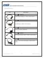
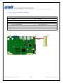
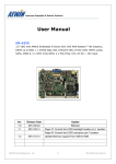
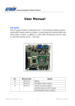
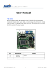
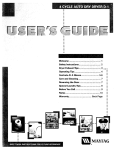
User Manual
EM-6333
3.5” SBC with onboard Intel® Atom™ processor D2550 or N2600, Intel® NM10
chipset, DDR3 up to 4GB, 2 x Intel® Giga LAN, Onboard VGA, LVDS, HDMI,
SATA, 6 x USB, 4 x COM, GPIO, 2 x Mini-PCIe sockets, DC 8V ~ 32V input
Ver.
Release Date
Update
1.0
2013.01.31
Release
AEWIN Technologies Co., Ltd
1
EM-6333 User Manual
Copyright
The content of this document and software with this product are copyrighted by
AEWIN technologies Co., Ltd,
This document contains proprietary information protected by copyright. All rights are
reserved; no part of this manual may be reproduced, copied, translated or transmitted
in any form or by any means without prior written permission of the manufacturer.
The content of this document is intended to be accurate and reliable; the original
manufacturer assumes no responsibility for any inaccuracies that may be contained in
this manual. The original manufacturer reserves the right to make improvements to the
products described in this manual at any time without prior notice
Trademark
All other product names mentioned herein are used for identification purpose only and
may be trademarks and/or registered trademarks of their respective companies
Limitation of liability
While reasonable efforts have been made to ensure the accuracy of this document,
the manufacturer and distributor assume no liability resulting from errors or omissions
in this document, or from the use of the information contained herein.
For more information or other AEWIN products, please visit our website
http://www.aewin.com.tw.
For technical supports, please send your inquiry to [email protected]
AEWIN Technologies Co., Ltd
2
EM-6333 User Manual
Packing list
Before use this product, please make sure that the following materials have been shipped.
1 x EM-6333 3.5” SBC
1 x CPU cooling Fan
( p/n: 49L-F0056-00 )
1 x SATA cable, L/ 200mm
( p/n: 46L-SATA11-00 )
1 x 12V/5V SATA power cable , L/ 150mm
( p/n: 46L-IPOW41-00 )
1 x COM port, DB9 type, L/ 180mm, without bracket
( p/n: 46L-ICOM34-01 )
1 x CD Utilit
p/n: 49L-F0056-00
p/n: 46L-SATA11-00
p/n: 46L-IPOW41-00
p/n: 46L-ICOM34-01
Model Name
Description
EM-6333A-D16
3.5” SBC w/ Intel® Atom™ N2600, 2 GLAN, DDR3 up to 2GB, VGA,
LVDS, HDMI, SATA, COM, Mini-PCIe, DC 8V~32V input.
EM-6333A-D18
3.5” SBC w/ Intel® Atom™ D2550, 2 GLAN, DDR3 up to 4GB, VGA,
LVDS, HDMI, SATA, COM, Mini-PCIe, DC 8V~32V input.
* If any of those items are missing or damaged, please contact with sales representative or distributor
AEWIN Technologies Co., Ltd
3
EM-6333 User Manual
Optional Accessory
Photo
Model Name
P//N:
46L-ICOM34-01
Single COM port, DB9 type, L/ 180mm, without bracket
P//N:
46L-IUSB03-00
Dual USB cable, L/ 245mm, without bracket
P//N:
TBD
DC 5V output cable for SATA SSD
P//N:
46L-IPS200-00
PS/2 Keyboard & Mouse cable, L/ 150mm, without bracket
P//N:
46L-IAUD15-01
Line-out , Line-In , Mic-In audio cable, L/ 180mm, without
bracket
AEWIN Technologies Co., Ltd
4
EM-6333 User Manual
Safety Information
To prevent electrical shock hazard, disconnect the power cable from the electrical
outlet before relocating the system.
When adding or removing devices to or from the system, ensure that the power
cables for the devices are unplugged before the signal cables are connected. If
possible, disconnect all power cables from the existing system before you add a
device.
Before connecting or removing signal cables from the motherboard, ensure that all
power cables are unplugged.
Seek professional assistance before using an adapter or extension cord. These
devices could interrupt the grounding circuit.
Make sure that your power supply is set to the correct voltage in your area.
If you are not sure about the voltage of the electrical outlet you are using, contact
your local power company.
If the power supply is broken, do not try to fix it by yourself. Contact a qualified
service technician or your retailer.
Operation Safety
Before installing the motherboard and adding devices on it, carefully read all the
manuals that came with the package.
Before using the product, make sure all cables are correctly connected and the
power cables are not damaged. If you detect any damage, contact your dealer
immediately.
To avoid short circuits, keep paper clips, screws, and staples away from connectors,
slots, sockets and circuitry.
Avoid dust, humidity, and temperature extremes. Do not place the product in any
area where it may become wet.
Place the product on a stable surface.
If you encounter technical problems with the product, contact a qualified service
technician or your retailer.
AEWIN Technologies Co., Ltd
5
EM-6333 User Manual
Contents
Chapter
Chapter
1
General Information ……………………………………….5
1.1
Introduction HHHHHHHHHHHHHHHH..HHHHHHHH...8
1.2
Specification HHHHHHHHHHHHHHHHHHH..HHH..H...9
1.3
Block Diagram HHHHHHHHHHHHHHHHH.HH.H.............10
1.4
Board layout Dimension HHHHHHHHHHHHHHH.HHHHH..11
1.5
IO / Connector HHHHHHHHHHHHHHHHHHHHHHHHH.13
2
Hardware installation …………………………………….15
2.1
The location of onboard connectors ..HHHHHH..HHHHHHH.15
2.2
The location of onboard jumpers HHHHHHHHHHHHHHH...17
2.3
The function list of onboard jumpers setting HHHHHHHHHHH18
2.3.1
JP1 for LVDS Panel Vcc selectHHHHHHHHHHHHHHH.H...18
2.3.2
JP2 for Clear CMOSHHHHHH.HHHHHHHHHHHHH..HH15
2.4
The pin define of onboard pin header HHHHHHHHHH.HH......18
2.4.1
CN1 for Mini-PCIe WLAN/WWAN LED indicator HHHHH..H...........20
2.4.2
CN2 for LVDS connector ..HHHHHHHHHHHHHHH..H.......21
2.4.3
CN3 for LVDS backlightHHHHHHHHHHHHHHHHHH........23
2.4.4
CN4 for system fan connectorHHHHHHHHH........HHHHH..24
2.4.5
CN5 for CPU fan connector. HHHHHHHHHHHHHHHHH24
2.4.6
CN6 for SATA connector & SATA power connector................................ 25
2.4.7
CN7 for Half-size Mini-PCIe socket .........................................................26
2.4.8
CN8 for audio pin header .......................................................................28
2.4.9
CN9 for DC output for HDD power connector......................................... 29
2.4.10
CN10 for USB2/3...................................................................................30
CN11 for USB4/5 HHHHHHHHHHHHHHHHHHHHHHH.30
2.4.11
CN12 for GPIO pin headerHHHHHHHH......................................... 31
2.4.12
CN13 for SPI programmer ....................................................................32
2.4.13
CN14 for COM2, RS232/422/485 HHHH............................................ 33
2.4.14
CN15 for LPC pin header ....................................................................34
AEWIN Technologies Co., Ltd
6
EM-6333 User Manual
Chapter
2.4.15
CN16 for battery connector ......................................................................35
2.4.16
CN17 for COM3, RS232H. ......................................................................36
2.4.17
CN18 for front panel pin header ................................................................37
2.4.18
CN19 for internal 4-pin power input connector .........................................38
2.4.19
CN20 for keyboard & mouse.....................................................................39
2.4.20
CN23 for COM4, RS232HH.....................................................................40
2.4.21
CN24 for COM1, RS232............................................................................41
2.4.22
CN28 for Full-size Mini-PCIe socket .........................................................42
2.4.23
CN29 for SIM card holder HHHHHHHHHHHHHHHHHHHH.43
3
Programming WDT & GPIO ………………………..44
3.1
GPIO DOS sample code ............HHHHHHHH..HHHHH...HH44
3.2
WatchDog timer DOS sample code .HHHHHHHH ..HHH.H..H.51
AEWIN Technologies Co., Ltd
7
EM-6333 User Manual
1.1 Introduction
EM-6333 is a 3.5” SBC with onboard Intel® Atom™ processor N2600 or D2550 dual core processor
and Intel® NM10 express chipset. Integrated graphics for three display options include HDMI , VGA
and 18/24-bit LVDS. One DDR3 SO-DIMM supports a maximum of 4GB DDR3 800/1066 of system
memory.
There’re two flexible Mini-PCIe sockets for expansion, one is Full-size type and the other one is
half-size type. Both of them are support standard Mini-PCIe card for PCIe & USB signal-base, such as
WIFI. Besides that, A SIM card holder that could install SIM card when install a Full-size Mini-PCIe 3G
module for wireless connection. For the Half-size Mini-PCIe socket, it’s also support mSATA SSD as
storage device.
Regarding I/O ports , EM-6333 provides plenty of connectivity , such as 2 x Intel® gigabit Ethernet
provided by Intel® i211AT controller, 1 x RS232/422/485 & 3 x RS232, 6 x USB2.0, HD Audio, PS/2
Keyboard/Mouse, 1 x SATA 6Gb/s, 1 x LPC pin-header that could support AEWIN’s TPM module if
customer need to protect information.
EM-6333 that could accept wide range DC 8V ~ 32V input, a external DC locking power jack and a
4-pin internal power connector for easier power integration
EM-6333 is a small form-factor embedded platform equip with Intel® Atom low power processor and
also rich IO ports, make EM-6333 suitable for a wide range of applications in digital signage, POS,
kiosks, and factory automation. Fanless design are allowed for high temperature and dusty
environments
AEWIN offers reliable and solid products which are produced under Management System Standards:
ISO9001-2000 Certificate. The certificate keeps us focused on our quality objectives of management
and environmental production. Its willingness to customize standard products for meet unique customer
needs makes AEWIN different. All ODM projects are welcome. Years of experiences enables AEWIN to
fulfill the customer’s vision, by delivering products to exact specifications. AEWIN R&D team is proud of
its strong engineering background. R&D professionals account for 25% of the AEWIN workforce. We
focus on developing new products for both emerging and established markets
For more information about OEM/ODM, please contact us :
Email: [email protected]
AEWIN Technologies Co., Ltd
TEL: +886-2-8692-6677
8
EM-6333 User Manual
1.2 Specification of board
Form Factor
3.5” SBC
CPU
Onboard Intel® Atom N2600 / D2550 processor
Chipset
Intel® NM10 chipset
Memory
1 x DDR3 204-pin SO-DIMM socket up to 4GB ( D2550 )
1 x DDR3 204-pin SO-DIMM socket up to 2GB ( N2600 )
BIOS
AMI® SPI BIOS
Watchdog Timer
255 levels timer interval, (1 ~ 255 seconds), setup by software
Integrated graphic
Build-in Intel® Atom graphic
VGA interface
1 x DB15 external VGA connector
LVDS interface
18/24-bit Single-channel LVDS interface (D2550)
18-bit Single-channel LVDS interface (N2600)
HDMI interface
1 x external HDMI 1.3a spec. interface
SATA interface
1 x SATAII
SSD interface
1 x Half-size Mini-PCIe socket support mSATA .
Ethernet
2 x Intel® i211AT
Audio interface
1 x Realtek ALC886 codec
Expansion interface
1 x Full-size Mini-PCIe socket w/ SIM socket ( PCIe X1 + USB2.0 signal )
1 x Half-size Mini-PCIe socket ( PCIe X1 / SATA2.0 + USB2.0 signal )
COM
Internal: 3 x RS232, 1 x RS422/485 ( COM2 )
USB
Internal: 4 x USB 2.0
External: 2 x USB 2.0
GPIO
8-bit programmable GPIO interface
Low Pin Count
1 x Low Pin Count ( Support AEWIN’s TPM module )
Power Input
Wide range DC 8V ~ 32V input
x 12V/5V
1 x 5V to
DCchange
output without
headernotice
Other
IO
Note : Internal
All specifications
and1photos
are&subject
1 x LVDS Voltage select,
1 x LVDS inverter,
1 x PS/2 K/M
Reset, HDD/Power LED header
Operating temperature
0°C ~ 60°C
AEWIN Technologies Co., Ltd
9
EM-6333 User Manual
1.3 Block Diagram
VGA
DDR3
VGA
1 x DDR3 204-pin SO-DIMM
Intel® Atom Cedarview
DDI0
HDMI
Processor
LVDS
18/24 single channel LVDS
Level Shifter
PCIe
LPC
2 x Intel® i211AT
Fintek F81866A
Full-Size Mini-PCIe w/ SIM
PCIe
Intel® NM10
USB
Chipset
3 x RS232 + 1 x RS422/485
8-bit GPIO, PS/2 K/M
USB
6 x USB 2.0
PCIe/SATA
Half Mini-PCIe
Switch
LPC
1 x LPC header for
TPM ( Optional )
SATA
1 x SATAII
SPI
BIOS
HD audio
ALC886 HD Audio
AEWIN Technologies Co., Ltd
10
EM-6333 User Manual
1.4 Board Layout Dimension
AEWIN Technologies Co., Ltd
11
EM-6333 User Manual
AEWIN Technologies Co., Ltd
12
EM-6333 User Manual
1.5 IO ports
External DC input
VGA
HDMI
GLAN GLAN
Dual USB 2.0
w/ Locking
PS/2 Key/Mouse
Internal DC input
4 x COM
Power On/Off
SPI Flash
GPIO
4 x USB2.0
Intel® Atom CPU
Audio
DC output
LVDS
Intel® NM10
Mini-PCIe
SATA
DDR3 SO-DIMM
SIM holder
Mini-PCIe
AEWIN Technologies Co., Ltd
13
EM-6333 User Manual
Gigabit Ethernet
Dual USB 2.0
AEWIN Technologies Co., Ltd
Gigabit Ethernet
HDMI
14
DC input with Locking
VGA
EM-6333 User Manual
2.1 The location of onboard connectors
CN26
CN32
CN31
CN27
CN22
CN24
CN18
CN21
CN25
CN23
CN19
CN20
CN17
CN14
CN15
CN13
CN12
CN10
CN11
CN8
CN9
PW1
CN4
CN5
CN1
CN16
CN2 CN3
CN7
CN6
SO-DIMM
CN29
CN28
AEWIN Technologies Co., Ltd
15
EM-6333 User Manual
Label
Function
Label
Function
CN1
WLAN/WWAN LED Pin header
CN17
COM3 / RS232 Pin header
CN2
LVDS Pin header
CN18
Reset, HDD/Power LED Pin header
CN3
Backlight Pin header
CN19
4-pin internal DC input connector
CN4
System Fan header
CN20
PS/2 Keyboard & Mouse Pin header
CN5
CPU Fan header
CN21
Gigabit Ethernet connector
CN6
SATA 2.0 connector
CN22
Gigabit Ethernet connector
CN7
Half-size Mini-PCIe socket
CN23
COM4 / RS232 Pin header
CN8
Audio Pin header
CN24
COM1 / RS232 Pin header
CN9
DC 5V output for SSD Pin header
CN25
Dual USB 2.0 connector
CN10
USB 2.0 Pin header
CN26
HDMI connector
CN11
USB 2.0 Pin header
CN27
DB15 VGA connector connector
CN12
8-bit GPIO Pin header
CN28
Full-size Mini-PCIe socket
CN13
SPI Flash Pin header
CN29
SIM holder
CN14
COM2 / RS232/422/485 Pin header
CN30
N/A
CN15
Low Pin Count Pin header
CN31
Power On/Off switch ( N/C )
CN16
CMOS Battery header
CN32
External DC input power connector
AEWIN Technologies Co., Ltd
16
EM-6333 User Manual
2.2 The location of onboard jumpers
JP2
JP5
PW1
JP1
Label
Function
JP1
Panel Voltage
JP2
CMOS Clear jumper
PW1
12V/5V DC output
AEWIN Technologies Co., Ltd
( VCC ) select
17
EM-6333 User Manual
2.3 The function list of onboard jumpers setting
- 2.3.1 : JP1 for LVDS Panel Vcc select
JP1
Closed Pin
Result
1-2 *
+3.3V
2-3
+5V
* Default setting
3
JP1
1
AEWIN Technologies Co., Ltd
18
EM-6333 User Manual
- 2.3.2 : JP2 for Clear CMOS
If you want to clean the CMOS data, set jumper to 2-3 just for few seconds, Then,
Move the jumper back to 1-2 pin
JP2
Closed Pin
Result
1-2 *
Normal
2-3
Clear CMOS
* Default setting
JP2
3
1
AEWIN Technologies Co., Ltd
19
EM-6333 User Manual
2.4 The pin define of onboard pin header
- 2.4.1 : CN1 for Mini-PCIe WLAN/WWAN LED indicator
CN1: 1 x 2 header , Picth 2.0mm
Pin
Signal
Pin
Signal
1
LED1_WLAN
2
LED_WLAN
CN1
2
1
AEWIN Technologies Co., Ltd
20
EM-6333 User Manual
-
2.4.2 : CN2 for LVDS connector
CN2 : 2 x 10 header , connector type : DF13A-20DP-1.25V
Pin
Signal
Pin
Signal
1
LVDS_TXP0
2
LVDS_TXN0
3
GND
4
GND
5
LVDS_TXP1
6
LVDS_TXN1
7
GND
8
VCC_LCD
9
LVDS_TXP2
10
LVDS_TXN2
11
LVDS_CLKP
12
LVDS_CLKN
13
GND
14
GND
15
LVDS_TXP3
16
LVDS_TXN3
17
LBKLT_EN_DELAY
18
VCC_LCD
19
LVDS_DDC_DATA
20
LVDS_DDC_CLK
20
2
19
1
AEWIN Technologies Co., Ltd
CN2
21
EM-6333 User Manual
BIOS setting for LVDS Resolution:
BIOS setting for LVDS Enable:
AEWIN Technologies Co., Ltd
22
EM-6333 User Manual
- 2.4.3 : CN3 for LVDS backlight
CN3: 1 x 5 header , Pitch : Pitch 2.0 mm
Pin
Signal
Pin
Signal
1
+12V
2
GND
3
LBKLT_EN_DELAY
4
LCD_BKB_CTRL
5
VCC5
CN3
5
AEWIN Technologies Co., Ltd
1
23
EM-6333 User Manual
- 2.4.4 : CN4 for system Fan connector
CN4 : 1 x 3 wafer
-
Pin
Signal
Pin
Signal
1
GND
2
SYSFAN_VIN
3
SYSFAN_SEN
2.4.5 : CN5 for CPU Fan connector
CN5: 1 x 3 wafer
Pin
Signal
Pin
Signal
1
GND
2
CPUFAN_VIN
3
CPUFAN_SEN
1
CN5
3
1
CN4
3
AEWIN Technologies Co., Ltd
24
EM-6333 User Manual
- 2.4.6 : CN6 for SATA 2.0 connector and SATA power connector
CN6 : SATA 2.0 connector
Pin
Signal
Pin
Signal
1
GND
2
SATA_TX_P0
3
SATA_TX_N0
4
GND
5
SATA_RX_N0
6
SATA_RX_P0
7
GND
PW1 : 4-pin wafer for SATA power connector
Pin
Signal
Pin
Signal
1
+12V
2
GND
3
GND
4
+5V
Note: Maximum output current 12V/2A, 5V/2A
4
PW1
1
CN6
1
7
AEWIN Technologies Co., Ltd
25
EM-6333 User Manual
- 2.4.7 : CN7 for half-size Mini-PCIe socket
CN7 : Half-size Mini-PCIe socket
Pin
Signal
Pin
Signal
Pin
Signal
1
MSATA_WAKE
19
N/C
37
N/A
2
+3.3V
20
N/C
38
USB_D+
3
N/C
21
GND
39
V3P3_MSATA
4
GND
22
PLTRST_BUF1_N
40
GND
5
N/C
23
MSATA_RXN4
41
V3P3_MSATA
6
+1.5V
24
MSATA_AUX33
42
LED_WWAN
7
MCLKREQ
25
MSATA_RXP4
43
N/A
8
N/C
26
GND
44
LED_WLAN
9
GND
27
GND
45
N/A
10
N/C
28
+1.5V
46
LED_WPAN
11
MSATA_PE_CLKN
29
GND
47
N/A
12
N/C
30
ICH_SMBCLK
48
+1.5V
13
MSATA_PE_CLKP
31
MSATA_TXN4
49
N/A
14
N/C
32
ICH_SMBDATA
50
GND
15
GND
33
MSATA_TXP4
51
N/A
16
N/C
34
GND
52
+3.3V
17
N/C
35
18
N/C
36
USB_D-
-
1
51
2
52
CN7
AEWIN Technologies Co., Ltd
26
EM-6333 User Manual
Half-size Mini-PCIe socket could support standard Mini-PCIe card or mSATA SSD.
Please into BIOS and select SATA or PCIe signal to match your card as below .
AEWIN Technologies Co., Ltd
27
EM-6333 User Manual
-
2.4.8 : CN8 for Audio
CN8: 2 x 5 header , Pitch 2.0mm
Pin
Signal
Pin
Signal
1
LINE1-LL
2
LINE1-RR
3
GND
4
GND
5
N/C
6
MIC1_R_L
7
-
8
GND
9
SPKR_OUT_L
10
SPKR_OUT_R
10
9
CN8
2
AEWIN Technologies Co., Ltd
28
1
EM-6333 User Manual
-
2.4.9 : CN9 for DC output for HDD power
CN1: 1 x 2 header , Picth 2.0mm
Pin
Signal
Pin
Signal
1
GND
2
+5V
Note: Maximum output current 5V/1A. And it’s share with PW1 4-pin / 5V power connector
CN9
AEWIN Technologies Co., Ltd
29
2
1
EM-6333 User Manual
2.4.10 : CN10 for USB 2/3
CN10: 2 x 5 header , pitch 2.0 mm
Pin
Signal
Pin
Signal
1
+5V
2
+5V
3
USB_PN_2
4
USB_PN_3
5
USB_PP_2
6
USB_PP_3
7
GND
8
GND
10
GND
9
-
CN11 for USB 4/5
CN10: 2 x 5 header , pitch 2.0 mm
Pin
Signal
Pin
Signal
1
+5V
2
+5V
3
USB_PN_4
4
USB_PN_5
5
USB_PP_4
6
USB_PP_5
7
GND
8
GND
10
GND
9
-
10
1
CN10
10
CN11
1
AEWIN Technologies Co., Ltd
30
EM-6333 User Manual
- 2.4.11 : CN12 for GPIO pin header
CN12 : 2 x 4 header , pitch 2.0 mm
Pin
Signal
Pin
Signal
1
GPIO0
2
GPIO4
3
GPIO1
4
GPIO5
5
GPIO2
6
GPIO6
7
GPIO3
8
GPIO7
CN12
8
1
AEWIN Technologies Co., Ltd
31
EM-6333 User Manual
-
2.4.12 : CN13 for SPI programmer
CN13 : 2 x 4 header , pitch 2.54 mm
Pin
Signal
Pin
Signal
1
VCC3
2
GND
3
SF_SPI_CS0_N
4
SF_SPI_CLK
5
SF_SPI_MISO
6
SF_SPI_MOSI
7
N/C
8
FLASH_IO
CN13
8
1
AEWIN Technologies Co., Ltd
32
EM-6333 User Manual
-
2.4.13 : CN14 for COM 2 , RS232/422/485
Note: COM2 RS-232/422/485 can be set by BIOS setting. Default is RS-232.
CN14 : Wafer 1 x 10 header, pitch 1.25 mm, connector type : YIMTEX 501MW1*10STR
Pin
Signal
Pin
Signal
1
DCD, Data carrier detect
2
DSR, Data set ready
3
RXD, Receive data
4
RTS, Request to send
5
TXD, Transmit data
6
CTS, Clear to se
7
DTR, Data terminal ready
8
RI, Ring indicator
9
GND, Ground
10
VCC5, +5V
10
CN14
1
BIOS setting manual :
AEWIN Technologies Co., Ltd
33
EM-6333 User Manual
- 2.4.14 : CN15 for LPC connector
CN15 : 2 x 7 header , pitch 2.0 mm
Pin
Signal
Pin
Signal
1
+V3P3
2
LAD0
3
LAD1
4
LAD2
5
LAD3
6
LFRAME_N
7
PLTRST_N
8
+5VP0
9
PORT80_PCLK
10
GND
11
GND
13
ICH_SERIRQ
14
LDRQ0_N
14
CN15
1
AEWIN Technologies Co., Ltd
34
EM-6333 User Manual
- 2.4.15 : CN16 for Battery connector
CN16 : 1 x 2 header , pitch 2.0 mm
Pin
Signal
Pin
Signal
1
BAT1_R
2
GND
CN16
1
AEWIN Technologies Co., Ltd
35
2
EM-6333 User Manual
-
2.4.16 : CN17 for COM 3 , RS232
CN17 : Wafer 1 x 10 header, pitch 1.25 mm, connector type : YIMTEX 501MW1*10STR
Pin
Signal
Pin
Signal
1
DCD, Data carrier detect
2
DSR, Data set ready
3
RXD, Receive data
4
RTS, Request to send
5
TXD, Transmit data
6
CTS, Clear to se
7
DTR, Data terminal ready
8
RI, Ring indicator
9
GND, Ground
10
VCC5, +5V
10
CN17
1
AEWIN Technologies Co., Ltd
36
EM-6333 User Manual
-
2.4.17 : CN18 for front Panel pin header
CN18 : 2 x 3 header , pitch 2.00 mm
Pin
Signal
Pin
Signal
1
HDD_LED_N
2
ICH_SATA_LED_N
3
LED1_R
4
GND
5
RESET_L
6
GND
6
CN18
AEWIN Technologies Co., Ltd
37
1
EM-6333 User Manual
-
2.4.18 : CN19 for internal 4-pin power input
CN19 : ATX 2 x 2
Pin
Signal
Pin
Signal
1
GND
2
GND
3
Power Input
4
Power Input
4
3
CN19
2
AEWIN Technologies Co., Ltd
1
38
EM-6333 User Manual
-
2.4.19 : CN20 for keyboard & mouse
CN20 : 2 x 5 header , pitch 2.54 mm
Pin
Signal
Pin
Signal
1
Keyboard clock
2
Mouse clock
3
Keyboard data
4
Mouse data
Key
6
N/C
7
GND
8
GND
9
VCC5
10
VCC5
10
CN20
1
AEWIN Technologies Co., Ltd
39
EM-6333 User Manual
-
2.4.20 : CN23 for COM 4 , RS232
CN23 : Wafer 1 x 10 header, pitch 1.25 mm, connector type : YIMTEX 501MW1*10STR
Pin
Signal
Pin
Signal
1
DCD, Data carrier detect
2
DSR, Data set ready
3
RXD, Receive data
4
RTS, Request to send
5
TXD, Transmit data
6
CTS, Clear to se
7
DTR, Data terminal ready
8
RI, Ring indicator
9
GND, Ground
10
VCC5, +5V
10
CN23
1
AEWIN Technologies Co., Ltd
40
EM-6333 User Manual
-
2.4.21 : CN24 for COM 1 , RS232
CN24 : Wafer 1 x 10 header, pitch 1.25 mm, connector type : YIMTEX 501MW1*10STR
Pin
Signal
Pin
Signal
1
DCD, Data carrier detect
2
DSR, Data set ready
3
RXD, Receive data
4
RTS, Request to send
5
TXD, Transmit data
6
CTS, Clear to se
7
DTR, Data terminal ready
8
RI, Ring indicator
9
GND, Ground
10
VCC5, +5V
10
CN24
1
AEWIN Technologies Co., Ltd
41
EM-6333 User Manual
- 2.4.22 : CN28 for full-size Mini-PCIe socket
CN28 : Full-size Mini-PCIe socket
Pin
Signal
Pin
Signal
Pin
Signal
1
MSATA_WAKE
19
N/C
37
N/A
2
+3.3V
20
N/C
38
USB_D+
3
N/C
21
GND
39
V3P3_MSATA
4
GND
22
PLTRST_BUF1_N
40
GND
5
N/C
23
MSATA_RXN4
41
V3P3_MSATA
6
+1.5V
24
MSATA_AUX33
42
LED_WWAN
7
MCLKREQ
25
MSATA_RXP4
43
N/A
8
N/C
26
GND
44
LED_WLAN
9
GND
27
GND
45
N/A
10
N/C
28
+1.5V
46
LED_WPAN
11
MSATA_PE_CLKN
29
GND
47
N/A
12
N/C
30
ICH_SMBCLK
48
+1.5V
13
MSATA_PE_CLKP
31
MSATA_TXN4
49
N/A
14
N/C
32
ICH_SMBDATA
50
GND
15
GND
33
MSATA_TXP4
51
N/A
16
N/C
34
GND
52
+3.3V
17
N/C
35
18
N/C
36
1
51 CN28
2
52
AEWIN Technologies Co., Ltd
USB_D-
-
42
EM-6333 User Manual
-
2.4.23 : CN29 for SIM holder
CN29 : SIM card holder
Pin
Signal
Pin
Signal
C1
SIM_PWR
C2
SIM_RESET
C3
SIM_CLK
C4
Reserved
C5
GND
C6
SIM_VPP
C7
SIM_DATA
C8
Reserved
C8
C5
51
CN29
C4
AEWIN Technologies Co., Ltd
C1
43
EM-6333 User Manual
3.1 GPIO Sample Program for DOS environment
//AEWIN GPIO Program for EM-6333(DOS Version)
#include <stdio.h>
#include <string.h>
#include <dos.h>
#include <stdlib.h>
#include <inlines/pc.h>
#define index_port 0x2E
#define data_port 0x2F
void help();
void Enter_SIO();
void Exit_SIO();
int main(int argc, char *argv[])
{
int data_rw8, val;
if (argc!=2){
help();
return;
}
Enter_SIO();
if(strcmp(argv[1], "-80h") == 0){
val = 0x01;
outportb(index_port, 0x89);
data_rw8 = inportb(data_port)&(~val);
data_rw8 |= val;
outportb(data_port, data_rw8);
printf("(Set GP80 to high)\n");
}
else if(strcmp(argv[1], "-80l") == 0){
AEWIN Technologies Co., Ltd
44
EM-6333 User Manual
val = 0x01;
outportb(index_port, 0x89);
data_rw8 = inportb(data_port)&(~val);
outportb(data_port, data_rw8);
printf("(Set GP80 to low)\n");
}
else if(strcmp(argv[1], "-81h") == 0){
val = 0x02;
outportb(index_port, 0x89);
data_rw8 = inportb(data_port)&(~val);
data_rw8 |= val;
outportb(data_port, data_rw8);
printf("(Set GP81 to high)\n");
}
else if(strcmp(argv[1], "-81l") == 0){
val = 0x02;
outportb(index_port, 0x89);
data_rw8 = inportb(data_port)&(~val);
outportb(data_port, data_rw8);
printf("(Set GP81 to low)\n");
}
else if(strcmp(argv[1], "-82h") == 0){
val = 0x04;
outportb(index_port, 0x89);
data_rw8 = inportb(data_port)&(~val);
data_rw8 |= val;
outportb(data_port, data_rw8);
printf("(Set GP82 to high)\n");
}
else if(strcmp(argv[1], "-82l") == 0){
val = 0x04;
outportb(index_port, 0x89);
data_rw8 = inportb(data_port)&(~val);
outportb(data_port, data_rw8);
printf("(Set GP82 to low)\n");
}
else if(strcmp(argv[1], "-83h") == 0){
AEWIN Technologies Co., Ltd
45
EM-6333 User Manual
val = 0x08;
outportb(index_port, 0x89);
data_rw8 = inportb(data_port)&(~val);
data_rw8 |= val;
outportb(data_port, data_rw8);
printf("(Set GP83 to high)\n");
}
else if(strcmp(argv[1], "-83l") == 0){
val = 0x08;
outportb(index_port, 0x89);
data_rw8 = inportb(data_port)&(~val);
outportb(data_port, data_rw8);
printf("(Set GP83 to low)\n");
}
else if(strcmp(argv[1], "-84h") == 0){
val = 0x10;
outportb(index_port, 0x89);
data_rw8 = inportb(data_port)&(~val);
data_rw8 |= val;
outportb(data_port, data_rw8);
printf("(Set GP84 to high)\n");
}
else if(strcmp(argv[1], "-84l") == 0){
val = 0x10;
outportb(index_port, 0x89);
data_rw8 = inportb(data_port)&(~val);
outportb(data_port, data_rw8);
printf("(Set GP84 to low)\n");
}
else if(strcmp(argv[1], "-85h") == 0){
val = 0x20;
outportb(index_port, 0x89);
data_rw8 = inportb(data_port)&(~val);
data_rw8 |= val;
outportb(data_port, data_rw8);
printf("(Set GP85 to high)\n");
}
AEWIN Technologies Co., Ltd
46
EM-6333 User Manual
else if(strcmp(argv[1], "-85l") == 0){
val = 0x20;
outportb(index_port, 0x89);
data_rw8 = inportb(data_port)&(~val);
outportb(data_port, data_rw8);
printf("(Set GP85 to low)\n");
}
else if(strcmp(argv[1], "-86h") == 0){
val = 0x40;
outportb(index_port, 0x89);
data_rw8 = inportb(data_port)&(~val);
data_rw8 |= val;
outportb(data_port, data_rw8);
printf("(Set GP86 to high)\n");
}
else if(strcmp(argv[1], "-86l") == 0){
val = 0x40;
outportb(index_port, 0x89);
data_rw8 = inportb(data_port)&(~val);
outportb(data_port, data_rw8);
printf("(Set GP86 to low)\n");
}
else if(strcmp(argv[1], "-87h") == 0){
val = 0x80;
outportb(index_port, 0x89);
data_rw8 = inportb(data_port)&(~val);
data_rw8 |= val;
outportb(data_port, data_rw8);
printf("(Set GP87 to high)\n");
}
else if(strcmp(argv[1], "-87l") == 0){
val = 0x80;
outportb(index_port, 0x89);
data_rw8 = inportb(data_port)&(~val);
outportb(data_port, data_rw8);
printf("(Set GP87 to low)\n");
}
AEWIN Technologies Co., Ltd
47
EM-6333 User Manual
else if(strcmp(argv[1], "-hhh") == 0){
val = 0xFF;
outportb(index_port, 0x89);
data_rw8 = inportb(data_port);
data_rw8 |= val;
outportb(data_port, data_rw8);
printf("(Set GP80~87 to high)\n");
}
else if(strcmp(argv[1], "-lll") == 0){
val = 0x00;
outportb(index_port, 0x89);
data_rw8 = inportb(data_port);
data_rw8 &= val;
outportb(data_port, data_rw8);
printf("(Set GP80~87 to low)\n");
}
else if(strcmp(argv[1], "-lte") == 0){
val = 0x0F;
outportb(index_port, 0x89);
data_rw8 = inportb(data_port)&0x00;
data_rw8 |= val;
outportb(data_port, data_rw8);
printf("(Set GP80~83 to high, GP84~87 to low)\n");
}
else if(strcmp(argv[1], "-ltd") == 0){
val = 0xF0;
outportb(index_port, 0x89);
data_rw8 = inportb(data_port)&0x00;
data_rw8 |= val;
outportb(data_port, data_rw8);
printf("(Set GP80~83 to low, GP84~87 to high)\n");
}
else if(strcmp(argv[1], "-gpr") == 0){
outportb(index_port, 0x8A);
val = 0x01;
data_rw8 = inportb(data_port)&(val);
AEWIN Technologies Co., Ltd
48
EM-6333 User Manual
if(data_rw8==val)printf("(GP80 is high)\n");
else printf("(GP80 is low)\n");
val = 0x02;
data_rw8 = inportb(data_port)&(val);
if(data_rw8==val)printf("(GP81 is high)\n");
else printf("(GP81 is low)\n");
val = 0x04;
data_rw8 = inportb(data_port)&(val);
if(data_rw8==val)printf("(GP82 is high)\n");
else printf("(GP82 is low)\n");
val = 0x08;
data_rw8 = inportb(data_port)&(val);
if(data_rw8==val)printf("(GP83 is high)\n");
else printf("(GP83 is low)\n");
val = 0x10;
data_rw8 = inportb(data_port)&(val);
if(data_rw8==val)printf("(GP84 is high)\n");
else printf("(GP84 is low)\n");
val = 0x20;
data_rw8 = inportb(data_port)&(val);
if(data_rw8==val)printf("(GP85 is high)\n");
else printf("(GP85 is low)\n");
val = 0x40;
data_rw8 = inportb(data_port)&(val);
if(data_rw8==val)printf("(GP86 is high)\n");
else printf("(GP86 is low)\n");
val = 0x80;
data_rw8 = inportb(data_port)&(val);
if(data_rw8==val)printf("(GP87 is high)\n");
else printf("(GP87 is low)\n");
AEWIN Technologies Co., Ltd
49
EM-6333 User Manual
}
else{
help();
}
Exit_SIO();
return;
}
void Enter_SIO()
{
outportb(index_port, 0x87);
delay(1);
outportb(index_port, 0x87);
outportb(index_port, 0x07);
outportb(data_port,
0x06);
}
void Exit_SIO()
{
outportb(index_port, 0xAA);
}
void help()
{
printf("AEWIN GPIO test program\n");
printf("==============================================\n");
printf("gpio -hhh (Set GP80~87 to high)\n");
printf("gpio -lll (Set GP80~87 to low )\n");
printf("gpio -lte (Set GP80~83 to high, GP84~87 to low)\n");
printf("gpio -ltd (Set GP80~83 to low, GP84~87 to high)\n");
printf("gpio -gpr (Read GPIO status)\n");
printf("gpio -xxh (Set xx to high)\n");
printf("gpio -xxl (Set xx to low)\n");
printf("
(xx=80~87)\n");
printf("==============================================\n");
}
AEWIN Technologies Co., Ltd
50
EM-6333 User Manual
3.2 Watchdog timer Sample Program for DOS environment
//AEWIN Watch dog program for EM-6333(Dos Version)
#include <stdio.h>
#include <string.h>
#include <dos.h>
#include <stdlib.h>
#include <inlines/pc.h>
#define index_port 0x2E
#define data_port 0x2F
//Super IO Index port address
//Super IO Data port address
void Enter_sio_config();
void Exit_sio_config();
void help();
int main(int argc, char *argv[])
{
int data_rw8, time;
if (argc<2){
help();
return;
}
if(strcmp(argv[1], "-s") == 0){
//Show Watchdog Register Settings
Enter_sio_config();
outportb(index_port, 0xF5);
data_rw8 = inportb(data_port)&0x08;
if(data_rw8 == 0x00){
//second mode
outportb(index_port, 0xF6);
data_rw8 = inportb(data_port);
printf("Second mode: %d second\n", data_rw8);
}
AEWIN Technologies Co., Ltd
51
EM-6333 User Manual
else{
//minute mode
outportb(index_port, 0xF6);
data_rw8 = inportb(data_port);
printf("Minute mode: %d minute\n", data_rw8);
}
}
else if(strcmp(argv[1], "-t") ==0 ){
//Set Time-out Value
if(argv[2] == NULL){
help();
return;
}
else{
Enter_sio_config();
outportb(index_port, 0xF6);
outportb(data_port , 0x00);
outportb(index_port, 0xF5);
data_rw8 = 0x32;
//Clear Status
outportb(data_port, data_rw8);
sscanf(argv[2], "%d", &time);
outportb(index_port, 0xF6);
outportb(data_port, time);
if(time==0){
//Disable count
outportb(index_port, 0xF5);
data_rw8 = inportb(data_port)&0xCF;
outportb(data_port , data_rw8);
}
else{
outportb(index_port, 0xFA);
outportb(data_port , 0x01);
//Enable reset function
}
printf("Watchdog Timer will count down for %d second(s)\n", time);
}
}
else if(strcmp(argv[1], "-m") ==0 ){
AEWIN Technologies Co., Ltd
52
EM-6333 User Manual
//Set Time-out Value
if(argv[2] == NULL){
help();
return;
}
else{
Enter_sio_config();
outportb(index_port, 0xF6);
outportb(data_port , 0x00);
outportb(index_port, 0xF5);
data_rw8 = 0x32;
data_rw8 |= 0x08;
//Clear Status
outportb(data_port, data_rw8);
sscanf(argv[2], "%d", &time);
outportb(index_port, 0xF6);
outportb(data_port, time);
if(time==0){
//Disable count
outportb(index_port, 0xF5);
data_rw8 = inportb(data_port)&0xCF;
outportb(data_port , data_rw8);
}
else{
outportb(index_port, 0xFA);
outportb(data_port , 0x01);
//Enable reset function
}
printf("Watchdog Timer will count down for %d minute(s)\n", time);
}
}
Exit_sio_config();
return;
}
void Enter_sio_config()
{
outportb(index_port, 0x87);
delay(1);
AEWIN Technologies Co., Ltd
//Enter W83627EHF Configuration
//Delay some time
53
EM-6333 User Manual
outportb(index_port, 0x87);
outportb(index_port, 0x07);
outportb(data_port , 0x07);
//Super IO Selct Bank Register Number
//Select logical device 7
}
void Exit_sio_config()
{
outportb(index_port, 0xAA);
//Exit W83627EHF Configuration
}
void help()
{
printf("AEWIN Watchdog Timer Program\n");
printf("Usage: WDT -s
(Show Watchdog Register Settings)\n");
printf("Usage: WDT -t xxx (Set Time-out Value)\n");
printf("
xxx = 1 ~ 255 seconds\n");
printf("
xxx = 0 : Time-out Disable \n");
printf("Usage: WDT -m xxx (Set Time-out Value)\n");
printf("
xxx = 1 ~ 255 minutes\n");
printf("
xxx = 0 : Time-out Disable \n");
}
AEWIN Technologies Co., Ltd
54
EM-6333 User Manual