1
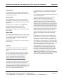
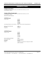
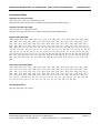
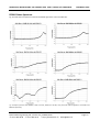
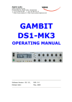
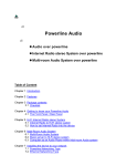
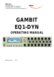
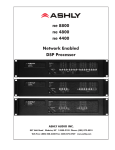
digital audio
weiss engineering ltd.
Florastrasse 42, 8610 Uster, Switzerland
+41 44 940 20 06 +41 44 940 22 14
http://www.weiss.ch / http://www.weiss-highend.com
WEISS
GAMBIT
ADC2
OPERATING MANUAL
Software Version:
3.1
Firewire option update 12.10.2011
OPERATING INSTRUCTIONS FOR GAMBIT ADC2 24Bit / 192kHz A/D CONVERTER
INTRODUCTION
INTRODUCTION
Congratulations on purchasing the Weiss Gambit Series ADC2 A/D Converter !
The ADC2 is a two channel A/D converter designed for
most demanding audio applications. It uses state of
the art A/D chips in Weiss Engineering’s proven
“correlation technique” configuration, which lowers
converter imperfections and improves the SNR ratio.
Summary of ADC2 features:
For best noise rejection, the analogue input signal is
kept balanced from the input connectors up to the
converter chips. A high quality microphone preamp is
available as a standard feature.
•
Two balanced LINE and two MIC inputs on
separate XLR connectors.
•
MIC input with switchable phantom power.
•
Input sensitivity is settable in each channel
independently (or ganged) with two rotary
encoders.
•
Line Input sensitivity: -16dBu to +26 dBu.
•
Mic Input sensitivity: -54dBu to +6dBu.
•
Separate AES/EBU input on XLR for
synchronization and/or audio input to the DSP,
which allows for use of the ADC2 for redithering
and limiting of digital signals.
Additionally, there is a built-in digital two-segment
compressor / limiter for optimal levelling, employing
adaptive release timing, look-ahead circuitry and
sidechain-oversampling for mastering-quality
dynamics processing.
Large bar graphs, a well thought-out push button
array and uncluttered rotary knobs optimize handling
ergonomics.
Inputs
Synchronization
•
Internal sync selectable 44.1kHz, 48kHz, 88.2kHz,
96kHz, 176.4kHz, 192kHz.
•
External sync from Wordsync Input (BNC) or from
AES/EBU input.
•
Wordsync output on a BNC connector.
Metering
•
One input / output level bargraph per channel
with short peak hold
•
One gain reduction bargraph per channel.
•
Two over LEDs
•
Two numerical displays for peak hold and level
settings.
•
Reference for level setting can be altered
Daniel Weiss Engineering Ltd., Florastr. 42, CH-8610 Uster
+41 44 940 20 06 +41 44 940 22 14 http://www.weiss. ch [email protected]
Page 2
OPERATING INSTRUCTIONS FOR GAMBIT ADC2 24Bit / 192kHz A/D CONVERTER
INTRODUCTION
Outputs
•
AES/EBU on XLR in one or two wire format
•
S/PDIF on RCA
•
Firewire (Optional, a kit is available)
DSP
•
POW-R dithering to 16 bits, settable to three
different algorithms according to the POW-R
standard
•
SNR enhancement
•
Level bar graph meter
•
Two segment compressor / peak limiter
•
Double-precision 40bit floating-point processing
Daniel Weiss Engineering Ltd., Florastr. 42, CH-8610 Uster
+41 1 940 20 06 +41 1 940 22 14 http://www.weiss. ch [email protected]
Page 3
OPERATING INSTRUCTIONS FOR GAMBIT ADC2 24Bit / 192kHz A/D CONVERTER
OPERATION
OPERATION
ADC2 Block Diagram
Fig. 1 ADC2 Block Diagram Schematic
1
Input Control Panel
compressor / limiter links the sidechains of the two
channels. Typical applications for “ganged” mode are
This section describes how to use the input control
panel (see Fig. 2).
•
stereo (left/right) recordings with two
microphones
•
stereo insert limiting (during mixdown or
mastering).
Fig. 2 ADC2 Input Control Panel
If “ganged” is not active, channel 1 and channel 2
settings are independent and the compressor / limiter
works unlinked. Thus the ADC2 can also be used in a
studio recording / mixing environment as dual channel
outboard compressor / limiter.
Ganged
For stereo use, press the “ganged” key. This locks
together channel 1 and channel 2 gain and threshold
controls. Additionally, if “ganged” is active, the
1
“sidechain linking ” means that the same gain reduction is
applied to both channels to avoid corrupting the stereo
balance.
Daniel Weiss Engineering Ltd., Florastr. 42, CH-8610 Uster
+41 1 940 20 06 +41 1 940 22 14 http://www.weiss. ch [email protected]
Page 4
OPERATING INSTRUCTIONS FOR GAMBIT ADC2 24Bit / 192kHz A/D CONVERTER
OPERATION
Pressing the “digtial in” key activates the digital
AES/EBU XLR input, the key lights red if active. As soon
as a valid signal is present, the sampling rate is
displayed with the sampling rate keys (see Fig. 6).
The level bargraph is switched between input and
output in the same manner as the peak hold. Thus, if
the “input gain” key is lit, the bargraph displays the
input peak meter. If the “output gain” key is lit, the
bargraph displays the ouput peak meter (settings can
be different if “ganged” is not lit).
If the digital input stage does not lock to any signal,
none of the sampling rate keys are lit.
Refer to Fig. 1 on p. 4 for positioning of input and
output peak meter in the processing chain.
If the “digital in” key is not lit, the analogue inputs are
selected. To activate the microphone input for either
channel, press the appropriate “mic” key (if “ganged”
is active, pressing one “mic” key will select
microphone inputs for both channels). Press “+48V” if
phantom power is needed.
Note: The reference for the input sensitivity display
can be chosen by the user. For that purpose press and
hold the “ganged” key and then switch the ADC2 on.
After a few seconds release the ganged key. Wait for a
few more seconds. Now you can select the reference
with the righthand knob. This allows to set the
reference to e.g. +4dBu. Factory setting is 0 dBu
reference.
When finished press the blinking “peak hold” key. The
setting is retained in non-volatile memory.
Digital In / Mic
It is usually advisable to use “low-cut” when recording
with microphones. If “low-cut” is lit, low frequency
content (traffic rumble, building tremors, air-condition
hum and other low-frequency air movement like doors
opening or closing near the microphone etc.) is filtered
out.
Peak Hold
If “peak hold” is lit, the numeric display shows the
peak hold value (in dBFS) which is selected by the gain
key: “input gain” selects the input peak hold, “output
gain” selects the output peak hold (“threshold” also
selects output peak hold). See Fig. 1 for positioning of
input and output peak hold in the processing chain.
If input peak hold is selected, values equal to or above
0.0dBFS are indicated by “>=0”. The output peak hold
however can measure values above 0.0dBFS because
of the internal floating-point data format used in the
digital signal processor. This is very useful to set the
output gain.
Output Gain
If “output gain” is lit, the rotary knobs control the
digital output gain. This gain can be used for optimal
gain adjustment and to drive the peak limiter (see
below).
The gain ranges from -∞ (off) to +18.0 dB, the
resolution is optimized for fine control around 0.0 dB
while still allowing complete fade-out. A special
algorithm is used for click-free gain transitions (no
“zipper” noise).
To clear the peak hold value, double-click the “peak
hold” key!
Double-click resets both input and output peak hold.
Input Gain
If “input gain” is lit, the rotary knobs control the
analogue input sensitivity. This is adjusted in 1dB steps
via a relay controlled attenuator. The selected value is
shown in the numeric display.
Daniel Weiss Engineering Ltd., Florastr. 42, CH-8610 Uster
+41 1 940 20 06 +41 1 940 22 14 http://www.weiss. ch [email protected]
Page 5
OPERATING INSTRUCTIONS FOR GAMBIT ADC2 24Bit / 192kHz A/D CONVERTER
OPERATION
Threshold
If “threshold” is lit, the rotary knobs control the
threshold of the compressor section. The value is
shown in the numeric display. If “peak hold” is active,
the output peak value is displayed.
0.0
The ADC2 has a two-segment dynamics compressor.
The threshold can only be adjusted for the compressor
section, which has a fixed ratio of 2:1.
-6.0
The limiter has a fixed ratio of ∞:1 with a fixed
threshold of 0.0 dBFS.
-12.0
-12.0
Because the signal before the output gain never
exceeds 0.0dBFS, the limiter is inactive if the output
gain is 0.0dB.
-6.0
0.0
+6.0
Fig. 4 Compressor with -3.0dB Threshold
If the threshold is set to 0.0 and the output gain is
below 0.0 the dynamics section is inactive. This setup
is shown in the input vs. output graph in Fig. 3.
0.0
-6.0
0.0
-12.0
-12.0
-6.0
-12.0
-12.0
-6.0
0.0
+6.0
Fig. 3 Compressor with 0.0dB Threshold
To activate the limiter, set the output gain to a
positive value. The boost will drive the signal into the
limiter. The gain reduction applied by the limiter is
visible on the yellow bargraphs.
-6.0
0.0
+6.0
Fig. 5 Compressor with -6.0dB Threshold
The overall gain reduction applied by the compressor /
limiter is shown in the yellow bargraph.
Note that the compressor uses auto gain make-up:
depending on the threshold, a gain is added after the
compressor to ensure that 0.0 dBFS input results in 0.0
dBFS output (graphically speaking, auto gain make-up
“fixes” the transfer curve at the (0.0, 0.0) point).
To soften the transmission from linear to limiter
segment, the compressor can be activated by
adjusting the threshold parameter. Fig. 4 shows a
setting with a threshold of –3 dBFS, Fig. 5 shows –6
dBFS. The range of possible threshold values is listed
on p. 14.
Daniel Weiss Engineering Ltd., Florastr. 42, CH-8610 Uster
+41 1 940 20 06 +41 1 940 22 14 http://www.weiss. ch [email protected]
Page 6
OPERATING INSTRUCTIONS FOR GAMBIT ADC2 24Bit / 192kHz A/D CONVERTER
POW-r Dither
Sync and Dither Control Panel
Fig. 6 ADC2 Sync and Dither Control Panel
Sampling Frequency
If the analogue inputs are selected (“digital in” is not
lit), the A/D sampling frequency can be set in the sync
source block:
Sampling
Frequency
OPERATION
44.1 / 48 kHz
key
fs x 2 / fs x 4 key
44.1 kHz
44.1 kHz
none
48.0 kHz
48 kHz
none
88.2 kHz
44.1 kHz
sf x 2
96.0 kHz
48 kHz
sf x 2
176.4 kHz
44.1 kHz
sf x 4
192.0 kHz
48 kHz
sf x 4
Table 1 Samplig Frequency Selection
If “digital in” is lit, the sampling frequency keys display
the sampling frequency of the AES/EBU input signal in
the same fashion as is shown in Table 1.
To requantize the input signal from 24bit to 16bit
format, a special technique is used to avoid distortion,
called dithering. Many dithering schemes are available
today, both professional and homebrewed. The ADC2
uses the POW-r scheme, which is widely regarded as
2
one of the best, if not the best , and is used in a
variety of digital equipment.
The POW-r scheme offers three different presets
which can be selected with the dither keys “pow-r 1”,
“pow-r 2” and “pow-r 3”. The choice should be based
on listening tests and preference of the recording
engineer.
3
Dithering is in “auto black” mode: if digital zero is
detected at the ouput, dithering is switched off. This
ensures that programme breaks are not filled with
dither noise.
“Auto black” mode is not available for analogue input
signals.
Also note the effect of the “DITHER MODE” dip switch
setting in Fig. 1 ADC2 Block Diagram Schematic. If the
dip switch is in the down position, requantisation to
16 bit and dithering is only applied to the S/PDIF RCA
output, whereas the AES/EBU XLR output still carries
all 24bits. This mode is useful for live recording to a
24bit device with simultaneous backup to a 16bit
device (like DAT or CD-R). If the dip switch is in the up
position, all digital outputs are dithered to 16bits.
Sync Source
As can be seen in Fig. 1, the ADC2 can be synchronized
externally by other digital devices. It has two external
sync inputs. External sync is only available for
analogue inputs, ie “digital in” key is not lit.
If “AES” is lit, the AES/EBU signal at the “DI 1 / SYNC”
input is used for synchronization. If “BNC” is lit, the
wordclock signal connected to “WORDSYNC in” is used
for synchronization. Both sync inputs have a loopthrough ouput to syncronize other devices.
If none of these two keys are lit, the ADC2 uses
internal sync.
2
For reviews of POW-r visit www.weiss.ch
3
The term “black” comes from digital image formats, where
black is represented by the value zero.
Daniel Weiss Engineering Ltd., Florastr. 42, CH-8610 Uster
+41 1 940 20 06 +41 1 940 22 14 http://www.weiss. ch [email protected]
Page 7
OPERATING INSTRUCTIONS FOR GAMBIT ADC2 24Bit / 192kHz A/D CONVERTER
Why dither?
If the 24bit digital signal is not dithered when
recording to 16bit media (e.g. DAT, CD-R etc), it is
truncated instead, which leads to quantization
distortion (similar to clipping distortion). Fig. 7 shows a
24bit sine wave at –85dBFS truncated to 16bit.
Fig. 7 1kHz Sine wave truncated to 16bit
OPERATION
To view the frequency characteristics of the three
POW-r algorithms, refer to POW-R Noise Spectrum on
p. 15.
For more information on dithering in general, view the
article “The Secrets of Dither” at www.digido.com .
For more POW-r information, please visit
www.weiss.ch/pow-r/pow-r.html .
If the same sine wave is dithered instead of quantized,
the quantization distortion disappears and is replaced
by wide band shaped noise, which is more pleasing to
the human ear (Fig. 8).
Fig. 8 1kHz sine wave dithered to 16bit
Daniel Weiss Engineering Ltd., Florastr. 42, CH-8610 Uster
+41 1 940 20 06 +41 1 940 22 14 http://www.weiss. ch [email protected]
Page 8
OPERATING INSTRUCTIONS FOR GAMBIT ADC2 24Bit / 192kHz A/D CONVERTER
OPERATION
AES OUT DUAL WIRE
Dip Switches
AES OUT 2 WIRE
DITHER MODE
WSYNC TERM.
AES IN TERM.
If this switch is in the up position, the ADC2 outputs a
dual-wire signal. Refer to Table 2 and Table 3 to look
up exact output configurations depending on this dip
switch.
DO1
(XLR 1)
DO2
(XLR 2)
DO3
(RCA)
44.1 kHz
44.1 kHz
single wire
44.1kHz
single wire
44.1 kHz
single wire
Fig. 9 Dip switches at the rear of the ADC2
48 kHz
48 kHz
single wire
48 kHz
single wire
48 kHz
single wire
DIP switch summary:
88.2 kHz
44.1 kHz
44.1 kHz right muted
left channel channel
1:
2:
3:
4:
Sampling
Freq.
Switch
up
down
96 kHz
48 kHz
48 kHz
left channel right channel
1
dual wire on XLR
outputs
single wire on XLR
outputs (both carry
the same signal)
176.4 kHz
88.2 kHz
88.2 kHz right muted
left channel channel
192 kHz
96 kHz
96 kHz
left channel right channel
2
dither setting affects dither setting affects
all outputs
only RCA output
3
WSYNC input on
BNC NOT
terminated
WSYNC input on BNC
terminated
4
AES/EBU input NOT
terminated
AES/EBU input
terminated
muted
muted
Table 2 AES OUT dual WIRE switch in up position
Sampling
Freq.
DO1
(XLR 1)
DO2
(XLR 2)
DO3
(RCA)
44.1 kHz
44.1 kHz
single wire
44.1kHz
single wire
44.1 kHz
single wire
48 kHz
48 kHz
single wire
48 kHz
single wire
48 kHz
single wire
88.2 kHz
88.2 kHz
single wire
88.2 kHz
single wire
88.2 kHz
single wire
96 kHz
96 kHz
single wire
96 kHz single
wire
96 kHz
single wire
176.4 kHz
176.4 kHz
single wire
176.4 kHz
single wire
176.4 kHz
single wire
192 kHz
192 kHz
single wire
192 kHz
single wire
192 kHz
single wire
Table 3 AES OUT dual WIRE switch in down position
Daniel Weiss Engineering Ltd., Florastr. 42, CH-8610 Uster
+41 1 940 20 06 +41 1 940 22 14 http://www.weiss. ch [email protected]
Page 9
OPERATING INSTRUCTIONS FOR GAMBIT ADC2 24Bit / 192kHz A/D CONVERTER
DITHER MODE
This switch determines how dither is applied to XLR
and RCA outputs. Refer to chapter POW-r Dither on p.
7 for further information.
WSYNC TERM.
If the “WORDSYNC in” is not connected to another
device (via a T-connector), this dip switch must be in
the down position, in which case the signal is properly
terminated.
If another unit is connected to the “WORDSYNC in”,
this dip switch must be in the up position.
Regardless of input synchronization type, the
“WORDSYNC out” always carries the word sync used
by the ADC2.
AES IN TERM.
If the loop-through output of the “DI 1 / SYNC” input is
not connected to another device, this dip switch must
be in the down position, in which case the line is
properly terminated.
If another unit is connected, this dip switch must be in
the up position.
FIREWIRE
If the optional Firewire Interface kit is installed, the
Firewire socket on the back of the unit becomes
active.
For the installation of the necessary driver software
refer to the installation instruction file on the driver
CD. The CD can be found on the last page of the
manual, or download the latest driver from:
OPERATION
In the audio setup of your computer select the Weiss
Firewire Interface as the recording and/or playback
device.
The recording path uses the ADC2 XLR output as input
to the Firewire interface.
The playback path feeds the data coming into the
ADC2 via Firewire directly to the RCA output
connector. There are no ADC2 processing features
available for that path. I.e. it is possible to play a file
on the computer via the ADC2 firewire interface to
that RCA output. The RCA connector can be jumpered
in the ADC2 unit to carry either the Firewire output or
the standard ADC2 output as described in this manual.
If the ADC2 comes with the Firewire option installed,
the RCA connector is jumpered to the Firewire output.
Note that the ADC2 is the masterclock even when
using just the playback path. So make sure to set the
ADC2 to the sampling rate of the file to be played
back.
It is possible to connect more than one ADC2 to the
Firewire bus (use a Firewire hub or a computer with
more than one Firewire connector to establish such a
configuration). In such a case one of the ADC2 is the
masterclock for the whole system, i.e. the slave ADC2
unit(s) have to be synchronized to the master ADC2 via
e.g. the WORDSYNC (on BNC connectors) signal. In the
Weiss Firewire IO panel the master ADC2 unit is
selected (designated). All other ADC2 units on the
Firewire bus then are automatically configured as
slave units, i.e. their Firewire Interfaces are slaved to
the Firwire bus. Despite that slaving via the Firewire
bus, the aforementioned sync connections via
WORDSYNC (or AES/EBU sync) have to be established.
The slave ADC2 unit(s) have to be switched to external
sync via the appropriate frontpanel switches.
http://www.weiss.ch/downloads/index.php
In the Weiss Firewire IO panel (the driver application)
the ADC2 device will be visible once the Firewire
connection has been established. The ADC2 becomes
the masterclock for the Firewire data transfers, i.e. the
Firewire interface will be automatically configured
such that it is slaved to the ADC2 output.
Daniel Weiss Engineering Ltd., Florastr. 42, CH-8610 Uster
+41 1 940 20 06 +41 1 940 22 14 http://www.weiss. ch [email protected]
Page 10
OPERATING INSTRUCTIONS FOR GAMBIT ADC2 24Bit / 192kHz A/D CONVERTER
TECHNICAL DATA
TECHNICAL DATA
Analogue Line Inputs
2 channels, symmetrical, not earth free, on two XLR female connectors, pin 2 hot.
Input Impedance > 5kOhm
Analogue Microphone Inputs
2 channels, symmetrical, not earth free, on two XLR female connectors, pin 2 hot.
Input Impedance > 5kOhm
48V phantom power switchable
AES/EBU Input
Input fs range:
44.1kHz
48.0kHz
88.2kHz
96.0kHz
176.4kHz
192.0kHz
All sampling frequencies must lie within +- 100ppm of the nominal sampling frequency.
Maximum Input Wordlength:
Connector:
Impedance:
24 Bits
XLR female
110 Ohm
AES/EBU Output
Output fs range:
44.1kHz
48.0kHz
88.2kHz
96.0kHz
176.4kHz
192.0kHz
Maximum Output Wordlength:
Channel Status Data:
Connector:
Impedance:
Format:
24 Bits
Professional format
two times XLR male
110 Ohm
single wire or double wire for fs higher than 48kHz
(switch selectable)
Daniel Weiss Engineering Ltd., Florastr. 42, CH-8610 Uster
+41 1 940 20 06 +41 1 940 22 14 http://www.weiss. ch [email protected]
Page 11
OPERATING INSTRUCTIONS FOR GAMBIT ADC2 24Bit / 192kHz A/D CONVERTER
TECHNICAL DATA
S/PDIF Output
Output fs range:
44.1kHz
48.0kHz
88.2kHz
96.0kHz
176.4kHz
192.0kHz
Maximum Output Wordlength:
Channel Status Data:
Connector:
Impedance:
24 Bits
Professional format
RCA female
75 Ohm
WORDSYNC I/O
Input Connector:
Input Impedance:
Input Level:
BNC female
75 Ohm
TTL
Output Connector:
Output Impedance:
Output Level:
BNC female
4.7 Ohm
TTL
Firewire
(Optional, a kit is available)
Power
Mains Voltage:
Fuse rating:
Power Consumption:
110 / 220 Volts with voltage selector
0.63A slow blow
60VA max.
Daniel Weiss Engineering Ltd., Florastr. 42, CH-8610 Uster
+41 1 940 20 06 +41 1 940 22 14 http://www.weiss. ch [email protected]
Page 12
OPERATING INSTRUCTIONS FOR GAMBIT ADC2 24Bit / 192kHz A/D CONVERTER
TECHNICAL DATA
Low cut frequency response:
1st order highpass, 3dB point at 40Hz
Frequency Response:
@ fs = 44.1kHz: 20Hz ... > 20kHz +- 0.3dB
@ fs = 48.0kHz: 20Hz ... > 20kHz +- 0.3dB
@ fs = 88.2kHz: 20Hz ... > 30kHz +- 0.3dB
@ fs = 96.0kHz: 20Hz ... > 30kHz +- 0.3dB
@ fs = 176.4kHz: 20Hz ... > 40kHz +- 0.3dB
@ fs = 192.0kHz: 20Hz ... > 40kHz +- 0.3dB
THD+N @ 1kHz:
less than -103 dBFS @ -3 dBFs output level, unweighted
SNR @ -40dBFS input:
> 110dB unweighted
Linearity:
t.b.d.
Crosstalk:
< -120dB, 0..20kHz
CMRR:
> 90dB @ 1kHz
> 80dB @ 20kHz
> 60dB @ 20Hz
Interchannel phase tracking:
Better than +- 0.3°, 20Hz to 20kHz
Latency:
sampling rate
44.1k
48.0k
88.2k
96.0k
176.4k
192.0k
delay
2.6 ms
2.49ms
1.8ms
1.75ms
1.4ms
1.38ms
All measurements taken at the least sensitive setting of the input attenuators, i.e. +26dBu sensitivity for line and
+6dBu sensitivity for mic inputs. (= sensitivity for 0dBFS output level).
Daniel Weiss Engineering Ltd., Florastr. 42, CH-8610 Uster
+41 1 940 20 06 +41 1 940 22 14 http://www.weiss. ch [email protected]
Page 13
OPERATING INSTRUCTIONS FOR GAMBIT ADC2 24Bit / 192kHz A/D CONVERTER
TECHNICAL DATA
Parameter Tables
Analogue Gain Line Input [dB]:
-26.0, -25.0, -24.0, -23.0, etc. in 1dB steps to +16.0
(example: with a gain setting of -26.0, a +26dBu input signal generates a 0dBFS output)
Analogue Gain Mic Input [dB]:
-6.0, -5.0, -4.0, etc. in 1 dB steps to +54.0
(example: with a gain setting of -6.0, a +6dBu input signal generates a 0dBFS output)
Digital Output Gain [dB]:
-100.0 , -92.0 , -89.0 , -86.0 , -83.0 , -80.0 , -77.0 , -74.0 , -71.0 , -68.0 , -65.0 , -62.0 , -59.0 , -56.0 , -53.0 , -50.0 , -48.0 , 46.0 , -44.0 , -42.0 , -40.0 , -39.0 , -38.0 , -37.0 , -36.0 , -35.0 , -34.0 , -33.0 , -32.0 , -30.0 , -29.5 , -29.0 , -28.5 , -28.0 , 27.5 , -27.0 , -26.5 , -26.0 , -25.5 , -25.0 , -24.5 , -24.0 , -23.5 , -23.0 , -22.5 , -22.0 , -21.5 , -21.0 , -20.5 , -20.0 , -19.5 , 19.0 , -18.5 , -18.0 , -17.5 , -17.0 , -16.5 , -16.0 , -15.5 , -15.0 , -14.5 , -14.0 , -13.5 , -13.0 , -12.5 , -12.0 , -11.5 , -11.0 , 10.5 , -10.0 , -9.5 , -9.0 , -8.5 , -8.0 , -7.5 , -7.0 , -6.5, -6.0 , -5.8 , -5.6 , -5.4 , -5.2 , -5.0 , -4.8 , -4.6 , -4.4 , -4.2 , -4.0 , -3.8 ,
-3.6 , -3.4 , -3.2 , -3.0 , -2.8 , -2.6 , -2.4 , -2.2 , -2.0 , -1.8 , -1.6 , -1.4 , -1.2 , -1.0 , -0.8 , -0.6 , -0.4 , -0.2 , 0.0 , 0.2 , 0.4 , 0.6
, 0.8 , 1.0 , 1.2 , 1.4, 1.6 , 1.8 , 2.0 , 2.2 , 2.4 , 2.6 , 2.8 , 3.0 , 3.2 , 3.4 , 3.6 , 3.8 , 4.0 , 4.2 , 4.4 , 4.6 , 4.8 , 5.0 , 5.2 , 5.4,
5.6, 5.8 , 6.0 , 6.2 , 6.4 , 6.6 , 6.8 , 7.0 , 7.2 , 7.4 , 7.6 , 7.8 , 8.0 , 8.2 , 8.4 , 8.6 , 8.8 , 9.0 , 9.2 , 9.4 , 9.6 , 9.8 , 10.0 , 10.2 ,
10.4 , 10.6 , 10.8 , 11.0 , 11.2 , 11.4 , 11.6 , 11.8 , 12.0 , 12.2 , 12.4 , 12.6 , 12.8 , 13.0 , 13.2 , 13.4 , 13.6 , 13.8 , 14.0 ,
14.2 , 14.4 , 14.6 , 14.8 , 15.0 , 15.2 , 15.4 , 15.6 , 15.8 , 16.0 , 16.2 , 16.4 , 16.6 , 16.8 , 17.0 , 17.2 , 17.4 , 17.6 , 17.8 ,
18.0
Compressor Threshold [dBFS]:
-25.0 , -24.8 , -24.6 , -24.4 , -24.2 , -24.0 , -23.8 , -23.6 , -23.4 , -23.2 , -23.0 , -22.8 , -22.6 , -22.4 , -22.2 , -22.0 , -21.8 , 21.6 , -21.4 , -21.2 , -21.0 , -20.8 , -20.6 , -20.4 , -20.2 , -20.0 , -19.8 , -19.6 , -19.4 , -19.2 , -19.0 , -18.8 , -18.6 , -18.4 , 18.2 , -18.0 , -17.8 , -17.6 , -17.4 , -17.2 , -17.0 , -16.8 , -16.6 , -16.4 , -16.2 , -16.0 , -15.8 , -15.6 , -15.4 , -15.2 , -15.0 , 14.8 , -14.6 , -14.4 , -14.2 , -14.0 , -13.8 , -13.6 , -13.4 , -13.2 , -13.0 , -12.8 , -12.6 , -12.4 , -12.2 , -12.0 , -11.8 , -11.6 , 11.4 , -11.2 , -11.0 , -10.8 , -10.6 , -10.4 , -10.2 , -10.0 , -9.8 , -9.6 , -9.4 , -9.2 , -9.0 , -8.8 , -8.6 , -8.4 , -8.2 , -8.0 , -7.8 , 7.6 , -7.4 , -7.2 , -7.0 , -6.8 , -6.6 , -6.4 , -6.2 , -6.0 , -5.8 , -5.6 , -5.4 , -5.2 , -5.0 , -4.8 , -4.6 , -4.4 , -4.2 , -4.0 , -3.8 , -3.6 , 3.4 , -3.2 , -3.0, -2.8 , -2.6 , -2.4 , -2.2 , -2.0 , -1.8 , -1.6 , -1.4 , -1.2 , -1.0 , -0.8 , -0.6 , -0.4 , -0.2 , 0.0
Sampling Rate [kHz]:
44.1, 48.0, 88.2, 96.0, 176.4, 192.0
Daniel Weiss Engineering Ltd., Florastr. 42, CH-8610 Uster
+41 1 940 20 06 +41 1 940 22 14 http://www.weiss. ch [email protected]
Page 14
OPERATING INSTRUCTIONS FOR GAMBIT ADC2 24Bit / 192kHz A/D CONVERTER
TECHNICAL DATA
POW-R Noise Spectrum
Fig. 10 shows the noise spectrum of the three POW-R algorithms at 44.1 and 88.2 kHz.
Fig. 10 Output spectrum with 80dBFS / 1kHz sine wave, dithered to 16 Bits, using the three POW-R algorithms at 44.1kHz and
88.2kHz respectively
Daniel Weiss Engineering Ltd., Florastr. 42, CH-8610 Uster
+41 1 940 20 06 +41 1 940 22 14 http://www.weiss. ch [email protected]
Page 15