1
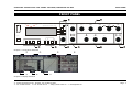
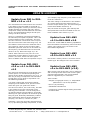
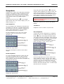
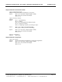
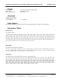
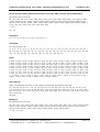
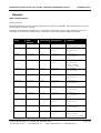
digital audio
weiss engineering ltd.
Florastrasse 42, 8610 Uster, Switzerland
+41 44 940 20 06 +41 44 940 22 14
http://www.weiss.ch / http://www.weiss-highend.com
GAMBIT
DS1-MK3
OPERATING MANUAL
Software Version: 0S: 3.0,
DSP: 3.0
Release Date:
May, 2008
digital audio
weiss engineering ltd.
Florastrasse 42, 8610 Uster, Switzerland
+41 44 940 20 06 +41 44 940 22 14
http://www.weiss.ch / http://www.weiss-highend.com
Authors: Andor Bariska, Daniel Weiss, Weiss Engineering LTD.
Weiss Engineering LTD. reserves the right to make changes to product specification or documentation without prior notice. Updated manuals and datasheets
are available at our website for downloading. Weiss Engineering LTD. makes no
warranty, representation or guarantee regarding the suitability of its products
for any particular purpose, nor does part of this manual, and specifically discalims any and all liability, including without limitation consequential or incidental
damages.
All rights reserved. No part of this publication may be reproduced or transmitted in any form or by any means, electronic or mechanical including photocopying, scanning or any information storage or retrieval system without the express prior written consent of the publisher.
© Copyright Weiss Engineering LTD., 2008.
OPERATING INSTRUCTIONS FOR GAMBIT DE-ESSER/COMPRESSOR DS1-MK3
FRONT PANEL
FRONT PANEL
menu
menu
DS1-MK3
gambit series
digital de-esser / compressor / limiter
over
over
11
2
2
bandwidth
release
delay
attack
release
fast
average
release
slow
off
bypass
gain / data
store
recall
A-B
copy
safe
M/S
ch1/ch2
ganged
frequency
soft-knee
threshold
ratio
max.
gain makeup
monitor
snapshots
Graphic 1: Front Panel Elements
Graphic 2: Display Elements
Weiss Engineering Ltd., Florastr. 42, CH-8610 Uster
+41 44 940 20 06 +41 44 940 22 14 http://www.weiss.ch
Page 3
[email protected]
OPERATING INSTRUCTIONS FOR GAMBIT DE-ESSER/COMPRESSOR DS1-MK3
FRONT PANEL
Front Panel Groups
The front panel of the DS1-MK3 offers several control and display features.
Control
Refer to Graphic 1: Front Panel Elements
- Menu- and softkeys
p. 7
- Snapshot keys
p. 19
- ganged / channel select keys
p. 16
- Gain / Data controller
p. 8
- Crossover controllers
p. 12
- Envelope follower controllers
p. 10
+
- Non-linear transfer curve controllers
p. 11
Display
Refer to Graphic 2: Display Elements
- Gain value
- Crossover setting (frequency selective mode only)
- Non-linear transfer curve and signal metering
- Status display
p. 7
- Peak limiter gain reduction meter
p. 8
- Envelope follower settings
p. 10
- Compressor gain reduction meters
p. 10
p. 8
p. 12
p. 11
Weiss Engineering Ltd., Florastr. 42, CH-8610 Uster
+41 44 940 20 06
+41 44 940 22 14
http://www.weiss.ch [email protected]
Page 4
OPERATING INSTRUCTIONS FOR GAMBIT DE-ESSER/COMPRESSOR DS1-MK3
INTRODUCTION
INTRODUCTION
Congratulations on purchasing the Weiss DS1-MK3 De-esser / Compressor !
This two channel digital De-esser / Compressor
features linear-phase crossover filters covering
the whole audio band. Thus the DS1-MK3 is not
just a De-esser but can also be used as band
selective or full band Compressor / Limiter. The
controls for the two channels can be ganged or
unganged (useful for M/S compression). Similarly, sidechain linking can be turned off.
Internal processing is either 88.2kHz (with 44.1
and 88.2kHz input) or 96kHz (with 48 or 96kHz
input) in DeEsser and in Compressor mode.
Double-precision up- and down-sampling units
within the DS1-MK3 result in negligible distortion and high transparency for absolutely clean
sound.
The non-linear segment can be adjusted from
1000:1 to 1:5, allowing every kind of dynamic
processing, from limiting to upward expansion
(for over-compressed signals). Put back a little
dynamics into that ultra-finalized mix!
An additional safety-limiter takes care of any
overs that are generated in DeEsser as well as in
Compressor mode.
This and the ability to remote control parameters and snapshots makes the DS1-MK3 the
perfect tool for the recording and mastering
engineer!
∗
Logarithmic graph of the transfer function
of the de-esser/compressor calculated in
real time
∗
Status display showing sampling frequency, channel status data handling, current workspace and snapshot number and
a resetable peak-hold and over-hold per
channel
∗
Parameter display (activated by touching
the knobs) showing all timing, level and
gain parameters
∗
Signal status LEDs, showing OVERs, range
of envelope signal and the status of the
release time comparator
Snapshots
∗
3 x 128 non-volatile snapshots where all
parameters are stored
∗
A-B workspaces for quick comparison between two settings
Remote Control
∗
Supports MIDI, RS-232 and RS-422 protocols
∗
24bit digital input, internal 40bit floatingpoint arithmetic, dithered output for 16bit,
20bit or 24bit wordlengths.
Standard MIDI Continuous Controllers for
parameter remote control (including overall gain)
∗
Snapshot automatization with MIDI Program Change Commands
∗
Transparent phase-linear crossover for
frequency selective compression
∗ MIDI Dump of Snapshots
∗
All parameters are immediately accessible
with instant feedback through LEDs and
the LC display.
Processing
∗
Display
∗
Standardised peak meters for compressorstage in- and output with peak hold
∗
Gain reduction meter with peak hold for
compressor and for safety-limiter each.
Weiss Engineering Ltd., Florastr. 42, CH-8610 Uster
+41 44 940 20 06
+41 44 940 22 14
http://www.weiss.ch [email protected]
Page 5
OPERATING INSTRUCTIONS FOR GAMBIT DE-ESSER/COMPRESSOR DS1-MK3
HISTORY
UPDATE
UPDATE HISTORY
Update from DS1 to DS1MK2 v1.0 or v1.1
The main difference between these two versions
is the ability of the DS1-MK2 to accept 88.2 /
96kHz input signals. Contrary to the DS1, where
double sampling processing was only used in
compressor mode, the DS1-MK2 now uses internal up- and downsampling stages and all processing is at 88.2 / 96 kHz.
There is a completely new feature available in
the DS1-MK2, the upward expander. This is the
logical extension of the compressor. Just turn
the ratio controller counterclock wise to experience this new sound. New scale range on p. 26.
The DeEsser section has been enhanced with a
new crossover, which covers the whole audio
bandwidth (the DS1 used 271 Hz as lowest cutoff frequency, the DS1-MK2 can now be tuned
down to 41 Hz). New scale range on p. 25.
And for those who like it hot, there is a new
peak limiter section added in series to the compressor / de-esser, which cuts down spikes
above 0.0dBFS. Read about its operation on p.8.
Update from DS1-MK2
v1.0 or v1.1 to DS1-MK2
v1.3
The main new enhancement is the parallel compressor option. To read about operating and
options of the parallel compressor, turn to p. 14.
This way of using a compressor was motivated
by Bob Katz, here is what he says about it on
the Mastering Webboard:
“You want a patch that compresses without
stomping on the attacks at all, preserves transients but gives you great inner detail? ...
You have one control, one control only, and that
is the output level of the compressor [gain
makeup], the ‘sidechain’. You can bring out inner details without losing breathing, and hardly
affecting the upper dynamics at all. Works great.
Not just great, absolutely fantastically. Fattens
bass instruments without causing breathing or
pumping. You name it, it works very well.
(for example) high frequency inner details at low
levels are enhanced. ”
The other change in architecture is the addition
of a second gain before the safety limiter, referred to as pre-limiter gain. The old overall gain
is also still available. Read on p. 8.
Also, the scales of the gain, gain makeup and
ratio parameters has been modified to suit customer feedback. New values on p. 26.
Update from DS1-MK2
v1.3 to DS1-MK2 v2.0
In the v2.0 version POW-R dithering capabilities
have been added. The dithering menu now has a
"setup" entry which gives you access to the
three POW-R algorithms.
Update from DS1-MK2
v2.0 to DS1-MK2 v2.1
New Feature: Safety Limiter is now also of auto
release type. No changes to the user interface.
Update from DS1-MK2
v2.x to DS1-MK3 (v3.0)
After several years of the DS1’s use in mastering
and recording studios world wide we have gathered and implemented a list of most wanted
features suggested by our customers.
These include:
- Ganged or unganged control, i.e. independent
parameters in L/R or M/S possible
- M/S or L/R processing
- Switchable sidechain link
- Continuously variable signal sensing from Peak
to 800ms RMS
Variations: Use it like the Dolby Spectral Enhancer, by split band [parallel] compression, so that
Weiss Engineering Ltd., Florastr. 42, CH-8610 Uster
+41 44 940 20 06
+41 44 940 22 14
http://www.weiss.ch [email protected]
Page 6
OPERATING INSTRUCTIONS FOR GAMBIT DE-ESSER/COMPRESSOR DS1-MK3
OPERATION
OPERATION
The following explanations assume that the de-esser/compressor is in power-up mode, i.e. no
menu is active. If a menu is active, press the “menu” key repeatedly until the status display
appears.
Status Display
Peak-Hold
The numeric peak value is measured relative to
0dBFS (digital full scale).
Use this value to set the optimum gain for a
specific session. Reset it for every session by
pressing key B twice.
Over-Hold
Whenever an over is encountered, the boxes to
the side of the peak-hold values are marked.
Graphic 3: Status Display
The status display consists of four groups
displaying audio signal properties and
information about the current state of the DS1MK3.
Channel Status Group (Key A)
Situated adjacent to key A, displays the following information:
∗
sampling frequency in kHz: “44.1”, “48”,
“88.2” or “96”.
∗
pre-emphasis: “E” appears if preemphasis is set (empty if not used)
∗
input → output channel status data format: “C” for consumer and “P” for professional
To change the output channel status data format, press key A and select format type or loop
through.
Peak Group (Key B)
Situated adjacent to key B, this group contains a
peak-hold and an over-hold for each channel. To
reset these values press key B twice.
The functions of the over-LED’s and the overhold both depend on the NUMBER OF
CONSECUTIVE OVER-SAMPLES setting. To adjust
this setting, press key B once. Use the gain/
data controller () to change the value, then
press “menu” to return to the status display.
This setting defines the number of consecutive
over-samples needed for an over-indication. To
indicate every over-sample, enter 1. If another
value is entered, you are still able to detect a
single over-sample with the peak-hold function.
Over-samples are defined as exceeding the
integer range. A full scale signal (0dBFS)
will not be treated as over.
Remote Group (Key C)
Situated adjacent to key C, displays remote
control protocol (“MIDI”, “RS 232” or “RS 422”),
channel (“1” - “16”) and status (on/ off, displayed with check box).
For setup see chapter Remote Control (p.21).
Weiss Engineering Ltd., Florastr. 42, CH-8610 Uster
+41 44 940 20 06
+41 44 940 22 14
http://www.weiss.ch [email protected]
Page 7
OPERATING INSTRUCTIONS FOR GAMBIT DE-ESSER/COMPRESSOR DS1-MK3
Snapshot Display (Key D)
OPERATION
Gain / Output Gain
Bottom line in the status display. Refer to this
for information on current workspace and snapshot. There are two workspaces (“A” and “B”) for
quick comparison of two de-esser/compressor
settings. A workspace can be stored to a snapshot for later use.
The number of the last recalled snapshot will be
displayed. If you change any value after the
recall, the “=” will change to “≠” to symbolise
that the workspace is not equal to the displayed
snapshot anymore.
For snapshot handling see chapter Snapshots
(p.19).
Dither Icon (Key D)
The dither icon is situated right next to key D
(see Graphic 3). If dither is off, the icon contains
the number “24“, the word length of the output
signal in bits. Turning dither on will produce
arrows above and below the new word length
number (“16“ or “20“). Additionally, if autoblacking is enabled, the bottom right corner of
the icon is inverted.
For details on dither refer to chapter Dither (p.
18).
There are two gains, one pre safety-limiter and
one post safety-limiter, as depicted in Graphic 4.
Output
Gain
Gain
from previous
processing
X
Safety
Limiter
Output
X
Graphic 4: Output section
When touching the gain controller (), the
required gain can be selected from a menu. To
change the output gain, press softkey D. If an
arrow appears inside the output gain window,
the Output Gain can be adjusted. Press the D
key again to control the pre-limiter gain which is
shown in the upper left corner of the display.
Both gains are bypassed when Bypass is active.
The value shown in
limiter gain.
is the setting of the pre-
The post-limiter output gain should be used to
set the maximum output level only (usually
0.0dB).
Safety Limiter
This feature is activated by pressing the “safe”
key. When the “safe” key is lit, the limiter is on.
Safety limiter activity can be monitored with the
second gain reduction meter below the “GAIN”
window ().
If the “safe” key is lit, overs will be limited by
this fast peak limiter. The parameters of the
limiter are fixed and cannot be adjusted.
However, the pre-limiter gain can be used to
drive the safety limiter.
Too much pre-limiter gain will result in distortion!
Weiss Engineering Ltd., Florastr. 42, CH-8610 Uster
+41 44 940 20 06
+41 44 940 22 14
http://www.weiss.ch [email protected]
Page 8
OPERATING INSTRUCTIONS FOR GAMBIT DE-ESSER/COMPRESSOR DS1-MK3
OPERATION
Compressor Parameters
Following is a detailed description of all parameters that can be adjusted in the compressor stage. Guidelines are given for settings (see also the factory presets), but optimal settings are usually programme
dependent, so experimenting and listening is inevitable for satisfying results.
Graphic 5 shows schematic and parameters of the DS1-MK3 compressor stage:
overall preview
delay
Input
audio signal
Delay
Output
x
gain control
signal
Mainchain
Envelope
Detection
attack
Non-Linear
Transfer Curve
release
fast
release
delay
release
slow
average
RMS
soft-knee
ratio
threshold
gain
makeup
Sidechain
Graphic 5: Compressor schematic
Delay
A typical compressor/limiter circuit measures
the audio signal and then generates the gain
reduction control signal. At the time the control
signal changes the gain, the programme material is already there, so the gain change occurs
too late. The result is overshoot and possible
subsequent distortion.
The DS1-MK3 uses a different method to generate the gain control signal: The audio passing
through the mainchain is delayed by a fixed
amount of time, determined by the „overall delay“. By branching the signal out of the delay
line, the sidechain „sees“ the signal before it
reaches the output, thus allowing look-ahead
compared to the mainchain. The resulting corrected output signal has no overshoots, no leading edge distortion or other side effects due to
timing lags in the sidechain.
The preview (the time the signal reaches the
sidechain ahead of the multiplier) cannot, of
course, exceed the overall delay.
The overall delay is the sum of the maximum
overall delay („Delay“ box in Graphic 5) and the
delay required for other signal processing (linear-phase filtering for up- and downsamplers).
Any snapshot value of the preview delay which
exceeds this maximum, is clipped to the maximum, because the overall delay is not stored in
the snapshots and therefore the preview delay in
any snapshot can exceed the currently selected
overall delay.
Setting overall delay: The overall delay is
adjusted by pressing the „menu“ key () then
selecting the „system“ and then the „overall
delay“ option. Use the gain / data controller
() to change the delay value. Maximum consequential preview time and delay in frames is
also displayed. Please note that during delay
Weiss Engineering Ltd., Florastr. 42, CH-8610 Uster
+41 44 940 20 06
+41 44 940 22 14
http://www.weiss.ch [email protected]
Page 9
OPERATING INSTRUCTIONS FOR GAMBIT DE-ESSER/COMPRESSOR DS1-MK3
OPERATION
change, audio is muted to avoid audio signal
cuts.
Graphic 6: System menu
Graphic 9: Envelope Parameters
Attack and Preview: The longer the attack
time, the more will the leading edge of fast transients pass by the gain reduction circuit unaltered (as in Graphic 9 during attack phase).
Very fast attack time settings such as 20µs, i.e.
one sample period, do catch every transient, but
may distort low frequencies. To utilise longer
attack times and still catch fast transients, use
preview.
Graphic 7: Overall Delay display
Setting preview: Touch either the „attack“ or
„release delay“ controller () to activate the
timing 1 window, then use the gain / data controller () to adjust preview time.
Release and Average: The input signal is
monitored with two different methods: peak
amplitude (*) and RMS value. The peak amplitude is the programme portion we don't perceive
as very loud, however which can easily cause
overloads. The RMS value of the programme
material we perceive as loudness. Its variations
contribute most to the dynamic range of the
audio.
The sidechain processor compares the two
measurements it obtained from the peaks and
the RMS. The ratio between the two determines
which time constant would be the appropriate
release, e.g. after short duration peak the faster
release will be applied during the release phase.
The time period over which the RMS value of the
programme material is averaged is set by the
"average" parameter. The effect of the average
parameter can best be studied on the gain re-
Graphic 8: Timing 1 window
Envelope Follower
The envelope follower parameter controllers are
in area . The purpose of the envelope follower
is to cause gradual gain changes, thus eliminating distortion. The current values are shown in
.
duction meter (). Fast "average" settings will
cause most of the gain reduction meter to move
very fast (depending on the "release fast" setting) , slower settings will just have the top part
of the gain reduction move fast, with the bottom
part depending on the "release slow" setting.
(*) Peak / RMS: In the DS1-MK3 the peak
measurement is supplemented with an RMS
measurement with variable averaging time. To
access the RMS detection timeconstant touch
Weiss Engineering Ltd., Florastr. 42, CH-8610 Uster
+41 44 940 20 06
+41 44 940 22 14
http://www.weiss.ch [email protected]
Page 10
OPERATING INSTRUCTIONS FOR GAMBIT DE-ESSER/COMPRESSOR DS1-MK3
OPERATION
the gain / data controller () which opens this
window:
Graphic 10: Gain / Data Knob menu
Hit Key B to assign the gain / data knob to the
RMS detection timeconstant. The left endstop of
this parameter switches the detection to peak
mode, as used in all previous DS1 versions.
Graphic 11: Timing 2 window
Release Delay: Normally the release phase
begins immediately after the programme material has fallen in level. The release delay determines how long the DS1-MK3 holds the current
level before entering release (see Graphic 9).
The resulting dynamic characteristic is very
smooth and avoids otherwise typical 'pumping'
effects. The ideal setting is programme dependent and experimentation may be necessary to
achieve the best combination of all dynamic
parameters.
Non-Linear Transfer Curve
The transfer curve parameter controllers are in
area
Graphic 12: Transfer Curve Parameters
Threshold: Sets the level which the envelope
signal has to reach before gain reduction is applied.
Ratio: Sets the slope of the segment above the
threshold. The ratio can be adjusted for compression or expansion, depending on the requirement. For full band expansion (e.g. to reintroduce dynamics into an over-compressed
signal), one will usually work with the gain
makeup set to maximum. This means that a
0.0dB input will be passed through without gain,
signals below the threshold will be reduced with
a constant gain (depending on threshold and
ratio setting, can be read from the display when
touching the gain makeup controller), and
signals between the threshold and 0.0dBFS get
expanded. For full band expansion, one will
typically have quite high thresholds (-1dB ... –
4dB), because of the resulting overall gain.
The expander can also be used in frequency
selective mode, for example to repair the effect
of a misused multi-band compressor – for this
purpose, the gain makeup can be set higher
than the calculated maximum setting, to
compensate for the overall gain that the
expander causes. This can potentially cause
overs (for loud signals in the expanded band), it
is therefore good practice to engage the safety
limiter (see below).
+. This part of the sidechain is re-
sponsible for the actual gain reduction () calculations. The detected signal envelope is compared with the transfer curve, the gain control
signal (see Graphic 5) is then adjusted accordingly if the envelope overshoots the transfer
curve.
Weiss Engineering Ltd., Florastr. 42, CH-8610 Uster
+41 44 940 20 06
+41 44 940 22 14
http://www.weiss.ch [email protected]
Page 11
OPERATING INSTRUCTIONS FOR GAMBIT DE-ESSER/COMPRESSOR DS1-MK3
OPERATION
The applied gain reduction from the compressor section is displayed in
.
Signal Meters: The meters in show the level
of the input (horizontally on top of the transfer
curve graph) and output of the compressor
stage (vertically to the right of the transfer
curve). Refer to Graphic 16 and 17 to see the
metering points.
Graphic 13: Threshold, Ratio, Softknee
Band Selective Mode vs. Full Range Mode
The expander can only amplify gain differences. This means that it cannot create a
dynamic signal if there was no initial gain
difference (as is the case in computer generated music or with extremely hardlimited mixes).
Soft-knee: Determines how much the knee is
rounded. The maximum setting (1.0) chooses a
curve that reaches from 0dBFS down to twice
the threshold value. This implies that if softknee is engaged the signal is already affected
even if its envelope lies below the threshold.
Gain makeup : Moves the whole transfer
curve up or down. In de-essing mode the gain
makeup is usually set between the minimum (10dB gain) and "off" (0dB gain) to actually attenuate the processed signal, while in compressor (full band) mode the transfer curve usually
gets to lie anywhere between "off" and "max",
according to the amount of loudness correction
one wants to apply.
The DS1-MK3 can be used in conjunction with a
frequency crossover (band selective mode) or
straight (full range mode).
How to change modes: Touch the centre frequency or bandwidth controller (). The softkeys become selection keys for the filter type:
highpass (Key A), bandpass (Key B), lowpass
(Key C) or bypass (Key D). In bypass the full
range mode (compressor) is selected. Any other
filter type engages the appropriate filter ahead
of the compressor stage.
Band Selective Mode (Graphic 16): In this
mode, a frequency crossover is put into the signal path, splitting it up into two or three bands,
depending on the filter type setting. One of the
bands is compressed, the other is delayed by
the same amount used as „delay“ in the compressor stage. This mode is completely transparent if no gain reduction is applied.
Once "max." is on, the transfer curve is attached
to 0dBFS for maximum possible gain. "max" is
engaged as soon as the curve reaches 0dBFS by
manipulating any combination of the above parameters, or by selecting "max" from the gain
makeup menu. This mode can be exited by
manually reducing the gain makeup or by selecting "off" from the gain makeup menu.
Graphic 15: Band Filter menu
Graphic 14: Gain Makeup display
Weiss Engineering Ltd., Florastr. 42, CH-8610 Uster
+41 44 940 20 06
+41 44 940 22 14
http://www.weiss.ch [email protected]
Page 12
OPERATING INSTRUCTIONS FOR GAMBIT DE-ESSER/COMPRESSOR DS1-MK3
Note, the input and output meters on the transfer graph () are connected after the crossover
and before the adder.
OPERATION
Full Range Mode (Graphic 17): In this mode
the compressor input meter is at the input of the
DS1-MK3. The crossover controllers and the
monitor key have no function.
filter- band- centre
type width frequency
Input
band
stop
+
Delay
Crossover
monitor
Output
Gain
Gain
band
pass
X
Comp.
input
meter
Safety
Limiter
output
meter
X
Output
peak / over
hold
Graphic 16: Band Selective Mode
input
meter
output
meter
peak / over
hold
Output
Gain
Gain
Input
Comp.
X
Safety
Limiter
X
Output
Graphic 17: Full Range Mode
Weiss Engineering Ltd., Florastr. 42, CH-8610 Uster
+41 44 940 20 06
+41 44 940 22 14
http://www.weiss.ch [email protected]
Page 13
OPERATING INSTRUCTIONS FOR GAMBIT DE-ESSER/COMPRESSOR DS1-MK3
OPERATION
Parallel Compressor
before limiting.
The DS1-MK3 can be used in parallel compression mode, where the compressed signal is
added to the straight signal.
Parallel band selective compression
(Graphic 20): To add even more subtle compression, the compressed signal can be filtered
before compression. Using the monitor function,
one can listen to the filtered signal for optimal
crossover setup.
How to activate parallel compression: Touch
the gain / data controller (). In the menu that
appears, mark the checkbox with softkey A.
When using parallel compression, the DS1-MK3
is able to run in frequency selective or in full
band mode.
Why parallel compression?
Read this quote from Bob Katz from the Mastering Webboard:
“You want a patch that compresses without
input
meter
output
meter
Input
Comp.
peak / over
hold
+
Graphic 19: Parallel Compression on/off (Key A)
Parallel full band compression: As can be
seen in the schematic (Graphic 18), the input
signal and the compressed signal are added
together. The gain makeup value can be used to
control the amount of compressed signal. The
pre-limiter gain can be used to scale the mix
input
meter
Crossover
band
pass
x
Output
stomping on the attacks at all, preserves transients but gives you great inner detail? ...
Graphic 18: Parallel Full Range Compression
Input
Output
Gain
Pre-Limiter
Gain
Safety
x
Limiter
You have one control, one control only, and that
is the output level of the compressor [gain
makeup], the ‘sidechain’. You can bring out inner details without losing breathing, and hardly
affecting the upper dynamics at all. Works great.
Not just great, absolutely fantastically. Fattens
bass instruments without causing breathing or
pumping. You name it, it works very well.
Variations: Use it like the Dolby Spectral Enhancer, by split band [parallel] compression, so that
(for example) high frequency inner details at low
levels are enhanced. ” The last paragraph refers
to parallel band selective compression (crossover in highpass mode).
Graphic 20: Parallel band selective compression
output
meter
Comp.
peak / over
hold
+
Pre-Limiter
Gain
Safety
x
Limiter
Weiss Engineering Ltd., Florastr. 42, CH-8610 Uster
+41 44 940 20 06
+41 44 940 22 14
http://www.weiss.ch [email protected]
Output
Gain
x
Output
Page 14
OPERATING INSTRUCTIONS FOR GAMBIT DE-ESSER/COMPRESSOR DS1-MK3
OPERATION
Starting point for parallel compression:
Set the threshold for -50 dBFS, ratio to 2.5:1,
attack to the fastest (microseconds), release to
mid, around 250-300 ms (adjust to taste if you
hear breathing or pumping). The makeup gain
governs the amount of compression.
Graphic 21: effect of parallel compression
Graphic 21 shows the effect of Parallel Compression on the transfer curve (upper graph). Lower
levels are raised while higher levels are not
much affected.
Weiss Engineering Ltd., Florastr. 42, CH-8610 Uster
+41 44 940 20 06
+41 44 940 22 14
http://www.weiss.ch [email protected]
Page 15
OPERATING INSTRUCTIONS FOR GAMBIT DE-ESSER/COMPRESSOR DS1-MK3
Ganged /Unganged
The DS1-MK3 allows for independent parameter
settings in channels 1 and 2 (). If the ganged
key is lit, both channels operate with the same
parameter set.
If the ganged key is not lit, the two channels can
operate with different parameters. The CH1/CH2
/ M/S key assigns the knobs and the display to
the appropriate channel, i.e. key not lit assigns
CH1 or M and key lit assigns CH2 or S.
In ganged mode the CH1/CH2 M/S key becomes
a special function, it then can be used as a A/B
key in that either CH1 settings are applied to
both channels or the CH2 settings are applied to
both channels.
The copy menu (copy key) allows to copy CH1
into CH2 parameters or vice versa in order to
have the same parameters in the two channels
to start with.
OPERATION
The “Compressor” block can again work in full
band mode or in band selective mode, independently in the two channels. I.e. it is possible
to process e.g. the S signal in full band mode
and have the M signal processed in band selective mode for de-essing.
The parallel compression again works around the
“Compressor” block. Parallel compression can be
switched on independently in the two channels.
Input
L
R
M/S Encoder
M
S
input
meter
Compressor
M/S Mode,
Sidechain Link
output meter,
Monitor
The DS1-MK3 can be switched to M/S (Mid /
Side) mode. To do that press the menu key, the
following menu opens up:
Gain
Safety
Limiter
M/S decoder
L
Graphic 22: M/S Mode and Sidechain Link
R
Key A selects M/S Mode on / off (box checked
means M/S mode engaged) while Key B selects
the sidechain link on / off (box checked means
sidechain linked). In M/S mode it usually is preferable to set the channels unganged and the
sidechain unlinked.
Graphic 23 shows the block digram of the DS1MK3 when in M/S mode. Note the positions of
the M/S encoder and decoder. With the “Gain”
controls it is possible to change the balance between M and S, while the “Output Gain” controls
are arranged after the M/S to L/R conversion.
Output
Gain
peak/over
hold
L
R
Output
Graphic 23: Block diagram in M/S mode
Weiss Engineering Ltd., Florastr. 42, CH-8610 Uster
+41 44 940 20 06
+41 44 940 22 14
http://www.weiss.ch [email protected]
Page 16
OPERATING INSTRUCTIONS FOR GAMBIT DE-ESSER/COMPRESSOR DS1-MK3
OPERATION
Monitor Key
In band selective mode pressing the “monitor”
key allows you to listen directly to the processed band, ideal for zooming in on offending
material and listening to the effect of the compressor stage.
See Graphic 23 above for the Monitor output
position.
The Monitor output works as follows:
DS1-MK3 in ganged mode:
The stereo signal is fed forward to the output. If
the band selective mode is selected, only the
active band is fed to the output.
DS1-MK3 in unganged mode:
The currently selected channel (CH1 or CH2 or M
or S) is fed to both L and R outputs. This allows
for instance to listen to the S signal only in order
to adust the compressor optimally.
If monitor is active, the output peak hold
and the over detection run on the monitor
signal, not on the main output.
Weiss Engineering Ltd., Florastr. 42, CH-8610 Uster
+41 44 940 20 06
+41 44 940 22 14
http://www.weiss.ch [email protected]
Page 17
OPERATING INSTRUCTIONS FOR GAMBIT DE-ESSER/COMPRESSOR DS1-MK3
OPERATION
Factory Presets
The DS1-MK3 has easily accessible factory presets for a quick setup which can then be refined
and adapted to the programme being processed.
These factory presets are grouped according to
their function:
De-Esser: Four applications for high-frequency
transients removal. Adjust threshold and crossover frequency as required.
Limiter: Three settings for loudness maximising
- experiment with the transfer curve parameters
for a programme optimised result. The last setting uses the crossover to select the low-band
and applies a small gain, hence „bass boost“.
Dither
The DS1-MK3 is able to apply POW-R type dither
algorithms to avoid distortion when requantizing from 24bit to 16bit or 20bit output
word length (see TECHNICAL DATA for dither
specifications).
To toggle dither on/off, press key D twice. To
see dither status refer to the status display (,
see Status Display p. 7).
Word Length
To set output word length, press key D and select the appropriate wordlength.
[More factory presets are in preparation]
Setup
To access the factory presets press the “menu”
key then “snapshots” and then the “presets”
key.
Press key D then chose the setup menu. This
leads to the menu where the type of POW-R
dither can be chosen (see TECHNICAL DATA for
dither specifications). Also selectable is:
Auto-Blacking
If auto-blacking is activated by marking the “0
IN 0 OUT“ option, dither will be turned off if
the input signal is zero As soon as the input
signal changes, dither will be turned on again.
This ensures that pauses between programmes
are still digital zero, even if dither is activated.
Graphic 24: Snapshots menu
Weiss Engineering Ltd., Florastr. 42, CH-8610 Uster
+41 44 940 20 06
+41 44 940 22 14
http://www.weiss.ch [email protected]
Page 18
OPERATING INSTRUCTIONS FOR GAMBIT DE-ESSER/COMPRESSOR DS1-MK3
Snapshots
Snapshots are copies of the DS1-MK3 parameter
settings. This allows recalling complete set-ups
including all parameters and controls settings.
Snapshots can be recalled from the front panel
or by remote control (e.g. MIDI Program
Change).
Snapshot access keys are in
. To see work-
space status refer to the status display (, see
Status Display p. 7).
OPERATION
Using the gain/ data controller () enter the
number of the snapshot you want to recall. The
graph of the snapshot will be displayed. However, the audio signal is not affected if the “Preview” option is marked. Once you have found
the snapshot, press key D to restore it.
If the “Preview” option is not marked, the
snapshots will be recalled as soon as you
enter a new number.
Press the “recall” key to return to the status
display.
A-B Comparison
You can compare two settings by using the two
workspaces “A” and “B”. To toggle between the
two press the “A-B” key. Restore a snapshot or
simply adjust parameters in one workspace,
then switch to the other to compare.
“Recall # 0”
Snapshot 0 can be used for a quick reset.
Store Snapshots
To copy workspace “A” to “B” or vice versa,
press the “copy” key and select an option
(Graphic 25).
To store the current workspace to a snapshot,
press the “store” key. With the gain/ data controller () enter the snapshot number where
you want to store the workspace, then press key
D. Snapshots can be prevented from accidental
erasure by marking the “Safe” option.
A setting can be stored to multiple snapshots.
Press “To Range” in the “store” menu.
Graphic 25: Copy menu
The active workspace is shown in the status
display.
Recall Snapshots
To recall a snapshot press the “recall” key. Notice that the snapshot will be copied into the
active workspace. If you do not want to lose
these settings, switch to the other workspace by
pressing the “A-B” key.
Graphic 27: Store To Range menu
Press the adjacent keys to select “Start” and
“End” snapshot number, use the “gain/ data”
encoder to enter a value (Graphic 27). Pressing
“Execute” will store the setting from the displayed workspace (“A” or “B”) to all snapshots
between the Start and End value. A “Safe” snapshot will not be overwritten.
Graphic 26: Recall menu
Weiss Engineering Ltd., Florastr. 42, CH-8610 Uster
+41 44 940 20 06
+41 44 940 22 14
http://www.weiss.ch [email protected]
Page 19
OPERATING INSTRUCTIONS FOR GAMBIT DE-ESSER/COMPRESSOR DS1-MK3
Backup Snapshots
All 128 snapshots can be transferred to another
internal non-volatile memory area for later reference. There is enough memory for two complete snapshot sets to be backed up.
Press the “menu” key () then choose the
“Snapshots” and then the “Backup” option to
arrive at the backup display (Graphic 28).
OPERATION
When dumping to a MIDI-sequencer, make sure
that the sequencer is not sending or receiving
data other than the snapshot dump.
Certain sequencers are not capable of handling the amount of data output by the
DS1-MK3 and might crash during or after
the dump process.
To initiate a dump, press the “menu” key then
choose the “Snapshot” and then the “Dump”
option. Start the recording process on the sequencer, then press “Transmit”. This releases
the dump to the sequencer.
Loading Snapshots
Graphic 28: Backup display
Select “Create #1” to save the current snapshots
to bank 1. Select “Restore #1” to overwrite the
current snapshots with bank 1 (ditto for bank 2).
A backup will overwrite “safe” snapshots.
To load a snapshot dump from sequencer, simply play the dump sequence. The DS1-MK3 will
automatically switch into receive mode and display statistics about the snapshots it’s receiving.
If the transmission was OK, the program
switches back to normal mode. Upon error, you
have to manually switch back to normal mode.
When playing back the dump sequence,
always use the same speed as when the
sequence was recorded.
Reset all Snapshots
To reinstall the factory snapshots press the
“menu” key then “snapshots” and then the “Reset all” option. This will reset the current snapshots. The snapshots that have been backed up
are preserved.
Note, the DS1 or DS1-MK2 snapshots are
not compatible with the DS1-MK3 snapshots.
A program to convert the DS1-MK2 to DS1MK3 snapshots is in preparation.
Graphic 29: Snapshots menu
Graphic 30: Dumping Snapshots
Dump Snapshots
The settings of all 128 snapshots can be dumped
to a remote control port to be stored externally.
Please make sure that you have connected everything correctly and that the proper remote
control port is activated (see chapter Remote
Control for setup).
Weiss Engineering Ltd., Florastr. 42, CH-8610 Uster
+41 44 940 20 06
+41 44 940 22 14
http://www.weiss.ch [email protected]
Page 20
OPERATING INSTRUCTIONS FOR GAMBIT DE-ESSER/COMPRESSOR DS1-MK3
Meter Resolution
The transfer graph and the compressor peak
meters () work with different resolutions to
accommodate signals with a wide dynamic
range.
The resolution for the peak meters and transfer
graph can be set in fixed steps of -20dB, -40dB
and -80dB, or alternatively, to auto. In auto
mode, the display switches to the next step as
soon as the transfer graph falls below the current window. The peak meters resolution is always the same as the transfer graph’s.
The same principle applies to the gain reduction
meters of the compressor () and the safety
limiter (
).
To adjust gain reduction or peak meter resolution, press the „menu“ key (), then chose
“system” and then press the „display“ softkey.
Then use keys A and B to select either „gain
reduction“ or „curve“ to change the resolution of
the corresponding graphs. Use the gain / data
controller () to alter values.
LCD Contrast
OPERATION
While bypass is active (key is lit), the DS1-MK3
works in preview mode. This allows you to
change parameters without actually affecting the
audio signal.
Remote Control
All band parameters as well as control settings
can be set externally.
To see remote control status refer to the status
display (, see Status Display p. 7).
Protocol
To select a remote control protocol, press key C
from the status display menu. Select either “RS
232”, “RS 422” or “MIDI”. This will determine
which port at the rear of the DS1-MK3 is active.
The other inactive ports will be ignored.
Press the “menu” key to return to the status
display if you do not want to change remote on/
off status.
When selecting a port other than MIDI you have
to specify the baud rate. Refer to the remote
control software manual for correct settings. The
set baud rate is displayed to ensure proper setup.
Channel
To change the display contrast, press the
“menu” key (), then “system, then “display”.
Press key D to activate „LCD Contrast“. Adjust
contrast with the gain / data encoder.
To change the remote control channel number,
press key C (adjacent to the remote control
field). Use the gain / data controller () to
select a value between 1 and 16. Press the
“menu” key to return to the status display. Omni
mode (listening on all channels simultaneously)
is not supported.
On/ Off
To enable or disable remote control, press key C
(adjacent to the remote control field). Press it
again to toggle the “ON/ OFF”-value.
While remote control is off, data will still be sent
to the selected port. Also, the MIDI THRU output
will always mirror the MIDI IN input data regardless of “ON/ OFF” or protocol status.
Graphic 31: Display menu
Bypass
The DS1-MK3 can be completely bypassed with
the green “bypass” key below the mains switch.
If the “bypass” key is lit, the DS1-MK3 is absolutely transparent, making the output signal bit
equal to the input signal. However, the overall
delay (see chapter Delay) is still active.
Weiss Engineering Ltd., Florastr. 42, CH-8610 Uster
+41 44 940 20 06
+41 44 940 22 14
http://www.weiss.ch [email protected]
Page 21
OPERATING INSTRUCTIONS FOR GAMBIT DE-ESSER/COMPRESSOR DS1-MK3
OPERATION
Software Information
Press the “menu” key (), then select the “System” and the “About” option. This displays a
screen with all the relevant information on your
DS1-MK3 and how to reach us. Have this page
ready when you want to report a problem.
Graphic 32: System menu
Graphic 33: About screen
Weiss Engineering Ltd., Florastr. 42, CH-8610 Uster
+41 44 940 20 06
+41 44 940 22 14
http://www.weiss.ch [email protected]
Page 22
OPERATING INSTRUCTIONS FOR GAMBIT DE-ESSER/COMPRESSOR DS1-MK3
TECHNICAL DATA
TECHNICAL DATA
AES/EBU Input
Sampling Frequencies:
Maximum Input Wordlength:
Channel Status Data:
Channel Status Bits
forwarded to AES/EBU output:
Connector:
44.1 kHz, 48.0 kHz, 88.2 kHz or 96kHz
24 Bits
Input accepts professional or consumer format.
see table below
XLR female
AES/EBU Output
Sampling Frequencies:
Output Wordlength:
Connector:
44.1 kHz, 48.0 kHz, 88.2 kHz or 96kHz
24 Bits
XLR male
AES/EBU Channel Status Data
The DS1-MK3 allows to convert the incoming Channel Status Data as follows:
∗
From Consumer to Professional
∗
From Professional to Consumer
∗
Transparent mode, i.e. Channel Status Data is fed forward to the output without any conversion
(one exception, see below)
The following tables describe how the Channel Status Data bits are generated in the various
conversion modes.
Output selected: Consumer format.
Input: Consumer format.
Output:
All bits fed forward (transparent), except for:
Byte 1:
Bits 0..6: 0000000 (category code general)
Bit 7: 1 (original)
Input: Professional format.
Output:
Byte 0:
Bit 0: 0 (consumer)
Bit 1: 0 (audio)
Bit 2: 1 (copy allowed)
Bits 3,4: Preemphasis according to input
Bit 5: 0 (2 channel mode)
Bits 6,7: 00 (Mode 0)
Byte 1:
Bits 0..6: 0000000 (category code general)
Bit 7: 1 (original)
Byte 2:
Bits 0,1,2,3: Sampling Frequency according to input
Bits 4,5: 00 (accuracy grade II)
Bits 6,7: 00
Bytes 3..23:
reserved bytes
Weiss Engineering Ltd., Florastr. 42, CH-8610 Uster
+41 44 940 20 06
+41 44 940 22 14
http://www.weiss.ch [email protected]
Page 23
OPERATING INSTRUCTIONS FOR GAMBIT DE-ESSER/COMPRESSOR DS1-MK3
TECHNICAL DATA
Output selected: Professional format.
Input: Professional format.
Output: All bits fed forward (transparent), except for:
Byte 2:
Bits 0,1,2: 001 (max. sample length= 24bit)
Bits 3,4,5: 101 (24 bit word length)
Bits 6,7: 00
Input: Consumer format.
Output:
Byte 0:
Bit 0: 1 (professional)
Bit 1: 0 (audio)
Bits 2,3,4: Preemphasis according to input
Bit 5: 0 (source fs locked)
Bits 6,7: Sampling Frequency according to input
Byte 1:
Bits 0,1,2,3: 0001 (two channel mode)
Bits 4,5,6,7: 0000 (no user bit encoding)
Byte 2:
Bits 0,1,2: 001 (max. sample length= 24bit)
Bits 3,4,5: 101 (24 bit word length)
Bits 6,7: 00
Bytes 3..12: All bits 0
Byte 23:
CRCC byte
Output selected: Transparent.
Input: Any format.
Output:
All bits fed forward (transparent), except if not bypassed:
Byte 2:
Bits 0,1,2: 001 (max. sample length= 24bit)
Bits 3,4,5: 101 (24 bit word length)
Bits 6,7: 00
Weiss Engineering Ltd., Florastr. 42, CH-8610 Uster
+41 44 940 20 06
+41 44 940 22 14
http://www.weiss.ch [email protected]
Page 24
OPERATING INSTRUCTIONS FOR GAMBIT DE-ESSER/COMPRESSOR DS1-MK3
TECHNICAL DATA
Power
Mains Voltage:
Fuse rating:
Power Consumption:
110 / 220 Volts with voltage selector
500 mA slow blow
40VA max
Overload
Number of consecutive
over-samples to cause
“over” display:
1..16 settable
Peak Meters
Peak meters timing for compressor input and output stage adhere to AES recommendations.
Parameter Table
Overall Gain
All numbers in dB:
-∞
∞, -80.0, -75.0, -70.0, -65.0, -60.0, -55.0. -50.0, -45.0, -40.0, -35.0, -30.0, -28.0, -26.0, -24.0, -22.0,
-20.0, -18.0, -16.0, -14.0, -12.0, -10.0, -9.5, -9.0, -8.5, -8.0, -7.5, -7.0, -6.5, -6.0, -5.8, -5.6, -5.4, 5.2, -5.0, -4.8, -4.6, -4.4, -4.2, -4.0, -3.8, -3.6, -3.4, -3.2, -3.0, -2.9, -2.8, -2.7, -2.6, -2.5, -2.4, -2.3, 2.2, -2.1, -2.0, -1.9, -1.8, -1.7, -1.6, -1.5, -1.4, -1.3, -1.2, -1.1, -1.0, -0.9, -0.8, -0.7, -0.6, -0.5, -0.4, 0.3, -0.2, -0.1, 0.0, 0.1, 0.2, 0.3, 0.4, 0.5, 0.6, 0.7, 0.8, 0.9, 1.0, 1.1, 1.2, 1.3, 1.4, 1.5, 1.6, 1.7, 1.8,
1.9, 2.0, 2.1, 2.2, 2.3, 2.4, 2.5, 2.6, 2.7, 2.8, 2.9, 3.0, 3.2, 3.4, 3.6, 3.8, 4.0, 4.2, 4.4, 4.6, 4.8, 5.0,
5.2, 5.4, 5.6, 5.8, 6.0, 6.5, 7.0, 7.5, 8.0, 8.5, 9.0, 9.5, 10.0
Bandwidth
All numbers are fractions of octaves:
1/6, 1/3, ½, 2/3, 5/6, 1, 11/6, 1 1/3, 1 ½, 1 2/3, 1 5/6, 2, 2 1/6, 2 1/3, 2 ½, 2 2/3, 2 5/6, 3, 3 1/6, 3
1/3, 3 ½, 3 2/3, 3 5/6, 4, 4 1/6, 4 1/3, 4 ½, 4 2/3, 4 5/6, 5, 5 1/6, 5 1/3, 5 ½, 5 2/3, 5 5/6, 6, 6 1/6, 6
1/3, 6 ½, 6 2/3, 6 5/6, 7, 7 1/6, 7 1/3, 7 ½, 7 2/3, 7 5/6, 8.
Frequency
All numbers are Hertz and are either center or cutoff frequency:
41, 44, 46, 49, 52, 55, 58, 62, 65, 69, 73, 78, 82, 87, 92, 98, 104, 110, 117, 123, 131, 139, 147, 156,
165, 175, 185, 196, 208, 220, 277, 294, 311, 330, 349, 370, 392, 415, 440, 466, 494, 523, 554, 587,
622, 659, 698, 740, 784, 831, 880, 932, 988, 1050, 1110, 1170, 1240, 1320, 1400, 1480, 1570, 1660,
1760, 1860, 1980, 2090, 2220, 2350, 2490, 2640, 2790, 2960, 3140, 3320, 3520, 3730, 3950, 4190,
4430, 4700, 4980, 5270, 5590, 5920, 6270, 6640, 7040, 7460, 7900, 8370, 8870, 9400, 9960, 10500,
11200, 11800, 12500, 13300, 14100, 14900, 15800, 16700, 17700
Weiss Engineering Ltd., Florastr. 42, CH-8610 Uster
+41 44 940 20 06
+41 44 940 22 14
http://www.weiss.ch [email protected]
Page 25
OPERATING INSTRUCTIONS FOR GAMBIT DE-ESSER/COMPRESSOR DS1-MK3
TECHNICAL DATA
Attack, Release Delay, Release Fast & Slow, Average, RMS, Preview (when applicable):
All numbers are in seconds:
20µ, 40µ, 60µ, 80µ, 100µ, 125µ, 160µ, 200µ, 250µ, 315µ, 400µ, 500µ, 630µ, 800µ, 1m, 1.25m, 1.60m,
2.00m, 2.50m, 3.15m, 4.00m, 5.00m, 6.30m, 8.00m, 10.0m, 12.5m, 16.0m, 20.0m, 25.0m, 31.5m,
40.0m, 50.0m, 63.0m, 80.0m, 100m, 125m, 160m, 200m, 250m, 315m, 400m, 500m, 630m, 800m, 1,
1.25, 1.60, 2.00, 2.50, 3.15, 4.00, 5.00, 6.30, 8.00
µ = 10-6
m = 10-3
Soft-knee:
0.0, 0.1, 0.2, 0.3, 0.4, 0.5, 0.6, 0.7, 0.8, 0.9, 1.0
Threshold:
All numbers are in dB:
0, -1, -2, -3, -4, -5, -6, -7, -8, -9, -10, -11, -12, -13, -14, -15, -16, -17, -18, -19, -20, -21, -22, -23, 24, -25, -26, -27, -28, -29, -30, -31, -32, -33, -34, -35, -36, -37, -38, -39, -40, -41, -42, -43, -44, -45,
-46, -47, -48, -49, -50, -51, -52, -53, -54, -55, -56, -57, -58, -59, -60
Ratio:
1:5.00, 1:4.95, 1:4.90, 1:4.85, 1:4.80, 1:4.75, 1:4.70, 1:4.65, 1:4.60, 1:4.55, 1:4.50, 1:4.45, 1:4.40,
1:4.35, 1:4.30, 1:4.25, 1:4.20, 1:4.15, 1:4.10, 1:4.05, 1:4.00, 1:3.95, 1:3.90, 1:3.85, 1:3.80, 1:3.75,
1:3.70, 1:3.65, 1:3.60, 1:3.55, 1:3.50, 1:3.45, 1:3.40, 1:3.35, 1:3.30, 1:3.25, 1:3.20, 1:3.15, 1:3.10,
1:3.05, 1:3.00, 1:2.95, 1:2.90, 1:2.85, 1:2.80, 1:2.75, 1:2.70, 1:2.65, 1:2.60, 1:2.55, 1:2.50, 1:2.45,
1:2.40, 1:2.35, 1:2.30, 1:2.25, 1:2.20, 1:2.15, 1:2.10, 1:2.05, 1:2.00, 1:1.95, 1:1.90, 1:1.85, 1:1.80,
1:1.75, 1:1.70, 1:1.65, 1:1.60, 1:1.55, 1:1.50, 1:1.45, 1:1.40, 1:1.35, 1:1.30, 1:1.29, 1:1.28, 1:1.27,
1:1.26, 1:1.25, 1:1.24, 1:1.23, 1:1.22, 1:1.21, 1:1.20, 1:1.19, 1:1.18, 1:1.17, 1:1.16, 1:1.15, 1:1.14,
1:1.13, 1:1.12, 1:1.11, 1:1.10, 1:1.09, 1:1.08, 1:1.07, 1:1.06, 1:1.05, 1:1.04, 1:1.03, 1:1.02, 1:1.01,
1 : 1, 1.05:1, 1.11:1, 1.17:1, 1.25:1, 1.33:1, 1.43:1, 1.54:1, 1.67:1, 1.81:1, 2.00:1, 2.22:1, 2.50:1,
2.86:1, 3.33:1, 4.00:1, 5.00:1, 6.66:1, 10.0:1, 20.0:1, 1000:1
Gain Makeup:
Scale is symmetrical around 0.0, only positive values listed. All numbers are in dB:
0.0, 0.2, 0.4, 0.6, 0.8, 1.0, 1.2, 1.4, 1.6, 1.8, 2.0, 2.2, 2.4, 2.6, 2.8, 3.0, 3.2, 3.4, 3.6, 3.8, 4.0, 4.2,
4.4, 4.6, 4.8, 5.0, 5.2, 5.4, 5.6, 5.8, 6.0, 6.5, 7.0, 7.5, 8.0, 8.5, 9.0, 9.5, 10.0, 10.5, 11.0, 12.0, 13.0,
14.0, 15.0, 16.0, 17.0, 18.0, 19.0, 20.0, 22.0, 24.0, 26.0, 28.0, 30.0, 32.0, 34.0, 36.0, 38.0, 40.0, 45.0,
50.0, 55.0, 60.0
off, max.
RMS time:
All numbers are in seconds:
40µ, 60µ, 80µ, 100µ, 125µ, 160µ, 200µ, 250µ, 315µ, 400µ, 500µ, 630µ, 800µ, 1m, 1.25m, 1.60m, 2.00m,
2.50m, 3.15m, 4.00m, 5.00m, 6.30m, 8.00m, 10.0m, 12.5m, 16.0m, 20.0m, 25.0m, 31.5m, 40.0m,
50.0m, 63.0m, 80.0m, 100m, 125m, 160m, 200m, 250m, 315m, 400m, 500m.
µ = 10-6, m = 10-3
Weiss Engineering Ltd., Florastr. 42, CH-8610 Uster
+41 44 940 20 06
+41 44 940 22 14
http://www.weiss.ch [email protected]
Page 26
OPERATING INSTRUCTIONS FOR GAMBIT DE-ESSER/COMPRESSOR DS1-MK3
TECHNICAL DATA
Dither
Dithering algorithm is implemented using the POW-R set of algorithms. Graph 34 shows the three algorithms at 44.1kHz and 88.2kHz sampling rates each.
Graph 34: Output spectrum with 80dBFS / 1kHz sine wave, dithered to 16 Bits, using the three POW-R
algorithms at 44.1kHz and 88.2kHz respectively
Weiss Engineering Ltd., Florastr. 42, CH-8610 Uster
+41 44 940 20 06
+41 44 940 22 14
http://www.weiss.ch [email protected]
Page 27
OPERATING INSTRUCTIONS FOR GAMBIT DE-ESSER/COMPRESSOR DS1-MK3
TECHNICAL DATA
Remote
MIDI Implementation
System Inclusive
All band parameters plus the controls parameters are remote controllable. Each parameter has its corresponding MIDI controller number.
According to the different parameters, the controllers are limited in their range. Invalid values are replaced by the maximum allowable value. Following is a list of the supported MIDI commands:
Action
MIDI
Message
Status Byte
Data Byte(s)
Comment
Restore Snapshot
Program Change
1100 cccc
0ppp pppp
(cccc) Channel No.
Center Frequency 1
Control Change
1011 cccc
00000000 ($00)
(cccc) Channel No.
0vvv vvvv
(vvvvvvv) New Value:
00000001($01)
(cccc) Channel No.
(ppppppp) New Prog No: 0 - 127
0 – 105
Bandwidth 1
Control Change
1011 cccc
0vvv vvvv
(vvvvvvv) New Value:
0 - 48
Filter Mode 1
Control Change
1011 cccc
00000010 ($02)
0vvv vvvv
(cccc) Channel No.
(vvvvvvv) New Value:
0= limiter, 1= Bandpass,
2 = Lowpass, 3 = Hipass
Preview Delay 1
Control Change
1011 cccc
00000011 ($03)
0vvv vvvv
(cccc) Channel No.
(vvvvvvv) New Value:
0 - 32
Attack 1
Control Change
1011 cccc
00000100 ($04)
(cccc) Channel No.
0vvv vvvv
(vvvvvvv) New Value:
00000101 ($05)
(cccc) Channel No.
0 - 43
Release Delay 1
Control Change
1011 cccc
0vvv vvvv
(vvvvvvv) New Value:
0 - 53
Release Fast 1
Control Change
1011 cccc
00000110 ($06)
0vvv vvvv
(cccc) Channel No.
(vvvvvvv) New Value:
0 - 53
Average 1
Control Change
1011 cccc
00000111 ($07)
(cccc) Channel No.
0vvv vvvv
(vvvvvvv) New Value:
00001000 ($08)
(cccc) Channel No.
0vvv vvvv
(vvvvvvv) New Value:
00001001 ($09)
(cccc) Channel No.
0 - 53
Release Slow 1
Control Change
1011 cccc
0 - 53
Soft Knee 1
Control Change
1011 cccc
0vvv vvvv
(vvvvvvv) New Value:
0 - 10
Gain Makeup Mode 1
Control Change
1011 cccc
00001010 ($0A)
0vvv vvvv
(cccc) Channel No.
(vvvvvvv) New Value:
0= off, 1 = manual, 2= maximum
Weiss Engineering Ltd., Florastr. 42, CH-8610 Uster
+41 44 940 20 06
+41 44 940 22 14
http://www.weiss.ch [email protected]
Page 28
OPERATING INSTRUCTIONS FOR GAMBIT DE-ESSER/COMPRESSOR DS1-MK3
Ratio 1
Control Change
1011 cccc
TECHNICAL DATA
00001011 ($0B)
(cccc) Channel No.
0vvv vvvv
(vvvvvvv) New Value:
0 - 124
Threshold 1
Control Change
1011 cccc
00001100 ($0C)
0vvv vvvv
(cccc) Channel No.
(vvvvvvv) New Value:
0 - 60
Gain Makeup 1
Control Change
1011 cccc
00001101 ($0D)
(cccc) Channel No.
0vvv vvvv
(vvvvvvv) New Value:
0 - 126
Gain 1
Control Change
1011 cccc
00001110 ($0E)
(cccc) Channel No.
0vvv vvvv
(vvvvvvv) New Value:
0 – 127
Output Gain 1
Control Change
1011 cccc
00001111 ($0F)
0vvv vvvv
(cccc) Channel No.
(vvvvvvv) New Value:
0 – 127
Parallel Mode 1
Control Change
1011 cccc
00010000 ($10)
0vvv vvvv
(cccc) Channel No.
(vvvvvvv) New Value:
0–1
RMS time 1
Control Change
1011 cccc
00010000 ($11)
(cccc) Channel No.
0vvv vvvv
(vvvvvvv) New Value:
00000000 ($12)
(cccc) Channel No.
0 – 41
Center Frequency 2
Control Change
1011 cccc
0vvv vvvv
(vvvvvvv) New Value:
0 – 105
Bandwidth 2
Control Change
1011 cccc
00000001($13)
0vvv vvvv
(cccc) Channel No.
(vvvvvvv) New Value:
0 - 48
Filter Mode 2
Control Change
1011 cccc
00000010 ($14)
(cccc) Channel No.
0vvv vvvv
(vvvvvvv) New Value:
0= limiter, 1= Bandpass,
2 = Lowpass, 3 = Hipass
Preview Delay 2
Control Change
1011 cccc
00000011 ($15)
(cccc) Channel No.
0vvv vvvv
(vvvvvvv) New Value:
0 - 32
Attack 2
Control Change
1011 cccc
00000100 ($16)
(cccc) Channel No.
0vvv vvvv
(vvvvvvv) New Value:
0 - 43
Release Delay 2
Control Change
1011 cccc
00000101 ($17)
0vvv vvvv
(cccc) Channel No.
(vvvvvvv) New Value:
0 - 53
Release Fast 2
Control Change
1011 cccc
00000110 ($18)
0vvv vvvv
(cccc) Channel No.
(vvvvvvv) New Value:
0 - 53
Average 2
Control Change
1011 cccc
00000111 ($19)
(cccc) Channel No.
0vvv vvvv
(vvvvvvv) New Value:
00001000 ($1A)
(cccc) Channel No.
0 - 53
Release Slow 2
Control Change
1011 cccc
0vvv vvvv
(vvvvvvv) New Value:
0 - 53
Weiss Engineering Ltd., Florastr. 42, CH-8610 Uster
+41 44 940 20 06
+41 44 940 22 14
http://www.weiss.ch [email protected]
Page 29
OPERATING INSTRUCTIONS FOR GAMBIT DE-ESSER/COMPRESSOR DS1-MK3
Soft Knee 2
Control Change
1011 cccc
00001001 ($1B)
0vvv vvvv
TECHNICAL DATA
(cccc) Channel No.
(vvvvvvv) New Value:
0 - 10
Gain Makeup Mode 2
Control Change
1011 cccc
00001010 ($1C)
0vvv vvvv
(cccc) Channel No.
(vvvvvvv) New Value:
0= off, 1 = manual, 2= maximum
Ratio 2
Control Change
1011 cccc
00001011 ($1D)
(cccc) Channel No.
0vvv vvvv
(vvvvvvv) New Value:
00001100 ($1E)
(cccc) Channel No.
0vvv vvvv
(vvvvvvv) New Value:
00001101 ($1F)
(cccc) Channel No.
0 - 124
Threshold 2
Control Change
1011 cccc
0 - 60
Gain Makeup 2
Control Change
1011 cccc
0vvv vvvv
(vvvvvvv) New Value:
0 - 126
Gain 2
Control Change
1011 cccc
00001110 ($20)
(cccc) Channel No.
0vvv vvvv
(vvvvvvv) New Value:
00001111 ($21)
(cccc) Channel No.
0 – 127
Output Gain 2
Control Change
1011 cccc
0vvv vvvv
(vvvvvvv) New Value:
0 – 127
Parallel Mode 2
Control Change
1011 cccc
00010000 ($22)
0vvv vvvv
(cccc) Channel No.
(vvvvvvv) New Value:
0–1
RMS time 2
Control Change
1011 cccc
00010000 ($23)
0vvv vvvv
(cccc) Channel No.
(vvvvvvv) New Value:
0 – 41
Safety Limiter
Control Change
1011 cccc
00010000 ($24)
0vvv vvvv
(cccc) Channel No.
(vvvvvvv) New Value:
0–1
M/S Mode
Control Change
1011 cccc
00010000 ($25)
(cccc) Channel No.
0vvv vvvv
(vvvvvvv) New Value:
0–1
CH number
Control Change
1011 cccc
00010000 ($26)
(cccc) Channel No.
0vvv vvvv
(vvvvvvv) New Value:
0–1
Ganged
Control Change
1011 cccc
00010000 ($27)
(cccc) Channel No.
0vvv vvvv
(vvvvvvv) New Value:
00010000 ($28)
(cccc) Channel No.
0–1
Sidechain Link
Control Change
1011 cccc
0vvv vvvv
(vvvvvvv) New Value:
0–1
Bypass
Control Change
1011 cccc
00010010 ($29)
(cccc) Channel No.
0vvv vvvv
(vvvvvvv) New Value:
00010011 ($2A)
(cccc) Channel No.
0= off, 1 = on
A-B Select
Control Change
1011 cccc
0vvv vvvv
(vvvvvvv) New Value:
0= WS A, 1 = WS B
Weiss Engineering Ltd., Florastr. 42, CH-8610 Uster
+41 44 940 20 06
+41 44 940 22 14
http://www.weiss.ch [email protected]
Page 30
OPERATING INSTRUCTIONS FOR GAMBIT DE-ESSER/COMPRESSOR DS1-MK3
Monitor
Control Change
1011 cccc
TECHNICAL DATA
00010100 ($2B)
(cccc) Channel No.
0vvv vvvv
(vvvvvvv) New Value:
0= off, 1 = on
System Reset
1111 1111
-
Recall Snapshot 0 to WS A
System Exclusive
Snapshot format:
Bytecount
Value
Description
1
F0
Sysex
2
00
Manufacturer's ID
3
30
Manufacturer's ID
4
5A
Manufacturer's ID
5
08
Model ID: $0C = Gambit DS1-MK3
6
0000nnnn
Device ID: -> Midi channel number
7
00000001
message = Snapshot dump
Message Type 1
8
0nnnnnnn
Package number
Data
9
0nnnnnnn
scale set number
Header
( 0..7F)
10 - 24
0nnnnnnn
15 Bytes of Snapshot data
25
0ccccccc
Checksum without byte one (F0 Sysex Command)
Checksum
26
F7
EOS
EOS
Dump request:
Bytecount
Value
Description
1
F0
Sysex
2
00
Manufacturer's ID
3
30
Manufacturer's ID
4
5A
Manufacturer's ID
5
08
Model ID: $0C = Gambit DS1-MK3
6
0000nnnn
Device ID: -> Midi channel number
7
00000010
message = dump request
Message Type 2
8
F7
EOS
EOS
Header
Version request:
Bytecount
Value
Description
1
F0
Sysex
2
00
Manufacturer's ID
3
30
Manufacturer's ID
4
5A
Manufacturer's ID
5
08
Model ID: $0C = Gambit DS1-MK3
6
0000nnnn
Device ID: -> Midi channel number
7
00000011
message = version request
Message Type 3
8
F7
EOS
EOS
Header
Weiss Engineering Ltd., Florastr. 42, CH-8610 Uster
+41 44 940 20 06
+41 44 940 22 14
http://www.weiss.ch [email protected]
Page 31
OPERATING INSTRUCTIONS FOR GAMBIT DE-ESSER/COMPRESSOR DS1-MK3
TECHNICAL DATA
Version send:
Bytecount
Value
Description
1
F0
Sysex
2
00
Manufacturer's ID
3
30
Manufacturer's ID
4
5A
Manufacturer's ID
5
08
Model ID: $0C = Gambit DS1-MK3
6
0000nnnn
Device ID: -> Midi channel number
7
00000100
message = send version
Message Type 4
8
00000100
OS Version
data
9
00000100
DSP Version
10
00000100
Scale Version
11
00000100
Coeff. Version
12
F7
EOS
Header
EOS
PC programming mode:
Bytecount
Value
Description
1
F0
Sysex
2
00
Manufacturer's ID
3
30
Manufacturer's ID
4
5A
Manufacturer's ID
5
08
Model ID: $0C = Gambit DS1-MK3
6
0000nnnn
Device ID: -> Midi channel number
7
00000101
message = pc programming mode
Message Type 5
12
F7
EOS
EOS
Header
Weiss Engineering Ltd., Florastr. 42, CH-8610 Uster
+41 44 940 20 06
+41 44 940 22 14
http://www.weiss.ch [email protected]
Page 32
OPERATING INSTRUCTIONS FOR GAMBIT DE-ESSER/COMPRESSOR DS1-MK3
TECHNICAL DATA
Addendum to the Manuals of the Gambit Series DS1,
DS1-MK2 and DS1-MK3 DeEsser / Compressor / Limiter
The graphs on the pages below have been made to convey a better understanding of the dynamic parameters of the Gambit DS1 DeEsser/Compressor.
Please also read the appropriate pages in the DS1/DS1-MK2/DS1-MK3 manual to have a proper understanding of the sidechain process.
The test signal is a repeating sine wave burst with a certain "on" and a certain "off" level. The frequency
of the sine wave is above 10kHz (period less than 100µs), so there is no influence of the sine wave frequency on the timing behaviour.
The table below shows the timing parameters set on the DS1. For the static parameters a threshold of 20dB, a 1000:1 ratio and no softknee have been chosen. The peak / RMS time parameter was set to peak
measurement.
Figure
Preview
Attack
Rel.Delay
Rel.Fast
Average
Rel.Slow
burst duty cycle
1
bypass
2
20µs
20ms
20µs
200ms
800ms
1s
50%
3
63ms
"
"
"
"
"
"
4
"
"
"
"
"
200ms
"
5
"
"
5ms
"
"
"
"
6
"
"
20ms
"
"
"
"
7
"
"
"
25ms
"
500ms
0.5%
8
"
"
"
"
"
"
2%
9
"
"
"
"
"
"
5%
10
"
"
"
"
"
"
10%
11
"
"
"
"
40ms
"
0.5%
12
"
"
"
"
"
"
2%
13
"
"
"
"
"
"
5%
14
"
"
"
"
"
"
10%
Weiss Engineering Ltd., Florastr. 42, CH-8610 Uster
+41 44 940 20 06
+41 44 940 22 14
http://www.weiss.ch [email protected]
Page 33
OPERATING INSTRUCTIONS FOR GAMBIT DE-ESSER/COMPRESSOR DS1-MK3
Fig. 1
TECHNICAL DATA
Fig. 2
Fig. 1 Bypass, this is how the 50% dutycycle sinewave burst looks like. X-axis shows time in milliseconds, Y-axis
shows linear level in percentage of full scale. Just like a scope.
Fig. 2 A very short preview time combined with a long attack time cause an overshoot at the onstart of the burst. As
the sidechain reacts to the input signal (slowly because of the long attack time) the level of the burst is brought to the
anticipated level.
Fig. 3
Fig. 4
Fig. 3 The preview time is now about three times the attack time, which gives the sidechain a headstart on the audio
signal. The result is a proper limiting without overshoot.
Fig. 4 As useful the preview facility in Fig 3 is, it can have an unwanted effect at the release portion. A relatively
short release time causes the release to show up during the last milliseconds of the burst. This because the sidechain
"sees" the "burst off" before the gain stage sees it (preview delay), so the end of the burst gets influenced by the
release.
Weiss Engineering Ltd., Florastr. 42, CH-8610 Uster
+41 44 940 20 06
+41 44 940 22 14
http://www.weiss.ch [email protected]
Page 34
OPERATING INSTRUCTIONS FOR GAMBIT DE-ESSER/COMPRESSOR DS1-MK3
Fig. 5
TECHNICAL DATA
Fig. 6
Figs. 5 and 6 The effect described in Fig. 4 can be eliminated with the Release Delay parameter. The release is delayed for a certain time and thus can not influence the end of the burst anymore. In Fig 5 the release delay is not
quite long enough, while in Fig. 6 there is no release influence visible anymore.
Fig. 7
Fig. 8
The following figures show the effect of the automatic release time algorithm and the Average parameter.
Fig. 7 A very short burst duration, like a short peak in the music. The Release Fast, Average and Release Slow parameters are set to typical values. Fig. 7 shows that after a short peak the Release Fast time is chosen, so that the
short peak does not have much influence on the programme after it.
Fig. 8 The burst is now longer which gives it more influence on the average measurement (averaging oft he signal).
First there is a Release Fast portion followed by a short segment of Release Slow.
Weiss Engineering Ltd., Florastr. 42, CH-8610 Uster
+41 44 940 20 06
+41 44 940 22 14
http://www.weiss.ch [email protected]
Page 35
OPERATING INSTRUCTIONS FOR GAMBIT DE-ESSER/COMPRESSOR DS1-MK3
Fig. 9
TECHNICAL DATA
Fig. 10
Fig. 9 The burst is even longer, causing a longer Release Slow portion.
Fig. 10 Still longer burst, with even longer Release Slow portion.
Fig. 11
Fig. 12
Figs. 11 to 14 For these figures the Average time is relatively short, causing the average measurement value to
follow the peak measurement more quickly than with Fig. 7 to 10. The effect is that depending on the burst length,
there is not that much of an influence of the Release Slow parameter as it was with figures 7 to 10.
Fig. 13
Fig. 14
Weiss Engineering Ltd., Florastr. 42, CH-8610 Uster
+41 44 940 20 06
+41 44 940 22 14
http://www.weiss.ch [email protected]
Page 36