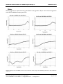
1
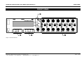
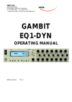
digital audio
weiss engineering ltd.
Florastrasse 42, 8610 Uster, Switzerland
+41 1 940 20 06 +41 1 940 22 14
http://www.weiss.ch / http://www.weiss-highend.com
GAMBIT
EQ1-LP
OPERATING MANUAL
Software Version:
0S: 5.0
OPERATING INSTRUCTIONS FOR GAMBIT EQUALIZER EQ1-LP
CONTENTS
CONTENTS
CONTENTS _________________________________________________________________________ 2
FRONT PANEL ______________________________________________________________________ 3
Front Panel Groups ____________________________________________________________________________ 4
INTRODUCTION ____________________________________________________________________ 5
Processing ___________________________________________________________________________________
Display ______________________________________________________________________________________
Snapshots ____________________________________________________________________________________
Remote Control _______________________________________________________________________________
5
5
5
5
OPERATION ________________________________________________________________________ 6
Status Display _________________________________________________________________________________ 6
Band Parameters ______________________________________________________________________________ 7
Controls _____________________________________________________________________________________ 8
M/S Mode___________________________________________________________________________________ 11
Snapshots ___________________________________________________________________________________ 13
Dither______________________________________________________________________________________ 15
Display Resolution ____________________________________________________________________________ 15
LCD Contrast _______________________________________________________________________________ 15
EQ Bypass __________________________________________________________________________________ 15
Remote Control ______________________________________________________________________________ 16
Software Information __________________________________________________________________________ 16
Self Test ____________________________________________________________________________________ 16
TECHNICAL DATA _________________________________________________________________ 17
AES/EBU Input _______________________________________________________________________________
AES/EBU Output _____________________________________________________________________________
Power______________________________________________________________________________________
Overload ___________________________________________________________________________________
Filters ______________________________________________________________________________________
Parameter Table _____________________________________________________________________________
Dither______________________________________________________________________________________
Remote Control Protocol ______________________________________________________________________
Daniel Weiss Engineering Ltd., Florastr. 42, CH-8610 Uster
+41 1 940 20 06 +41 1 940 22 14 http://www.weiss.ch [email protected]
17
17
20
20
20
21
23
24
Page 2 of 28
OPERATING INSTRUCTIONS FOR GAMBIT EQUALIZER EQ1-LP
FRONT PANEL
FRONT PANEL
Graph 1: Front Panel Elements
Daniel Weiss Engineering Ltd., Florastr. 42, CH-8610 Uster
+41 1 940 20 06 +41 1 940 22 14 http://www.weiss.ch
Page 3 of 28
[email protected]
OPERATING INSTRUCTIONS FOR GAMBIT EQUALIZER EQ1-LP
FRONT PANEL
Front Panel Groups
The front panel of the EQ1 offers several control and display features. These can be grouped according to
Graph 1: Front Panel Elements:
- Band Parameters
- Menu
- Controls
- Snapshots
This manual will explain how to operate the EQ1 according to these groups.
The Bypass key is discussed separately in chapter EQ Bypass (p. 15). The “gain/ data” encoder appears
throughout the rest of this manual and is therefore not explained separately.
Daniel Weiss Engineering Ltd., Florastr. 42, CH-8610 Uster
+41 1 940 20 06 +41 1 940 22 14 http://www.weiss.ch
Page 4 of 28
OPERATING INSTRUCTIONS FOR GAMBIT EQUALIZER EQ1-LP
INTRODUCTION
INTRODUCTION
Congratulations on purchasing the Weiss Gambit EQ1-LP linear phase digital equalizer!
The EQ1-LP is a digital equalizer with a linear
phase response. This means that the delay caused
by processing is constant across the whole spectrum, unconstrained by eq settings - this is not
the case with standard equalizers, where signal
delay varies with frequency, depending on the eq
setting.
The sound, or character, of an equalizer has been
said to be influenced by phase response (for example John Watkinson: "...much of the audible
difference between EQs comes down to the phase
response.", Studio Sound 9.97).
The EQ1-LP is therefore the ideal tool for corrective amplitude adjustment, without the unwanted
phase distortion added by standard equalizers.
The EQ1-LP can be switched from linear- to
minimum-phase response, resulting in the exact
same sound as the EQ1-MK2. So for creative
sound designing, there is the benefit of two different sounding equalizers in one machine.
Features of the EQ1-LP include:
Processing
Display
∗ Double logarithmic graph of the magnitude
function of the equalizer calculated in real
time
∗ Status display showing sampling frequency,
channel status data handling, current workspace and snapshot number and a resetable
peak-hold and over-hold per channel
∗ Band display (activated by touch) showing
boost, Q/ slope and frequency settings for
each band
∗ Two over-LED’s with settable number of
consecutive over-samples which cause an
“over” display combined with an over-hold
function
Snapshots
∗ 3 x 128 non-volatile snapshots where all
parameters are stored
∗ A-B workspaces for quick comparison between two settings
Remote Control
∗ Switchable linear-phase or minimum-phase
response. Setting can be stored per snapshot.
∗ Supports MIDI, RS-232 and RS-422 protocols
∗ 24bit digital input, internal 40bit floatingpoint arithmetic, dithered output for 16bit,
20bit or 24bit wordlengths.
∗ Standard MIDI Continuous Controllers for
parameter remote control (including overall gain)
∗ Snapshot automatization with MIDI Program Change Commands
∗ MIDI Dump of Snapshots
Daniel Weiss Engineering Ltd., Florastr. 42, CH-8610 Uster
+41 1 940 20 06 +41 1 940 22 14 http://www.weiss.ch [email protected]
Page 5 of 28
OPERATING INSTRUCTIONS FOR GAMBIT EQUALIZER EQ1-LP
OPERATION
OPERATION
The following explanations assume that the equalizer is in power-up mode, i.e. no menu is active.
If a menu is active, press the “menu” key repeatedly until the status display appears.
Use this value to set the optimal gain for a specific
session. Reset it for every session.
Status Display
Key A
Over-Hold
Key B
Whenever an over is encountered, the boxes to
the side of the peak-hold values are marked.
Key C
Key D
Graph 2: Status Display
The status display consists of four groups displaying audio signal properties and information about
the current state of the EQ1. The groups are
situated adjacent to the softkeys to the right of
the LCD (Graph 2).
Channel Status Group
Situated adjacent to key A, displays the following
information:
∗ sampling frequency in kHz: “44.1”, “ 48”,
“88.2” or “96”
∗ pre-emphasis: “E” appears if pre-emphasis
is set (empty if not used)
The functions of the over-LED’s and the overhold both depend on the NUMBER OF
CONSECUTIVE OVER-SAMPLES setting. To adjust this
setting, press key B once. Use the “gain/ data”
encoder to change the value, then press “menu”
to return to the status display.
This setting defines the number of consecutive
over-samples needed for an over-indication. To
indicate every over-sample, enter 1. If another
value is entered, you are still able to detect a single over-sample with the peak-hold function.
Over-samples are defined as exceeding the
24bit integer range. A full scale signal
(0dBFS) will not be treated as over. A signal
that triggered an over in a previous processor in the audio chain will therefore not
trigger an over in the EQ1 (unless boosted).
∗ input → output channel status data format:
“C” for consumer and “P” for professional
To change the output channel status data format,
press key A and select format type or loop
through.
Peak Group
Situated adjacent to key B, this group contains a
peak-hold and an over-hold for each channel. To
reset these values press key B twice.
Remote Group
Situated adjacent to key C, displays remote control protocol (“MIDI”, “RS 232” or “RS 422”),
channel (“1” - “16”) and status (on/ off, displayed
with check box).
For remote control set-up see chapter Remote
Control.
Peak-Hold
The numeric peak value is measured relative to
0dBFS, where 0dB equals digital full scale.
Daniel Weiss Engineering Ltd., Florastr. 42, CH-8610 Uster
+41 1 940 20 06 +41 1 940 22 14 http://www.weiss.ch [email protected]
Page 6 of 28
OPERATING INSTRUCTIONS FOR GAMBIT EQUALIZER EQ1-LP
OPERATION
Snapshot Display
Bottom line in the status display. Refer to this for
information on current workspace and snapshot.
There are two workspaces (“A” and “B”) for
quick comparison of two equalizer settings. A
workspace can be stored to a snapshot for later
use.
The number of the last recalled snapshot will be
displayed. If you change any value after the recall,
the “=” will change to “≠” to symbolize that the
workspace is not equal to the displayed snapshot
anymore.
For snapshot handling see chapter Snapshots.
Dither Icon
The dither icon is situated right next to key D
(see Graph 2). If dither is off, the icon contains
the number “24“, the word length of the output
signal in bits. Turning dither on will produce arrows above and below the new word length
number (“16“ or “20“). Additionally, if autoblacking is enabled, the bottom right corner of
the icon is inverted.
For details on dither refer to chapter Dither.
Daniel Weiss Engineering Ltd., Florastr. 42, CH-8610 Uster
+41 1 940 20 06 +41 1 940 22 14 http://www.weiss.ch [email protected]
Page 7 of 28
OPERATING INSTRUCTIONS FOR GAMBIT EQUALIZER EQ1-LP
Band Parameters
What Is A Band?
The EQ1 has seven independent bands per channel. A band has the following parameters which
can be adjusted separately for each band:
OPERATION
To activate a band and see its detailed parameter
values, touch any knob in a band (see Graph 1, ). The active band’s parameter values will be
shown in the band display (see Graph 4) replacing
the status display, and its LED chain will light up,
showing you where to adjust the parameter values.
1. Mode
2. Boost
3. Q/ Slope / Shape
4. Frequency
Mode specifies the filter type. There are five filter
types (low and high cut, low and high shelving and
peaking) and a bypass mode. Each band has its
own five-LED chain to indicate its active mode
(see Graph 3).
Graph 3: Mode LEDs
High Shelving
Low Shelving
Peaking
Graph 4: Band Display
Depending on the setting of “Auto Switchback From Band To Status Display”, this
display will hold or disappear again after
having released the knob.
To change the “Auto Switchback From Band To
Status Display” setting, press the “menu” key,
then select “Controls” with key B. The value can
now be changed with key B.
Range
The parameters’ range is independent of the
mode and is listed at page 21.
High Cut
Low Cut
Daniel Weiss Engineering Ltd., Florastr. 42, CH-8610 Uster
+41 1 940 20 06 +41 1 940 22 14 http://www.weiss.ch [email protected]
Page 8 of 28
OPERATING INSTRUCTIONS FOR GAMBIT EQUALIZER EQ1-LP
Adjusting Band Parameters
Controls
To adjust boost, Q/ slope or frequency simply
turn the corresponding knob (see Table 1).
Peaking-Filter
Shelve-Filter
Cut-Filter
OPERATION
See Graph 1: Front Panel Elements, .
“boost”
“Q/ slope”
“frequency”
set boost
set boost
-
set Q
set shape
set slope
set centre frequency
set 3dB frequency
set -3dB frequency
Table 1
To adjust the mode, activate the band. Press a
key (Table 2) to change the mode value. The
active mode is highlighted and the adjacent softkey is lit.
Mode
CH1 & CH2
These two keys patch the band controls to the
according channels. The band controls can either
be separate for each channel or ganged together.
Key A
Key B
Key C
Key D
toggle lo- / hi-shelve
Peaking
toggle lo- / hi-cut
bypass
Table 2
If the band bypass is on (highlighted), its filter
settings (type and parameters) are saved but have
no effect on the audio signal. Turning bypass off
will restore the previous band settings.
Bypassing all bands is sonically equivalent to
using the overall bypass (refer to EQ Bypass)
if the gain is set to 0.0dB.
The key is lit for the active channel.
To copy CH1 settings to CH2 or vice versa, press
the “copy” key and select an option (Graph 6).
Ganged
When this key is lit, the band controls act for both
channels simultaneously. Switching channels while
the “ganged” key is lit will activate CH1 and CH2
settings alternately for both channels.
If ganged is off, the controls will affect the active
channel only.
Daniel Weiss Engineering Ltd., Florastr. 42, CH-8610 Uster
+41 1 940 20 06 +41 1 940 22 14 http://www.weiss.ch [email protected]
Page 9 of 28
OPERATING INSTRUCTIONS FOR GAMBIT EQUALIZER EQ1-LP
Linear Phase
The linear-phase feature is enabled by pressing
this key. If it is lit, the EQ1-LP is in linear-phase
mode, otherwise it is in minimum-phase mode.
This mode information is kept in the current
workspace, and can also be stored alongside all
the other workspace parameters in a snapshot.
Each snapshot is thus either linear-phase or a
minium-phase (this also counts for A-B workspaces: they can each have their own setting of
the mode switch).
Caution: Due to the nature of the DSP algorithm, the linear-phase mode is not suitable
for notch filtering. Use the EQ1 in minimumphase mode for this application.
The following text describes basic signal processing
architectures for digital filter implementation, and
how exactly the EQ1-LP achieves the linear-phase
response. It can be skipped be the technically
uninterested person.
There are two basic kinds of frequency dependent amplifiers (commonly known as filters): IIR
(infinite impulse response) and FIR (finite impulse
response). Both kinds can be implemented either
in digital or analogue domain, as discussed below.
IIR filters
Digital IIR filters can be derived from their analogue IIR counterpart, thus transforming the analogue filter parameters (Q, frequency, gain, etc.)
into the digital domain. This is the procedure for
digital EQ design favoured by Weiss Engineering
and most manufacturers, because it maintains the
well understood parameters from the analogue
equalizers. IIR filters have certain properties:
1. An infinite impulse response, hence the name
(in practice, the impulse response will eventually decay below the noise floor).
2. Some kind of phase response. Practical criteria dictate a so called minimum-phase response (which is linked to the amplitude re-
OPERATION
sponse), though this not necessarily need to
be so, in fact, virtually any arbitrary phase response is possible.
Linear-phase IIR filters
Contrary to common belief, non-minimum phase
IIR systems are realizable, this usually involves a
minimum-phase section followed by an all-pass
section with any arbitrary phase response. Thus,
a linear-phase system would have a minimumphase system followed by an all-pass system designed to have a phase response which, when
added to the minimum-phase, will result in a linear phase response. This can (theoretically) be
done in the analogue as well as the digital domain.
However, there are certain practical problems
which make this method difficult, if not impossible.
FIR filters
There is no direct way to transform analogue
equalizer parameters to digital FIR systems,
though there are algorithms that try to emulate a
specific frequency response on a FIR system.
These yield quite exact copies of the amplitude(and, if required, even of the phase-) response.
FIR filters also have certain properties:
1. A finite impulse response, resulting in a fixed
length output when excited by an input pulse.
2. Any arbitrary phase response.
3. A delay.
So linear phase-response is not a problem to
achieve with FIR filters. But IIR filters are favoured
over FIR filters in audio equalizers because of
several reasons:
4. The long delay of the FIR equalizer systems is
usually not acceptable for (online) audio processing.
5. The parameters of analogue equalizers are
easier maintained in IIR than FIR filters.
6. There is a considerably larger expense involved for tuneable FIR audio equalizer than
for the IIR equivalent.
7. Digital signal processing for audio band FIR
filters is computationally more intensive than
for IIR filters.
Daniel Weiss Engineering Ltd., Florastr. 42, CH-8610 Uster
+41 1 940 20 06 +41 1 940 22 14 http://www.weiss.ch [email protected]
Page 10 of 28
OPERATING INSTRUCTIONS FOR GAMBIT EQUALIZER EQ1-LP
OPERATION
FIR filters are used mainly for applications requiring extremely narrow transition bandwidths combined with no audible distortion (i.e. phase shifts)
in the pass band (although a so called pre-echo
can become a problem in FIR implementations).
Examples (in audio applications) are interpolation
filters for sample rate conversion and band-split
filters for crossovers.
In order to avoid the technical and commercial
drawbacks of FIR systems for audio equalizers,
the Weiss Gambit EQ1-LP uses yet another
scheme for linear phase-response based on the
following property of IIR filters: if one processes a
piece of digital audio with any IIR system, then
time-reverses this piece and processes it again
with the same IIR system, one will effectively have
cancelled out the phase response of the IIR system, while squaring the amplitude response (as
can be verified on any DAW). The solution lies in
the time-reversal (non-causality) of this algorithm.
So effectively, the EQ1-LP is a time machine,
sending the audio signal backwards through
time...
On a side note, this algorithm was already experimentally implemented by Weiss Engineering
in 1995, but only now is current DSP hardware
powerful enough to realize the seven band 96kHz
requirements of the EQ1-LP.
Daniel Weiss Engineering Ltd., Florastr. 42, CH-8610 Uster
+41 1 940 20 06 +41 1 940 22 14 http://www.weiss.ch [email protected]
Page 11 of 28
OPERATING INSTRUCTIONS FOR GAMBIT EQUALIZER EQ1-LP
M/S Mode
A 2-channel stereo signal can be transformed
from the L/R (left/right) domain into the M/S
(mid/side) domain and back without any signal
degradation.
In the M/S domain, the two channels representing
the stereo signal contain information on the Mid
(mono) and Side content of the stereo signal.
Equalizing in the M/S domain can, for example,
just affect vocals or instruments centred in the
stereo mix. Or, by boosting the S channel, result
in frequency dependent stereo-base enhancement.
OPERATION
If one decides to decode a M/S recording, for
example, the input would have to be set to M/S
and the output to L/R – the eq section can be set
to either, depending upon which domain one
wants to eq.
Another option is encoding a L/R signal to M/S for
further M/S processing outside the EQ1-MK2.
Then the output will have to be set to M/S and
the input to L/R. Again, the eq section can operate in either domain.
To compensate for different non-standardized
M/S formats, there is a L/R swap option. This, as
the name implies, will swap the decoded left and
right channels, and will be used when decoding
M/S recorded material to L/R.
On/Off
Press the “menu” key, then select the “System > MS coding” option. This opens the “MS Coding
Setup” menu (see Graphic 5).
Graphic 5: MS Coding Setup Menu
The MS mode is activated by toggling the “M/S
on/off” value with key C. The M/S icon will appear in the top left corner of the frequency response window to indicate that M/S mode is active.
Setup
Several possible M/S configurations can be accomodated for in the EQ1. This can be achieved
with the “M/S Setup” option by pressing key D.
The user is then taken through a procedure to
specify the setup to be used. The “back” and
“next” keys help negotiating within the setup
procedure.
To eq a standard L/R stereo signal in the M/S domain, the input and output sections are specified
as L/R, while the EQ is set to M/S.
Daniel Weiss Engineering Ltd., Florastr. 42, CH-8610 Uster
+41 1 940 20 06 +41 1 940 22 14 http://www.weiss.ch [email protected]
Page 12 of 28
OPERATING INSTRUCTIONS FOR GAMBIT EQUALIZER EQ1-LP
Snapshots
See Graph 1: Front Panel Elements, .
Snapshots are copies of the EQ1 parameter settings. This allows recalling complete set-ups including all filter parameters and controls settings.
Snapshots can be recalled from the front panel or
by remote control (e.g. MIDI Program Change).
A-B Comparison
You can compare two settings by using the two
workspaces “A” and “B”. To toggle between the
two press the “A-B” key. Restore a snapshot or
simply adjust the filters in one workspace, then
switch to the other to compare.
To copy workspace “A” to “B” or vice versa,
press the “copy” key and select an option (Graph
6).
OPERATION
If the “Preview” option is not marked, the
snapshots will be recalled as soon as you
enter a new number.
Press the “recall” key to return to the status display.
“Recall # 0”
Snapshot 0 is used as a resetting curve. To reset
the current workspace, press the “recall” key
then the“ Recall # 0” key.
Store
To store the current workspace to a snapshot,
press the “store” key. With the “gain/ data” encoder enter the snapshot number where you
want to store the workspace, then press key D.
Snapshots can be prevented from accidental erasure by marking the “Safe” option.
A setting can be stored to multiple snapshots.
Press “To Range” in the “store” menu.
Graph 6: "copy" menu
The active workspace is shown in the status display.
Graph 7: Store To Range Menu
Recall
To recall a snapshot press the “recall” key. Notice that the snapshot will be copied into the active workspace. If you do not want to lose
these settings, switch to the other workspace by
pressing the “A-B” key.
Using the “gain/ data” encoder enter the number
of the snapshot you want to recall. The graph of
the snapshot will be displayed in preview mode
(outlined) to facilitate finding a certain setting.
However, the audio signal is not affected if the
“Preview” option is marked. Once you have
found the snapshot, press key D to restore it.
Press the adjacent keys to select “Start” and
“End” snapshot number, use the “gain/ data”
encoder to enter a value (Graph 7). Pressing
“Execute” will store the setting from the displayed workspace (“A” or “B”) to all snapshots
between the Start and End value. A “Safe” snapshot will not be overwritten.
Backup
All 128 snapshots can be transferred to another
non-volatile memory area for later reference.
There is enough memory for two complete snapshot sets to be backed up.
Press the “menu” key then choose the “System”
and then the “Backup” option to arrive at the
backup display (Graph 8).
Daniel Weiss Engineering Ltd., Florastr. 42, CH-8610 Uster
+41 1 940 20 06 +41 1 940 22 14 http://www.weiss.ch [email protected]
Page 13 of 28
OPERATING INSTRUCTIONS FOR GAMBIT EQUALIZER EQ1-LP
OPERATION
Loading
Graph 8: Backup Display
Select “Create #1” to save the current snapshots
to bank 1. Select “Restore #1” to overwrite the
current snapshots with bank 1 (ditto for bank 2).
To load a snapshot dump from sequencer, simply
play the dump sequence. The EQ1 will automatically switch into receive mode and display statistics about the snapshots it’s receiving. If the
transmission was OK and no errors occured, the
program switches back to normal mode. Upon
error, you have to manually switch back to normal mode.
When playing back the dump sequence, always use the same speed as when the sequence was recorded.
A backup will overwrite “safe” snapshots.
Reset
To reinstall the factory snapshots you must press
the “menu” key then choose the “System” and
then the “Reset all” option. This will reset the
current snapshots. The snapshots that have been
backed up are preserved.
Dumping
The settings of all 128 snapshots can be dumped
to a remote control port to be stored externally.
Please make sure that you have connected everything correctly and that the proper remote control port is activated (see chapter Remote Control for setup).
When dumping to a MIDI-sequencer, make sure
that the sequencer is not sending or receiving
data other than the snapshot dump.
Certain sequencers are not capable of handling the amount of data output by the EQ1
and might crash during or after the dump
process.
Always save the sequencer settings before
recording a dump!
To initiate a dump, press the “menu” key then
choose the “System” and then the “Dump” option. Start the recording process on the sequencer, then press “Transmit”. This releases the
dump to the sequencer.
Daniel Weiss Engineering Ltd., Florastr. 42, CH-8610 Uster
+41 1 940 20 06 +41 1 940 22 14 http://www.weiss.ch [email protected]
Page 14 of 28
OPERATING INSTRUCTIONS FOR GAMBIT EQUALIZER EQ1-LP
Dither
The DS1-MK2 v2.0 is able to apply POW-R type
dither algorithms to avoid distortion when requantizing from 24bit to 16bit or 20bit output
word length (see TECHNICAL DATA for dither
specifications).
To toggle dither on/off, press key D twice. To see
dither status refer to the status display (see
Fehler! Verweisquelle konnte nicht gefunden werden. p. Fehler! Textmarke
nicht definiert.).
Word Length
To set output word length, press key D and select the appropriate wordlength.
Setup
Press key D then chose the setup menu. This
leads to the menu where the type of POW-R
dither can be chosen (see TECHNICAL DATA
for dither specifications). Also selectable is:
Auto-Blacking
OPERATION
range that suits your curve and press the “menu”
key again to return to the status display.
LCD Contrast
To change the display contrast, press the “menu”
key, then select “Display”. Adjust contrast with
the “gain/ data” encoder.
EQ Bypass
The EQ1 can be completely bypassed with the
green “bypass” key below the mains switch. If the
“bypass” key is lit, the EQ1 is absolutely transparent, making the output signal bit equal to the input signal.
While bypass is active (key is lit), the EQ1 works
in preview mode. This allows you to change parameters without actually affecting the audio signal. The frequency curve is drawn outlined over
the flat bypass curve, so you still get the advantage of the graph when modifying parameters.
As soon as bypass is deactivated, the outlined
curve takes effect.
If auto-blacking is activated by marking the “0 IN
0 OUT“ option, dither will be turned off if the
input signal is zero As soon as the input signal
changes, dither will be turned on again. This ensures that pauses between programmes are still
digital zero, even if dither is activated.
Display Resolution
The magnitude of the overall frequency response
of the EQ1 is drawn on the LC display. This immensely facilitates filter parameter adjustment
because it takes one look to see what the equalizer is doing instead of having to work it out from
the parameter values.
To obtain the maximum benefit from the graph,
set the vertical display resolution to a range that
just covers your settings. There are four ranges
available:
± 6dB, ± 12dB, ± 18dB, ± 24dB
To change the display resolution, press the
“menu” key, then select “Display”. Choose a
Daniel Weiss Engineering Ltd., Florastr. 42, CH-8610 Uster
+41 1 940 20 06 +41 1 940 22 14 http://www.weiss.ch [email protected]
Page 15 of 28
OPERATING INSTRUCTIONS FOR GAMBIT EQUALIZER EQ1-LP
Remote Control
All band parameters as well as control settings
can be set externally.
To see remote control status refer to the status
display.
OPERATION
Software Information
Press the “menu” key, then select the “System > About” option. This displays a screen with all
the relevant information on your EQ1 and how to
reach us. Have this page ready when you want to
report a problem.
Protocol
To select a remote control protocol, press key C
from the status display menu. Select either “RS
232”, “RS 422” or “MIDI”. This will determine
which port at the rear of the EQ1 is active. The
other inactive ports will be ignored.
Self Test
Press the “menu” key, then select the “System > Selftest” option. This will start a procedure
that checks the functionality of all input and display devices.
Press the “menu” key to return to the status display if you do not want to change remote on/ off
status.
When selecting a port other than MIDI you have
to specify the baud rate. Refer to the remote
control software manual for correct settings. The
set baud rate is displayed to ensure proper setup.
Channel
To change the remote control channel number,
press key C (adjacent to the remote control
field). Use the “gain/ data” encoder to select a
value between 1 and 16. Press the “menu” key to
return to the status display.
The EQ1 does not support poly-mode (listening
on all channels). Select the same channel on the
controller software as is set internally, else no
remote control messages will be received.
On/ Off
To enable or disable remote control, press key C
(adjacent to the remote control field). Press it
again to toggle the “ON/ OFF”-value.
While remote control is off, data will still be sent
to the selected port. Also, the MIDI THRU output will always mirror the MIDI IN input data
regardless of “ON/ OFF” or protocol status.
Daniel Weiss Engineering Ltd., Florastr. 42, CH-8610 Uster
+41 1 940 20 06 +41 1 940 22 14 http://www.weiss.ch [email protected]
Page 16 of 28
OPERATING INSTRUCTIONS FOR GAMBIT EQUALIZER EQ1-LP
TECHNICAL DATA
TECHNICAL DATA
AES/EBU Input
Sampling Frequencies:
Maximum Input Wordlength:
Channel Status Data:
Channel Status Bits
forwarded to AES/EBU output:
Connector:
44.1 kHz, 48.0 kHz, 88.2 kHz, 96.0 kHz
24 Bits
Input accepts professional or consumer format.
see table below
XLR female
AES/EBU Output
Sampling Frequencies:
Output Wordlength:
Connector:
44.1 kHz, 48.0 kHz, 88.2 kHz, 96.0 kHz (always the same as the input)
24 Bits
XLR male
AES/EBU Channel Status Data
The EQ1 allows to convert the incoming Channel Status Data as follows:
∗ From Consumer to Professional
∗ From Professional to Consumer
∗ Transparent mode, i.e. Channel Status Data is fed forward to the output without any conversion (one
exception, see below)
Daniel Weiss Engineering Ltd., Florastr. 42, CH-8610 Uster
+41 1 940 20 06 +41 1 940 22 14 http://www.weiss.ch [email protected]
Page 17 of 28
OPERATING INSTRUCTIONS FOR GAMBIT EQUALIZER EQ1-LP
TECHNICAL DATA
The following tables describe how the Channel Status Data bits are generated in the various conversion modes.
Output selected: Consumer format.
Input: Consumer format.
Output:
All bits fed forward (transparent), except for:
Byte 1:
Bits 0..6: 0000000 (category code general)
Bit 7: 1 (original)
Input: Professional format.
Output:
Byte 0:
Bit 0: 0 (consumer)
Bit 1: 0 (audio)
Bit 2: 1 (copy allowed)
Bits 3,4: Preemphasis according to input
Bit 5: 0 (2 channel mode)
Bits 6,7: 00 (Mode 0)
Byte 1:
Bits 0..6: 0000000 (category code general)
Bit 7: 1 (original)
Byte 2:
Bits 0,1,2,3: Sampling Frequency according to input
Bits 4,5: 00 (accuaracy grade II)
Bits 6,7: 00
Bytes 3..23: reserved bytes
Daniel Weiss Engineering Ltd., Florastr. 42, CH-8610 Uster
+41 1 940 20 06 +41 1 940 22 14 http://www.weiss.ch [email protected]
Page 18 of 28
OPERATING INSTRUCTIONS FOR GAMBIT EQUALIZER EQ1-LP
TECHNICAL DATA
Output selected: Professional format.
Input: Professional format.
Output: All bits fed forward (transparent), except for:
Byte 2:
Bits 0,1,2: 001 (max. sample length= 24bit)
Bits 3,4,5: 101 (24 bit word length)
Bits 6,7: 00
Input: Consumer format.
Output:
Byte 0:
Bit 0: 1 (professional)
Bit 1: 0 (audio)
Bits 2,3,4: Preemphasis according to input
Bit 5: 0 (source fs locked)
Bits 6,7: Sampling Frequency according to input
Byte 1:
Bits 0,1,2,3: 0001 (two channel mode)
Bits 4,5,6,7: 0000 (no user bit encoding)
Byte 2:
Bits 0,1,2: 001 (max. sample length= 24bit)
Bits 3,4,5: 101 (24 bit word length)
Bits 6,7: 00
Bytes 3..12: All bits 0
Byte 23:
CRCC byte
Output selected: Transparent.
Input: Any format.
Output:
All bits fed forward (transparent), except if EQ not bypassed:
Byte 2:
Bits 0,1,2: 001 (max. sample length= 24bit)
Bits 3,4,5: 101 (24 bit word length)
Bits 6,7: 00
Daniel Weiss Engineering Ltd., Florastr. 42, CH-8610 Uster
+41 1 940 20 06 +41 1 940 22 14 http://www.weiss.ch [email protected]
Page 19 of 28
OPERATING INSTRUCTIONS FOR GAMBIT EQUALIZER EQ1-LP
TECHNICAL DATA
Power
Mains Voltage:
Fuse rating:
Power Consumption:
110 / 220 Volts with voltage selector
500 mA slow blow
40VA max
Overload
Number of consecutive
over-samples to cause
“over” display:
1..16 settable
Filters
The filter topology used in the EQ1 is a very low noise filter structure for a state of the art performance.
Daniel Weiss Engineering Ltd., Florastr. 42, CH-8610 Uster
+41 1 940 20 06 +41 1 940 22 14 http://www.weiss.ch [email protected]
Page 20 of 28
OPERATING INSTRUCTIONS FOR GAMBIT EQUALIZER EQ1-LP
TECHNICAL DATA
Parameter Table
Frequencies (in Hertz):
13.8, 15.4, 17.3, 19.4, 21.8, 24.5, 27.5, 30.9, 34.6, 38.9, 43.7, 49.0, 50.0, 51.9, 55.0, 58.3, 60.0, 61.7, 65.4,
69.3, 73.4, 77.8, 82.4, 87.3, 92.5, 98.0, 100, 104, 110, 117, 120, 123, 131, 139, 147, 150, 156, 165, 175, 180,
185, 196, 200, 208, 220, 233, 240, 247, 250, 262, 277, 294, 300, 311, 330, 349, 360, 370, 392, 415, 440,
466, 494, 523, 554, 587, 622, 659, 698, 740, 784, 831, 880, 932, 988, 1047, 1109, 1175, 1245, 1319, 1397,
1480, 1568, 1661, 1760, 1865, 1976, 2093, 2217, 2349, 2489, 2637, 2794, 2960, 3136, 3322, 3520, 3729,
3951, 4186, 4435, 4699, 4978, 5274, 5588, 5920, 6272, 6645, 7040, 7459, 7902, 8372, 8870, 9397, 9956,
10548, 11175, 11840, 12544, 13290, 14080, 14917, 15804, 16744, 17740, 18795, 19912, 21096.
Boost/Cuts, applicable to shelving and peaking filters:
All numbers in dB:
-39.0, -36.0, -33.0, -30.0, -27.0, -24.0, -21.0, -18.0, -17.0, -16.0, -15.0, -14.0, -13.0, -12.0, -11.5, -11.0, 10.5, -10.0, -9.5, -9.0, -8.5, -8.0, -7.5, -7.0, -6.5, -6.0, -5.5, -5.0, -4.8, -4.5, -4.3, -4.0, -3.8, -3.5, -3.3, -3.0, 2.9, -2.8, -2.7, -2.6, -2.5, -2.4, -2.3, -2.2, -2.1, -2.0, -1.9, -1.8, -1.7, -1.6, -1.5, -1.4, -1.3, -1.2, -1.1, -1.0, -0.9,
-0.8, -0.7, -0.6, -0.5, -0.4, -0.3, -0.2, -0.1, 0.0, 0.1, 0.2, 0.3, 0.4, 0.5, 0.6, 0.7, 0.8, 0.9. 1.0, 1.1, 1.2, 1.3, 1.4,
1.5,1.6, 1.7, 1.8, 1.9. 2.0, 2.1, 2.2, 2.3, 2.4, 2.5, 2.6, 2.7, 2.8, 2.9, 3.0, 3.3, 3.5, 3.8, 4.0, 4.3, 4.5, 4.8, 5.0, 5.5,
6.0, 6.5, 7.0, 7.5, 8.0, 8.5, 9.0, 9.5, 10.0, 10.5, 11.0, 11.5, 12.0, 12.5, 13.0, 13.5, 14.0, 14.5, 15.0, 15.5, 16.0,
17.0, 18.0.
Q, applicable to peaking filters:
0.20, 0.25, 0.30, 0.35, 0.40, 0.45, 0.50, 0.55, 0.60, 0.65, 0.70, 0.75, 0.80, 0.85, 0.90, 0.95, 1.00, 1.05, 1.10,
1.15, 1.20, 1.25, 1.30, 1.35, 1.40, 1.45, 1.50, 1.55, 1.60, 1.65, 1.70, 1.75, 1.80, 1.85, 1.90, 1.95, 2.00, 2.10,
2.20, 2.30, 2.40, 2.50, 2.60, 2.70, 2.80, 2.90, 3.00, 3.10, 3.20, 3.30, 3.40, 3.50, 3.60, 3.70, 3.80, 3.90, 4.00,
4.10, 4.20, 4.30, 4.40, 4.50, 4.60, 4.70, 4.80, 4.90, 5.00, 5.50, 6.00, 6.50, 7.00, 7.50, 8.00, 8.50, 9.00, 9.50,
10.0, 11.0, 12.0, 13.0, 14.0, 15.0, 16.0, 17.0, 18.0, 19.0, 20.0, 22.0, 24.0, 26.0, 28.0, 30.0, 35.0, 40.0, 45.0,
50.0, 55.0, 60.0, 65.0, 70.0, 75.0, 80.0, 85.0, 90.0, 95.0, 100, 110, 120, 130, 140, 150, 160, 170, 180, 190,
200, 220, 240, 260, 280, 300, 350, 400, 450, 500, 550, 600, 650
Shape, applicable to shelving filters:
1, 2, 3, 4, 5, 6, 7, 8, 9, 10, 11, 12, 13, 14, 15, 16, 17, 18, 19, 20, 21, 22, 23, 24, 25, 26, 27, 28, 29, 30, 31, 32,
33, 34, 35, 36, 37, 38, 39, 40 ,41, 42, 43, 44, 45, 46, 47, 48, 49, 50, 51, 52, 53, 54, 55, 56, 57, 58, 59, 60, 61,
62, 63, 64, 65, 66, 67, 68, 69, 70, 71, 72, 73, 74, 75, 76, 77, 78, 79, 80, 81, 82, 83, 84, 85, 86, 87, 88, 89, 90,
91, 92, 93, 94, 95, 96, 97, 98, 99, 100, 101, 102, 103, 104, 105, 106, 107, 108, 109, 110, 111, 112, 113, 114,
115, 116, 117, 118, 119, 120, 121, 122, 123, 124, 125, 126, 127, 128
Slope, applicable to cut filters:
0dB/octave, 6dB/ octave, 12dB/ octave in minimum-phase mode
0dB/octave, 12dB/ octave, 24dB/ octave in linear-phase mode
Daniel Weiss Engineering Ltd., Florastr. 42, CH-8610 Uster
+41 1 940 20 06 +41 1 940 22 14 http://www.weiss.ch [email protected]
Page 21 of 28
OPERATING INSTRUCTIONS FOR GAMBIT EQUALIZER EQ1-LP
TECHNICAL DATA
Overall Gain:
All numbers in dB:
-∞, -92.0, -89.0, -86.0, -83.0, -80.0, -77.0, -74.0, -71.0, -68.0, -65.0, -62.0, -59.0, -56.0, -53.0, -50.0, -48.0, 46.0, -44.0, -42.0, -40.0, -39.0, -38.0, -37.0, -36.0, -35.0, -34.0, -33.0, -32.0, -30.0, -29.5, -29.0, -28.5, -28.0,
-27.5, -27.0, -26.5, -26.0, -25.5, -25.0, -24.5, -24.0, -23.5, -23.0, -22.5, -22.0, -21.5, -21.0, -20.5, -20.0, 19.5, -19.0, -18.5, -18.0, -17.5, -17.0, -16.5, -16.0, -15.5, -15.0, -14.5, -14.0, -13.5, -13.0, -12.5, -12.0, -11.5,
-11.0, -10.5, -10.0, -9.5, -9.0, -8.5, -8.0, -7.5, -7.0, -6.5, -6.0, -5.8, -5.6, -5.4, -5.2, -5.0, -4.8, -4.6, -4.4, -4.2, 4.0, -3.8, -3.6, -3.4, -3.2, -3.0, -2.8, -2.6, -2.4, -2.2, -2.0, -1.8, -1.6, -1.4, -1.2, -1.0, -0.8, -0.6, -0.4, -0.2, 0.0,
0.5, 1.0, 1.5, 2.0, 2.5, 3.0, 3.5, 4.0, 4.5, 5.0, 5.5, 6.0, 6.5, 7.0, 7.5, 8.0, 8.5, 9.0, 9.5, 10.0
Daniel Weiss Engineering Ltd., Florastr. 42, CH-8610 Uster
+41 1 940 20 06 +41 1 940 22 14 http://www.weiss.ch [email protected]
Page 22 of 28
OPERATING INSTRUCTIONS FOR GAMBIT EQUALIZER EQ1-LP
TECHNICAL DATA
Dither
Dithering algorithm is implemented using the POW-R set of algorithms. Graph shows the three algorithms
at 44.1kHz and 88.2kHz sampling rates each.
Graph 9: Output spectrum with 80dBFS / 1kHz sine wave, dithered to 16 Bits, using the three POW-R algorithms at 44.1kHz and 88.2kHz
respectively
Daniel Weiss Engineering Ltd., Florastr. 42, CH-8610 Uster
+41 1 940 20 06 +41 1 940 22 14 http://www.weiss.ch [email protected]
Page 23 of 28
OPERATING INSTRUCTIONS FOR GAMBIT EQUALIZER EQ1-LP
TECHNICAL DATA
Remote Control Protocol
MIDI Implementation
Parameter Remote Control
All band parameters plus the controls parameters are remote controllable. Each parameter has its corresponding MIDI controller number.
According to the different parameters, the controllers are limited in their range. Invalid values are replaced
by the maximum allowable values.
Following is a list of the supported MIDI system inclusive commands:
Action
MIDI Message
Status Byte
Data Byte(s)
Comment
Restore Snapshot
Program Change
1100 cccc
0ppp pppp
(cccc) Channel No.
0 - 127
Adjust Boost/Cut
CH1 Band 1
Control Change
1011 cccc
00000000 ($00)
0vvv vvvv
Adjust Q
CH1 Band 1
Control Change
1011 cccc
00000001 ($01)
0vvv vvvv
(cccc) Channel No.
(vvvvvvv) New Value:
0 - 127
Adjust Frequency
CH1 Band 1
Control Change
1011 cccc
00000010 ($02)
0vvv vvvv
(cccc) Channel No.
(vvvvvvv) New Value:
0 - 127
Adjust Slope
CH1 Band 1
Control Change
1011 cccc
00000011 ($03)
0vvv vvvv
(cccc) Channel No.
(vvvvvvv) New Value:
0-2
Adjust Band Mode
CH1 Band 1
Control Change
1011 cccc
00000100 ($04)
0vvv vvvv
(cccc) Channel No.
(vvvvvvv) New Value:
0-9
CH1 Band 2
CH1 Band 3
CH1 Band 4
CH1 Band 5
CH1 Band 6
CH1 Band 7
CH2 Band 1
CH2 Band 2
CH2 Band 3
CH2 Band 4
CH2 Band 5
CH2 Band 6
CH2 Band 7
Control Change
Control Change
Control Change
Control Change
Control Change
Control Change
Control Change
Control Change
Control Change
Control Change
Control Change
Control Change
Control Change
...
...
...
...
...
...
...
...
...
...
...
...
...
$05 - $09
$0A - $0E
$0F - $13
$14 - $18
$19 - $1D
$1E - $22
$23 - $27
$28 - $2C
$2D - $31
$32 - $36
$37 - $3B
$3C - $40
$41 - $45
Overall Gain CH1
Control Change
1011 cccc
01000110 ($46)
0vvv vvvv
(cccc) Channel No.
(vvvvvvv) New Value:
0 - 127
Overall Gain CH2
Control Change
1011 cccc
01000111 ($47)
0vvv vvvv
(cccc) Channel No.
(vvvvvvv) New Value:
Daniel Weiss Engineering Ltd., Florastr. 42, CH-8610 Uster
+41 1 940 20 06 +41 1 940 22 14 http://www.weiss.ch [email protected]
(ppppppp) New Prog No:
(cccc) Channel No.
(vvvvvvv) New Value:
0 - 127
Page 24 of 28
OPERATING INSTRUCTIONS FOR GAMBIT EQUALIZER EQ1-LP
TECHNICAL DATA
0 - 127
CH1 / 2 SELECT
Control Change
1011 cccc
01001000 ($48)
0vvv vvvv
(cccc) Channel No.
(vvvvvvv) New Value:
0, 1
EQ Bypass
Control Change
1011 cccc
01001001 ($49)
0vvv vvvv
(cccc) Channel No.
(vvvvvvv) New Value:
0, 1
Set Ganged Mode
Control Change
1011 cccc
01001010 ($4A)
0vvv vvvv
(cccc) Channel No.
(vvvvvvv) New Value:
0, 1
Toggle A <> B
Control Change
1011 cccc
01001011 ($4B)
0vvv vvvv
(cccc) Channel No.
(vvvvvvv) New Value:
0, 1
MSC Mode
Control Change
1011 cccc
01001100 ($4C)
0vvv vvvv
(cccc) Channel No.
(vvvvvvv) New Value:
Bit 0: on/off, 1=on
Bit 1: Input: 1=MSC, 0=L/R
Bit 2: EQ:
1=MSC, 0=L/R
Bit 3: Output: 1=MSC, 0=L/R
Bit 4: 1 = CH swap, 0= norm
1111 1111
-
Recall Snapshot 0 to WS A
System Reset
Daniel Weiss Engineering Ltd., Florastr. 42, CH-8610 Uster
+41 1 940 20 06 +41 1 940 22 14 http://www.weiss.ch [email protected]
Page 25 of 28
OPERATING INSTRUCTIONS FOR GAMBIT EQUALIZER EQ1-LP
TECHNICAL DATA
Dump Remote Control
All System-Exklusive commands consist of a header, a message type, possible data and the EOS (end of system exclusive). Below is the format of the header:
Byte
Value
Description
Section
1
F0
Sysex
Header
2
00
Manufacturer's ID
3
30
Manufacturer's ID
4
5A
Manufacturer's ID
5
06
Model ID: 6 = Gambit EQ
6
0000nnnn
Device ID: -> Midi channel number
Following is a list of the supported MIDI system exclusive commands (without header):
Snapshot format for dump. A complete dump consists of 128 snapshots:
Byte
Value
Description
Section
1-6
...
...
Header
7
00000001
message = Snapshot dump
Message Type
8
0nnnnnnn
Package number
Data
9
0nnnnnnn
scale set number
10 - 265
0nnnnnnn
256 Bytes of Snapshot data
266
0ccccccc
Checksum without byte one (F0 Sysex Command)
Checksum
267
F7
EOS
EOS
Byte
Value
Description
Section
1-6
...
...
Header
7
00000010
message = dump request
Message Type
8
F7
EOS
EOS
Byte
Value
Description
Section
1-6
...
...
Header
7
00000011
message = version request
Message Type
8
F7
EOS
EOS
Byte
Value
Description
Section
1-6
...
...
Header
7
00000100
message = send version
Message Type 4
( 0..7F)
Dump request:
Version request:
Version send:
Daniel Weiss Engineering Ltd., Florastr. 42, CH-8610 Uster
+41 1 940 20 06 +41 1 940 22 14 http://www.weiss.ch [email protected]
Page 26 of 28
OPERATING INSTRUCTIONS FOR GAMBIT EQUALIZER EQ1-LP
TECHNICAL DATA
8
0vvvvvvv
OS Version
data
9
0vvvvvvv
DSP Version
10
0vvvvvvv
Scale Version
11
0vvvvvvv
Coeff. Version
12
F7
EOS
EOS
Workspace and Settings request:
Byte
Value
Description
Section
1-6
...
...
Header
7
00000110
message = send all parameters as single controler messages Message Type
8
F7
EOS
EOS
Programming Mode:
Note: This command triggers the programming mode in th e EQ1. In this mode operation from
the front panel is impossible!
Byte
Value
Description
Section
1-6
...
...
Header
7
00000101
message = enter programming mode
Message Type
8
F7
EOS
EOS
Daniel Weiss Engineering Ltd., Florastr. 42, CH-8610 Uster
+41 1 940 20 06 +41 1 940 22 14 http://www.weiss.ch [email protected]
Page 27 of 28
OPERATING INSTRUCTIONS FOR GAMBIT EQUALIZER EQ1-LP
TECHNICAL DATA
RS-232
The implementation is equal to MIDI.
Connector Type:
D-SUB female, 9 pin, Pinout:
pin 1: n.c.
pin 2: RS232 output
pin 3: RS232 input
pin 4: connected to pins 6, 8
pin 5: ground
pin 6: connected to pins 4, 8
pin 7: n.c.
pin 8: connected to pins 4, 6
pin 9: n.c.
RS-422
The implementation is equal to MIDI.
Connector Type:
D-SUB female, 9 pin, Pinout:
pin 1: remote input +
pin 2: remote output +
pin 3: n.c.
pin 4: ground
pin 5: ground
pin 6: remote input pin 7: remote output pin 8: ground
pin 9: ground
Daniel Weiss Engineering Ltd., Florastr. 42, CH-8610 Uster
+41 1 940 20 06 +41 1 940 22 14 http://www.weiss.ch [email protected]
Page 28 of 28